


Languages
Pages
Legal


Y. Unno, 2009/2/24 1
Status of Piezo-Transformer DC-DC Converters
Y. Unno (KEK)
M. Imori, Y. Kanada (U. Tokyo)
S. Imada (NF KK)
M. Katsuno (NEC-Tokin KK)

Y. Unno, 2009/2/24 2
Power Supplies with PET• Piezo-Electric Transformer (PET)
InputOutput
PE ceramicsInner elecrode
€
1
2CinVin
2 =1
2CoutVout
2
γ =VoutVin
=CinCout
(Perfect) Transformer ratio is
Advantages of PET:Non-magneticRadiation tolerantIsolation of primary and secondary

Y. Unno, 2009/2/24 3
Development of HV Power Supply
• Status– HV (Step-up PE
T)• 1 kV - 5-10 mA• Evaluating with e
xisting Step-up PET and power supply board

Y. Unno, 2009/2/24 4
Step-up HV PET Evaluation
• Demonstrated! – 1 kV - 5 mA – with existing PET
• Issues– Loss– Ripple
• New optimized PET to come
Source 15 V Load 200 kÉ∂
Output[V]
Freq[kHz]
Output{A]
Ripple[Vp-p] Eff [%]
0 79 0.00 0
500 70.6 2.50 5.4 12%
602 69.5 3.01 6.6 17%
704 68.3 3.52 8 27%
802 67.5 4.01 9.6 34%
903.4 67 4.52 11 39%
1000 66.5 5.00 12 47%
1102 65.8 5.51 14 50%
1202 65.4 6.01 16 53%

Y. Unno, 2009/2/24 5
Development of LV Power Supply
• LV (Step-down PET)– Goal: 2V - 4 A– New fabrication of co
mpact Step-down PET
• 14 mm x 14 mm x 4 mm
– Power supply test board has been fabricated
Y. Unno, 2009/2/24 6
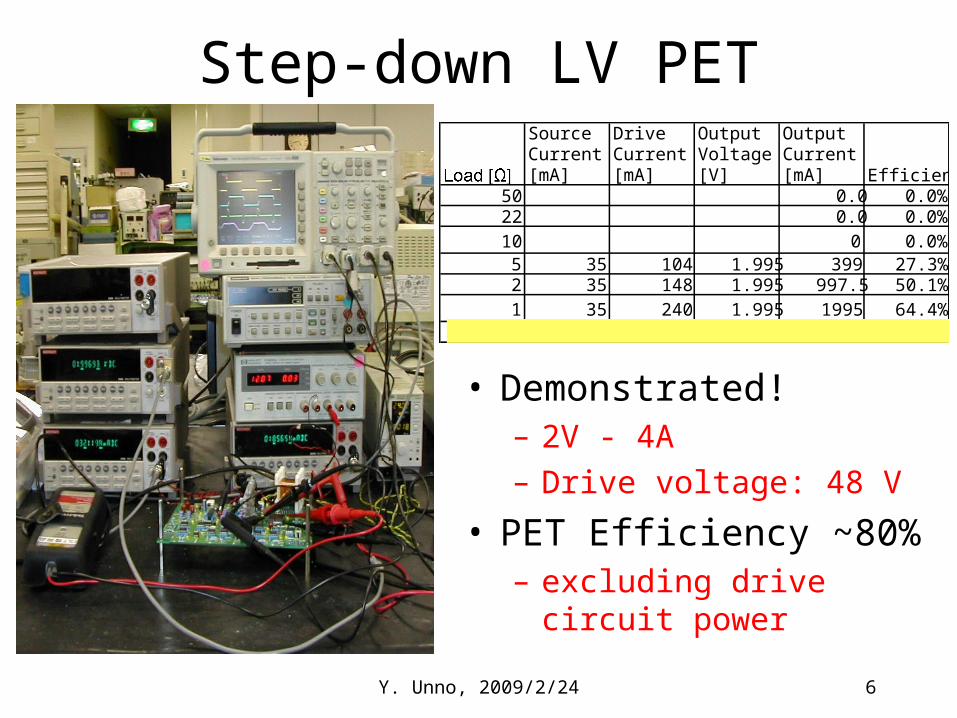
Step-down LV PET
• Demonstrated!– 2V - 4A– Drive voltage: 48 V
• PET Efficiency ~80%– excluding drive circuit
power
SourceCurrent[mA]
DriveCurrent[mA]
OutputVoltage[V]
OutputCurrent[mA] Efficiency
50 0.0 0.0%22 0.0 0.0%10 0 0.0%
5 35 104 1.995 399 27.3%2 35 148 1.995 997.5 50.1%1 35 240 1.995 1995 64.4%
0.5 35 480 1.994 3988 66.6%

Y. Unno, 2009/2/24 7
Summary• Step-up HV PET power supply
– 1 kV - 5 mA achieved– Issues identified
• A compact Step-down LV PET is fabricated– 2 V - 4 A achieved– PET efficiency ~80%

Y. Unno, 2009/2/24 8
Backup

Y. Unno, 2009/2/24 9
High Voltage Power Supply Incorporating Piezoelectric
Transformer
Masatosi Imori, Yoshinobu Unno1, Yasumasa Kanada2, Satoru Imada3 and Masafumi Katsuno4
ICEPP, University of Tokyo, 7-3-1 Hongo, Bunkyo-ku Tokyo 113-0033,Japan1KEK, 1-1 Oho, Tsukuba, Ibaraki 305-0801 Japan2Information Technology Center, University of Tokyo, 2-11-16 Yayoi, Bunkyo-ku Tokyo 113-8658, Japan3NF Corporation, 6-3-20 Tsunashima Higashi, Kohoku-ku, Yokohama-shi 223-8508, Japan4NEC TOKIN Corporation, 7-1, Kohriyama 6-chome, Taihaku-ku, Sendai-shi, 982-8510, Japan

Y. Unno, 2009/2/24 10
Commercial Product - Example• 60 independent channels of HV power supply are housed in 2U
x 19’’ EURO crate x 50 cm in depth– Each board contains 3 ch. of HV power supply– The system consists of 20 HV boards & a control board
• A piezoelectric transformer (PT) generates high voltage

Y. Unno, 2009/2/24 11
Commercial Product (cont'd)• output capability
– 4 kV 100 A with ripples less than 100 mV in peak-to-peak voltage– Capable of driving 10 M up to 4 kV
• magnetic field tolerance– Working under the magnetic field of 1 Tesla
• Radiation Hardness– 60 MeV protons ; 1E11 (~14krad) [tested at PIF @ PSI ]– Cobalt-60 gamma-ray ; ~300kradthe system cope with both conditions

Y. Unno, 2009/2/24 12
Issues to Apply SCT
• Output capacity– 1 kV-5 mA, -10 mA?
• Ground isolation• Regulation of output voltage• Radiation tolerance
– if HV units are to be placed near the inner detector, e.g., outside the calorimeter

Y. Unno, 2009/2/24 13
Piezoelectric HV Transformer
• Max. efficiency x Cd2 x Z out to be1 =1/sqrt(L1*(C1+Cd1)), ...
• Mostly a few W range– E.g., 5W = 1 kV * 5 mA

Y. Unno, 2009/2/24 14
Sharing Common Ground The PT used in the power s
upply shares the common ground between the primary and the secondary
Potential Difference
Current

Y. Unno, 2009/2/24 15
Ground Isolation
• How to power the monitoring circuitries– With/Without floating voltage sources– Isolation couplers
Large Impedance
Top Related