


Languages
Pages
Legal


WLD 210 7/10/12
Matt Scott
1
WLD 210
Aviation Welding

WLD 210 7/10/12
Matt Scott
2
Index
Course Information
3
Science on Steel 4-8
Research Questions 9-16
Oxyacetylene Welding Projects
17-28
Braze Welding Information Sheets
29-35
Braze Welding Projects 36-39
GTAW Information Sheets 40-62
GTAW Projects Mild Steel
63-68
GTAW Aluminum Information Sheets
69-85
GTAW Welding Projects 86-94
Final Exam Information 95-96
Assessment Breakdown for Course 97
This project was supported, in part, by the
National Science Foundation Opinions expressed are those of the authors
And not necessarily those of the Foundation

WLD 210 7/10/12
Matt Scott
3
Welding Projects
OAW TB GTAW Mild Steel GTAW Aluminum Autogenous Bead Plate Flat Lap Flat Corner Flat Corner
Filler Bead Plate Horizontal Lap Horizontal Lap Horizontal Lap
Flat Corner Horizontal T Horizontal T
Flat Lap
Flat T
FAA/AMT RESOURCES: General Textbook -- pages 7-15 and 11-3
Airframe textbook -- chapter VII
AC43.13-1B -- chapter 4, sections 5 and 6;
and chapter 6, para 6-42 and 6-208c
AC65-15A (optional, but pretty good)
AC65-9A - pages 486-487 (optional)
FAA AIRFRAME WRITTEN TEST QUESTIONS: OAW: 8190 8191 8192 8195 8196 8197 8198 8205 8206 8207
OAW-AL: 8193 8200 8201 8202 8204 8208 8209
OAW-SS: 8203 8210
SOLDER: 8182 8183 8186 8187 8188 8194
TIG: 8179 8199 8211
MAGNESIUM: 8180 8181
REPAIR: 8184 8185 8189
WLD 210 7/10/12
Matt Scott
4
Science
on
Steel
The Welding Fabrication Industry needs qualified welder fabricators who can deal with a
variety of situations on the job. This portion of the training packet explores science as it
relates to industry requirements.

WLD 210 7/10/12
Matt Scott
5
Contents of this Packet include - Oxygen and Acetylene Data
- Source of Heat for Oxy-Acetylene Welding
- Reasons for Oxidizing, Carburizing, and Neutral Flames
- Welding Structural Steel
- Benefits of Oxy-Acetylene
- Limitations of Oxy-Acetylene
- Fluxes for Oxy-Acetylene Welding
Oxygen Cylinder
Acetylene Cylinder
Oxygen and Acetylene Data
Oxygen Gas
• Chemical symbol O2
• Colorless gas
• No odor
• 99.995% pure oxygen as compared to the 21%
oxygen in the air we breath. A minimum of
19.5% and a maximum of 24% is needed to
sustain life.
• Stored as a high-pressure gas (2200 psi is an
extreme amount of “stored energy”).
• Cylinder is made of one piece of steel and is
hollow.
• Oxygen does not burn, but it Accelerates
Combustion.
• Use no oil to lubricate fittings.
• Safety blow out disk is actuated by pressure.
• The valve should be either fully open or fully
closed.
Acetylene Gas
• Chemical symbol C2H2
• Colorless gas
• Odor – A pungent garlic type odor.
• Unstable gas -- MAXIMUM PRESSURE 15
PSIG.
• Low pressure cylinder (250 psi)
• Cylinder construction has a multiple piece shell
welded together.
• Cylinder Contents
Core- Porous Filler (microscopic
sponge) Occupies 8% to 10%
Acetone Occupies 42%
Acetylene Occupies 36%
Reserve Volume at 70F 10-12%.
• The valve should not be opened more than 1 ½ turns.
• The Fusible Safety plug is actuated by heat. It
will melt at approximately 212F.
• Explosive limits in O2 --- 3.0% to 93%
• Explosive limits in Air --- 2.5% to 88%

WLD 210 7/10/12
Matt Scott
6
Source of Heat for Oxy-Acetylene Welding The oxidation (or burning) of acetylene, which has a chemical composition of C2H2, is a highly
exothermic reaction. That is, a great amount of heat is generated when acetylene combines with
oxygen. This reaction takes place in two important parts. Upon ignition, the first acetylene
reaction with pure oxygen from the gas cylinder causes the acetylene to dissociate as follows:
1st Reaction: C2H2 + O2 = 2CO + H2 + Heat Eq. 1
The amount of heat liberated by this first reaction is 18,600 kJ/m3 (500BTU/ft
3). In this reaction,
oxygen from the gas cylinder causes acetylene to dissociate and form carbon monoxide (CO) and
hydrogen (H). Additional heating is provided by the second reaction with oxygen from the air,
as follows:
2nd
Reaction: 2CO + H2 + 1.5O2 = 2CO2 + H2O (vapor) + Heat Eq. 2
In this 2nd
reaction, hot carbon monoxide and hydrogen combine with oxygen in the air to
provide an additional 33,800 kJ/m3 (907BTU/ft
3). When a neutral flame is achieved, the reaction
products generated by the oxy-acetylene reaction is a harmless mixture of water vapor and
carbon dioxide, as shown in equation 2. As a result, the total heat produced by burning acetylene
with oxygen is 52,400 kJ/m3 (1407BTU/ft
3) of acetylene.
Reasons for Oxidizing, Carburizing, and Neutral Flames A neutral flame occurs with the oxy-acetylene process only when the exact stoichiometry of the
total chemical reaction is achieved. Stoichiometry means that exactly the correct amount of 2
parts acetylene and 5 parts oxygen are reacted to produce exactly 4 parts carbon dioxide and 2
parts water vapor, as shown below:
Total Reaction: 2C2H2 + 5O2 = 4CO2 + 2H2O (vapor) Eq. 3
Equation 3 is the summation of equations 1 and 2. When the perfect stoichiometry shown in
equation 3 is achieved, a neutral flame is produced because equation 3 is perfectly balanced.
There are neither excess nor deficient ingredients in the reaction. For most welding applications
like welding mild steel, a neutral flame is used.
An oxidizing flame can be produced intentionally by simply increasing the flow of oxygen into
the oxy-acetylene torch. With an oxidizing flame, the excess oxygen is carried through the flame
and into the weld pool. The unreacted excess oxygen is free to react with the molten weld metal
to produce an oxide. For example, copper alloys containing zinc like many brass alloys are
commonly welded with oxidizing flame. The zinc in the brass is preferentially oxidized as ZnO
and is floated as a thin layer on top of the weld pool. The metallurgical reason for the zinc oxide
layer is to protect the zinc from volatilizing out of the molten weld pool. This is because most
brasses are composed of copper and from about 5% to 40% zinc. Because zinc has a low melting
point of only 420ºC (787ºF) while copper has a high melting point of 1083ºC (1981ºF), zinc in
the molten weld pool tends to boil and vaporize. This vaporization is greatly reduced by the
presence of the beneficial ZnO blanket provided by an oxidizing flame.
A reducing or carburizing flame can be obtained by decreasing the amount of oxygen in equation
3, so that there is an excess of acetylene. A small feather becomes visible in the flame when
there is an excess of acetylene and deficiency of oxygen. A reducing flame produces free

WLD 210 7/10/12
Matt Scott
7
carbon, which is incandescent in the flame. The hot unburned carbon is free to combine with
iron in the weld pool to increase the carbon content of steel weld metal. For example, a slightly
reducing flame is used for welding medium and high carbon steel to ensure that the carbon
content of the weld metal does not decrease or decarburize. When welding these carbon steels,
an oxidizing flame can seriously decarburize or reduce the carbon content of the weld, because
carbon reacts with oxygen to form carbon dioxide gas as shown below:
C + 2O = CO2
In order to ensure that no decarburization takes place, medium and high carbon steels are welded
with either a neutral or a slightly reducing or carburizing flame to prevent oxidation of carbon.
Welding Structural Steel When a low carbon structural steel is welded by oxy-acetylene process, a neutral flame is
recommended. If a carburizing or reducing flame is used (as is done for medium and high
carbon steels), the carbon content of the weld pool increases causing the melting temperature of
the steel to decrease. So, as the surface layers pick up carbon from the reducing flame, the low-
melting carbon-rich layers melt and fuse easily while the lower parts of the weld joint may show
lack of fusion. The preferred neutral flame does not change the melting temperature of the steel
and should be used for low carbon structural steels. As mentioned in the previous section, a
reducing or carburizing flame can be beneficial only when it is desirable to add carbon to the
molten weld pool. In the case of medium and high carbon steels, a slightly reducing flame is
used for insurance against oxidation and decarburization of the weld metal.
Benefits of Oxy-Acetylene Acetylene, like other fuel gases, requires the presence of pure oxygen to support combustion
suitable for welding metals like steel, cast iron, stainless steel, aluminum, nickel alloys, copper
alloys, lead, and others. Since oxy-acetylene provides the highest flame temperature and
combustion intensity, acetylene is the preferred fuel gas for welding applications. Other gases
such as, methylacetylene-propadiene, propylene, hydrogen, and propane are used primarily for
cutting, preheating, brazing and soldering.
Oxy-acetylene is ideal for welding steel sheet metal, thin walled tubes, small pipe, and
assemblies with poor fit-up. This is because oxy-acetylene has a low energy density flame
(compared to arc welding). The welder, who uses oxy-acetylene, can control heat input, avoid
melt-through, use a neutral, reducing or oxidizing flame, and provide a clear view of the weld
pool. Small diameter steel pipe up to about 3 inches and wall thickness up to 3/16 inch can be
welded in a single pass.
Limitations of Oxy-Acetylene Acetylene is capable of melting nearly all metals. Certain metals can not be suitably welded by
oxy-acetylene or any other oxy-fuel process. These metals include: refractory metals like
tungsten, niobium, tantalum, and molybdenum; as well as highly reactive metals like titanium
and zirconium. Refractory metals possess melting temperatures that are too high for joining by
oxy-acetylene.
For example, the melting temperature of pure tungsten is 3410ºC (6170ºF) while the neutral
flame temperature for oxy-acetylene is only 3100ºC (5600ºF). Similarly, highly reactive metals
like titanium require inert gas shielding because titanium will react with oxy-acetylene gas

WLD 210 7/10/12
Matt Scott
8
reactants. For example, from Equation 1, above, the reaction products of the oxy-acetylene
flame are:
2CO + H2
At welding temperatures, molten titanium will react with both CO and H to form detrimental
compounds of TiC, TiO, and TiH. Thus, oxy-acetylene is not recommended for welding
titanium.
Compared to other arc welding processes like GTAW, the heat intensity of oxy-acetylene is very
low. As a result, oxy-acetylene is virtually never used when an arc welding process can do the
same job more economically, faster, and more efficiently.
The mechanical properties of weld metal deposited by oxy-acetylene are very poor compared to
similar welds deposited by GTAW, FCAW or GMAW. Although there are several reasons for
the poor mechanical properties in oxy-acetylene welds, the most important is due to the very
slow cooling rate. Because the heat intensity for oxy-acetylene is so low (compared to arc
welding), it takes a long time to heat the part to welding temperatures which in turn causes very
slow weld cooling rates. Slow heating and cooling rates cause very large grain size and poor
microstructure in both the weld metal and the heat-affected zone. In steels, the Charpy impact
toughness values for weld metal deposited by oxy-acetylene are poor compared to the excellent
toughness obtained by GTAW, FCAW and GMAW.
As all students of welding are aware, acetylene is an explosive gas and has to handled with
extreme care as outlined in the safety manual.
Fluxes for Oxy-Acetylene Welding Generally, fluxes for oxy-acetylene welding are not needed. In welding steel, the gas flame
provides enough protection to eliminate the use of fluxes. However, the slightly reactive metals
do require the use of fluxes to protect the molten pool from the gaseous atmosphere. For
example, oxy-fuel welding of most non-ferrous metals, cast irons, and stainless steels require
fluxes. The function of fluxes is to provide protection from the atmosphere as well as the gas
products in the flame such as those shown in Equation 1, namely, CO and H2. The flux coats the
molten pool by floating a thin protective liquid layer on the pool surface. In addition, the more
active fluxes, such as fluoride fluxes, react with the contaminants to form a very thin slag, which
floats above the weld.

WLD 210 7/10/12
Matt Scott
9
Airframe Textbook
Aircraft Welding Research
Name: _________________________________________ Date: ________________________
1. ______________________________ welding joins metals by blending compatible molten metals into one
common part or joint.
2. ______________________________ or non fusion joining occurs when two or more pieces of steel are held
together by a non compatible molten brass or silver material.
3. Brazing materials melt at temperatures above ________degrees Fahrenheit, while solders melt at temperatures
below this.
4. The three basic types of welding are:
a __________________________________________________________________
b. __________________________________________________________________
c. __________________________________________________________________
5. Gas welding utilizes what two gases?
a. __________________________________________________________________
b. __________________________________________________________________
6. Shielded Metal Arc Welding (SMAW) is more commonly known as ______________
___________________________ welding.
7. MIG welding may also be known as ________________________________________ arc welding.
8. The form of arc welding that fills most of the needs in aircraft maintenance is known as
___________________________________________________________ arc welding. This is commonly
referred to by what three letter designation __________ ?
9. An electric arc produces a temperature in excess of _________ degrees Fahrenheit.
10. An uncoated wire is fed into the torch as a consumable electrode in ______________ (TIG or MIG) welding.
11. Low-voltage, high-current ________ (DC or AC) power is used for MIG welding.
12. A small wire of ______________________ for TIG welding is used as the non-consumable electrode
13. Two forms of electrical resistance welding are:
a. __________________________________________________________________
b. __________________________________________________________________
13 a) How does spot welding differ from seam welding?

WLD 210 7/10/12
Matt Scott
10
14. What three variables are controlled to get the proper weld using either of the two electrical resistance welding
methods?
a. __________________________________________________________________
b. __________________________________________________________________
c. __________________________________________________________________
15. Acetylene gas stored under a pressure of more than _________ pound(s) per square inch will become unstable.
16. Normal operating pressure for most welding jobs using acetylene is ________ to _________ psi.
16 a) At what pressure does it become self-explosive? __________ psi.
17. Acetylene gas may be stored under pressure by dissolving it in _______________.
17 a) What pressure is an acetylene bottle normally charged up to? ______________
18. The amount of acetylene gas in a steel cylinder is determined by the ______________ (weight or pressure) of
the cylinder.
19. The acetylene tank valve should be opened no more than ______________ to _______________ turn.
20. The main advantage to oxy-hydrogen welding is that the hydrogen flame burns much. ___________ (cleaner or
hotter) than acetylene.
21. Oxygen must never be used in the presence of _________________ base substances.
22. The temperature of a neutral oxyacetylene flame is about ______ degrees Fahrenheit.
23. The union nut for connecting the oxygen regulator to the cylinder valve has ________ (right or left) hand
threads.
24. The acetylene regulator has _________ (right or left) hand threads.
25. Turning the regulator adjusting handle clockwise will _____________ (open or close) the valve.
26. The acetylene hose is colored __________ and has a ___________ (left or right) hand threaded fitting at each
end.
27. The oxygen hose is colored __________ and has a ____________ (left or right) hand threaded fitting at each
end.
28. The fittings on the _______________ (oxygen or acetylene) hose are identified by a groove cut around their
hexes.
29. The torch most often used with cylinder gases is a(n) _________________ (balanced-pressure or injector)-type.
30. A torch designed for light-duty welding. such as that of aircraft thin wall tubing has its valve on the end of the
torch near the (tip or hoses).
30 a) What method should be used to locate leaks on an oxy-acetylene apparatus?
____________________________.
31. The size of the orifice in a welding tip is measured with the shank of a(n)
______________________________________________.

WLD 210 7/10/12
Matt Scott
11
32. The lower the number of the welding tip (not the size of the orifice), the ______________ (smaller or larger) the
tip.
32 a) When lighting a welding torch, what gas should be turned on first? _____________
32 b) When shutting off a welding torch, what gas should be turned off first? ________________
33. The lower the number of the welding goggle filter. the ________________ (lighter or darker) the filter.
34. A __________________ (blue or brown) filter should be used in the welding goggles for welding aluminum.
35. Oxyacetylene welding goggles ____________ (may or may not) be used while arc welding.
36. Most mild steel filler rods are coated with __________________ to prevent rust from forming on the surface of
the rod.
36 a) Filler rods serve what purposes in the oxyacetylene welding process?
37. The _________________ of the metal to be welded will determine the size of torch tip needed.
38. An oxyacetylene flame in which the feather of the outer cone just disappears into the inner cone is a(n)
________________________(oxidizing, neutral, or carburizing) flame.
38 a) Why should a part be normalized?
38 b) What causes a carburizing flame?
38 c) What two methods may be used to help control the amount of warping of two pieces of metal during a butt
weld?
a. ___________________________________________________________________
b. ___________________________________________________________________
39. A rosette weld is a form of ___________(lap or butt) weld.
40. A cleanly formed oxyacetylene weld should encompass the following qualities:
a. __________________________________________________________________
b. __________________________________________________________________
c. __________________________________________________________________
d. __________________________________________________________________
41. Penetration of welded aircraft parts should be at a depth of ________ percent of the thickness of the base metal.
42. Which gas is better for torch welding: aluminum, acetylene or hydrogen? _______________________
43. Aluminum ____________ (does or does not) change its color as it melts.

WLD 210 7/10/12
Matt Scott
12
44. The flame used for welding aluminum should be neutral or slightly ____________________ (carburizing or
oxidizing).
44 a) Where is flux applied when gas welding aluminum? ________________________
45. The pre-heat flame in an oxyacetylene cutting torch should be adjusted to a(n) ___________________ (neutral
or oxidizing) flame.
46. In brazing the filler metal is pulled between closely fitting parts by _______________ action.
46 a) What is the purpose of brazing flux?
47. When brazing, the filler rod should be melted by _____ (a or b)
a. holding the rod in the flame of the torch.
b. touching the rod to the hot metal.
47 a) How is brazing fundamentally different from gas fusion welding?
48. Soft solder is a mixture of ___________________ and ______________________.
49. Fittings may be attached to stainless steel oxygen lines by ___________________ soldering.
50. An ____________________________________ shields the puddle of molten metal to prevent the formation of
oxides when TIG welding.
50. How does TIG welding differ from MIG welding?
51. When using direct current for TIG welding. the most heat is put into the work when the DC is connected with
________________ (straight or reverse) polarity.
52. The tungsten electrode should be _____________(pointed or rounded) for straight-polarity DC welding.
53. Aluminum should be TIG welded using _______ (AC or DC).
53 a) What type of metal can TIG welding be used to weld to its best advantage?
____________________________
54. The end of the tungsten electrode used with AC should be ______________(pointed or rounded).
54 a) What are some limitations of magnesium welding and the rod required?
55. Exhaust stacks from an aircraft engine should be TIG welded using _______ (DC or AC).
56. Highly stressed steel tubing used in aircraft structure is most likely SAE ___________________ steel.
57. Advisory Circular ______________________ shows typical repair schemes for welded repairs of steel tube
structure.
58. The ends of a reinforcing tube used over a damaged tube in an aircraft structure can be cut with either a 30-
degree ___________________or a(n) __________________.

WLD 210 7/10/12
Matt Scott
13
AC43.13-1B STUDY GUIDE
Name: ______________________________________ Date: ___________________
Answer the following questions using the AC43.13-1B as your source document. Note the paragraph
from which you obtained your information.
1. Is brazing normally considered to be a satisfactory method of joining parts of an aircraft
primary structure?
2. Why is copper brazing not recommended for aircraft structural repair?
3. What type of electricity is recommended for inert gas welding of aluminum castings?
4. What type of electricity is recommended for inert gas welding of 0.060 inch thick high-
carbon steel?
5. Why is oxygen-acetylene gas not the best method for welding stainless steel, magnesium,
and aluminum alloys?
6. Is chrome-molybdenum steel considered to be a readily weldable steel?
7. What is one of the most widely used methods of preventing warpage and mis-alignment of
parts when they are being welded?
8. Why should a brass brush not be used for cleaning a piece of steel in preparation for welding
it?
WLD 210 7/10/12
Matt Scott
14
9. How can a metalized finish be removed from a steel part before it is welded?
10. What are the characteristics of a good weld?
11. Is it a good practice to file a weld bead to make a smooth-appearing job?
12. What should be done to a welded joint that has cracked and must be re-welded?
13. Is it permissible to weld over a joint that has previously been brazed?
14. What determines the size of torch tip to be used when welding with an oxy-acetylene torch?
15. What is the function of a rosette weld in the construction or repair of a welded steel aircraft
structure?
16. What size hole should be used for a rosette weld in an aircraft structure?
17. Why is a metal that is suitable for heat-treating usually not suitable for welding?
18. What must be done to a heat-treated aircraft component if it has been repaired by welding?
19. What is the temperature of a neutral flame when oxyacetylene welding?
WLD 210 7/10/12
Matt Scott
15
20. What type of welding is Argon used in and why is it used?
21. Name three types of aircraft materials or components that should not be repaired by welding?
22. What gases are used in TIG welding?
23. What type of flame is to be used for silver (or hard) soldering?
24. Why is flux used in soldering?
25. Why is it important to inspect the entire structure when repairing a damaged area?
26. What type of repair should be made to a steel tube structure that is dented at a weld cluster?
27. What type of repair should be made to a steel tube structure that is dented or bent in a bay?
28. What should be done to any cracks in a steel tube structure that are covered by a welded
sleeve?
29. What angle is the fish mouth cut to?
30. Is a bolted sleeve repair considered to be as satisfactory for a steel-tube structure as a welded
sleeve repair?
31. What is the maximum depth a dent may be in a tube?

WLD 210 7/10/12
Matt Scott
16
32. Which type of repair is usually considered to be the more acceptable, an inner sleeve repair
or an outer sleeve repair?
33. What can be done if an inner or outer sleeve repair is too tight to slip together?
34. Which type of repair is generally considered to be the more desirable for a welded steel
tubular structure, an inner sleeve or an outer sleeve repair?
35. What should be done to the sharp radius in the cut of a fish mouth when using this type of
end on a replacement tube?
36. What type of repair is recommended for a damaged welded steel tubular engine mount?
37. What must be done to a heat-treated tubular wing spar section that has been repaired by
welding?
38. What type of repair is approved for a streamline tube (lift strut)?
39. What type of repair is allowed on a landing gear axle stub?
40. What type of repair should be made to a weld that has cracked?
41. Is it considered satisfactory to repair a spot-welded stainless steel structure by bolting or
riveting?
42. What type of repair can be made to a spot-welded stainless steel leading or trailing edge?

WLD 210 7/10/12
Matt Scott
17
Oxyacetylene Welding Tip Selection
Welding tip sizes are selected according to the thickness of the material to be welded and type of
fuel gas to be used. Drill size listed with a tip indicates the size of the orifice when new so the
correct size tip cleaner can be selected and the orifice can be properly checked for wear.
Caution:
Proper use of Tip Cleaners:
When using a tip cleaner on an orifice, select a cleaning probe slightly smaller than the orifice,
and work your way up to the proper size, but never force and oversized probe into the orifice.
The small diameter probe is easy to break off in the orifice, and that renders the tip useless. Do
not move the probe in and out of the orifice more than necessary for this will elongate the orifice
also rendering it useless.
Tip manufacturer’s recommended regulator pressures for fuel gases should not exceed the
minimum or maximum recommended for a specific size tip. Tip size and regulator pressures
recommended by the manufacturer should be carefully followed. Gas consumption data on tip
selection charts are for estimating purposes, and the actual consumption will vary with the
material being welded and operator’s skill. Gas pressure recommendations on tip data charts are
usually based on a hose length of 25 feet, and longer lengths of hose should have about 3 PSI
added per each additional 25 feet.
Rules of Thumb
For Rod and Torch Angles
1. The best practice for beginners is to hold both the rod and thee torch at 45deg. angles
from the surface of the work piece to create a 90deg. angle between the two.
2. When the torch is held at a 45deg. angle, it not only reduces heat input directly under the
tip, but spreads heat ahead of the weld for better control.
3. The flame should always be pointed along the direction of travel and not angled off to
one side.
4. The straighter the flame angle the greater the heat input into the base metal.
5. As skill level is increased the more the vertical angle can be increased in some situations,
a more vertical angle used usually will increase the chances of burning through the base
metal.

WLD 210 7/10/12
Matt Scott
18
Techniques for Controlling Flame and Rod Motions
Keep both the flame and the filler rod in almost constant motion with the flame moving slowly
forward across the line of the weld in a back and forth motion as a the rod move s in and put out
of the leading edge of the puddle.
Keep the motion of the rod opposite the motion of the flame so that the inner cone of the flame is
pointed directly at the rod for only a part of each back and forth motion.
When the end of the rod is drawn away from the puddle, don’t draw it away very far, but keep it
in the outer cone of the flame.
WELDING NOZZLE FLOW DATA
Metal
Thickness
Tip
Size
Drill
Size
Oxygen
Pressure
(PSIG)
Acetylene
Pressure
(PSIG)
Acetylene
Consumption
(SCFH)
Min. Max. Min. Max. Min. Max.
Up to 1/32” 000 75 (.022) 3 5 3 5 1 2
1/16”-3/64” 00 70 (.022) 3 5 3 5 1 ½ 3
1/32”-5/64” 0 65 (.035) 3 5 3 5 2 4
3/64”-3/32” 1 60 (.040) 3 5 3 5 3 6
1/16”-1/8” 2 56 (.046) 3 5 3 5 5 10
1/8”-3/16” 3 53 (.060) 4 7 3 6 8 18
3/16”-1/4” 4 49 (.073) 5 10 4 7 10 25
¼”-1/2” 5 43 (.089) 6 12 5 8 15 35
½”-3/4” 6 36 (.106) 7 14 6 9 25 45
¾”-1 ¼” 7 30 (.128) 8 16 8 10 30 60
1 ¼”-2” 8 29 (.136) 10 19 9 12 35 75
2 ½”-3” 10 27 (.144) 12 24 12 15 50 100
3 ½”-4” 12 25 (.149) 18 28 12 15 80 160

WLD 210 7/10/12
Matt Scott
19
Oxyacetylene Welding Beat Plate (Flat Position Autogenous Weld) Project #1
Welding Sequence Hold the torch on the plate until a puddle is formed and move the torch in a circular or side-to-
side, or half moon oscillation pattern with proper torch angles across the plate. If the size of the
molten weld pool changes speed up or slow down to keep it the same size all the way down the
sheet.
Tips:
Repeat this until you can keep the width of the molten weld pool uniform and the direction of
travel in a straight line. The distance between the inner cone and the metal ideally should be
1/8”inch to ¼”inch. Finished weld bead should be flat and 3/8” wide. This is referred to as
coupling distance or stand off.
VT Criteria Student Assessment Instructor Assessment
Reinforcement (0” –1/8”)
Undercut (1/32”)
Weld Bead Contour (Smooth)
Penetration
Cracks (none)
Arc Strikes (none)
Fusion (complete)
Porosity (none)
Grade Date

WLD 210 7/10/12
Matt Scott
20

WLD 210 7/10/12
Matt Scott
21
OAW Bead Plate with Filler Project #2
Technique Torch manipulation can be circular, side-to-side, or half moon. The filler metal should be added
directly into the molten weld pool or puddle. (This will allow for heat control).
Tips:
Travel to produce a 3/8”in. weld bead width and a slightly convex face.
VT Criteria Student Assessment Instructor Assessment
Reinforcement (0” –1/8”)
Undercut (1/32”)
Weld Bead Contour (Smooth)
Penetration
Cracks (none)
Arc Strikes (none)
Fusion (complete)
Porosity (none)
Grade Date

WLD 210 7/10/12
Matt Scott
22

WLD 210 7/10/12
Matt Scott
23
OAW Outside Corner 1F(Autogenous) Project #3
Technique Use a very slight side-to-side oscillation motion. The welder should see the shoulder of the joint
break down approximately 1/16”. This will insure complete penetration. A smooth weld bead
with 100% penetration will be achieved.
VT Criteria Student Assessment Instructor Assessment
Reinforcement (0” –1/8”)
Undercut (1/32”)
Weld Bead Contour (Smooth)
Penetration
Cracks (none)
Arc Strikes (none)
Fusion (complete)
Porosity (none)
Grade Date

WLD 210 7/10/12
Matt Scott
24
WLD 210 7/10/12
Matt Scott
25
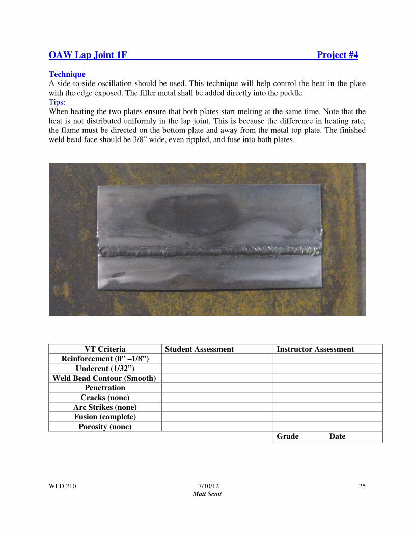
OAW Lap Joint 1F Project #4
Technique A side-to-side oscillation should be used. This technique will help control the heat in the plate
with the edge exposed. The filler metal shall be added directly into the puddle.
Tips:
When heating the two plates ensure that both plates start melting at the same time. Note that the
heat is not distributed uniformly in the lap joint. This is because the difference in heating rate,
the flame must be directed on the bottom plate and away from the metal top plate. The finished
weld bead face should be 3/8” wide, even rippled, and fuse into both plates.
VT Criteria Student Assessment Instructor Assessment
Reinforcement (0” –1/8”)
Undercut (1/32”)
Weld Bead Contour (Smooth)
Penetration
Cracks (none)
Arc Strikes (none)
Fusion (complete)
Porosity (none)
Grade Date

WLD 210 7/10/12
Matt Scott
26

WLD 210 7/10/12
Matt Scott
27
OAW T-Joint 1F Project #5
Technique A half moon oscillation can be used to put heat in both pieces of metal. The filler metal should
be added to the middle of the puddle. Too much heat, traveling to fast, or torch angle to low will
cause undercutting. Travel at a speed to produce a ¼” bead width, with 3/16” equal legs.
Tips:
The T-Joint has the same problem with uneven heating as the lap joint does. It is important to
hold the flame so that both plates melt at the same time. Another problem that is unique to the tee
joint is that a large percentage of the welding heat is reflected back on the torch. This reflected
heat can cause a properly cleaned and adjust torch to backfire or pop.
VT Criteria Student Assessment Instructor Assessment
Reinforcement (0” –1/8”)
Undercut (1/32”)
Weld Bead Contour (Smooth)
Penetration
Cracks (none)
Arc Strikes (none)
Fusion (complete)
Porosity (none)
Grade Date

WLD 210 7/10/12
Matt Scott
28
WLD 210 7/10/12
Matt Scott
29
Braze Welding
Braze Welding does not need capillary action to pull filler metal into the joint. Brazing and
Soldering are both classified by the American Welding Society a Liquid-solid phase bonding
processes. Liquid means that the filler metal is melted: solid means that the base material or
materials are not melted. The phase is the temperature at which bonding takes place between the
solid base material and the liquid filler metal. The bond between the base material and filler
metal is a metallurgical bond because no melting or alloying of the base metal occurs. If don
correctly, this bond results in a joint having four or five times the tensile strength of that of the
filler metal itself.
Soldering and brazing differ only in that soldering takes place at a temperature below 840degrees
F (450dgC) and brazing occurs at a temperature above 840degrees F (450dgC). Because only the
temperature separates the two processes, it is possible to do both soldering and brazing using
different mixtures of the same metals, depending upon the alloys used and their melting
temperatures.
Brazing is divided into two major categories, brazing and braze welding. In brazing, the parts
being joined must be fitted so that the joint spacing is very small, approximately .025l in. (.6mm)
to .002 in. (0.6 mm). This small spacing allows capillary action to draw the filler metal into the
joint when the parts reach the proper phase temperature.
Capillary action is the force that pulls water up into a paper towel, or pulls a liquid into a very
fine straw, Braze welding does not need capillary action to pull filler metal into the joint,
depending on joint design.
Some advantages of soldering and brazing as compared to other methods of joining include:
• Low temperature- since the base metal does not have to melt, a low-temperature heat
source can be used.
• May be permanently or temporarily joined--Since the base metal is not damaged,
parts may be disassembled at a later time b simply reapplying heat. The parts then can
be reused. However the joint is solid enough to be permanent.
• Dissimilar materials can be joined—It is easy to join dissimilar metals, such as copper
to steel, aluminum to brass, and cast iron to stainless steel. It is also possible to join
nonmetals to each other or nonmetals to metals. Ceramics are easily brazed to each
other or to metals.
• Speed of Joining
A. Parts can be pre-assembled and dipped or furnace soldered or brazed in large
quantities.
B. A lower temperature means less time in heating.
• Less chance of damaging parts—A heat source can be used that has a maximum
temperature below the temperature that may cause damage to the parts. With the
controlled temperature sufficiently low, even damage from unskilled or semiskilled
workers can be eliminated.

WLD 210 7/10/12
Matt Scott
30
• Slow rate of heating and cooling—because it is not necessary to heat a small area to
its melting temperature and then allow it to cool quickly to a solid, the internal
stresses caused by rapid temperature changes can be reduced.
• Parts of varying thickness can be joined—Very thin parts or thin part and a thick part
can be joined without burning or overheating them.
• Easy realignment—Parts can easily be realigned by reheating the joint and then
repositioning the part.
Physical Properties of the Joint
Tensile Strength
The tensile strength of a joint is its ability to withstand being pulled apart. A brazed joint can be
made that has a tensile strength four to five times higher than the filler metal itself.
Shear Strength
The shear strength of a joint is its ability to withstand a force parallel to the joint. For a solder or
braze join, the shear strength depends upon the amount of overlapping are of the base parts. The
greater the area that is overlapped, the greater the strength.
Ductility
Ductility of a joint is its ability to bend without failing. Most soldering and brazing alloys are
ductile metals, so the joint made with these alloys is also ductile.
Fatigue Resistance
The fatigue resistance of a metal is its ability to be bent repeatedly without exceeding its elastic
limit and without failure. For most soldered or brazed joints, fatigue resistance is usually fairly
low.
Fluxes General
• They must remove any oxides that form as a result of heating the parts.
• They must promote wetting.
• They should aid in capillary action.
The flux, when heated to its reacting temperature, must be thin and flow through the gap
provided at the joint. As it flows through the joint, the flux absorbs and dissolves oxides,
allowing the molten filler metal to be pulled in behind it. After the joint is complete, the flux
residue should be easily removable.
WLD 210 7/10/12
Matt Scott
31
Brazing Methods General
Soldering and brazing methods are grouped according to the method with which heat is applied:
Torch, furnace, induction, dip, or resistance.
It is preferable to use on of the fuel gases having a higher heat level in the secondary flame this is
where acetylene brazing comes in. The oxyacetylene flame has a higher temperature near the
inner cone, but it has little heat in the outer flame. This often results in the parts being overheated
in a localized area.
Some advantages of using a torch include the following:
• Versatility—Using a torch is the most versatile method. Both small and large parts in a
wide variety of materials can be joined with the same torch.
• Portability—A torch is very portable. Anyplace a set of cylinders can be taken or any
where the hoses can be pulled into can be soldered or brazed with a torch.
• Speed – The flame of the torch is one of the quickest ways of heating the material to be
joined, especially on thicker sections.
Some disadvantages of using a torch include the following
• Overheating—When using a torch, it is easy to overheat or burn the parts, flux, or filler
metal.
• Skill—A high level of skill with a torch is required to produce consistently good joints.
• Fires—It is easy to start a fire if a torch is used around combustible materials.
JOINT DESIGN General
The spacing between the parts being joined greatly affects the tensile strength of the finished
part. As the parts are heated, the initial space may increase or decrease, depending upon the joint
design and fixtures. The changes due to expansion can be calculated, but trial and error also
works.
The strongest joints are obtained when the parts use lap or scarf joints where the joining area is
equal to three times the thickness of the thinnest joint member. The strength of a butt joint can be
increased if they are being joined can be increased. Parts that ¼” in.(6mm) thick should not be
considered for brazing or soldering if another process will work successfully.
Joint preparation is equally as important to successfully be brazed.

WLD 210 7/10/12
Matt Scott
32
Braze Welding Information Sheet
When brazing apply flame to the joint area, heating both edges or surfaces to a dull red color. Do
not over heat the base metal. If the base metal becomes to hot, the zinc in a brass filler rod will
burn off and this may produce toxic fumes. Too much heat is indicated when the joint area turns
copper in color. Some brazing flux compounds are specially formulated so they melt when
proper brazing temperature is reached.
While heating the metal, keep the end of the brazing rod in or near the torch flame to preheat the
rod. This helps the rod melt more easily when touched to the hot material that you are going to
apply filler to. Then the base metal has been heated to a dull red color bring the brazing rod into
contact with the dull red area. Maintain uniform heating in the base metal by using a smooth,
uniform torch motion. The brazing rod will quickly melt and flow over or between the joint
surfaces.
The width of braze welding bead is determined by the width of the portion of the base metal that
is heated enough to melt the filler metal. The filler metal will only flow on and adhere to the base
metal surface that is free of oxides and is at the correct temperature. Move the torch flame in a
particular direction causes the filler metal to follow in the same direction. As a guideline, the
width of the braze weld bead should be just a little wider than a normal fusion weld on the same
thickness of metal.
When braze welding, move the weld bead along the joint at a uniform rate of travel, as you
would the molten puddle when gas welding, increase travel speed slightly. Do not hold the flame
as close in weld brazing as you would in gas welding. Holding the flame to close will cause the
base material to become to hot and will increase the width of the weld bead. Flashing the torch
away from the weld puddle the metal cools and the bead will narrow. You may move and change
the work distance as necessary to obtain the desired bead width. The finished welded joint should
have the appearance of adequate adhesion to the base metal. The filler metal should seep all
through the brazed joint and appear underneath. On braze welded joints, the filler metal should
completely fill the joint area and have a smooth appearance.
A white deposit of (like white soot) along the toe of the brazed joint indicates an overheated
joint. Discoloration of the braze filler metal in the joint also indicates overheating. A good
welded joint should show the color of the filler metal itself.

WLD 210 7/10/12
Matt Scott
33
Fluxes
Various metals require different types of fluxes. Most fluxes fall into one of several chemical
groupings, which include borates, boric acid, alkalis, fluorides, and chlorides. Manufacturers
have their own trade names for fluxes to be used with different metals. For the best results follow
the manufacturer’s recommendations for selection and application. Fluxes are available in many
forms, such as solids, powders, pastes, liquids, sheets, rings and washer. They are also available
mixed with the filler metal, inside the filler metal, or on the outside of the filler metal.
Purposes of Fluxes:
• Flux chemically cleans the base metal.
• Flux prevents oxidation of the filler metal.
• Flux floats and removes the oxides already present.
• Flux increases the flow of the filler metal.
• Flux increases the ability of the filler metal to adhere to the base metal.
• Flux brings the filler metal into immediate contact with the metals being joined.
• Flux permits the filler metal to penetrate the pores of the base metal.
Braze Filler Rods
Characteristics of filler rods for braze welding:
A. Filler rods consist of copper alloys containing about 60 percent copper and 40 percent
zinc, which:
1. Produce a high tensile strength.
2. Increase ductility.
B. Filler rods contain small quantities of tin, iron, manganese, and silicon, which help to:
1. Deoxidize the weld metal.
2. Decrease the tendency to fume.
3. Increase the free-flowing action of the molten metal.
4. Increase the hardness of the deposited metal for greater wear resistance.
C. Filler rods should be cleaned with emery cloth before use, ones without flux already on.

WLD 210 7/10/12
Matt Scott
34
TROUBLESHOOTING TIPS FOR BRAZING
1. Increased amount of flux.
IF BRAZING ALLOY
2. Roughened surfaces produced by shot
blasting, pickling, etc.
DOESN'T WET SURFACES,
BUT·"BALLS UP"
INSTEAD OF RUNNING
INTO THE JOINT, TRY:
3. Removing surfaces of cold-drawn and
cold-rolled bar stock by machining or
grinding.
4. Pickling parts to remove surface oxides.
5. Placing the assembly in a different posit/on,
such as on an incline. to encourage brazing
alloy to run into joints.
Look for:
6. Impurities in the acid used for pickling, grit
from shot blasting, lubricant from various
machining operations, etc.
1. More time for heating.
IF BRAZING ALLOY 2. Higher temperature.
DOESN’T CREEP 3. A looser fit, or a tighter one.
THROUGH THE JOINT,
EVEN THOUGH IT MELTS
AND FORMS A FILLET, TRY:
4. Flux applied to both alloy and parent metals
within and around joint.
5. More thorough cleaning of parts before
assembly.
Look for:
1. Interruption of capillarity within the joint,
such as by a gap.
2. Line contact within the joint instead of a
uniform fit.
3. Freezing of brazing alloy caused by
excessive pick-up of the parent metal.
4. Flux breakdown due to too much heat.
5. Improper or insufficient cleaning.

WLD 210 7/10/12
Matt Scott
35
1. Excessively tight press fit, which stretches
outer member beyond its elastic limit.
IF JOINT OPENS DURING BRAZING, 2. High coefficient of expansion.
ALTHOUGH IT WAS TIGHT
WHEN ASSEMBLED, LOOK FOR:
3. Unequal expansion of parts due to unlike
metals or sections.
4. Release of residual stresses (stresses from
cold-working) in certain parts.
5. An unsupported section which might sag at
high temperatures.
6. Porosity in parent metals caused by burning
through it when tack welding parts
together.
IF BRAZING ALLOY MELTS,
BUT RETAINS ITS ORIGINAL
FORM WITHOUT FLOWING, TRY
1. Coating the brazing alloy with flux before
using and applying flux generously to
parent metals within and around the joint.
2. Mechanically or chemically cleaning the
brazing alloy, if noticeably oxidized before
using.
1. Providing a reservoir at the joint into which
brazing alloy can flow.
IF BRAZING ALLOY FLOWS
AWAY FROM, INSTEAD OF INTO, THE
JOINT, TRY:
2. Placing the assembly in a different position,
such as on an incline, to encourage brazing
alloy to run into joints.
3. Placing brazing alloy in strategic position
above the joint if axis is vertical, or against the
shoulder if axis is horizontal, so it will creep
into the joint.
4. A light copper plating on surfaces.
Look for: 5. Burrs at edges of punched holes, or other
obstacles over which the brazing alloy might
not creep.
(Information courtesy of United Wire & Supply Corp.)

WLD 210 7/10/12
Matt Scott
36
TB Lap-Joint 1F (Braze Welding) Project #6
Technique: Heat area to be welded to a dull red, concentrate on lower base metal then with a slightly circular
motion, move the flame up and heat the upper plate when both pieces have reached a dull red.
Position the flame in the center of joint, then insert filler rod add a molten drop of bronze to joint
pulling filler rod just slightly out of the flame and in the direction of travel. Repeat as necessary
until weld bead and joint has been completely welded.
Tips;
Control heat input on plate. Flashing torch will aid in controlling heat input. Add filler in middle
of puddle. Flashing and adding filler will help control size of weld bead. Weld bead should not
be larger than 3/8”in. in width.
VT Criteria Student Assessment Instructor Assessment
Reinforcement (0” –1/8”)
Undercut (1/32”)
Weld Bead Contour (Smooth)
Penetration
Cracks (none)
Arc Strikes (none)
Fusion (complete)
Porosity (none)
Grade Date

WLD 210 7/10/12
Matt Scott
37

WLD 210 7/10/12
Matt Scott
38
TB Lap-Joint 2F (Braze Welding) Project #7
Technique: Hold the torch at approximately 45deg. work angle and a 45deg. travel angle and move down
until flame is about 1/8 of an inch from surface at the very corner of joint. Concentrate heat on
lower plate and then move to the upper plate in a circular motion until both plates have reached a
dull red. Insert filler rod into flame drop a portion of filler into dull red area, start circular motion
of flame move torch in direction of travel adding additional filler as needed.
Tips;
Control heat input on plate. Oscillating torch will aid in controlling heat input. Add filler in
middle of puddle. Oscillating and adding filler will help control size of weld bead. Weld bead
should not be larger than 3/8”in. in width.
VT Criteria Student Assessment Instructor Assessment
Reinforcement (0” –1/8”)
Undercut (1/32”)
Weld Bead Contour (Smooth)
Penetration
Cracks (none)
Arc Strikes (none)
Fusion (complete)
Porosity (none)
Grade Date

WLD 210 7/10/12
Matt Scott
39
WLD 210 7/10/12
Matt Scott
40
G.T.A.W. Introduction
GTAW (Gas Tungsten Arc Welding), TIG (Tungsten Inert Gas), also sometimes referred to as “Heliarc.” Heliarc
was a trade name of one of the first manufactures of the GTAW power sources. The GTAW process was developed
in the period of 1940-1960 and rapidly became an indispensable welding process.
The complete name for the process is:
Gas Refers to the gas substance (usually argon, helium or a mixture there of) that blankets the
electrode, molten puddle and stabilizes the arc. This gas is inert which means that the gas
will not combine chemically with other elements and is nonflammable.
Tungsten Refers to the non-consumable electrode that conducts electric current to the arc.
Arc Indicates that the welding is done by an electric arc rather than by the combustion of a
gas.
Welding Coalescence is the fusion or growing together of grains which is produced by heating
with an arc between a tungsten electrode and the work. A filler material may or may not
be added.
Advantages: 1. GTAW can make high quality welds with almost all metals and alloys.
2. No flux is required and finished welds do not have to be cleaned.
3. The arc and weld pool are clearly visible to the welder.
4. There is no filler metal carried across the arc so there is no spatter.
5. Welding can be performed in all positions.
6. There is no slag produced that might be trapped in the weld.
7. There is minimum distortion of the metal near the weld. The heat is concentrated in a small area
resulting is a small heat-affected zone.
8. In the chemical composition, the weld is usually equal to the base metal. It is usually stronger,
more resistant to corrosion, and more ductile than welds made by other processes.
Disadvantages:
1. More complex and expensive equipment is required.
2. Higher operating cost (Argon gas and tungsten electrodes).
3. Higher degree of manipulative skill is required.
4. Extensive material preparation required. Welding area must be free of contaminants such as oil,
paint, rust, etc.
5. Limited area of operations (nearly ideal conditions are required compared to other welding
processes).
6. Slower deposit rates than other processes.

WLD 210 7/10/12
Matt Scott
41
Uses of GTAW
The GTAW process is used when high quality and purity of the weld have priority over welding speed. GTAW is
used in many welding manufacturing operations, primarily on thinner materials where metal finishing is not desired.
It is very useful for maintenance and repair work, for die castings and unusual metals. GTAW is widely used for
joining thin wall tubing and for making root passes on pipe joints.
The aircraft industry is one of the principle users of this process on such materials as aluminum, magnesium,
titanium, and stainless steel. Products produced using GTAW include: space vehicles, rocket and jet engines,
nuclear power industries, tanks, boilers and medical equipment.
INTRODUCTION TO ALUMINUM
PROPERTIES AND WELDABILITY OF ALUMINUM
Aluminum has a number of properties that make welding it different from welding steels. These are:
1. Aluminum oxide surface coating (melting temperature of approximately 3,300F).
2. High thermal conductivity
3. High thermal expansion
4. Low melting point 1100 to 1200 F depending upon alloy content.
5. The absence of color change as temperature approaches melting points.
6. The rapid formation of oxides in aluminum make material preparation a critical step in the welding
procedures. After the surface is cleaned, welding should be performed within eight hours to ensure weld
quality. Surface should be cleaned prior to welding and then welded immediately.
7. Aluminum conducts heat three to five times faster than steel. This means that higher currents are required
during welding even though the melting point of aluminum is less than half that of steel. Because of the
high thermal conductivity, preheat is often used on thicker sections. The high heat conductivity of
aluminum is helpful in that heat leaves the weld area quickly, causing the weld pool to solidify rapidly.
This helps hold the weld metal in position and makes all position welding easier.
8. The thermal expansion of aluminum is twice that of steel. In addition, aluminum welds decrease about 6%
in volume when solidifying. This may cause distortion and cracking.
9. Aluminum is light weight, very ductile, malleable, non-magnetic, highly reflective, and may be heat
treated, work hardened, and alloyed with other elements to improve its properties for a wide variety of
applications.

WLD 210 7/10/12
Matt Scott
42
Tungsten Electrodes Tungsten and tungsten alloys are the choice for electrode material because tungsten has the
highest melting point of all metals (6,170° F) (3,410° C). Tungsten also offers low electrical
resistance, good heat conductivity, and the ability to easily emit electrons. Four classes of
tungsten electrodes have been standardized by the A.W.S. (American Welding Society). Shown
below are A.W.S. classifications and color codes for the end of the electrodes.
A.W.S. Classification* Type End Color
E.W.P. Pure Tungsten green
EWTH-1 1% Thorium added yellow
EWTH-2 2% Thorium added red
EWZr 50% Zirconium added brown
Available diameters 0.020 to 0.250 inch (0.5 to 6.4 mm).
Available lengths 3 to 24 inch (76 to 610 mm).
*AWS Classification System for Tungsten:
EWTH-2 - E - electrode
W - atomic symbol for
Tungsten (Wolfram)
Th2- alloy containing 2%
Thorium
EWP -
W – tungsten (Wolfram)
P – pure
Pure tungsten is generally used for AC welding. The zirconium type is also excellent for AC.
Thoriated tungsten electrodes are available for direct current straight polarity welding. The
addition of thorium increases the current carrying capacity of the tungsten.
Tungsten selection
The material to be welded and the type of current used are the determining factors in the
selection of type of tungsten. In welding of mild steel, use D.C.S.P.(Direct Current Straight
Polarity) and a 2% Thoriated tungsten (EWTh2). Selection of tungsten diameter will depend
on the current range being used. The following chart recommends current ranges for tungsten
diameters.
Typical current ranges for tungsten electrodes, DCSP, Argon shielding gas.
Current Range (Amp.) Electrode Diameter (in.)
5 – 20 0.020
15 – 80 0.040
70 – 150 1/16
150 – 250 3/32
250 – 400 1/8
350 – 500 5/32
500 – 750 3/16
750 – 1000 ¼

WLD 210 7/10/12
Matt Scott
43
Tungsten Preparation
A sharpened point is used with direct current straight polarity (D.C.S.P). for carbon steels.
Grinding should be done on a fine-grit hard abrasive wheel. To prevent contaminating the
tungsten, this wheel should not be used to grind any other material. Use ONLY the grinder
designated for tungsten only.
The tungsten should be ground vertically so the grind lines are in the same direction as current
flow. This helps avoid spitting of tungsten particles into the weld. Light pressure only should be
applied during grinding to avoid overheating of the tungsten. Blue spots are an indication of
overheating.
ALWAYS WEAR EYE PROTECTION WHEN SHARPENING A TUNGSTEN!!! Tungsten
electrodes are very brittle and easily shattered.
The condition of the tungsten tip is a very important factor in successful weld results. If the
tip becomes contaminated during welding, it must be re-sharpened.

WLD 210 7/10/12
Matt Scott
44
Shielding Gases
The type of shielding gas used in GTAW is inert. Inert means that the gas does not form
compounds with other elements and is nonflammable. Argon and helium are two inert shielding
gases used in GTAW.
Argon is most commonly used. It is readily available, heavier than helium and slightly heavier
than air. This provides a more efficient arc shielding at lower flow rates. Argon is also better for
arc starting and operates at lower arc voltage.
Helium provides higher arc voltage resulting in deeper penetration than argon. It is also possible
to weld at higher speeds with helium. Helium is lighter than Argon or air and tends to float away
from the weld zone so higher flow rates are required. In some cases argon and helium are mixed
together for a particular welding application.
Shielding gas may be supplied from cylinders or a manifold system. A combination regulator
and flow meter is usually used. The regulator reduces the high pressure of the cylinder to a
usable working pressure. The flow meter provides uniform flow of shielding. It is calibrated to
show flow in cubic feet per hour (c.f.h.).
Flow should be adjusted by turning the adjusting knob; reference the flow meter to determine
whether reading the top, middle, or bottom of the ball when setting the flow. Because of the
difference in gas densities, flow meters must be designed for the specific gas being used.
Flow meter adjusting knob
Cylinder Pressure Gage
Cylinder on/off valve
Safety valve for the
cylinder
Cylinder with flow meter
For your practice, in our shop, 15 to 20 cubic feet per hour (c.f.h.) of argon is usually a good
working range. Some factors that may affect the flow rate are listed below:
1. Type of shielding gas 4. Size of cup
2. Type and design of weld joint 5. Size of puddle
3. Cup to work distance 6. Position of welding
7. Air drafts in the welding area

WLD 210 7/10/12
Matt Scott
45
Filler Metal Composition
As in all welding, the filler material must be similar in composition but not necessarily identical
to the metal being welded.
Mild steel identifies those steels whose carbon content is in the range of 0.03% to .30%. These
are also known as low carbon steels or plain steels. Mild steel is produced in greater quantities
than all other steels combined. The weldability and machinability of mild steel is excellent. It is
the most widely used and can be found in structures fabricated by welding such as bridges, ships,
tanks, pipes, buildings, railroad cars, automobiles, and many more. Besides carbon, steel is
made up of iron, silicon, sulfur, phosphorus, and manganese. Carbon is the most important
alloying element in steel. An increase of as little as 0.1 percent carbon can change all of the
properties of steel.
Selection of filler size will vary with joint requirements and current range. A good working rule
is to select the same diameter filler as the tungsten you are using.
Note: see AWS Standards A5.18 and A5.28 for a description of each classification of filler
material.
Filler metal identification

WLD 210 7/10/12
Matt Scott
46
GTAW Power Sources
The welding power source used for GTAW is a constant current type of output. GTAW power sources may also be
used for SMAW (Shielded Metal Arc Welding “stick”). There are a variety of types and models of GTAW power
sources. Power source controls vary greatly from one manufacturer to another and from one model of machine to
another. New technology is rapidly changing welding power sources, therefore it is necessary to study in greater
detail the many adjustments available on the “state of the art” power sources in use today. We have utilized the
owners manual information to review the controls on the different power sources. For the purpose of this course, the
focus will be on the power source controls that will be used during your Aluminum.
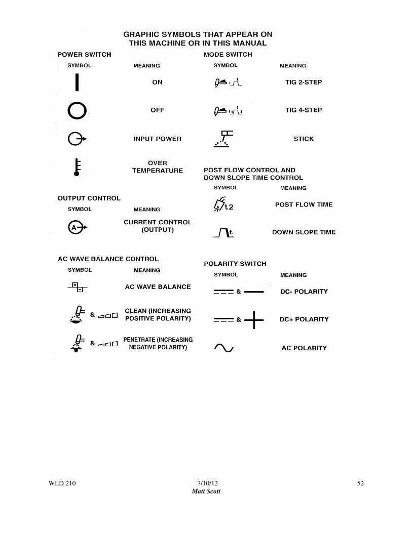
One of the many advances in welding power sources is the use of graphic symbols to identify controls. This
provides communication on an international level. Please see the chart of graphic symbols following the power
source information.
An important outcome of your training is to develop knowledge and skills in the operation of a variety of GTAW
power sources. This course will introduce the basic functions of the following GTAW power sources;
• Lincoln Idealarc 300 • Lincoln Square Wave 255
• Lincoln Square Wave 275
• Lincoln Square Wave 355
• Miller Syncrowave 350LX
• Miller Syncrowave 250

WLD 210 7/10/12
Matt Scott
47
Standard Power Source Controls
Current Selector Switch
This allows you to select the welding current desired. The type of material to be welded determines the current
choice. Alternating Current High Frequency (ACHF) is the current choice for aluminum.
Coarse Current Range Selector
This adjustment allows you to select a wide current range usually labeled simply Low, Medium, and High with the
minimum and maximum amperage available within each range listed below the range setting. Most of the newer
machines have a single wide current range instead of low, medium and high, this allows adjustment of the full range
of the current available
Fine Current Adjustment
This adjustment allows you to select what percentage of the coarse range you wish to use. Usually a dial labeled 1
through 10. For example, if you have selected low range and your fine adjustment is set at 5, your available current
will be 50% of the maximum current listed for low range.
Standard/Remote Contactor Control Switch When a remote contactor, such as a foot peddle for GTAW is being used, this switch must be in the "remote"
position. The switch should be in the "standard" position when using the power source for SMAW.
Remote Amperage Control Receptacle This receptacle is provided for connecting a remote hand or remote foot control. This allows the operator to have
amperage control while welding. When the foot control is completely depressed your welding current will be the
maximum available as determined by coarse and fine current settings.
Post Flow This adjustment is an after timer for the flow of gas, sometimes labeled "post purge" or "after flow." This adjustment
controls the length of time that the gas flows after the arc is broken. The flow of gas after the arc is broken protects
the tungsten from atmospheric contamination as it cools, and protects the molten weld pool as it solidifies.
High Frequency Switch (also known as “Spark”) The high frequency current serves two purposes in GTAW. It provides a non-touch start in arc initiation and
stabilizes the arc during AC welding applications. The switch has three positions,
Continuous: Sometimes labeled "ON." In this position the high frequency is present all of the time during
welding. When welding with AC it is necessary to have continuous high frequency to stabilize the
alternating current.
Off: Eliminates the presence of the high frequency. This setting is used when the power source is used for
SMAW (stick).
Start: In this position the high frequency is present only to initiate the arc, once the arc is established it
shuts off. This position is the choice when welding with DCSP.
High Frequency Adjustment This control is a dial that allows you to increase or decrease the strength of the high
frequency current. Sometimes labeled High Frequency Intensity.
Power Switch This control turns the welding machine on and off.
Tig and Stick Switch This control allows the welder to change back and forth between GTAW and SMAW.

WLD 210 7/10/12
Matt Scott
48
Lincoln Idealarc 300
WLD 210 7/10/12
Matt Scott
49
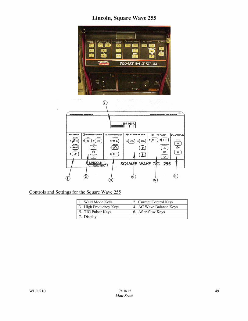
Lincoln, Square Wave 255
Controls and Settings for the Square Wave 255
1. Weld Mode Keys 2. Current Control Keys
3. High Frequency Keys 4. AC Wave Balance Keys
5. TIG Pulser Keys 6. After-flow Keys
7. Display

WLD 210 7/10/12
Matt Scott
50
New Advanced Power Source Controls
Control Panel Keys for the Lincoln Square Wave 255
The keys are grouped into six areas, described below. Some areas are active in both TIG and Stick, while others are
active in TIG only. The red indicator lights identify which functions are active.
1. WELD MODE KEYS: These keys select the Weld mode desired, as the graphic symbols indicate the TIG 2-
Step mode is selected when using a Foot Amptrol (foot operated remote current control), the TIG 4-Step is
selected when using a Hand Amptrol ( hand operated remote current control, usually mounted on the torch).
The third mode is selected when using the power source for Stick welding.
2. CURRENT CONTROL: This area contains the Local/Remote keys as well as the Amps Up/Amps Down keys.
The up/down keys are used to adjust amperage from 5 to 315 amps. The “Local” current control allows the
current to be adjusted only with the Amps up/Amps down keys. The “Remote” current control is automatically
activated when using the TIG 2-Step and TIG 4-Step modes.
3. HIGH FREQUENCY: These keys are active in the TIG mode only. Select “Start Only” when using Direct
Current straight polarity. Select “Continuous” when welding with Alternating Current. “Off” will automatically
be selected when welding in the Stick mode.
4. AC WAVE BALANCE: These keys are active in the AC TIG mode only. They are used to set the amount of
cleaning and/or penetration. Auto Balance automatically sets the AC Wave balance according to the welding
current.
5. TIG PULSER: These keys are active in the TIG mode only. The On/Off keys turn the pulse option on and off.
The Pulses Per Second keys adjust the pulsing frequency up and down, from 0.5 to 10 pulses per second. The
background current (the welding current at the low point of the pulse cycle) is automatically adjusted from 40%
to 60% of the peak current (the welding current selected). The ratio between the time spent at peak current
verses, the time spent at the background current is fixed at 50%.
6. AFTERFLOW: These keys are active in the TIG mode only. These keys adjust the length of time the gas flows
after the arc is extinguished.

WLD 210 7/10/12
Matt Scott
51
Lincoln, Square Wave TIG 275
Controls for the Lincoln Square
Wave TIG
Controls for the Lincoln Square Wave TIG 275
1. Current Control Knob 2. AC Wave Balance Knob
3. Post Flow Knob 4. Down Slope Time Knob
5. Mode Switch 6. Trimmer Potentiometer
7. Digital Ammeter 8. Digital Voltmeter
9. Thermal Protection
Light
10. Power Switch
11. Polarity Switch 12. Electrode Connection
13. Work Connection 14. Remote Control Amphenol
15. Water Solenoid
Note: The Lincoln Square Wave 275 does not have a separate high frequency switch. The high frequency is built into the
polarity switch.
WLD 210 7/10/12
Matt Scott
52

WLD 210 7/10/12
Matt Scott
53

WLD 210 7/10/12
Matt Scott
54
Lincoln, Square Wave TIG 355
Miller, Syncrowave 350LX

WLD 210 7/10/12
Matt Scott
55
Controls and Settings for the Miller Syncrowave 350LX
1. Process Control 2. Current Control
3. Output Control 4. Start Mode Button
5. Voltmeter 6. Ammeter
7. Amperage Adjustment
Control
8. Output Selector Switch
9. Power Switch (on/off) 10. Post Flow Time Control
11. Pre Flow Time Control 12. Balance/Dig Control
13. Pulser On/Off Switch 14. Back Ground Amperage
Control
15. Pulses Frequency Control 16. Peak Time Control
17. Sequence Controls
(Optional)
18. High Frequency Control

WLD 210 7/10/12
Matt Scott
56
Symbols and Definitions for the Miller Syncrowave 350LX and Lincoln Squarewave Tig 355

WLD 210 7/10/12
Matt Scott
57
Miller, Syncrowave 250
Controls and Setting for the Miller Syncrowave 250 1. Ammeter 2. Voltmeter
3. High Frequency Switch 4. Output (contactor) Switch
5. Amperage Control Switch 6. Spot Time Switch and Control
7. Pre-flow Time Control 8. AC Balance Control
9. Crater Time Switch and Control 10. Amperage Adjustment Control
11. Arc Force (dig) Switch and Control 12. Post-flow Time and Control
13. High Temperature Shutdown Light 14. Power Switch and Pilot Light
15. Output Selector Switch 16. High Frequency Control

WLD 210 7/10/12
Matt Scott
58
Symbols and Definitions for the Miller Syncrowave 250

WLD 210 7/10/12
Matt Scott
59
TORCH ASSEMBLY
The Gas Tungsten Arc Welding torch functions as an: electrode holder; a conduit for the shielding gas and coolant
if used; and for a conductor of the welding current. Torches are available in a variety of sizes and shapes. Torches
are rated by the maximum amperage they can carry. For example, air cooled torches are normally rated at about 150
amperes. This is the maximum welding current that can be safely used. Some water-cooled torches are rated up to
500 amperes.
The typical GTAW torch has several parts that include: 1. The cap seals the back of the torch and tightens to hold tungsten in place. Caps are available in a
variety of sizes. The one shown is for a seven inch long tungsten.
2. "O" ring - fits on the cap to insure an air tight seal on the back of the torch.
3. The tungsten is placed inside the torch. Tungstens are available in a wide variety of diameters
and lengths.
4. Electrode collet
The collet holds the tungsten in place. The collet size must be the same as the tungsten diameter.
For example, if you are using a 1/16” diameter tungsten you will need a 1/16” collet.
5. Collet Body
The collet body holds the collet in position and also disperses the shielding-gas into the gas cup.
Some torches have universal collet holders. The torches in our shop do not. The collet and collet
body must be the same size as your tungsten diameter.
6. Torch body
Torch bodies are available in a variety of sizes and shapes. They are threaded in the front and
back for assembly.
7. Gas nozzle
More commonly known as "gas cup," it directs the shielding gas over the weld pool. Cups are
usually made of a high heat ceramic and are available in many sizes. Cup size will vary with joint
type for accessibility and tungsten diameter. Your cup should be 4 to 6 times larger than tungsten
diameter. Cup sizes are measured in 1/16” of an inch. For example, a number 4 cup would
measure 4/16” inch (1/4”) in diameter and would be suitable for up to 1/16” diameter tungsten.

WLD 210 7/10/12
Matt Scott
60
Tungsten Electrodes
Tungsten and tungsten alloys are the choice for electrode material because tungsten has the
highest melting point of all metals (6,170° F) (3,410° C). Tungsten also offers low electrical
resistance, good heat conductivity, and the ability to easily emit electrons. Four classes of
tungsten electrodes have been standardized by the American Welding Society (AWS). Shown
below are AWS classifications and color codes for the end of the electrodes.
AWS Classification* Type End Color
E.W.P. Pure Tungsten green
EWTH-1 1% Thorium added yellow
EWTH-2 2% Thorium added red
EWZr 50% Zirconium added brown
Available diameters 0.020 to 0.250 inch (0.5 to 6.4 mm).
Available lengths 3 to 24 inch (76 to 610 mm).
*AWS Classification System for Tungsten:
EWTH-2 - E - electrode
W - atomic symbol for
tungsten (Wolfram)
Th2- alloy containing 2%
Thorium
EWP - E- electrode W – tungsten (Wolfram)
P – pure
Pure tungsten is generally used for AC welding. The zirconium type is also excellent for AC. Thoriated tungsten
electrodes are available for direct current straight polarity welding. The addition of thorium increases the current
carrying capacity of the tungsten.
Tungsten selection
The material to be welded and the type of current used are the determining factors in the
selection of type of tungsten. When welding aluminum use ACHF with a pure tungsten
(EWP). The selection of tungsten diameter will depend on the current range being used
and the thickness of the metal to be welded. The following chart recommends current
ranges for tungsten diameters.
Typical current ranges for tungsten electrodes, ACHF, with Argon shielding gas
Current Range (Amp.) Electrode Diameter (in.)
5 – 20 0.020
15 – 80 0.040
70 – 150 1/16
150 – 250 3/32
250 – 400 1/8
350 – 500 5/32
500 – 750 3/16
750 – 1000 ¼

WLD 210 7/10/12
Matt Scott
61
Recommended. ACHF Current Ranges for EWP
Electrode Diameter Current Range
(Amperage)
0.10” 8-15
0.20” 10-20
0.40”
15-50
1/16”
40-140
3/32”
90-160
1/8”
140-210
5/32”
180-275
3/16”
240-340
¼”
280-490

WLD 210 7/10/12
Matt Scott
62
Chart Reading for Welders
Name: _________________________________ Date: ____________________
Look at the charts in your packet entitled: ‘Recommended Procedure for GTAW of Aluminum’
Answer the following questions about this chart.
1. What is the approximate helium flow rate for a plate that is 3/8 inch thick when you are using 250-320
amps?
2. What is the filler rod diameter for ¼ inch plate thickness?
3. In what position(s) can you weld a plate that is 1/16inch thick?
4. In what position(s) can you weld a plate that is 1 inch thick?
5. What is the recommended argon gas flow for a ½ inch plate thickness?
6. What plate thickness and electrode diameter are recommended with an alternating current setting of 425
amps?
7. What is the recommended number of passes on a 3/8 inch plate when the argon gas flow is 35 c.f.h.?
8. Define the following units:
a. c. f. h.
b. amp
c. diameter

WLD 210 7/10/12
Matt Scott
63
GTAW Flat Position Corner Joint (Fuse Weld) Project #8 Objectives of this welding exercise are:
• To practice set up and adjustment of the equipment.
• To develop consistency in control of travel speed and arc length.
• Your goal is to fuse the edge surfaces resulting in a smooth rounded contour on all sides of
the joint. Note that when “fuse” welding no filler material is added.
Cause and effect factors
Amperage Too high = undercutting, or melting holes through the work
Too low = lack of fusion on the edges of the joint
Travel Speed Too slow = excessive heat, irregular shape, burning holes
Too fast = weld does not wrap the edges of the plates leaving them sharp and jagged.
Arc length Too short = touching the tungsten to the work, contaminating the tungsten and the work.
Too long = undercutting, and can result in loss of gas coverage creating porosity.
VT Criteria Student Assessment Instructor Assessment Weld Size
Undercut
Weld Contour
Penetration
Cracks
Arc Strikes
Fusion
Porosity
Overlap
Completed GRADE

WLD 210 7/10/12
Matt Scott
64

WLD 210 7/10/12
Matt Scott
65
GTAW Horizontal Lap Joint Project #9 Objectives of this welding exercise are:
• To practice set up and adjust of the equipment for a different application.
• To develop consistency in your ability to control travel speed and arc length.
• To develop the ability to add filler material to the weld pool.
VT Criteria Student Assessment Instructor Assessment
Weld Size
Undercut
Weld Contour
Penetration
Cracks
Arc Strikes
Fusion
Porosity
Overlap
Completed GRADE

WLD 210 7/10/12
Matt Scott
66

WLD 210 7/10/12
Matt Scott
67
GTAW Horizontal T Joint Project #10 Objectives of this welding exercise are:
• To practice set up and adjust of the equipment for a different application.
• To develop consistency in your ability to control travel speed and arc length.
• To develop the ability to add filler material to the weld pool.
VT Criteria Student Assessment Instructor Assessment Weld Size
Undercut
Weld Contour
Penetration
Cracks
Arc Strikes
Fusion
Porosity
Overlap
Completed GRADE

WLD 210 7/10/12
Matt Scott
68

WLD 210 7/10/12
Matt Scott
69
GTAW - Aluminum Projects
CLASSIFICATION OF ALUMINUM
Aluminum alloys are broadly classified as castings or wrought material. Our focus will be on the wrought alloys.
This group includes alloys that are designed for mill products whose final physical forms are obtained by working
the metal mechanically, rolling, forging, extruding, and drawing. These products include: sheet, plate, wire, rod,
bar, tube, pipe, forgings, angles, structural channels, and rolled and extruded shapes.
The Aluminum association has designed a four digit index system for designating wrought
aluminum and its alloys.
The first digit identifies the alloy group:
Aluminum Alloy Designation
Aluminum - 99.0% 1xxx
Copper 2xxx
Manganese 3xxx
Silicon 4xxx
Magnesium 5xxx
Magnesium and Silicon 6xxx
Zinc 7xxx
Other elements 8xxx
Unused series 9xxx
Second digit indicates modification or impurities, last two digits indicate minimum aluminum percentage, i.e. 1075
is 99.75% pure aluminum.
Example:
6061 Aluminum
6 = Magnesium and Silicon is the major alloy group
0 = no modifications or significant impurities
61 = percent aluminum

WLD 210 7/10/12
Matt Scott
70
MAJOR ALUMINUM ALLOYS AND THEIR APPLICATIONS
Alloy
Series
Description of Major Alloying
Element
Typical
Alloys
Typical Additions
1xxx 99.00% Minimum 1350 Electrical conductor
Aluminum 1060 Chemical equipment, tank cars
1100 Sheet metal work, cooking utensils,
decorative
2XXX Copper (Al-Cu)
2011 Screw Machine parts
2219 Structural, high temperature
(Al-Cu-g)
2014 Aircraft structures and engines, truck frames
and wheels
2024
2618
3XXX Manganese 3003 Sheet metal work, chemical
3004 Equipment, storage tanks
4XXX Silicon 4032 Pistons
4043 Welding electrode
4343 Brazing Alloy
5XXX Magnesium 5005 Decorative, architectural
5050 Anodized automotive-trim
5052 Sheet metal work, appliances
5657
(>3%Mg)
5083 Marine, welded structures
5086 Storage tanks, pressure
5454 Vessels, armor plate
5456 Cryogenics
6XXX Magnesium and Silicon 6061 Marine, truck frames
6063 Bodies, structures, architectural, furniture
7XXX Zinc (Al-Zn-Mg)
7004 Structural, cryogenics, missiles
7005 (Al-An-Mg-Cu)
7001 High strength structural
7075 Aircraft
7178

WLD 210 7/10/12
Matt Scott
71
ALUMINUM ALLOYS
A temper designation system is used to indicate the condition of a product. It is based on the sequence of basic
treatments used to produce the desired mechanical properties. This designation follows the alloy designation.
Subsequent divisions of the basic letter tempers are indicated by one or more digits following the letter. These digits
designate a specific sequence of basic treatments.
BASIC TEMPER DESIGNATIONS FOR ALUMINUM ALLOYS
F As-Fabricated
O Annealed
H1 Strain hardened only
H2 Strain hardened and partially annealed
H3 Strain hardened and thermally stabilized
W Solution heat-treated
T1 Cooled from an elevated temperature shaping process and naturally aged
T2 Cooled from an elevated temperature shaping process, cold worked and naturally aged
T3 *Solution heat-treated, cold worked, and naturally aged
T4 Solution heat-treated and naturally aged
T5 Cooled from an elevated temperature shaping process and then artificially aged
T6 Solution heat-treated and then artificially aged
T7 Solution heat-treated and stabilized
T8 Solution heat-treated, cold worked, and then artificially aged
T9 Solution heat-treated, artificially aged, and then cold worked
T10 Cooled from an elevated temperature shaping process, cold worked, and then artificially aged
*Achieved by heating to and holding at a suitable temperature long enough to allow constituents to enter into solid
solution and then cooling rapidly to hold the constituents in solution.
WLD 210 7/10/12
Matt Scott
72
Non heat-treatable Alloys
The initial strengths of the non heat-treatable alloys depend primarily upon the hardening effect of alloying elements
such as silicon, iron, manganese, and magnesium. These elements increase the strength of aluminum by formation
of dispersed phases in the metal matrix or by solid solution. The non heat-treatable alloys are mainly found in the
1XXX, 3XXX, 4XXX and 5XXX series depending upon their major elements. Iron and silicon are the major
impurities in commercially pure aluminum, but they do contribute to its strength. Magnesium is the most effective
solution-strengthening addition. Aluminum magnesium alloys of the 5XXX series have relatively high strength in
the annealed condition. All of the non heat-treatable alloys are work hardenable.
The non heat-treatable alloys may be annealed by heating to an elevated temperature to remove the efforts of cold
working and improve ductility. The proper annealing schedule to use will depend upon the alloy and its temper.
When welding the non heat-treatable alloys, the heat affected zone may lose the strengthening effects of cold
working. Thus, the strength in this zone may decrease to near that of annealed metal.
Heat-Treatable Alloys
The heat-treatable alloys are found in the 4XXX, 6XXX and 7XXX series. The strength of any of these alloys
depends only upon the alloy composition, in the annealed condition, as do the non heat-treatable alloys. However,
copper, magnesium, zinc, and silicon, either singularly or in various combinations, show a marked increase in solid
solubility in aluminum with increasing temperature. Therefore, these alloys can be strengthened by appropriate
thermal treatments.
Heat-treatable aluminum alloys develop their improved strength by solution heat treating followed by either natural
or artificial aging. Cold working before or after aging may provide additional strength. Heat-treated alloys may be
annealed to provide maximum ductility with a sacrifice in strength properties. Annealing is achieved by heating the
component at an elevated temperature for a specified time, and then cooling it at a controlled rate.
During welding, the heat-affected zone will be exposed to sufficiently high temperatures to overage heat-treated
metal. As a result this zone will be softened to some extent.
Reprinted from American Welding Society Welding Handbook, Seventh Edition, Volume 4, Metals and Their Weldability.

WLD 210 7/10/12
Matt Scott
73
RECOMMENDED PROCEDURES FOR GTAW OF ALUMINUM
Plate
Thickness
(in)
Welding
Position (a)
Alternating
Current
(amp)
Electrode (b)
Diameter
(in)
Argon Gas
Flow (c)
(cfh)
Filler Rod
Diameter
(in)
Number
of
Passes
1/16 F
H, V
O
70-100
70-100
60-+90
1/16
1/16
1/16
20
20
25
3/32
3/32
3/32
1
1
1
1/8 F
H, V
O
125-160
115-150
115-150
3/32
3/32
3/32
20
20
25
1/8
1/8
1/8
1
1
1
¼ F
H, V
O
225-275
200-240
210-260
5/32
5/32
5/32
30
30
35
3/16
3/16
3/16
2
2
2
3/8 F
H, V
O
325-400
250-320
275-350
¼
3/16
3/16
35
35
40
1/4
1/4
1/4
2
2
2
½ F
H, V
O
375-450
250-320
275-340
1/4
3/16
3/16
35
35
40
1/4
1/4
1/4
3
3
4
1 F 500-600 5/16-3/18 35-40 1/4-3/8 8-10
• F = Flat; H = Horizontal; V = Vertical; O = Overhead.
• Diameters are for standard pure or zirconium tungsten electrodes. Thoriated
tungsten electrodes not generally used for AC TIG.
• Helium is not generally used in AC TIG welding aluminum. When Helium is used flow rates are about
twice those used for argon.
Many factors affect a welding procedure other than those listed above. These available
guidelines are helpful to give the welder a starting point for machine adjustments.
Some operating variables that affect a weld procedure are:
1. Are length
2. Rate of travel
3. Amount of filler added
4. Joint type
5. Material dimensions
6. Material preparation

WLD 210 7/10/12
Matt Scott
74
Tungsten Preparation A "balled" or rounded taper is used for welding aluminum. This is done because it allows for a wider cleaning
action during welding.
During the reverse polarity half cycle of the A.C., the ionization of the gas bombards the weld surface. Direction of
current flow during the reverse polarity half cycle is from the work (-) to the electrode (+). This direction of flow
lifts the oxides from the weld surface, resulting in the "cleaning action."
The ball may be formed in two ways
A. Increasing the amperage range to the maximum recommended for the tungsten diameter and initiating
the arc will cause the tungsten to consume itself forming the rounded tip. Too much amperage will
cause the ball to enlarge or melt off. Vibration of the ball and enlarging of the ball are indications that
the current range is too high for the electrode diameter, or the electrode is too small for the current
required.
The ball on the tip of the tungsten should not exceed 1-1/2 times the tungsten diameter. The smaller
the ball the better because this helps focus the arc.
B. The ball my also be formed by adjusting the polarity switch to DC + DCRP (Direct Current Reverse
Polarity) and initiating an arc. In critical applications this is sometimes done on a clean copper bar to
avoid contamination of the tungsten.
The condition of the tungsten is an important factor in successful weld results. If the
tip becomes contaminated during welding, the contaminated portion should be
broken off and the tip redressed.
ALWAYS WEAR EYE PROTECTION WHEN GRINDING A TUNGSTEN!!! Tungsten electrodes are very
brittle and easily shattered.
The condition of the tungsten tip is a very important factor in successful weld results. If the tip becomes
contaminated during welding, it must be re-balled.

WLD 210 7/10/12
Matt Scott
75
FILLER COMPOSITION
Selection of a compatible filler rod is an important step in successful welds. The filler metal composition must be
compatible with the composition of the base material or cracking will result. Filler rods are classified in the same
way as wrought aluminum alloys.
A relatively small number of filler alloys can be used to weld a wide range of aluminum alloys. Certain filler alloys,
5356 or 5183 for example, can be used for practically all aluminum welding.
The chart below offers electrode selection based on joint requirements. Those listed under the "strength" group
produced stronger and harder weld composite. The group "elongation" produce softer, more ductile welds.
Recommended filler rod for various aluminum alloys.
Recommended Filler Metal
Base Metal For Maximum As-Welded Strength For Maximum Elongation
EC
1100
1100
1100,4043
EC, 1260
1100, 4043
2219 2319 (2)
3003 5183, 5356 1100, 4043
3004 5554, 5356 5183, 4043
5005 5183, 4043, 5356 5183, 4043
5050 5356 5183, 4043
5052 5356, 5183 5183, 4043, 5356
5083 5183, 5356 5183, 5356
5086 5183, 5356 5183, 5356
5154 5356, 5183 5183, 5356, 5654
5357 5554, 5356 5356
5454 5356, 5554 5554, 5356
5456 5556 5183, 5356
6061 4043, 5183 53563
6063 4043, 5183 53563
7005 5039 5183, 5356
7039 5039 5183, 5356
Notes 1. Recommendations are for plate of "0" temper.
2. Ductility of weldments of these base metals is not appreciably affected by filler metal. Elongation of these base
metals is generally lower than that of other alloys listed.
3. For welded joints in 6061 and 6063 requiring maximum electrical conductivity, use 4043 filler metal.
However, if both strength and conductivity are required, use 5356 filler metal and increase the weld
reinforcement to compensate for the lower conductivity of 5356.

WLD 210 7/10/12
Matt Scott
76
Science
on
Aluminum
The Welding Fabrication Industry needs qualified welder fabricators who can deal
with a variety of situations on the job. This portion of the training packet explores
science as it relates to industry requirements.

WLD 210 7/10/12
Matt Scott
77
Contents of this Packet include Weld Cleanliness and Porosity
What is the Arc Plasma in GTAW?
Causes of Porosity in Aluminum Welds
AC Power to Weld Aluminum
DC-EP Current to Weld Aluminum
DC-EN Current to Weld Aluminum
Pure Tungsten vs. Zirconiated Electrodes
Weld Cleanliness and Porosity Aluminum and aluminum alloys are extremely susceptible to porosity resulting from the
formation hydrogen gas trapped in the molten weld pool. Unlike other metals, liquid aluminum
(and liquid copper) is capable of dissolving large volumes of hydrogen into the molten weld
pool. The problem occurs during solidification of the weld. The solubility of hydrogen in
solidified aluminum drops precipitously to zero. Thus, all of the hydrogen which was dissolved
in the molten weld metal, must now form gas bubbles and float out of the weld pool.
Unfortunately, the weld cooling rates are so fast that most of the bubbles are trapped in the
solidifying weld, leaving gas porosity. Small, fast-cooling welds produce many small pores
while large slower-cooling welds produce fewer but larger pores. In any case, eliminating
porosity from aluminum welds can only be achieved by good workmanship and clean welding
practice.
Unlike steel, it takes very little hydrogen to cause porosity in aluminum. Of course, if there were
no source of hydrogen in GTAW of aluminum, there would be no porosity. As a result, it may
seem like the plate, consumables and welding practice are “clean”, but, a great deal of porosity
can still occur.
Compared to SMAW, FCAW and GMAW, weld metal deposited by GTAW can be free of
porosity and contamination of any kind. GTAW is an extremely clean and hydrogen-free
process. The tungsten electrode and the molten metal pool are protected by the argon shielding
gas used in welding. If the welder uses an extra long arc (higher voltage) on a humid day,
moisture from the air can be entrained into the arc particularly if the gas flow through the gas
lens is turbulent. Once moisture reaches the high temperature arc, the water molecule
immediately dissociates into hydrogen (H) and oxygen (O) as shown below:
H2O => 2H + O
Because of the high arc temperature, the hydrogen and oxygen atoms are not only immediately
dissociated into monatomic H and O, but also ionized. That is, the hydrogen and oxygen atoms
exist as single atoms with their outer valence electron lost to the arc plasma atmosphere (plasmas
are discussed in the next section). Ionized H and O are in an activated state. H diffuses into the
molten pool, while O forms the chemical stable aluminum oxide, Al2O3. The aluminum oxide
remains at the top of the weld pool. Since aluminum can never form a stable aluminum hydride
compound, the H in the arc atmosphere simply dissolves in the molten aluminum in a liquid
solution. Just like salt dissolves in water, the hydrogen gas is dissolved in molten aluminum.

WLD 210 7/10/12
Matt Scott
78
What is the Arc Plasma in GTAW? In order to have a steady sustained arc during GTAW, electricity must be transferred through an
electrical conducting “plasma” between the tungsten electrode and the aluminum work-piece.
How can this be accomplished if only argon gas is a non-conducting insulator. Argon and
helium are inert gaseous elements, which have a full outer shells of electrons. Because argon
and helium are considered “inert”, they do not undergo any chemical reaction. Argon and
helium will not conduct electricity at room temperature. How then is electricity is conducted
across the arc?
Fortunately, at elevated temperatures above about 5,000º C, the electrode generates copious
electrons by thermionic emission. These energetic electrons collide with the shielding gas (argon
or helium) atoms as well as the aluminum atoms in the work piece causing the stripping away of
their outer electrons. Even though argon and helium are normally inert, high energy electrons
from the thermionic emitter provides enough energy to knock out electrons from the outer
electron shell of both argon and helium atoms. These gas atoms are now in an “ionized” state.
These electrons are now free to contribute to current flow during GTAW. The ease with which a
gas can be ionized is called the ionization potential or voltage for welding. For example, argon
ionizes more readily than helium, so argon has a lower ionization voltage (potential) than helium.
At the same time that free electrons are being produced by collisions with thermionic electrons,
positive argon ions are also produced. When argon loses an electron, the argon atom becomes a
positively charged ion. Since the electrons are small and mobile (compared to the heavy ions),
electrons support most of the current conduction. When GTAW with DC-EN, the flow of
electrons is from the tungsten cathode to the anode aluminum work-piece. Conversely, the flow
of positively charge ions is from the anode to the cathode. For steady arc characteristics, the
establishment of a neutral plasma occurs when the net positive ions and negative electrons are
equal. Thus the plasma is the state of high temperature ionized gas in the arc containing a
balance of positive and negative charges.
Causes of Porosity in Aluminum Welds Porosity in aluminum and aluminum alloy weld metal is always caused by hydrogen gas
contamination, despite attempts by welders to maintain good workmanship. The common
sources of porosity are:
1. Long arc length
2. High heat input
3. Inadequate inert gas shielding
4. High humidity
5. Porous oxide layer in aluminum filler metal and plate
6. Oil, paint, and other hydrocarbons in area to be welded
7. High dew point temperature of the inert gas shielding.
Long arc length provides added opportunity for moisture or humidity in the atmosphere to
contaminate the gas stream. As mentioned in the previous section, the water moisture forms
hydrogen gas in the arc.
High heat input also provides added opportunity for hydrogen atoms to dissolve in the molten
aluminum pool. Because the size or surface area of the weld pool increases with increasing heat
input, more hydrogen atoms can come into contact with the top of the molten weld pool.

WLD 210 7/10/12
Matt Scott
79
Inadequate shielding gas can occur because the argon gas line is crimped or there is a hole or
leak in the gas line. Very little contamination can cause porosity in aluminum welds. If the
torch does not have a gas lens, the gas flow may not be laminar. Instead, the flow may become
turbulent which easily permits humid air to contaminate the gas stream.
High humidity means that the amount of water vapor or moisture in the air is very high. As a
result, humid air contamination can cause more severe porosity than similar contamination of the
gas stream by relatively dry air. In manual welding, the arc length varies depending upon the
welder’s skill and the opportunity for contamination from the atmosphere is always possible.
The oxide layer on the surface of aluminum is always growing in thickness even at room
temperature. This oxide is a dull color and it is porous. In fact, the oxide layer acts like a sponge
and absorbs moisture from the air as well as oil, grease, and dirt from the surrounding shop. If
these faying surfaces are not adequately cleaned before welding, porosity will develop in the
aluminum weld metal.
The purity and quality of welding-grade shielding gases are governed by the specification from
the American Welding Society, AWS 5.32, as shown in Table 1. This specification not only
provides an identification system for shielding gases, but also, it specifies required purity and
dew point for individual gases. For example, the required maximum dew point temperature for
pure argon is -60°C (-76°F) and the minimum purity of argon gas is 99.997%. The dew point is
the temperature below which moisture (impurity) in gas begins to condense into droplets of
water. So, argon having a high dew point will contain a large volume of moisture, whereas
argon having a low dew point temperature will contain very little water.
Table 1 Purity and Dew Point of Common Shielding Gases per AWS A5.32
Minimum
Purity (%)
Maximum
Moisture (ppm)
Dew Point
Maximum
AWS
Classification
Argon
CO2
Helium
99.997
99.8
99.995
10.5
32
15
-60°C (-76°F)
-51°C (-60°F)
-71°C (-57°F)
SG-A
SG-C
SG-He
AC Power to Weld Aluminum For most hand-held GTAW applications, AC power is used for the very practical reason of oxide
removal or “cleaning action”. If GTAW with DC power is used on aluminum, which has not
been chemically and/or mechanically cleaned immediately before welding, the thick and porous
oxide layer of Al2O3 can have a detrimental effect on both integrity and code-acceptability of the
joint. DC welding of aluminum is covered in the next section.
When welding aluminum alloys for both flat and out-of-position GTAW, a strong cleaning
action is achieved by using AC power and DC-EP. Although other materials like steel may
experience a small cleaning effect when welding with electrode positive, the cleaning action in
aluminum is so strong that welding procedures depend upon on it for code work. The reason
why this cleaning effect takes place only when the electrode is positive is not fully understood.

WLD 210 7/10/12
Matt Scott
80
The cleaning action is possibly due to the presence of the thick refractory Al2O3 oxide layer
protecting the aluminum acts as a capacitor. During GTAW, electrical charge builds up below
and above the oxide layer, which is an electrical insulator. When the Al2O3 oxide layer has
accumulated sufficient electrical charge, the layer physically explodes leaving a clean surface
protected by the argon shielding gas. This action not only takes place above the melting point of
aluminum (660°C) but also well below its melting point. In fact, the heat-affected zone of the
aluminum weld is usually completely cleaned by this action. This dynamic cleaning action is
clearly visible by the welder during the GTAW operation. After the weld is finished, the weld
and heat-affected zone areas are smooth and brightly cleaned.
DCEP Current to Weld Aluminum Since the cleaning action occurs only during the DC-EP part of the AC cycle, why not used DC-
EP exclusively, as it is for GMAW? The great advantage of GTAW of aluminum with DC-EP is
the maximum possible cleaning effect. Unfortunately, 70% of the heat generated by the arc in
GTAW is delivered to the tungsten electrode when using DC-EP. This results in “spitting” and
melting of the tungsten electrode at very low current settings. Furthermore, weld penetration
with DC-EP is very shallow. Thus, the only limited used of DC-EP is for welding thin sheet,
where the current is low enough to prevent melting of the tungsten electrode. Using a larger
diameter electrode is also helpful in keeping the tungsten electrode from melting.
DCEN Current to Weld Aluminum Although the great majority of GTAW is conducted using AC power, aluminum can be welded
with DC-EN current using 100% helium and thoriated tungsten electrodes. The disadvantage of
DC-EN current is the total absence of cleaning action. The great advantage of GTAW with DC-
EN current is the substantial increase in penetration. DC-EN has become particularly beneficial
for automatic GTAW of thick aluminum plate. A further advantage is that smaller diameter
electrodes can be used, because only 30% of the heat is used to heat the tungsten electrode with
DC-EN.
Compared to AC welding, DC-EN can provide a deeper and narrower weld pool. Unlike AC
welding, preheating of thicker aluminum sections is not necessary. In addition, less edge
preparation is needed and the groove can be reduced in size so that less filler metal is consumed.
Since the heat intensity is greater with DC-EN, the weld pool is formed faster resulting in less
distortion of the base metal than with AC. Not only does DC-EN have substantial advantages for
GTAW thick aluminum plate, but also DC-EN can also be used for welding thin aluminum at
significantly faster travel speeds than with AC.
Pure Tungsten vs. Zirconiated Electrodes When welding with DC-EP or DC-EN, thoriated tungsten electrodes (EWTh-1 or EWTh-2) are
always used. However, when GTAW of aluminum with AC current, it is important that the tip
of the electrode have a hemispherical shape for better arc action. Both pure tungsten (EWP) and
zirconiated tungsten electrodes (EWZr) are used for GTAW with AC power. The addition of
zirconium oxide to tungsten (EWZr) electrodes provides several advantages over pure tungsten
electrodes. The zirconiated electrodes are capable of higher electron emissivities because the
zirconium oxide is a better thermionic emitter than pure tungsten. As a result, zirconiated

WLD 210 7/10/12
Matt Scott
81
electrodes produce higher welding currents without spitting. Because the thermionic emission
temperature for EWZr electrode is lower than that for EWP, a more stable arc can be achieved by
using zirconiated electrodes especially of thicker section AC welding.
WLD 210 7/10/12
Matt Scott
82
Science on Aluminum – GTAW
Name: _____________________________________ Date: ______________________
1. How does weld cleanliness correspond to porosity?
2. Define Arc Plasma in GTAW?
3. What causes of Porosity in Aluminum Welds
4. Why is AC Power used to Weld Aluminum
5. Compare Pure Tungsten vs. Zirconiated Electrodes when welding aluminum.

WLD 210 7/10/12
Matt Scott
83
Welding Vocabulary
Name: _______________________________ Date: _________________________
Directions:
Define the following terms. Use Welding Principles and Applications or the text books in the Welding Resource
Room (Bldg 2/132a) to define these terms.
Welding Positions
1F
2F
3G
4G
Flow Meter
Inert Gas
Surface Tension
Arc Length
Porosity
Travel Angle
Work Angle
Heat Treatment

WLD 210 7/10/12
Matt Scott
84
Ionization Potential
Balled Tungsten
Alloy Elements
Casting (Aluminum)
Wrought (Aluminum)
1XXX (Aluminum)
Thermal Expansion
Ductility
Malleable
High Frequency

WLD 210 7/10/12
Matt Scott
85
GTAW EQUIPMENT AND CONSUMABLES
Name: _______________________________ Date: _________________________
Directions: Define the following terms. Use Welding Principles and Applications, WLD 222, Training Packet
Information Sheets, or the text books in the Welding Resource Room (Bldg 2/132a) to answer these questions.
1. What does ACHF mean?
2. Why is pure tungsten the choice for welding Aluminum?
3. How is the tungsten prepared for welding Aluminum?
4. What is the purpose of continuous high frequency in GTAW of Aluminum?
5. What determines the size of the tungsten electrode?
6. What factor determines the type of current to be used?
7. What type of output does the power source you are using have?
8. How are TIG torches cooled? Why is it necessary?
9. What part of the torch assembly conducts current to the tungsten?
10. List two functions of the "collect body."
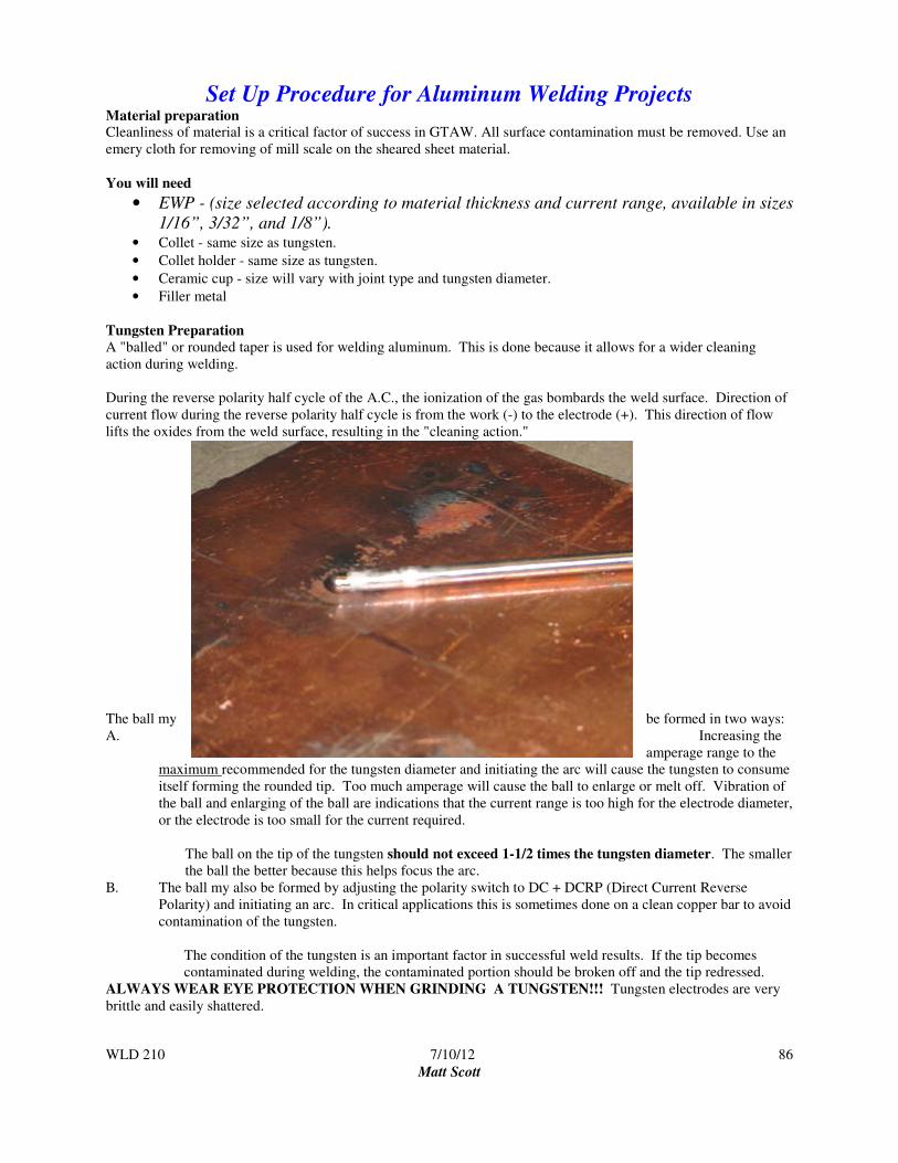
WLD 210 7/10/12
Matt Scott
86
Set Up Procedure for Aluminum Welding Projects Material preparation Cleanliness of material is a critical factor of success in GTAW. All surface contamination must be removed. Use an
emery cloth for removing of mill scale on the sheared sheet material.
You will need
• EWP - (size selected according to material thickness and current range, available in sizes
1/16”, 3/32”, and 1/8”). • Collet - same size as tungsten.
• Collet holder - same size as tungsten.
• Ceramic cup - size will vary with joint type and tungsten diameter.
• Filler metal
Tungsten Preparation
A "balled" or rounded taper is used for welding aluminum. This is done because it allows for a wider cleaning
action during welding.
During the reverse polarity half cycle of the A.C., the ionization of the gas bombards the weld surface. Direction of
current flow during the reverse polarity half cycle is from the work (-) to the electrode (+). This direction of flow
lifts the oxides from the weld surface, resulting in the "cleaning action."
The ball my be formed in two ways:
A. Increasing the
amperage range to the
maximum recommended for the tungsten diameter and initiating the arc will cause the tungsten to consume
itself forming the rounded tip. Too much amperage will cause the ball to enlarge or melt off. Vibration of
the ball and enlarging of the ball are indications that the current range is too high for the electrode diameter,
or the electrode is too small for the current required.
The ball on the tip of the tungsten should not exceed 1-1/2 times the tungsten diameter. The smaller
the ball the better because this helps focus the arc.
B. The ball my also be formed by adjusting the polarity switch to DC + DCRP (Direct Current Reverse
Polarity) and initiating an arc. In critical applications this is sometimes done on a clean copper bar to avoid
contamination of the tungsten.
The condition of the tungsten is an important factor in successful weld results. If the tip becomes
contaminated during welding, the contaminated portion should be broken off and the tip redressed.
ALWAYS WEAR EYE PROTECTION WHEN GRINDING A TUNGSTEN!!! Tungsten electrodes are very
brittle and easily shattered.
WLD 210 7/10/12
Matt Scott
87
• Ball Tungsten Grind to a point using the grinder designated for tungsten only in GTAW
area. Do not grind the end with the red band on it.
Torch Assembly
• Loosen cap of torch until "0" ring is visible.
• Insert tungsten in collet and collet into collet holder. Screw this assembly into
front of torch, finger tight only.
• Screw on ceramic cup and adjust tungsten stick out (the distance the tungsten
extends beyond the cup). Tungsten stick out will vary with joint type. Stick out should be long enough to
insure proper arc length but should not exceed your cup diameter to insure proper shielding
• Tighten torch cap to secure tungsten position finger tight only.
Machine Adjustment • Polarity switch should be set on alternating current with high frequency on continuously (ACHF).
• Current range is adjusted by setting coarse adjustment and fine adjustment
according to electrode diameter, material thickness and weld joint requirement.
• Remote/Standard switch - set on remote.
• Post flow timer adjusted to sufficiently shield tungsten and weld crater.
• High frequency switch should be in continuous or “on” position.
• Turn power switch on.
• Turn on gas and water supply at service lines.
• Depress foot control to initiate gas flow and water (if water cooled torch).
• Make sure torch is not in contact with grounded surface or it will arc. Set gas flow rate at 10 - 15 c.f.h. by
adjusting knob on flow meter. Check water return line to see that water is flowing.
• Test machine adjustments on a piece of scrap.

Matt Scott 7/10/12 88
Craftsmanship for Welding Projects
Your instructor will help you in evaluating your welding projects by the following target standards. Read carefully and
apply these target standards to your project before asking for the instructor's approval.
Steps in completing welding projects: 1. Thoroughly read each drawing.
2. Utilize scrap material to adjust machine and practice welds.
3. Assemble the welding projects per drawing specifications.
4. Review the Welding Procedure portion of the prints.
5. Complete welding project. Practice as needed.
6. Complete the student assessment piece on the project sheet.
7. Submit project to the instructor for the final grading.
Factors for grading welding projects are based on the following criteria Metal Preparation - Thoroughly clean metal
Project Layout - Correct joint assembly
Target Weld Quality - See chart below
Weld Quality per AWS D1.1
VT Criteria Cover Pass
Weld Size See specification on drawing
Undercut 1/32” deep
Weld Contour Smooth Transition
Penetration N/A
Cracks None Allowed
Arc Strikes None Allowed
Fusion Complete Fusion Required
Porosity None Allowed
Overlap None Allowed
Example of a High Quality Weld

WLD 210 7/10/12 89
Matt Scott
GTAW Flat Position Corner Joint (Autogenous/Fuse Weld) Project #11
Objectives of this welding exercise are: • To practice set up and adjustment of the equipment.
• To develop consistency in control of travel speed and arc length.
• Your goal is to fuse the edge surfaces resulting in a smooth rounded contour on all sides of the joint. Note that
when “fuse” welding no filler material is added.
Cause and effect factors
Amperage Too high = undercutting, or melting holes through the work
Too low = lack of fusion on the edges of the joint
Travel Speed Too slow = excessive heat, irregular shape, burning holes
Too fast = weld does not wrap the edges of the plates leaving them sharp and jagged.
Arc length Too short = touching the tungsten to the work, contaminating the tungsten and the work.
Too long = undercutting, and can result in loss of gas coverage creating porosity.
VT Criteria Student Assessment Instructor Assessment
Weld Size
Undercut
Weld Contour
Penetration
Cracks
Arc Strikes
Fusion
Porosity
Overlap
Completed GRADE

WLD 210 7/10/12 90
Matt Scott

WLD 210 7/10/12 91
Matt Scott
GTAW Horizontal T Joint Project #12
Objectives of this welding exercise are:
• To practice set up and adjust of the equipment for a different application.
• To develop consistency in your ability to control travel speed and arc length.
• To develop the ability to add filler material to the weld pool.
VT Criteria Student Assessment Instructor Assessment
Weld Size
Undercut
Weld Contour
Penetration
Cracks
Arc Strikes
Fusion
Porosity
Overlap
Completed GRADE

WLD 210 7/10/12 92
Matt Scott

WLD 210 7/10/12 93
Matt Scott
GTAW Horizontal Lap Joint Project #13
Objectives of this welding exercise are:
• To practice set up and adjust of the equipment for a different application.
• To develop consistency in your ability to control travel speed and arc length.
• To develop the ability to add filler material to the weld pool.
VT Criteria Student Assessment Instructor Assessment
Weld Size
Undercut
Weld Contour
Penetration
Cracks
Arc Strikes
Fusion
Porosity
Overlap
Completed GRADE

WLD 210 7/10/12 94
Matt Scott
WLD 210 7/10/12 95
Matt Scott
Final Exam
This portion of the final exam is a closed book test. Consult with your instructor to determine items that you may
need to review. Once you determine that you are ready for the exam, see your instructor. Once completed, return
the exam to your instructor.
Study Guide
FAA objectives: Know the method of cleaning magnesium in preparation for welding
Know the main function of a flux while welding magnesium
Know the types of gases to use when gas-welding magnesium
Know the use of butt joints when gas-welding magnesium
Know the use of silver soldering as a method of bonding metals
Know the preparation of stainless steel for soldering
Know the methods of cleaning material after soldering
Know the types of tubing splices
Know the proper welding sequence to use when welding fuselage tubes
Know the characteristics of a welded tubing joint
Know the protection of the interior of tubular steel that is to be closed by welding
Know the methods used to control distortion of steel tube structures during welding repairs
Know the preparation of tube ends for welding
Be able to use cleaning operations to prepare sheet steel for welding
Be able to adjust oxyacetylene welding torch to produce the type flame needed to weld a specified material
Be able to select and use filler rod
Know the effect of excessive heat on metal
Be able to operate a portable welding set
Be able to select the correct size welding torch tip
Know the precautions regarding welding over a previously brazed or soldered joint
Be able to sweat-solder a lap joint
Be able to normalize a steel part after welding
Be able to identify steel parts considered to be repairable by welding
Know the preheating required prior to welding
Know the filler rod to use when welding aluminum with oxyacetylene
Know the flux to use when welding aluminum
Know the purpose and effect of using inert gas to shield the arc in certain types of welding

WLD 210 7/10/12 96
Matt Scott
WLD 210 Answer Sheet
Name: _____________________________________ Date: ___________________
1.
19.
2.
20.
3.
21.
4.
22.
5.
23.
6.
24.
7.
25.
8.
26.
9.
27.
10.
28.
11.
29.
12.
30.
13.
31.
14.
32.
15.
33.
16.
34.
17.
35.
18.
36.

WLD 210 7/10/12 97
Matt Scott
Final Grades - WLD 210 Name: _________________ Instructor: ___________________ Date: __________________
Welding Projects = 40%
Out of Out of Out of
Out of Out of Out of
Out of Out of Out of
Out of Out of Out of
Out of Out of Out of
Out of Out of Out of
A Total Project pts. ________ / Total pts. Possible _______ X 40 = _______ %
Written Work = 20%
Out of Out of Out of
Out of Out of Out of
Out of Out of Out of
B Total Project pts. ________ / Total pts. Possible _______ X 20 = _______ %
Safety = 15% Each day of attendance is worth 3 points earned. Any safety violation will result in 0 points for the
day.
Out of Out of Out of Out of Out of Out of
Out of Out of Out of Out of Out of Out of
Out of Out of Out of Out of Out of Out of
C Total pts. earned ________ / Total pts. Possible _______ X 15 = _______ %
Employability Skills = 15% The following attributes will be assessed - attendance, attitude, time management,
team work, interpersonal skills, etc.. Daily points (there are no excused absences, hence no points earned for days
missed ) 3 pts = present and working for the entire shift; 2 pts = late; 1 pt = late and left early; 0 pts = no show.
Out of Out of Out of Out of Out of Out of
Out of Out of Out of Out of Out of Out of
Out of Out of Out of Out of Out of Out of
D Total pts. earned ________ / Total pts. Possible _______ X 15 = _______ %
Final Exam 10%
Written Exam Out of
Practical Exam Out of
E Total Project pts. ________ / Total pts. Possible _______ X 10 = _______ %
Add Lines A + B + C + D + E. This will give you your Final Grade TOTAL % _________
FINAL GRADE _________
Top Related