


Languages
Pages
Legal

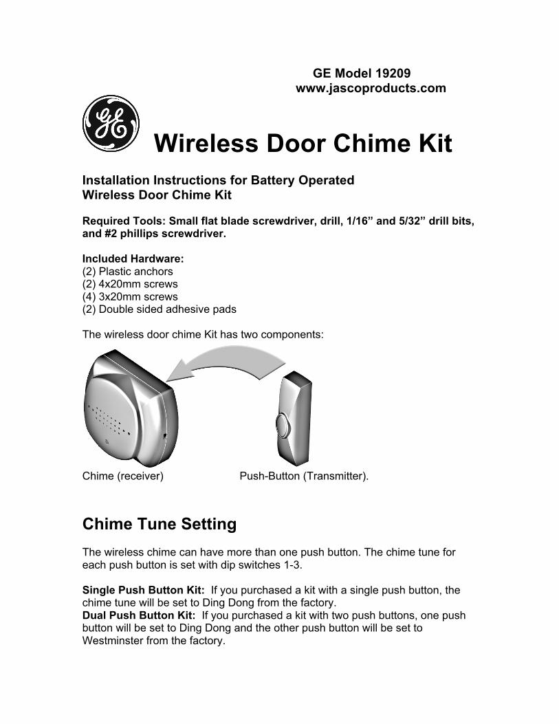
GE Model 19209 www.jascoproducts.com
Wireless Door Chime Kit Installation Instructions for Battery Operated Wireless Door Chime Kit Required Tools: Small flat blade screwdriver, drill, 1/16” and 5/32” drill bits, and #2 phillips screwdriver. Included Hardware: (2) Plastic anchors (2) 4x20mm screws (4) 3x20mm screws (2) Double sided adhesive pads The wireless door chime Kit has two components:
Chime (receiver) Push-Button (Transmitter). Chime Tune Setting The wireless chime can have more than one push button. The chime tune for each push button is set with dip switches 1-3. Single Push Button Kit: If you purchased a kit with a single push button, the chime tune will be set to Ding Dong from the factory. Dual Push Button Kit: If you purchased a kit with two push buttons, one push button will be set to Ding Dong and the other push button will be set to Westminster from the factory.
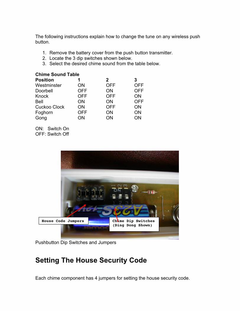
The following instructions explain how to change the tune on any wireless push button.
1. Remove the battery cover from the push button transmitter. 2. Locate the 3 dip switches shown below. 3. Select the desired chime sound from the table below.
Chime Sound Table Position 1 2 3 Westminster ON OFF OFF Doorbell OFF ON OFF Knock OFF OFF ON Bell ON ON OFF Cuckoo Clock ON OFF ON Foghorn OFF ON ON Gong ON ON ON ON: Switch On OFF: Switch Off
Pushbutton Dip Switches and Jumpers Setting The House Security Code Each chime component has 4 jumpers for setting the house security code.
Chime Dip Switches (Ding Dong Shown)
House Code Jumpers
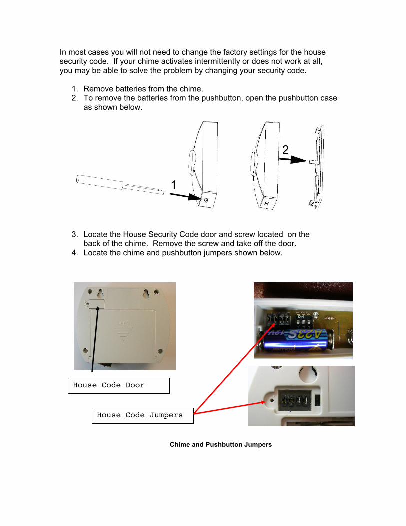
In most cases you will not need to change the factory settings for the house security code. If your chime activates intermittently or does not work at all, you may be able to solve the problem by changing your security code.
1. Remove batteries from the chime. 2. To remove the batteries from the pushbutton, open the pushbutton case
as shown below.
3. Locate the House Security Code door and screw located on the
back of the chime. Remove the screw and take off the door. 4. Locate the chime and pushbutton jumpers shown below.
Chime and Pushbutton Jumpers
House Code Jumpers
House Code Door
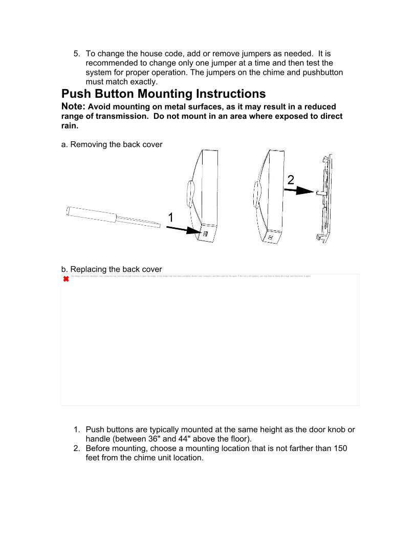
5. To change the house code, add or remove jumpers as needed. It is recommended to change only one jumper at a time and then test the system for proper operation. The jumpers on the chime and pushbutton must match exactly.
Push Button Mounting Instructions Note: Avoid mounting on metal surfaces, as it may result in a reduced range of transmission. Do not mount in an area where exposed to direct rain. a. Removing the back cover
b. Replacing the back cover
1. Push buttons are typically mounted at the same height as the door knob or handle (between 36" and 44" above the floor).
2. Before mounting, choose a mounting location that is not farther than 150 feet from the chime unit location.
The image cannot be displayed. Your computer may not have enough memory to open the image, or the image may have been corrupted. Restart your computer, and then open the file again. If the red x still appears, you may have to delete the image and then insert it again.
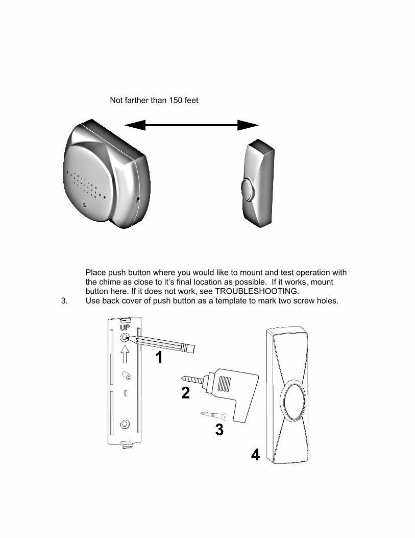
Not farther than 150 feet
Place push button where you would like to mount and test operation with the chime as close to it’s final location as possible. If it works, mount button here. If it does not work, see TROUBLESHOOTING.
3. Use back cover of push button as a template to mark two screw holes.
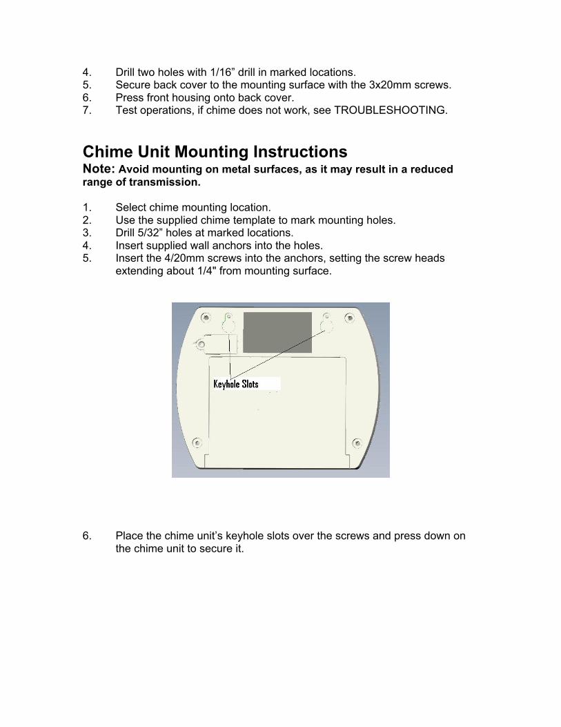
4. Drill two holes with 1/16” drill in marked locations. 5. Secure back cover to the mounting surface with the 3x20mm screws. 6. Press front housing onto back cover. 7. Test operations, if chime does not work, see TROUBLESHOOTING. Chime Unit Mounting Instructions Note: Avoid mounting on metal surfaces, as it may result in a reduced range of transmission. 1. Select chime mounting location. 2. Use the supplied chime template to mark mounting holes. 3. Drill 5/32” holes at marked locations. 4. Insert supplied wall anchors into the holes. 5. Insert the 4/20mm screws into the anchors, setting the screw heads
extending about 1/4" from mounting surface.
6. Place the chime unit’s keyhole slots over the screws and press down on
the chime unit to secure it.
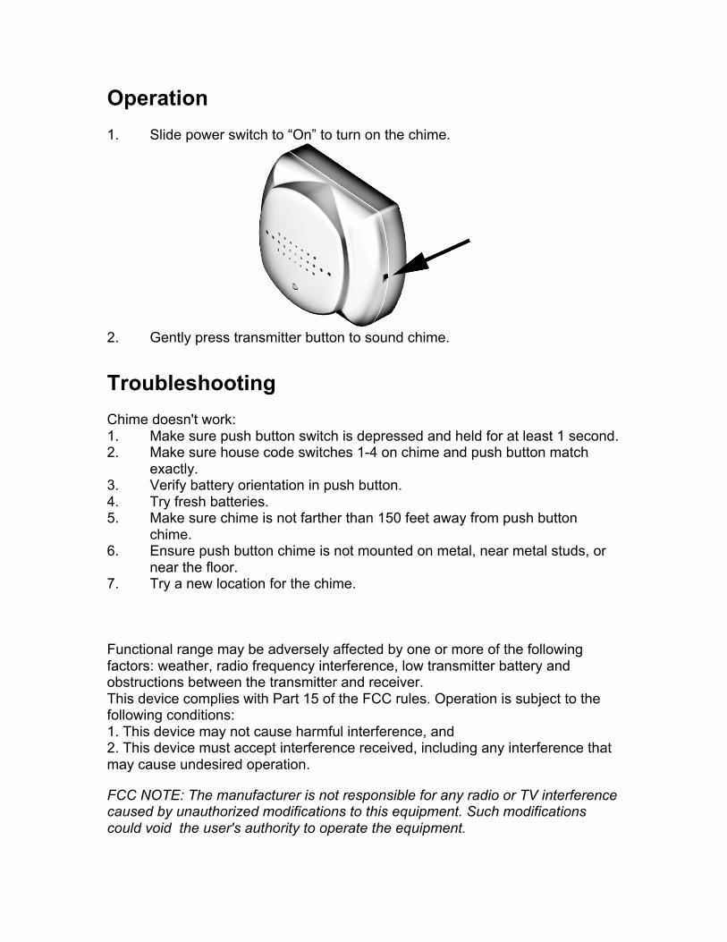
Operation 1. Slide power switch to “On” to turn on the chime.
2. Gently press transmitter button to sound chime. Troubleshooting Chime doesn't work: 1. Make sure push button switch is depressed and held for at least 1 second. 2. Make sure house code switches 1-4 on chime and push button match
exactly. 3. Verify battery orientation in push button. 4. Try fresh batteries. 5. Make sure chime is not farther than 150 feet away from push button
chime. 6. Ensure push button chime is not mounted on metal, near metal studs, or
near the floor. 7. Try a new location for the chime. Functional range may be adversely affected by one or more of the following factors: weather, radio frequency interference, low transmitter battery and obstructions between the transmitter and receiver. This device complies with Part 15 of the FCC rules. Operation is subject to the following conditions: 1. This device may not cause harmful interference, and 2. This device must accept interference received, including any interference that may cause undesired operation. FCC NOTE: The manufacturer is not responsible for any radio or TV interference caused by unauthorized modifications to this equipment. Such modifications could void the user's authority to operate the equipment.
NOTE: This equipment has been tested and found to comply with the limits for a Class B digital device, pursuant to Part 15 of the FCC Rules. These limits are designed to provide reasonable protection against harmful interference in a residential installation. This equipment generates, uses and can radiate radio frequency energy and, if not installed and used in accordance with the instructions may cause harmful interference to radio communications. However, there is no guarantee that interference will not occur in a particular installation. If this equipment does cause harmful interference to radio or television reception, which can be determined by turning the equipment off and on, the user is encouraged to try to correct the interference by one or more of the following measures: -- Reorient or relocate the receiving antenna. -- Increase the separation between the equipment and receiver. -- Connect the equipment into an outlet on a circuit different from that to which the receiver is connected. Consult the dealer or an experienced radio/TV technician for help.
For technical support contact Jasco Products Company at 1-800-654-8483 Select option 4 if prompted or www.jascoproducts.com Made in China Hecho en China
is a trademark of General Electric Company and is used under license to Jasco Products Company LLC, 10 E. Memorial Road, Oklahoma City, OK 73114. www.jascoproducts.com Rev. 10-11 19209
Top Related