


Languages
Pages
Legal

321070
Reducing Interrupt Latency Through the Use of Message Signaled Interrupts
January 2009
White Paper James Coleman
Performance Architect
Intel Corporation

Reducing Interrupt Latency Through the Use of Message Signaled Interrupts
2 321070
Executive Summary Embedded systems have traditionally been much more sensitive to both
the interrupt latency and Central Processing Unit (CPU) overhead involved
in servicing interrupts as compared to conventional Personal Computers
(PC). Message Signaled Interrupts (MSI) represent the third generation of
interrupt delivery methods for IO (Input/Output) devices, providing many
benefits, including a significant reduction in interrupt latency. Intel®
architecture, consisting of a CPU, memory controller, and an IO
controller, can provide the embedded developer with a competitive
platform for embedded designs. Linux, a mature yet flexible open source
operating system, has been extensively optimized for Intel® architecture,
providing a robust interrupt framework supporting MSI.
Message Signaled Interrupts greatly reduce the interrupt latency and
the CPU overhead involved in servicing interrupts, boosting general
system performance as well as IO responsiveness, both critical to
embedded applications.
The first generation of interrupts (XT-PIC) required a cumbersome
delivery and servicing mechanism that only supported 15 interrupts. The
second generation (IO-APIC) somewhat simplified the delivery and
servicing mechanism introduced with XT-PIC but only increased the
number of supported interrupts to 24. The third generation, MSI, greatly
simplifies the delivery and servicing of interrupts, increasing the number
of available interrupts to 224.
The methodology used by Intel’s embedded group to measure the
interrupt latency on IA platforms consists of using a Peripheral
Component Interconnect Express* (PCIe*) exerciser to generate the
Reducing Interrupt Latency Through the Use of Message Signaled Interrupts
321070 3
interrupt, creating a custom Linux kernel module to act as a device driver
providing an Interrupt Service Routine (ISR), and measuring (with a PCIe
analyzer) the time from when the interrupt is sent to when the CPU runs
the ISR.
Results collected using this method across two classes of Intel platforms
(Workstation and System on Chip (SOC)) show a 3x reduction in interrupt
latency when using MSI as compared to IO-APIC and over a 5x reduction
when compared to XT-PIC. MSI greatly reduces interrupt latency and the
CPU overhead involved in servicing interrupts.
Reducing Interrupt Latency Through the Use of Message Signaled Interrupts
4 321070
Contents Executive Summary ..............................................................................2
Contents..............................................................................................4
Business Challenge................................................................................5
Solution...............................................................................................5
Introduction to Interrupts on Intel® Architecture .......................................5
Intel® Architecture Overview ..................................................................6 CPU .............................................................................7 MCH .............................................................................7 IO Controller Hub ..............................................................7 FSB .............................................................................7 Overview of Interrupts on Intel® Architecture Under Linux*.....7
Overview of Interrupt Delivery Methods ...................................................8 Legacy XT-PIC Interrupts ...................................................8 IO-APIC Interrupts ..........................................................10 Message Signaled Interrupts .............................................11
PCIe* Interrupt Latency Methodology ....................................................11 Interrupt Generation........................................................12 Event Observation ...........................................................15
Results ..............................................................................................18 Workstation Class Platform ...............................................18 System-on-a-Chip Platform...............................................19
Conclusion .........................................................................................20

Reducing Interrupt Latency through the use of Message Signaled Interrupts
321070 5
Business Challenge Embedded systems traditionally have been much more sensitive to interrupt latency than conventional PCs. The perception that Intel® architecture has a cumbersome interrupt handling scheme has caused many embedded developers to avoid developing embedded systems on Intel® architecture. With the advent of MSI, introduced as an optional feature in version 2.2 of the Peripheral Component Interconnect (PCI) specification and as a mandatory feature of the PCIe* specification, the interrupt delivery and servicing scheme is greatly simplified.
Solution The introduction of the MSI delivery and servicing method removed the two big limitations associated with the PCI IO architecture, namely, the limited number of interrupts and the unnecessarily high interrupt latencies. Embedded developers already using Intel® architecture can realize a significant reduction in interrupt latency by transitioning to MSI. Those not yet realizing the benefits of the embedded Intel® architecture ecosystem can move to Intel® architecture, knowing that Intel® architecture provides extremely competitive interrupt latency.
Adoption of the MSI software model for interrupt delivery and servicing was delayed because it required changes to operating systems to support MSI. Even the mainstream operating systems, Windows* and Linux*, had a delayed implementation, with Linux incorporating it four years after the specification and Windows another four years behind Linux. With support now widespread in traditional operating systems, the critical mass now exists to support a healthy ecosystem of hardware devices and accompanying drivers that utilize MSI.
Introduction to Interrupts on Intel® Architecture
This paper presents a comparison of interrupt latencies for an Intel® architecture system using the original Intel® 8259 Programmable Interrupt Controller (PIC) method, the legacy IO-Advanced Programmable Interrupt Controller (IO-APIC) method, as well as the MSI delivery and servicing method. In addition to the comparison of interrupt latencies, this paper

Reducing Interrupt Latency through the use of Message Signaled Interrupts
6 321070
provides example code and benchmarks for several classes of Intel® platforms.
Intel® Architecture Overview This section provides a brief overview of the Intel® architecture. For more information on this topic, refer to Introduction to Intel Architecture – The Basics.
Intel® architecture can be broken down into two main categories, components (silicon) and interfaces connecting the silicon. The components of interest are Central Processor Unit (CPU), Memory Controller Hub (MCH) and IO Controller Hub. The interfaces of interest are the Front Side Bus (FSB), memory interface, PCI Express* (PCIe*), and Direct Media Interface (DMI). Figure 1 below shows a generic Intel® architecture block diagram.
Figure 1. Intel® Architecture Block Diagram
FSB
/QPI
DM
I
Mem
ory
Mem
ory

Reducing Interrupt Latency through the use of Message Signaled Interrupts
321070 7
CPU
At a high level, the CPU is the brain of the system where all execution occurs, and all other components of Intel® architecture support the CPU. The CPU consists of the execution units and pipelines, caches, and the FSB unit. An important concept to understand for this paper relates to cacheable memory. CPU caches are filled one full cache line at a time. This means that if one byte is required by an execution unit, the CPU will fetch an entire cache line (64 bytes) into the CPU cache. All accesses to cacheable memory are done in cache line sized quantities. This cacheable memory behavior is consistent across all interfaces and components.
MCH
If the CPU is the brain, then the MCH is the heart of Intel® architecture. The MCH routes all requests and data to the appropriate interface. It is the connecting piece between the CPU, memory, and IO. It contains the memory controller, FSB unit, PCI Express* ports, DMI port, coherency engine, and arbitration.
IO Controller Hub
The IO Controller Hub provides extensive IO support for peripherals: USB, audio, SATA, SuperIO, LAN as well as the logic for ACPI power management, fan speed control, reset timing, and interrupt control and routing. The IO Controller Hub connects to the MCH via the DMI interface, a proprietary “PCI Express*-like” interface.
FSB
The FSB is a parallel bus that enables communication between the CPU and MCH. The FSB consists of 32 to 40 address bits and strobes, 64 data bits and strobes, four request bits and side band signals. Data is quad-pumped, allowing data transfer of 32 bytes per bus clock. Transactions are broken into phases, such as request, response, snoop, and data.
Overview of Interrupts on Intel® Architecture Under Linux*
Linux* has been designed to be a responsive operating system with respect to interrupt servicing. As a result, an interrupt service routine (ISR) and tasklet approach has been taken to accommodate even the most CPU-intensive computation of data requested by an interrupt while ensuring that all interrupts are serviced quickly. This approach allows the most critical actions needed by hardware to be taken in a timely manner even when a system is heavily loaded with interrupt-related processing.

Reducing Interrupt Latency through the use of Message Signaled Interrupts
8 321070
Interrupt Service Routine, the First Responder
With the Linux* interrupt architecture, the ISR for a device performs only the bare minimum to keep the device functioning, leaving all other data processing to the tasklet. Once the device has been serviced, the ISR can schedule a tasklet to run. This tasklet processes any data that has arrived as a result of the interrupt. Not processing data in the ISR means that interrupts are disabled only as long as absolutely necessary in order to keep all attached devices functioning properly. This ensures that all devices will see the operating system (OS) as very responsive even if one device, such as a network controller, is heavily loading the system with work.
Scheduled Tasklet, the Workhorse
An ISR schedules a tasklet when an interrupt requires data processing beyond the minimum needed to keep the device functioning. Tasklets are run by the OS after all pending interrupts have been serviced. Newly arriving interrupts will preempt currently running tasklets, ensuring system responsiveness. Tasklets are scheduled on a higher priority than user-level jobs, ensuring that the data is processed in a timely manner.
Overview of Interrupt Delivery Methods
This section provides an overview of the three generations of interrupt delivery and servicing on Intel architecture: XT-PIC for legacy uni-processor (UP) systems, IO-APIC for modern UP and multi-processor (MP) systems, and MSI.
Legacy XT-PIC Interrupts
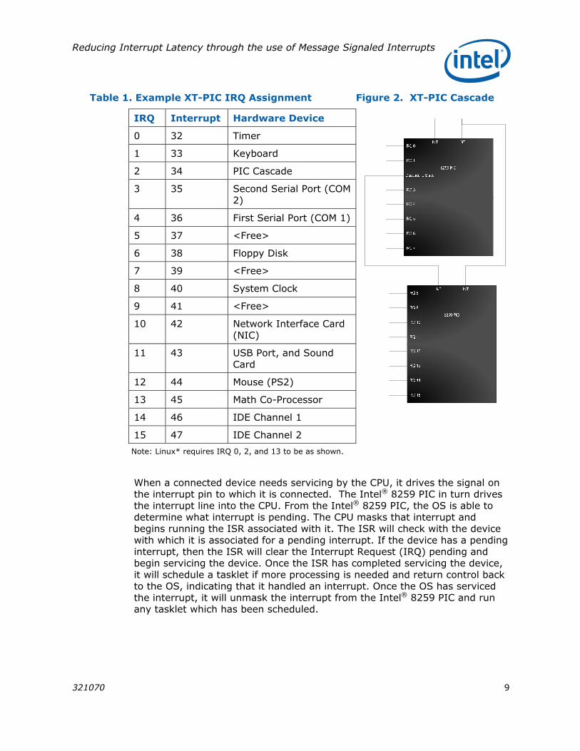
Legacy XT-PIC interrupts comprise the oldest form of interrupt delivery supported by a PCI device. XT-PIC interrupts use a pair of Intel® 8259 programmable interrupt controllers (PIC). Each Intel® 8259 PIC supports only eight interrupts. By daisy chaining two 8259 PICs, a system could have 16 interrupts, 0 – 15. Table 1 shows an example allocation of interrupts, and Figure 2 shows how the PICs would be connected.
Reducing Interrupt Latency through the use of Message Signaled Interrupts
321070 9
Table 1. Example XT-PIC IRQ Assignment Figure 2. XT-PIC Cascade
IRQ Interrupt Hardware Device
0 32 Timer
1 33 Keyboard
2 34 PIC Cascade
3 35 Second Serial Port (COM 2)
4 36 First Serial Port (COM 1)
5 37 <Free>
6 38 Floppy Disk
7 39 <Free>
8 40 System Clock
9 41 <Free>
10 42 Network Interface Card (NIC)
11 43 USB Port, and Sound Card
12 44 Mouse (PS2)
13 45 Math Co-Processor
14 46 IDE Channel 1
15 47 IDE Channel 2
Note: Linux* requires IRQ 0, 2, and 13 to be as shown.
When a connected device needs servicing by the CPU, it drives the signal on the interrupt pin to which it is connected. The Intel® 8259 PIC in turn drives the interrupt line into the CPU. From the Intel® 8259 PIC, the OS is able to determine what interrupt is pending. The CPU masks that interrupt and begins running the ISR associated with it. The ISR will check with the device with which it is associated for a pending interrupt. If the device has a pending interrupt, then the ISR will clear the Interrupt Request (IRQ) pending and begin servicing the device. Once the ISR has completed servicing the device, it will schedule a tasklet if more processing is needed and return control back to the OS, indicating that it handled an interrupt. Once the OS has serviced the interrupt, it will unmask the interrupt from the Intel® 8259 PIC and run any tasklet which has been scheduled.

Reducing Interrupt Latency through the use of Message Signaled Interrupts
10 321070
XT-PIC Limitations
The Intel® 8259 PIC presents several limitations to interrupt servicing:
• A limited number of interrupt lines necessitates the sharing of interrupts. Shared interrupts require the OS to run multiple ISRs and query multiple IO devices to determine who actually generated the interrupt.
• Interrupt priority is fixed based on IRQ number.
• XT-PIC architecture does not support multiple CPUs.
• Slow IO reads and writes to interact with the Intel® 8259 hardware.
• The CPU can begin servicing the interrupt before the data is written to memory.
o The data written to memory by the device may be queued up in write buffers on their way to system memory.
o As soon as the interrupt (INT) signal is driven to the CPU, the OS begins processing the interrupt, forcing software to issue a write to memory to flush out any pending writes prior to reading the data from memory.
IO-APIC Interrupts
Intel developed the multiprocessor specification in 1994, which introduced the concept of a Local-APIC (Advanced PIC) in the CPU and IO-APICs connected to devices. This architecture addressed many of the limitations of the older XT-PIC architecture. The most apparent is the support for multiple CPUs. Additionally, each IO-APIC (82093) has 24 interrupt lines and allows the priority of each interrupt to be set independently. The programming model of the IO-APIC is greatly simplified. The IO-APIC writes an interrupt vector to the Local-APIC, and, as a result, the OS does not have to interact with the IO-APIC until it sends the end of interrupt notification.
The IO-APCI provides backwards compatibility with the older XT-PIC model. As a result, the lower 16 interrupts are usually dedicated to their assignments under the XT-PIC model. This assignment of interrupts provides only eight additional interrupts, which forces sharing. The following is the sequence for IO-APIC delivery and servicing:
• A device needing servicing from the CPU drives the interrupt line into the IO-APIC associated with it.
• The IO-APIC writes the interrupt vector associated with its driven interrupt line into the Local APIC of the CPU.
• The interrupted CPU begins running the ISRs associated with the interrupt vector it received.

Reducing Interrupt Latency through the use of Message Signaled Interrupts
321070 11
o Each ISR for a shared interrupt is run to find the device needing service.
o Each device has its IRQ pending bit checked, and the requesting device has its bit cleared.
Message Signaled Interrupts
MSI was introduced in revision 2.2 of the PCI spec in 1999 as an optional component. However, with the introduction of the PCIe specification in 2004, implementation of MSI became mandatory from a hardware standpoint. Unfortunately, software support in mainstream operating systems was slow in coming, forcing many MSI-capable PCIe* devices to operate in legacy mode. The MSI model eliminates the devices’ need to use the IO-APIC, allowing every device to write directly to the CPU’s Local-APIC. The MSI model supports 224 interrupts, and, with this high number of interrupts, IRQ sharing is no longer allowed. The following is the sequence for MSI delivery and servicing:
• A device needing servicing from the CPU generates an MSI, writing the interrupt vector directly into the Local-APIC of the CPU servicing it.
• The interrupted CPU begins running the ISR associated with the interrupt vector it received. The device is serviced without any need to check and clear an IRQ pending bit
PCIe* Interrupt Latency Methodology
As interrupt latency is important for embedded applications, Intel has made several architectural enhancements to better accommodate efficient interrupt handling. Additionally, Intel has tracked the changes in interrupt performance from generation to generation. The interrupt performance of each platform generation is based on the interrupt latency. The interrupt latency is defined as the elapsed time from when a device requests servicing from the CPU (the generation of the interrupt) to when the CPU begins servicing the device (running the ISR). Intel has developed a methodology for measuring this latency, which is presented here. This methodology applies to the Linux* family of operating systems.
This section describes the methodology used for the setup, execution, and collection of data for the measurement of interrupt latency on XT-PIC, IO-APIC, and MSI systems with both Symmetric Multi-processor (SMP) and UP Linux 2.6 kernels. The latency analysis involves two separate observation points: first, a PCIe analyzer, and, secondly, an FSB analyzer.

Reducing Interrupt Latency through the use of Message Signaled Interrupts
12 321070
Interrupt Generation
The interrupt latency measurement requires two events: the interrupt itself and some indication of the start of servicing by the ISR. As a result of this requirement, the methodology provides for both the generation of interrupts as well as the generation of an ISR to service the interrupts. PCIe* exerciser cards are used to generate the interrupts. Any third party PCIe* exerciser capable of creating an “Assert X” or MSI packet is sufficient. A custom device driver for Linux is needed to request an interrupt assignment from the OS and to register an ISR for the granted interrupt with the OS. An overview of such a device driver is provided in subsequent sections.
The following sections outline the methodology utilized to configure the operating system to use the appropriate interrupt architecture, to configure an exerciser for interrupt generation, and to configure a device driver to request an interrupt and to supply an ISR.
XT-PIC OS Configuration
XT-PIC interrupt delivery under Linux* is only supported for UP kernels. A 2.6 version of the kernel can be recompiled as UP with XT-PIC support by making the following changes. First, append _XT-PIC to the EXTRAVERSION of the Makefile found in the Linux source directory. Once the Makefile has been updated, the kernel needs to be configured as UP. This can be accomplished by disabling Symmetric mulit-processor support under the Processor Types and features menu of the Linux Kernel Configuration Menu, which is accessed via make menuconfig. Finally, the Local-APIC must be disabled by deselecting Local-APIC support on uniprocessors from the same menu. With only these options changed from the default settings, the kernel configuration can be saved and the kernel recompiled. Booting into the newly compiled kernel will provide a UP OS that only supports XT-PIC interrupts.
IO-APIC OS Configuration
IO-APIC interrupt delivery under Linux is supported for both UP and SMP kernels. A 2.6 version of the kernel can be recompiled as either UP or SMP with IO-APIC support by making the following changes. First, append either <SMP/UP> as well as _IO-APIC to the EXTRAVERSION of the Makefile found in the Linux source directory. Once the Makefile has been updated, the kernel should be configured as either UP or SMP, depending on the configuration desired. This can be accomplished by either enabling or disabling Symmetric mulit-processor support under the Processor Types and features menu of the Linux Kernel Configuration Menu, which is accessed via make menuconfig. In the case of a UP kernel, the Local-APIC must be enabled by selecting Local APIC support on uniprocessors from the same menu. Additionally, for both UP and SMP kernel configurations, MSI support should be disabled under the Bus Options submenu of the Processor types and features menu. With only these options changed from the default settings, the kernel configuration can be

Reducing Interrupt Latency through the use of Message Signaled Interrupts
321070 13
saved and the kernel recompiled. Booting into the newly compiled kernel will provide either a UP or SMP OS that supports IO-APIC interrupts.
MSI OS Configuration
Just like IO-APIC interrupts, MSI interrupt delivery under Linux* is supported for both UP and SMP kernels. A 2.6 version of the kernel can be recompiled as either UP or SMP with MSI support by making the following changes. First, append either <SMP/UP> as well as _MSI to the EXTRAVERSION of the Makefile found in the Linux source directory. Once the Makefile has been updated, the kernel should be configured as either UP or SMP, depending on the configuration desired. This can be accomplished by either enabling or disabling Symmetric mulit-processor support under the Processor Types and features menu of the Linux Kernel Configuration Menu accessed via make menuconfig. In the case of a UP kernel, the Local-APIC must be enabled by selecting Local APIC support on uniprocessors from the same menu. Additionally, for both UP and SMP kernel configurations, MSI support should be enabled under the Bus Options submenu of the Processor types and features menu. With only these options changed from the default settings, the kernel configuration can be saved and the kernel recompiled. Booting into the newly compiled kernel will provide either a UP or SMP OS that supports MSI interrupts.
PCIe* Exerciser Configuration
The PCIe* exerciser must be capable of generating both “Assert X” and MSI packets. The methodology outlined here also requires that the device request a region of Memory Mapped IO (MMIO) to which the ISR and tasklet will write, indicating the entry of each. The details on how to configure a particular PCIe exerciser are beyond the scope of this paper. However, the PCI bus number assigned to the exerciser and the base address mapped to it are both required for the device driver presented in this paper.
Device Driver Kernel Module for the PCIe* Exerciser
A custom kernel module that acts as a device driver for a PCIe* exerciser is presented here. The kernel module provides the ISR for both legacy (XT-PIC and IO-APIC) as well as MSI interrupts. The kernel module generates memory write signatures that can be seen on the FSB as well as the PCIe link. These memory write signatures are generated upon entry of the main ISR as well as the scheduled tasklet. The memory writes themselves are to non-cacheable MMIO locations on the PCIe exerciser. This ensures that only a minimal delay exists between when the CPU enters the ISR or tasklet and issues the write to when it appears on the FSB. The kernel module must be provided with the base address of the MMIO region assigned to the PCIe exerciser so that it can perform the signature writes. For greater functionality, this base address is provided to the device driver through the dev_io_mem command line parameter supplied while inserting the module.
Reducing Interrupt Latency through the use of Message Signaled Interrupts
14 321070
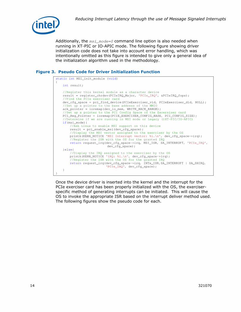
Additionally, the msi_mode=0 command line option is also needed when running in XT-PIC or IO-APIC mode. The following figure showing driver initialization code does not take into account error handling, which was intentionally omitted as this figure is intended to give only a general idea of the initialization algorithm used in the methodology.
Figure 3. Pseudo Code for Driver Initialization Function
static int MSI_init_module (void) { int result; //Register this kernel module as a character device result = register_chrdev(PCIeIRQ_Major, "PCIe_IRQ", &PCIeIRQ_fops); //Find the PCIe exerciser card dev_cfg_space = pci_find_device(PCIeExerciser_vid, PCIeExerciser_did, NULL); //Set up a pointer to the base address of the MMIO ack_pointer = ioremap(dev_io_mem, WRITE_BACK_RANGE); //Set up a pointer to the PCI Config Space of the Excersiser card PCI_Reg_Pointer = ioremap(PCIE_EXERCISER_CONFIG_BASE, PCI_CONFIG_SIZE); //Determine if we are running in MSI mode or Legacy ()XT-PIC/IO-APIC) if(msi_mode){ //Ask Linux to enable MSI support on this device result = pci_enable_msi(dev_cfg_space); //Display the MSI vector assigned to the exerciser by the OS printk(KERN_NOTICE "MSI Interrupt vector: %i.\n", dev_cfg_space->irq); //Register the ISR with the OS for the granted IRQ return request_irq(dev_cfg_space->irq, MSI_ISR, SA_INTERRUPT, "PCIe_IRQ",
dev_cfg_space); }else{ //Display the IRQ assigned to the exerciser by the OS printk(KERN_NOTICE "IRQ: %i.\n", dev_cfg_space->irq); //Register the ISR with the OS for the granted IRQ return request_irq(dev_cfg_space->irq, INTx_ISR,SA_INTERRUPT | SA_SHIRQ,
"PCIe_IRQ", dev_cfg_space); } }
Once the device driver is inserted into the kernel and the interrupt for the PCIe exerciser card has been properly initialized with the OS, the exerciser-specific method of generating interrupts can be initiated. This will cause the OS to invoke the appropriate ISR based on the interrupt deliver method used. The following figures show the pseudo code for each.
Reducing Interrupt Latency through the use of Message Signaled Interrupts
321070 15
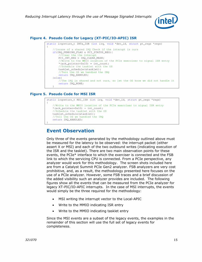
Figure 4. Pseudo Code for Legacy (XT-PIC/IO-APIC) ISR
static irqreturn_t INTx_ISR (int irq, void *dev_id, struct pt_regs *regs) { //Incase of a shared IRQ Check if the interupt is ours if(IRQ_PENDING_FLAG & PCI_STATUS_REG){ //Clear the the interupt PCI_INT_REG = IRQ_CLEAR_MASK; //Write to the MMIO location of the PCIe exerciser to signal ISR entry *(ack_pointer+0x10) = int_count; //Schedule the tasklet with the OS tasklet_schedule(&tasklet); //Tell the OS we handled the IRQ return IRQ_HANDLED; }else{ //The IRQ is shared and not ours, so let the OS know we did not handle it return IRQ_NONE;
}
Figure 5. Pseudo Code for MSI ISR
static irqreturn_t MSI_ISR (int irq, void *dev_id, struct pt_regs *regs) { //Write to the MMIO location of the PCIe exerciser to signal ISR entry *(ack_pointer+0x10) = int_count; //Schedule the tasklet with the OS tasklet_schedule(&tasklet); //Tell the OS we handled the IRQ return IRQ_HANDLED; }
Event Observation
Only three of the events generated by the methodology outlined above must be measured for the latency to be observed: the interrupt packet (either assert X or MSI) and each of the two outbound writes (indicating execution of the ISR and the tasklet). There are two main observation points for these events, the PCIe* interface to which the exerciser is connected and the FSB link to which the servicing CPU is connected. From a PCIe perspective, any analyzer would work for this methodology. The screen shots included here are from a Catalyst Summit PCIe Gen2 analyzer. FSB analyzers are very cost prohibitive, and, as a result, the methodology presented here focuses on the use of a PCIe analyzer. However, some FSB traces and a brief discussion of the added visibility such an analyzer provides are included. The following figures show all the events that can be measured from the PCIe analyzer for legacy XT-PIC/IO-APIC interrupts. In the case of MSI interrupts, the events would simply be the three required for the methodology:
• MSI writing the interrupt vector to the Local-APIC
• Write to the MMIO indicating ISR entry
• Write to the MMIO indicating tasklet entry
Since the MSI events are a subset of the legacy events, the examples in the remainder of this section will use the full set of legacy events for completeness.
Reducing Interrupt Latency through the use of Message Signaled Interrupts
16 321070
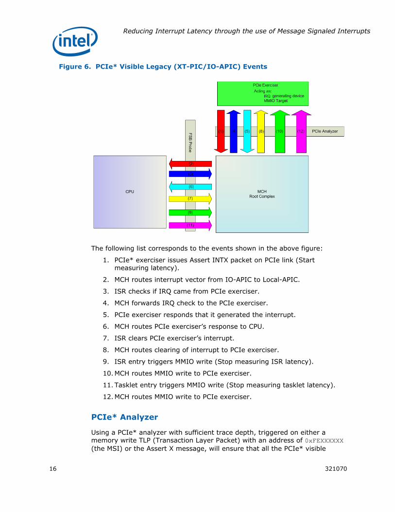
Figure 6. PCIe* Visible Legacy (XT-PIC/IO-APIC) Events
The following list corresponds to the events shown in the above figure:
1. PCIe* exerciser issues Assert INTX packet on PCIe link (Start measuring latency).
2. MCH routes interrupt vector from IO-APIC to Local-APIC.
3. ISR checks if IRQ came from PCIe exerciser.
4. MCH forwards IRQ check to the PCIe exerciser.
5. PCIe exerciser responds that it generated the interrupt.
6. MCH routes PCIe exerciser’s response to CPU.
7. ISR clears PCIe exerciser’s interrupt.
8. MCH routes clearing of interrupt to PCIe exerciser.
9. ISR entry triggers MMIO write (Stop measuring ISR latency).
10. MCH routes MMIO write to PCIe exerciser.
11. Tasklet entry triggers MMIO write (Stop measuring tasklet latency).
12. MCH routes MMIO write to PCIe exerciser.
PCIe* Analyzer
Using a PCIe* analyzer with sufficient trace depth, triggered on either a memory write TLP (Transaction Layer Packet) with an address of 0xFEXXXXXX (the MSI) or the Assert X message, will ensure that all the PCIe* visible
Reducing Interrupt Latency through the use of Message Signaled Interrupts
321070 17
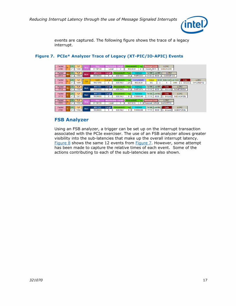
events are captured. The following figure shows the trace of a legacy interrupt.
Figure 7. PCIe* Analyzer Trace of Legacy (XT-PIC/IO-APIC) Events
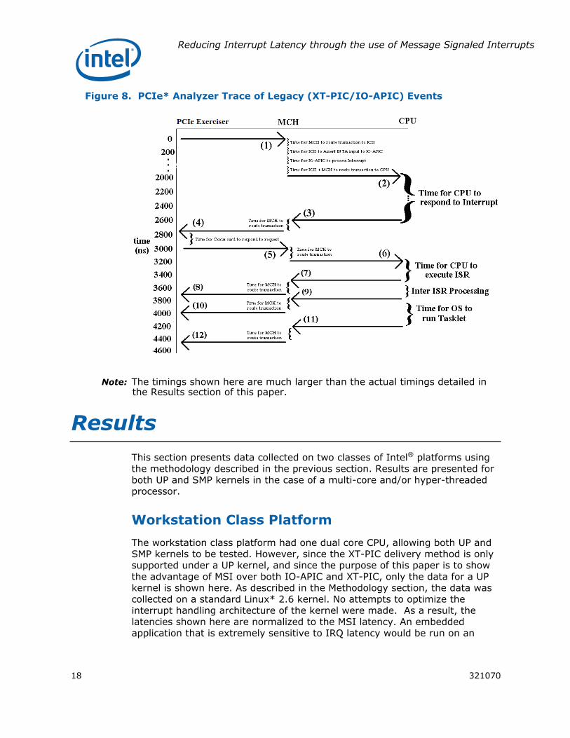
FSB Analyzer
Using an FSB analyzer, a trigger can be set up on the interrupt transaction associated with the PCIe exerciser. The use of an FSB analyzer allows greater visibility into the sub-latencies that make up the overall interrupt latency. Figure 8 shows the same 12 events from Figure 7. However, some attempt has been made to capture the relative times of each event. Some of the actions contributing to each of the sub-latencies are also shown.
Reducing Interrupt Latency through the use of Message Signaled Interrupts
18 321070
Figure 8. PCIe* Analyzer Trace of Legacy (XT-PIC/IO-APIC) Events
Note: The timings shown here are much larger than the actual timings detailed in the Results section of this paper.
Results This section presents data collected on two classes of Intel® platforms using the methodology described in the previous section. Results are presented for both UP and SMP kernels in the case of a multi-core and/or hyper-threaded processor.
Workstation Class Platform
The workstation class platform had one dual core CPU, allowing both UP and SMP kernels to be tested. However, since the XT-PIC delivery method is only supported under a UP kernel, and since the purpose of this paper is to show the advantage of MSI over both IO-APIC and XT-PIC, only the data for a UP kernel is shown here. As described in the Methodology section, the data was collected on a standard Linux* 2.6 kernel. No attempts to optimize the interrupt handling architecture of the kernel were made. As a result, the latencies shown here are normalized to the MSI latency. An embedded application that is extremely sensitive to IRQ latency would be run on an

Reducing Interrupt Latency through the use of Message Signaled Interrupts
321070 19
optimized Real-Time Operating System (RTOS), which would provide the lowest possible IRQ latency for a given platform.
Figure 9. Normalized UP Workstation Results
Workstation PlatformISR Latency Vs. Interrupt Delivery Method
0 1 2 3 4 5 6 7 8
XT-PIC
UP IO-APIC
UP MSI
Inte
rrup
t Del
iver
y M
etho
d
ISR Latency Normalized to MSI(Lower is better)
MSI provides almost a 3x reduction in interrupt latency over IO-APIC, with the advantage over XT-PIC being nearly 7x. The tasklet latencies are proportional to the ISR latencies shown here, with the tasklet latencies being higher than the ISR latencies due to the additional overhead of the OS’ scheduling the tasklet to run. This proportionality in latencies is expected as the system under test was lightly loaded, allowing the tasklets to be scheduled immediately following the execution of the ISR. In a heavily loaded system, the tasklet latencies would be higher (a drawback of the tasklet with ISR framework). However, this is the price that must be paid for the responsiveness enjoyed by all the ISRs under such a framework.
System-on-a-Chip Platform
The SoC platform had a single core CPU, allowing only a UP kernel to be tested. Again, to show the relative advantage of moving to the MSI interrupt delivery method, the data presented here has been normalized.

Reducing Interrupt Latency through the use of Message Signaled Interrupts
20 321070
Figure 10. Normalized UP SoC Results
SOCISR Latency Vs. Interrupt Delivery Method
0 1 2 3 4 5 6 7
XT-PIC
UP IO-APIC
UP MSI
Inte
rrup
t Del
iver
y M
etho
d
ISR Latency Normalized to MSI(Lower is better)
Again, MSI provides about a 3x reduction in interrupt latency over IO-APIC, with the advantage over XT-PIC being just over 6x. The slower CPU frequency relative to the distance of the PIC in an SOC makes the advantage of MSI over XT-PIC only slightly less dramatic.
This survey of two platform classes shows the significant benefit of MSI regardless of the target platform class. The consideration of using MSI should not only be motivated by reducing interrupt latency but by also reducing CPU utilization. The time required for the CPU to respond to the interrupt (interrupt latency) is time essentially wasted by the CPU. For example, a CPU that spends microseconds determining what interrupt needs servicing by polling devices and masking interrupt controllers is unable to carry out other tasks during that time. The CPU, then, is limited in both the number of interrupts it can process per second as well as in the amount of time it can devote to user-level applications. As a result, moving to an MSI delivery and servicing model not only improves IO performance by greatly reducing interrupt latency, but also improves overall system performance by freeing CPU time for other interrupts and user-level applications.
Conclusion MSI provides a significant reduction in interrupt latency over the previous two generations of Intel interrupt architecture. The benefits extend beyond a reduction in interrupt latency to a reduction in CPU utilization by eliminating
Reducing Interrupt Latency through the use of Message Signaled Interrupts
321070 21
the time spent by the CPU determining what interrupt needs servicing (by polling devices and masking interrupt controllers). Embedded developers considering Intel® architecture for a solution or currently developing one should fully adopt the MSI model for interrupt delivery and servicing to ensure not only the best IO performance for their solution, but also the most CPU headroom for user-applications and other interrupts. In summary, MSI provides the following key benefits to the embedded developer over previous interrupt architectures:
• Increased number of interrupts to support more devices and peripherals.
• Dramatic reduction in the delay from when a device needs servicing to when the CPU begins servicing the device.
• Simplified board design: no need for an interrupt controller (IO-APIC/PIC).
• Flexible interrupt priority assignment scheme.
• Interrupt load balancing across CPUs. Devices can direct interrupts to specific cores to leverage common caches and to ensure equal workloads on all CPUs.

Reducing Interrupt Latency through the use of Message Signaled Interrupts
22 321070
Author
James Coleman is a Performance Architect with Intel the Embedded and Communications Group.
Acronyms
APIC Advanced PIC
CPU Central Processing Unit
DMI Direct Media Interface
FSB Front Side Bus
INT Interrupt
IO Input/Output
IRQ Interrupt Request
ISR Interrupt Service Routine
MCH Memory Controller Hub
MMIO Memory Mapped IO
MP Multi-processor
MSI Message Signaled Interrupts
OS Operating System
PC Personal Computer
PCI Peripheral Component Interconnect
PCIe* Peripheral Component Interconnect Express
PIC Programmable Interrupt Controller
RTOS Real-time Operating System
SMP Symmetric Multi-processor
SoC System on Chip
TLP Transaction Layer Packet
UP Uni-processor

Reducing Interrupt Latency through the use of Message Signaled Interrupts
321070 23
INFORMATION IN THIS DOCUMENT IS PROVIDED IN CONNECTION WITH INTEL® PRODUCTS. NO LICENSE, EXPRESS OR IMPLIED, BY ESTOPPEL OR OTHERWISE, TO ANY INTELLECTUAL PROPERTY RIGHTS IS GRANTED BY THIS DOCUMENT. EXCEPT AS PROVIDED IN INTEL’S TERMS AND CONDITIONS OF SALE FOR SUCH PRODUCTS, INTEL ASSUMES NO LIABILITY WHATSOEVER, AND INTEL DISCLAIMS ANY EXPRESS OR IMPLIED WARRANTY, RELATING TO SALE AND/OR USE OF INTEL PRODUCTS INCLUDING LIABILITY OR WARRANTIES RELATING TO FITNESS FOR A PARTICULAR PURPOSE, MERCHANTABILITY, OR INFRINGEMENT OF ANY PATENT, COPYRIGHT OR OTHER INTELLECTUAL PROPERTY RIGHT. Intel products are not intended for use in medical, life saving, or life sustaining applications.
Intel may make changes to specifications and product descriptions at any time, without notice.
This paper is for informational purposes only. THIS DOCUMENT IS PROVIDED "AS IS" WITH NO WARRANTIES WHATSOEVER, INCLUDING ANY WARRANTY OF MERCHANTABILITY, NONINFRINGEMENT, FITNESS FOR ANY PARTICULAR PURPOSE, OR ANY WARRANTY OTHERWISE ARISING OUT OF ANY PROPOSAL, SPECIFICATION OR SAMPLE. Intel disclaims all liability, including liability for infringement of any proprietary rights, relating to use of information in this specification. No license, express or implied, by estoppel or otherwise, to any intellectual property rights is granted herein.
BunnyPeople, Celeron, Celeron Inside, Centrino, Centrino logo, Core Inside, Dialogic, FlashFile, i960, InstantIP, Intel, Intel logo, Intel386, Intel486, Intel740, IntelDX2, IntelDX4, IntelSX2, Intel Core, Intel Inside, Intel Inside logo, Intel. Leap ahead., Intel. Leap ahead. logo, Intel Atom, Intel NetBurst, Intel NetMerge, Intel NetStructure, Intel SingleDriver, Intel SpeedStep, Intel StrataFlash, Intel Viiv, Intel vPro, Intel XScale, IPLink, Itanium, Itanium Inside, MCS, MMX, Oplus, OverDrive, PDCharm, Pentium, Pentium Inside, skoool, Sound Mark, The Journey Inside, VTune, Xeon, and Xeon Inside are trademarks or registered trademarks of Intel Corporation or its subsidiaries in the U.S. and other countries..
*Other names and brands may be claimed as the property of others.
Copyright © 2008 Intel Corporation. All rights reserved.
Top Related