


Languages
Pages
Legal


1
Seeing the Forest in the Midst of the Trees
Seeing the Forest in the Midst of the Trees
Intro to UML(materials herein excerpted from Seeing the Forest in the Midst of
the Trees)
Intro to UML(materials herein excerpted from Seeing the Forest in the Midst of
the Trees)
What is happening in the software world
What is happening in the software world

2
.
.
.
.
.
.
.
.
..
.
.
. .
.
. ..
..
.
.
.
.
.
“26% of software projects succeed.”Standish Group, CHAOS Report, 2000
“26% of software projects succeed.”Standish Group, CHAOS Report, 2000
The Good News…The Good News…
.
.
.
.
.
.
.
.
..
.
.
. .
.
. ..
..
.
.
.
.
.
That means 74% failed!Standish Group, CHAOS Report, 2000
That means 74% failed!Standish Group, CHAOS Report, 2000
The Bad News…The Bad News…

3
Software Development is ComplexSoftware Development is ComplexPoorly designed project architectures require untimely changes
Requirements are undefined or change mid-project
Discovering defects late in project or flaws in architecture and design
Lack of communication between disparate team members
Artifacts are not accessible to all team members
Poorly designed project architectures require untimely changes
Requirements are undefined or change mid-project
Discovering defects late in project or flaws in architecture and design
Lack of communication between disparate team members
Artifacts are not accessible to all team members
Poor Management = CHAOSPoor Management = CHAOS
Standish Group, CHAOS Report, 2000Standish Group, CHAOS Report, 2000
How To Make Sure Your Project will FailHow To Make Sure Your Project will FailLack of user inputUnclear objectivesIncomplete requirements and specifications Changing requirements and specificationsLack of planning
Lack of user inputUnclear objectivesIncomplete requirements and specifications Changing requirements and specificationsLack of planning
COMMUNICATIONCOMMUNICATION

4
Necessity of CommunicationNecessity of CommunicationThink of a 100 man-person team
Analysts, developers, QE, documentation, contractorsMarketing, product management, VPs
Geographically dispersedDifferent officesDifferent countriesDifferent time zones
Requirements change or priorities are rearrangedDifferent sub-systems are developed at different timesNumber of communication paths increases by the square of the team size
Think of a 100 man-person teamAnalysts, developers, QE, documentation, contractorsMarketing, product management, VPs
Geographically dispersedDifferent officesDifferent countriesDifferent time zones
Requirements change or priorities are rearrangedDifferent sub-systems are developed at different timesNumber of communication paths increases by the square of the team size
Higher QualityHigher Quality
Faster Time to Market
Faster Time to Market
The Software Development ParadoxThe Software Development Paradox
Internet time :(Now do it with less …
Internet time :(Now do it with less …

5
Over the life of a product, the distribution of effort is: 30% development70% maintenance
Development 40% analysis &design20% implementation 40% validation
Maintenance 20% adaptive 60% perfective 20% corrective
Over the life of a product, the distribution of effort is: 30% development70% maintenance
Development 40% analysis &design20% implementation 40% validation
Maintenance 20% adaptive 60% perfective 20% corrective
The Software Effort BreakdownThe Software Effort Breakdown
< Requirements and modeling< Requirements and modeling
< Testing< Testing< IDE and compiler (fun?)< IDE and compiler (fun?)
What is MissingWhat is MissingNeed a common language that unifies the different stake holdersDifferent stake holders have different software abstractions (models) and artifactsWe need ….
Need a common language that unifies the different stake holdersDifferent stake holders have different software abstractions (models) and artifactsWe need ….
6
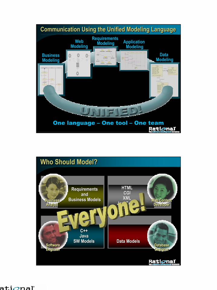
Communication Using the Unified Modeling Language Communication Using the Unified Modeling Language
Data Modeling
Data Modeling
Web Modeling
One language – One tool – One teamOne language – One tool – One team
Application Modeling
Application Modeling
Business Modeling
Requirements Modeling
Requirements Modeling
Who Should Model?Who Should Model?
RequirementsRequirementsandand
Business ModelsBusiness Models
HTMLHTMLCGICGIXMLXML
JavaScriptJavaScript
Data ModelsData Models
C++C++JavaJava
SW ModelsSW ModelsSoftwareEngineerSoftwareEngineer
DatabaseDesignerDatabaseDesigner
Web ContentDeveloper
Web ContentDeveloper
BusinessAnalyst
BusinessAnalyst

7
Host or Target ApplicationHost or Target Application
The Developer’s ViewThe Developer’s View
The Model is The ApplicationThe Model is
The Application
Use Case DiagramUse Case Diagram
Sequence DiagramSequence Diagram
Class DiagramClass DiagramStructure DiagramStructure Diagram
Behavior DiagramBehavior Diagram
Component DiagramComponent Diagram
Deployment DiagramDeployment Diagram
The Unified Modeling LanguageThe Unified Modeling Language

8
UML HistoryUML History1994: Grady Booch and Jim Rumbaugh began unifying their modeling techniques at Rational Software1995: Ivar Jacobson joins team at Rational1996: Consortium of 12 companies formed to oversee UMLJan 1997: Version 1.0 publishedSept 1997: Revised Version 1.1Nov 1997: Object Management Group standardizedVersion 1.4 just acceptedWorking on version 2.0
1994: Grady Booch and Jim Rumbaugh began unifying their modeling techniques at Rational Software1995: Ivar Jacobson joins team at Rational1996: Consortium of 12 companies formed to oversee UMLJan 1997: Version 1.0 publishedSept 1997: Revised Version 1.1Nov 1997: Object Management Group standardizedVersion 1.4 just acceptedWorking on version 2.0
Why is the Word “Model” Important?Why is the Word “Model” Important?Developing software is about developing executable abstractions
An abstraction or view is a modelFor example, a class is an abstraction of a real-world entity or concept
Different stake holders have different abstractionsMarketing has the feature sheetDevelopers have the requirementsTesting have test cases and configurations
There are model types in building a system
Developing software is about developing executable abstractions
An abstraction or view is a modelFor example, a class is an abstraction of a real-world entity or concept
Different stake holders have different abstractionsMarketing has the feature sheetDevelopers have the requirementsTesting have test cases and configurations
There are model types in building a system

9
UML ContextUML ContextIt enables and promotes a
use-case-drivenarchitecture-centriciterativeincremental process that is object oriented and component based
Justification is thatUse cases are used to manage and provide focus for a problem-solving effort. Architecture is used to manage complexity and maintain integrity and focus as a solution to a problem evolves. Iterations and increments are used to repeatedly apply a process to evolve a solution to a problem.
It enables and promotes a use-case-drivenarchitecture-centriciterativeincremental process that is object oriented and component based
Justification is thatUse cases are used to manage and provide focus for a problem-solving effort. Architecture is used to manage complexity and maintain integrity and focus as a solution to a problem evolves. Iterations and increments are used to repeatedly apply a process to evolve a solution to a problem.
Why is UML So Great?Why is UML So Great?Combines best ideas from software engineering, database theory, and system designTechnology agnostic Problem domain agnostic
Extensibility mechanisms allow tailoring to the domainScalable
Recursive, hierarchical decompositionBootstrapping principle
Language that can define itselfHigh information density
VisualPacks a lot into a small space
Combines best ideas from software engineering, database theory, and system designTechnology agnostic Problem domain agnostic
Extensibility mechanisms allow tailoring to the domainScalable
Recursive, hierarchical decompositionBootstrapping principle
Language that can define itselfHigh information density
VisualPacks a lot into a small space

10
UML ModelsUML ModelsModels capture
the structural, or static, features of systems the behavioral, or dynamic, features of systems.
Models have several independent dimensionsEach emphasize particular qualities of a modelEach dimension has a diagram type
Models capturethe structural, or static, features of systems the behavioral, or dynamic, features of systems.
Models have several independent dimensionsEach emphasize particular qualities of a modelEach dimension has a diagram type
UML DiagramsUML DiagramsUse case diagrams depict the functionality of a system. Class and object diagrams for the static structureSequence (collaboration) diagrams for behavior in a scenarioState diagrams for executionActivity diagrams for process descriptions Component diagrams for dependencies between componentsDeployment diagrams for configuration and environment
Use case diagrams depict the functionality of a system. Class and object diagrams for the static structureSequence (collaboration) diagrams for behavior in a scenarioState diagrams for executionActivity diagrams for process descriptions Component diagrams for dependencies between componentsDeployment diagrams for configuration and environment

11
Other Elements of UMLOther Elements of UMLThere are many
Package, sub-system, class, classifier, interface, …We really don’t have the time to discuss thisTalk to your professorsThere are many good books around
There are manyPackage, sub-system, class, classifier, interface, …
We really don’t have the time to discuss thisTalk to your professorsThere are many good books around
USE CASEsUSE CASEsDescribes the proposed functionality of a systemRepresent functional requirementNotation
Use cases: ellipse with action phaseActors is a user of the system or other systems
Describes the proposed functionality of a systemRepresent functional requirementNotation
Use cases: ellipse with action phaseActors is a user of the system or other systems

12
Logical ModelLogical ModelClass and Object DiagramsClass Diagram Notation
3-compartment rectangleRelationship among classes
Object diagram: instance of a class
Accessibility Notation
Class and Object DiagramsClass Diagram Notation
3-compartment rectangleRelationship among classes
Object diagram: instance of a class
Accessibility Notation
Logical Model (continued)Logical Model (continued)Class and Object Relationship
Inheritance: generally describes the hierarchical relationship between classes (family tree).
Class and Object RelationshipInheritance: generally describes the hierarchical relationship between classes (family tree).
Some materials herein are excerpted from The Logical Model by Geoffrey SparksSome materials herein are excerpted from The Logical Model by Geoffrey Sparks

13
Logical Model (continued)Logical Model (continued)Class and Object Relationship
Association: generally relate to one object having an instance of another as an attribute or owning.
Class and Object RelationshipAssociation: generally relate to one object having an instance of another as an attribute or owning.
Some materials herein are excerpted from The Logical Model by Geoffrey SparksSome materials herein are excerpted from The Logical Model by Geoffrey Sparks
Sequence Diagrams (dynamic relationship)Sequence Diagrams (dynamic relationship)illustrates this message passing and the sequence in which it occurs normally within a given usecaseillustrates this message passing and the sequence in which it occurs normally within a given usecase
Some materials herein are excerpted from The Logical Model by Geoffrey SparksSome materials herein are excerpted from The Logical Model by Geoffrey Sparks

14
Logical Model (continued)Logical Model (continued)Class and Object Relationship
Aggregation: generally define whole/part relationships..
Class and Object RelationshipAggregation: generally define whole/part relationships.
.
Some materials herein are excerpted from The Logical Model by Geoffrey SparksSome materials herein are excerpted from The Logical Model by Geoffrey Sparks
Cool Things to do with UMLCool Things to do with UML

15
Do all of this for Multiple LanguagesDo all of this for Multiple LanguagesUML models can be targeted for different languages
Java Microsoft Visual C++Microsoft Visual BasicANSI C++AdaIDLXML-DTDSQL
UML models can be targeted for different languagesJava Microsoft Visual C++Microsoft Visual BasicANSI C++AdaIDLXML-DTDSQL
Keeping the Model and Code SynchronizedKeeping the Model and Code SynchronizedManual model and code synchronization
On-demand synchronizationComplete control as updates occur
Auto synchronizationSource is updated when model is modifiedRational Rose model updated when source is modified
Manual model and code synchronization
On-demand synchronizationComplete control as updates occur
Auto synchronizationSource is updated when model is modifiedRational Rose model updated when source is modified
16
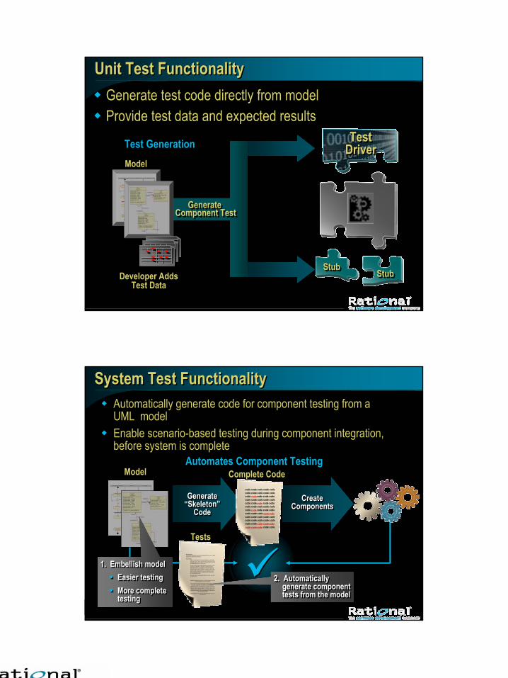
Unit Test FunctionalityUnit Test FunctionalityGenerate test code directly from modelProvide test data and expected resultsGenerate test code directly from modelProvide test data and expected results
Generate Component Test
Generate Component Test
StubStubStubStub
TestDriverTest
DriverModelModel
Test GenerationTest Generation
Developer AddsTest Data
Developer AddsTest Data
System Test FunctionalitySystem Test Functionality
????
Model
Create Components
Create Create ComponentsComponents
Brief Description:The description should briefly convey the role and purpose of the use case. A single paragraph should suffice for this description.
Flow of Events:This use case starts when the actor does something. An actor always initiates use Cases. The use case should describe what the actor does and what the system does in response. It should be phrased in the form of a dialog between the actor and the system.
The use case should describe what happens inside the system, but not how or why. If information is exchanged, be specific about what is passed back and forth. For example, it is not very illuminating to say that the Actor enters customer information; it is better to say the Actor enters the customer’s name and address. A Glossary of Terms is often useful to keep the complexity of the use case manageable; you may want to define things like customer information there, to keep the use case from drowning in details.
Simple alternatives may be presented within the text of the use case. If it only takes a few
and what the system does in response. It should be phrased in the form of a dialog between the actor and the system.
The use case should describe what happens inside the system, but not how or why. If information is exchanged, be specific about what is
passed back and forth. For example, it is not very illuminating to say that the Actor enters customer information; it is better to say the Actor
enters the customer’s name and address. A Glossary of Terms is often useful to keep the complexity of the use case manageable; you may want to define things like customer information there, to keep the use
case from drowning in details.
Simple alternatives may be presented within the text of the use case. If it only takes a few
TestsTests
Generate “Skeleton”
Code
Generate “Skeleton”
Code
code code code code code code code code code code code code code code code code code code code code code code code code code code code code code code code code code code code code code code code code code code code code code code code
code code
Complete Code
code
code
codecodecode
codecodecodecodecodecode
Automates Component TestingAutomates Component Testing
1. Embellish modelEasier testingMore completetesting
1. Embellish modelEasier testingMore completetesting
2. Automatically generate component tests from the model
2. Automatically generate component tests from the model
Automatically generate code for component testing from a UML modelEnable scenario-based testing during component integration, before system is complete
Automatically generate code for component testing from a UML modelEnable scenario-based testing during component integration, before system is complete

17
Ready made design and code solutions for common development tasks
COM, MFC, ATLMTS, ADOASP, DHTML
Fully customizableYou can create your own code templates to automatecommon design and implementation tasks to ensure consistencyin both design and code
Ready made design and code solutions for common development tasks
COM, MFC, ATLMTS, ADOASP, DHTML
Fully customizableYou can create your own code templates to automatecommon design and implementation tasks to ensure consistencyin both design and code
Code Templates For Architecture DesignCode Templates For Architecture Design
Frameworks For Architecture DefinitionFrameworks For Architecture DefinitionFrameworks: Predefined model element sets for modeling specific systems Used to:
Define the architecture of specific types of systemsProvide a set of reusable componentsCreate templates for new models
Simplify development with commercial frameworksPromote reuse and standards with custom user frameworks
Frameworks: Predefined model element sets for modeling specific systems Used to:
Define the architecture of specific types of systemsProvide a set of reusable componentsCreate templates for new models
Simplify development with commercial frameworksPromote reuse and standards with custom user frameworks
18
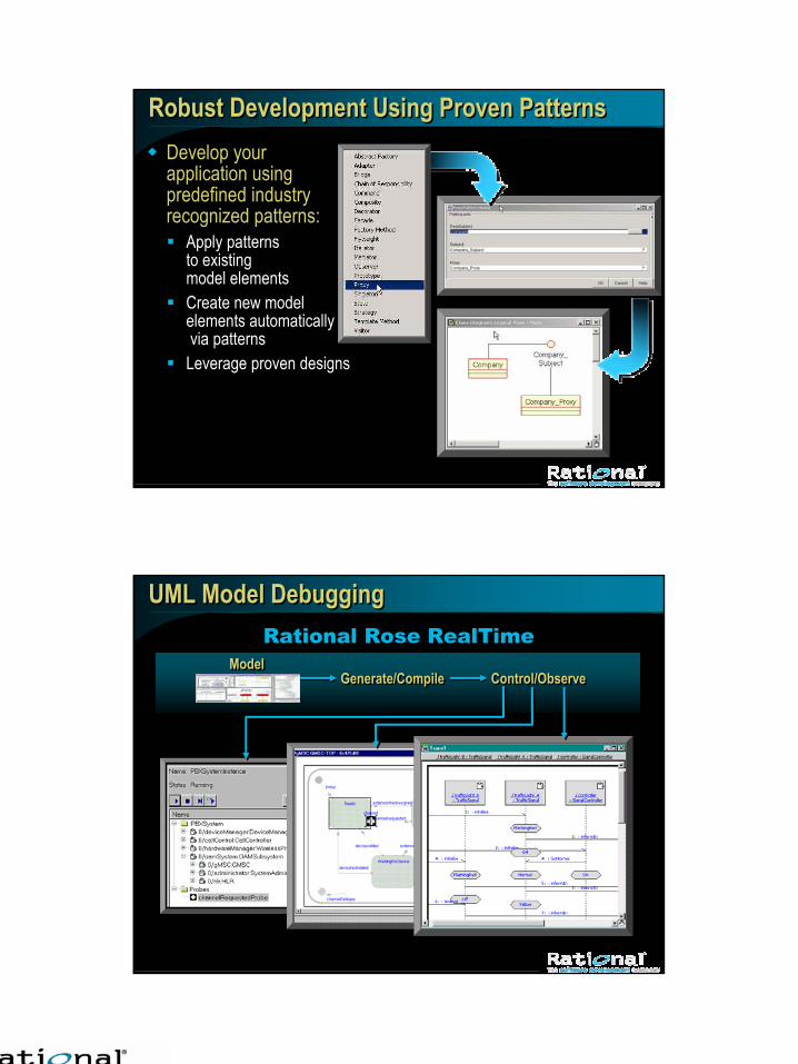
Robust Development Using Proven PatternsRobust Development Using Proven PatternsDevelop your application using predefined industry recognized patterns:
Apply patterns to existing model elementsCreate new model elements automaticallyvia patterns
Leverage proven designs
Develop your application using predefined industry recognized patterns:
Apply patterns to existing model elementsCreate new model elements automaticallyvia patterns
Leverage proven designs
UML Model DebuggingUML Model DebuggingRational Rose RealTime
ModelModelGenerate/CompileGenerate/Compile Control/ObserveControl/Observe

19
Distributed UML DesignsDistributed UML DesignsEnables deployment and visualization of distributed applicationsSupports patterns for creating high-availability applicationsProvides the distributed communication infrastructure
Enables deployment and visualization of distributed applicationsSupports patterns for creating high-availability applicationsProvides the distributed communication infrastructure
COTS Server
Shelf ControllerShelf ControllerCall ServerCall ServerAdministrationAdministration H/W ControlH/W Control
That’s allThat’s all

20
Some Important Web SitesSome Important Web SitesThe SEEDS program will let your college get Rose
http://www.rational.com/corpinfo/college_relations/seed/termscond.jsp
.NET developmenthttp://rational.devx.com/index.htm/CONTENT_ID/5959
Java developmentwww.jroundup.com
Project managementwww.ganthead.com
The SEEDS program will let your college get Rose http://www.rational.com/corpinfo/college_relations/seed/termscond.jsp
.NET developmenthttp://rational.devx.com/index.htm/CONTENT_ID/5959
Java developmentwww.jroundup.com
Project managementwww.ganthead.com

21
“ClearCase is the dominant SCM tool.” Ovum“ClearCase is the dominant SCM tool.” Ovum
No.1 in Visual Modeling, 4 years running1 Rational RoseNo.1 in Visual Modeling, 4 years running1 Rational Rose
No.1 in SCM, 3 years running1 Rational ClearCaseNo.1 in SCM, 3 years running1 Rational ClearCase
“…a major contender as the de facto standard for real-time embedded ...” IDC“…a major contender as the de facto standard for real-time embedded ...” IDCReal-time embedded leadership Rational Rose RealTimeReal-time embedded leadership Rational Rose RealTime
“...the battle for dominance is over: Rational wins.” Ed Yourdon“...the battle for dominance is over: Rational wins.” Ed Yourdon
Driving Standards in Best Practices UML, WebDAVDriving Standards in Best Practices UML, WebDAV“…the company that put the ‘unified’ in modeling languages…” JavaPro“…the company that put the ‘unified’ in modeling languages…” JavaPro
“Easy-to-use...ideal for team based development...” InfoWorld“Easy-to-use...ideal for team based development...” InfoWorldNo.1 in Requirements Management2 Rational RequisiteProNo.1 in Requirements Management2 Rational RequisitePro
1 IDC, 2 Standish1 IDC, 2 Standish
Rational: Ongoing LeadershipRational: Ongoing Leadership