

![Visual Weld Inspection Guidelines Attachment A - …2].pdf · Visual Weld Inspection Guidelines Attachment A ... approved weld inspector shall document weld inspection results using](https://static.fdocuments.net/doc/165x107/5a78aa797f8b9a21538b97b6/visual-weld-inspection-guidelines-attachment-a-2pdfvisual-weld-inspection.jpg)


Languages
Pages
Legal

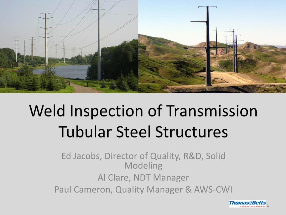
Weld Inspection of Transmission Tubular Steel Structures Ed Jacobs, Director of Quality, R&D, Solid
Modeling Al Clare, NDT Manager
Paul Cameron, Quality Manager & AWS-CWI 1

Objectives
• Framework and shortcomings of AWS D1.1 • Repeatable UT inspection • NDE metallurgical examinations & validations • Recommend a standard
2
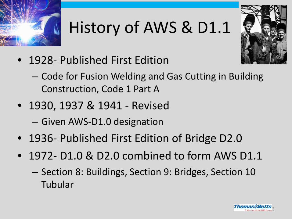
History of AWS & D1.1
• 1928- Published First Edition – Code for Fusion Welding and Gas Cutting in Building
Construction, Code 1 Part A
• 1930, 1937 & 1941 - Revised – Given AWS-D1.0 designation
• 1936- Published First Edition of Bridge D2.0 • 1972- D1.0 & D2.0 combined to form AWS D1.1
– Section 8: Buildings, Section 9: Bridges, Section 10 Tubular
3

History of AWS & D1.1 cont.
• 1988- Bridges group separated – Formed AASHTO/AWS D1.5 – Bridge
Welding Code • 1990’s- Section 10 Tubular removed
– All inspection condensed into Section 6 • Now Clause 6 • Change was significant to Pole Structures
industry
• Currently- AWS D1.1/D1.1M:2010 – 5 year rev. cycle
4

Framework of AWS D1.1
• Known throughout the industry – “All Welding per AWS D1.1”
• Qualifies process and people – Clause 3 & 4
• Discusses alternative means of UT inspection – Annex S
• Inspector Qualification – AWS QC1 & ASNT SNT-TC-1A
• Calibration of UT equipment – Clause 6 Part F – Based on CRT technology
5
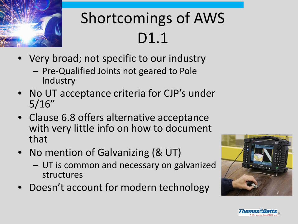
Shortcomings of AWS D1.1
• Very broad; not specific to our industry – Pre-Qualified Joints not geared to Pole
Industry • No UT acceptance criteria for CJP’s under
5/16” • Clause 6.8 offers alternative acceptance
with very little info on how to document that
• No mention of Galvanizing (& UT) – UT is common and necessary on galvanized
structures • Doesn’t account for modern technology
6

Shortcomings of AWS D1.1 cont.
• Evaluation from 1 face (UT) – Corner or T- Joint ≤ 1.5 inch
• Needs more consideration – CVN
• Identifies all defects – Finite Element Analysis (FEA) – Should concentrate on critical
defects • Frequency of CJP UT inspection
– 10% vs. 100%
7
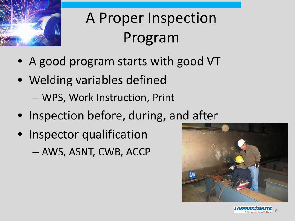
A Proper Inspection Program
• A good program starts with good VT • Welding variables defined
– WPS, Work Instruction, Print
• Inspection before, during, and after • Inspector qualification
– AWS, ASNT, CWB, ACCP
8

A Proper Inspection Program cont.
• If more than VT required – VT then UT
• Minimize variation between inspectors (VT & UT)
9

T&B Destructive Testing Results and Validation of NDE
10
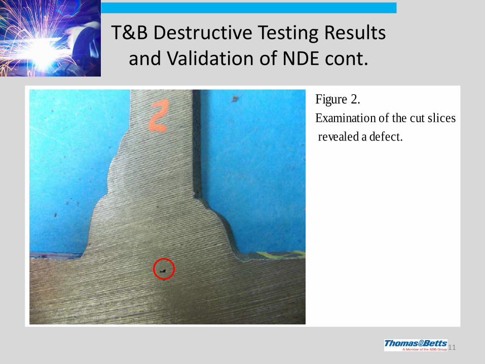
T&B Destructive Testing Results and Validation of NDE cont.
11
Figure 2. Examination of the cut slices revealed a defect.
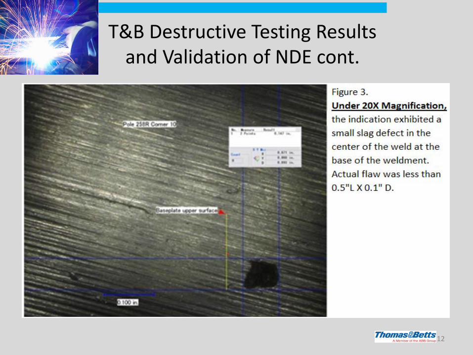
T&B Destructive Testing Results and Validation of NDE cont.
12
Results
• Indication rejectable by UT (AWS D1.1) • Major reduction in size and geometry
reported (UT 2.0”L x 0.12”D vs. Actual 0.5”L x 0.1”D)
• No effect on structural integrity of pole
13
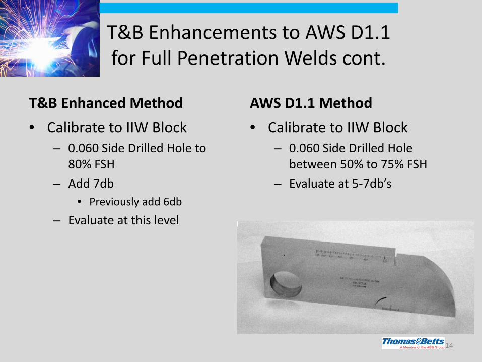
T&B Enhancements to AWS D1.1 for Full Penetration Welds cont.
T&B Enhanced Method • Calibrate to IIW Block
– 0.060 Side Drilled Hole to 80% FSH
– Add 7db • Previously add 6db
– Evaluate at this level
AWS D1.1 Method • Calibrate to IIW Block
– 0.060 Side Drilled Hole between 50% to 75% FSH
– Evaluate at 5-7db’s
14
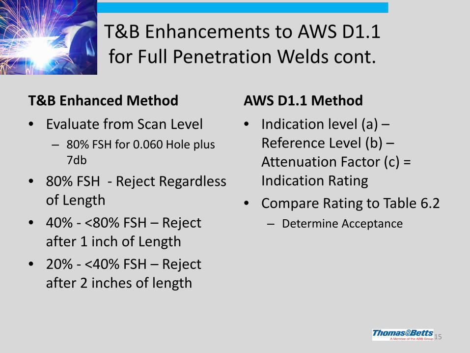
T&B Enhancements to AWS D1.1 for Full Penetration Welds cont.
T&B Enhanced Method • Evaluate from Scan Level
– 80% FSH for 0.060 Hole plus 7db
• 80% FSH - Reject Regardless of Length
• 40% - <80% FSH – Reject after 1 inch of Length
• 20% - <40% FSH – Reject after 2 inches of length
AWS D1.1 Method • Indication level (a) –
Reference Level (b) – Attenuation Factor (c) = Indication Rating
• Compare Rating to Table 6.2 – Determine Acceptance
15

T&B Enhancements to AWS D1.1 for Full Penetration Welds cont.
T&B Enhanced Method • Add 2db per inch after 2
Inch of Sound Path – Was “Add 2db per inch after 5
Inch of Sound Path” – Added “Skip Charts” to
Standard for easy reference.
AWS D1.1 Method • Calculated using Sound Path
16
Projected

T&B Enhancements to AWS D1.1 for Full Penetration Welds cont.
T&B Enhanced Method • Length Evaluation
– Measured from Center of Transducer
• From Max Indication: – Scan Left and Right until
indication drops below 10%
AWS D1.1 Method • Length Evaluation
– Measured from Center of Transducer
• From Max Indication: – Scan Left and Right until
indication drops by 50% (6db) – This could still be 37.5% FSH – This would not be less than
25% FSH
17

T&B Enhancements to AWS D1.1 for Full Penetration Welds cont.
T&B Advantage • Meets
– AWS Requirements
• Exceeds – More Critical on Longer
Indications – Allows Evaluations after 2nd
Leg – Allows Evaluation with Both a
70° and 45° Transducer
D1.1 Disadvantage • No Acceptance Criteria for
Material Under 5/16 inch • No Criteria for Coated
Material – Galvanized
• Evaluation in the 1st and 2nd Legs Only – On thinner material the 2nd
Leg may not be out from under the transducer
18
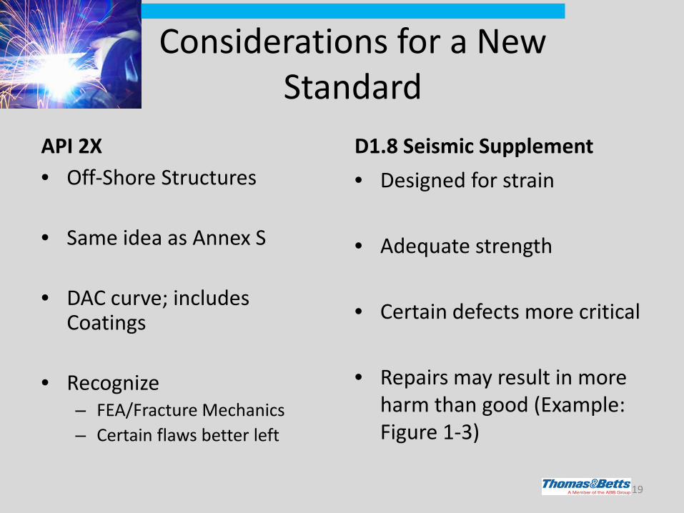
Considerations for a New Standard
API 2X • Off-Shore Structures
• Same idea as Annex S
• DAC curve; includes
Coatings • Recognize
– FEA/Fracture Mechanics – Certain flaws better left
D1.8 Seismic Supplement • Designed for strain
• Adequate strength
• Certain defects more critical
• Repairs may result in more
harm than good (Example: Figure 1-3)
19

Conclusions
• The long-term approach for the industry is to work within our industry committees to collectively develop, as AWS D1.1 recommends, a standard suitable specifically for tubular steel transmission structures.
• Refer to Paper, “Baseplate and Flange Weld Inspection of Tubular Steel Transmission Structures”
20
Top Related