


Languages
Pages
Legal


158 CATALOG | Photoelectric Sensors
• Machine Learning Assisted Setting• No vision Tools programming required• No inspection threshold adjustment• No need of skilled installers and users• Fast and Easy Setting like standard photosensor• Deterministic response time 50ms• Reduced cost of ownership and maintenance• TEACH Button and comprehensive UI with 5 status LEDs• Electronic focus control• 50...150mm operating distance• Bright and visible Red LED pointer• Powerful white polarized light illuminator• Green/Red LED Spot for GOOD/NO GOOD part• Ethernet point to point communication available• Easy and Intuitive WEB Server GUI for maintenance and job setting• Easy output interface photosensor like
AI enabled
SVSC ATA L O G S E C T I O N
APPLICATIONS• Processing and packaging machinery• Transport and handling lines• Assembly lines• Food & Beverage• Bottling lines• Machines for the Cosmetic and Pharmaceutical sector
THE SMART VISION SENSOR ENABLED WITH A.I. AND EMPOWERED BY MACHINE LEARNING ASSISTED SETTING ALGORITHMS. SIMPLY CLEVER SOLUTION FOR ALL YOUR PRESENCE AND ORIENTATION OBJECT DETECTION APPLICATIONS
ELECTRICAL FEATURES
PowerSupply Voltage (Vdc)Consumption (A) Max.
10 to 30 Vdc0.40 - 0.14 A (4.2 W)
Communication InterfaceEthernet 1 10/100 Mbit/s
Inputs Opto-coupled and polarity insensitiveMax. Voltage 30 VdcMax. Input Current 10 mAOutput Type Push-pull, NPN or PNP, short circuit protectedOutputs 3 Outputs (DATA VALID, GOOD, NO GOOD)
VOUT (ILOAD = 0 mA) Max. 30 Vdc
VOUT (ILOAD = 100 mA) Max. 3 Vdc
ILOAD Max. 100 mA
Smart-VSVISION SENSORS
1 The embedded Ehternet interface is intended for configuration only through connection to the device IP. Point-to-Point connection is recommended.
MLAS - Machine Learning Assisted Setting

159CATALOG | Photoelectric Sensors
Optical and Detection FeaturesOperating distance 50...150 mmView angle 19°FOV area @ 50 mm 22 mm (H) x 16 mm (V)FOV area @ 150 mm 55 mm (H) x 41 mm (V)Response Time 50 msMax. Image to handle (GOOD+NO GOOD) 6 imagesMax pcs per second 20 pcs per secondActive Area Resolution 320x240 pixelsIlluminator White LED polarized
Phisical FeaturesDimensionsStd SPH connector at 0°Std SPH connector at 90°
H x W x L78 x 47 x 38 mm (3.1 x 1.9 x 1.5 in)58 x 47 x 58 mm (2.3 x 1.9 x 2.3 in)
Weight 173 g (6.1 oz)Material Aluminum with plastic PMMA protective window
Environmental FeaturesOperating Temperature 2 -10 to 50 °C (14 to 122 °F)Storage Temperature -20 to 70 °C (-4 to 148 °F)Max. Humidity 90% non-condensing
Vibration Resistance 14 mm @ 2 to 10 Hz; 1.5 mm @ 13 to 55 Hz; 2 g @ 70 to 500 Hz; 2 hours on each axis
Shock Resistance 30 g; 11 ms; 3 shocks on each axisProtection Class 3 IP65 and IP67
TECHNICAL DATA
DIMENSIONSSmart-VS STRAIGHT CONNECTORS
AXIS
AXIS
1 The embedded Ehternet interface is intended for configuration only through connection to the device IP. Point-to-Point connection is recommended.2 High ambient temperature applications should use metal mounting bracket for heat dissipation.3 When correctly connected (fully tightened) to IP67 cables with seals.

160 CATALOG | Photoelectric Sensors
SMART-VS 90° CONNECTORS
CONNECTIONS
M12 8-pin Standard Ethernet Network Connector Pinout
Pin Name Function
12345678
TX+TX-RX+RX-ncncncnc
Transmit data (positive pin)Transmit data (negative pin)Receive data (positive pin)Receive data (negative pin)
Not ConnectedNot ConnectedNot ConnectedNot Connected
M12 17-pin Power, COM, and I/O Connector PinoutPin Nome Colore Funzione
12
Connector case
VdcGND
Chassis
MarroneBlu
Power supply input voltage +Power supply input voltage -
Connector case provides electricalconnection to the chassis
65
133
I1AI1BI2AI2B
YellowPink
White/GreenWhite
I1A Trigger Input A (Polarity Insensitive)I1B Trigger Input B (Polarity Insensitive)
I2A Remote Teach A (Polarity Insensitive)I2B Remote Teach A (Polarity Insensitive)
9 O1* Red Data Valid PP
8 O2* Grey GOOD Output PP
16 O3* Yellow/Brown NO-GOOD Output PP
161CATALOG | Photoelectric Sensors
13
6
87
9
1
5
2
1
3
3
11
4
1011
12
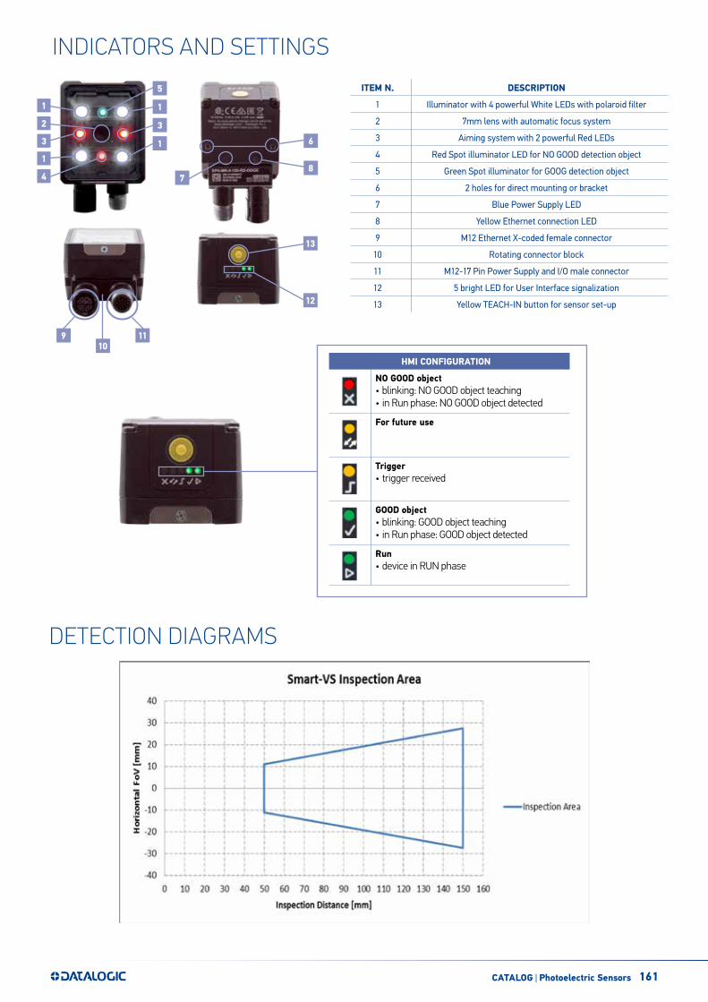
INDICATORS AND SETTINGS
DETECTION DIAGRAMS
ITEM N. DESCRIPTION
1 Illuminator with 4 powerful White LEDs with polaroid filter
2 7mm lens with automatic focus system
3 Aiming system with 2 powerful Red LEDs
4 Red Spot illuminator LED for NO GOOD detection object
5 Green Spot illuminator for GOOG detection object
6 2 holes for direct mounting or bracket
7 Blue Power Supply LED
8 Yellow Ethernet connection LED
9 M12 Ethernet X-coded female connector
10 Rotating connector block
11 M12-17 Pin Power Supply and I/O male connector
12 5 bright LED for User Interface signalization
13 Yellow TEACH-IN button for sensor set-up
HMI CONFIGURATION
NO GOOD object• blinking: NO GOOD object teaching• in Run phase: NO GOOD object detected
For future use
Trigger• trigger received
GOOD object• blinking: GOOD object teaching• in Run phase: GOOD object detected
Run• device in RUN phase

162 CATALOG | Photoelectric Sensors
100 Matrix 220
Chapter 6Reading Features
FOV CalculationUse the data in the following table to calculate the FOV for your application, referring to Figure 81 and the formula below.
Focal Length F/# d0
View Angle Horizontal
View Angle Vertical
View Angle Diagonal
Min Read-ing Distance
mm
7 mm F/4 11 mm 38° 29° 48° 40 mm
12 mm F/5 4 mm 24° 18° 30° 40 mm
The viewing angle has a tolerance of 1° depending on the reading distance.
FOVx = 2 [ (d + d0) * tan (x/2) ]
where:FFOOVVxx = horizontal, vertical or diagonal FOVxx = horizontal, vertical or diagonal viewing angles.dd = reading distance (in mm) from window surface to code surfacedd00 = offset (in mm) from center of lens to external window surface
FFiigguurree 8811 -- RReeaaddiinngg DDiissttaannccee RReeffeerreenncceess
FIELD OF VIEW CALCULATIONUse the data in the following table to calculate the FOV for your application, referring to the draw and the formula below.
The viewing angle has a tolerance of ±1° depending on the reading distance.
FOVx = 2 [ (d + d0) * tan (αx/2) ]where:FOVx = horizontal, vertical or diagonal FOVαx = horizontal, vertical or diagonal viewing angles.d = reading distance (in mm) from window surface to code surfaced0 = offset (in mm) from center of lens to external window surface
Example:The FOV at a reading distance of 100 mm is:FOVH = 2[(100mm + 11mm)*tan(19°/2)] 37mmFOVV = 2[(100mm + 11mm)*tan(14,5°/2)] 28mm
D0 View angle horizontal View angle vertical View angle diagonal Min Reading Distance mm
11 mm 19° 14,5° 24° 50 mm
OPERATING PRINCIPLES AND APPLICATIONSSmart-VS simply clever
The Smart-VS is a Smart vision sensor simple and clever. It is simple outside since it can be handled and used like a standard photoelectric sensor but powerful and smart inside with a multiprocessor platform supporting and embedding the Artificial Intelligence technology. Its customized machine learning algorithms are empowering the detection system core enabling very complex and accurate object classification ensuring at same time a very simple setting procedure by the user
The user does not have to take care about programming or setting threshold of different vision tools, all these complex functionalities are operated by the Smart-VS “brain”.
The detection function will be accomplished with three easy and fast steps. The quick step is the GOOD condition teaching the second step is no good condition teaching the third will turn the sensor in learning and normal run status ready to detect GOOD or NO GOOD objects. The user will just present the objects in front of sensor eye and push the button to change acquisition steps until the sensor will start to think and act.
The sensor is especially suited for all the applications where it is needed to solve detection between two well specified object condition classes, like presence or absence of a specific feature or object orientation respect two sides, teaching the sensor with GOOD and NO GOOD condition.
STEP 1TEACH
GOOD caseSTEP 3
LEARN and RUNSTEP 2TEACH
NO GOOD case
163CATALOG | Photoelectric Sensors
Application name
Check label presence
Cap orientation
Cap presence
Check printing on label
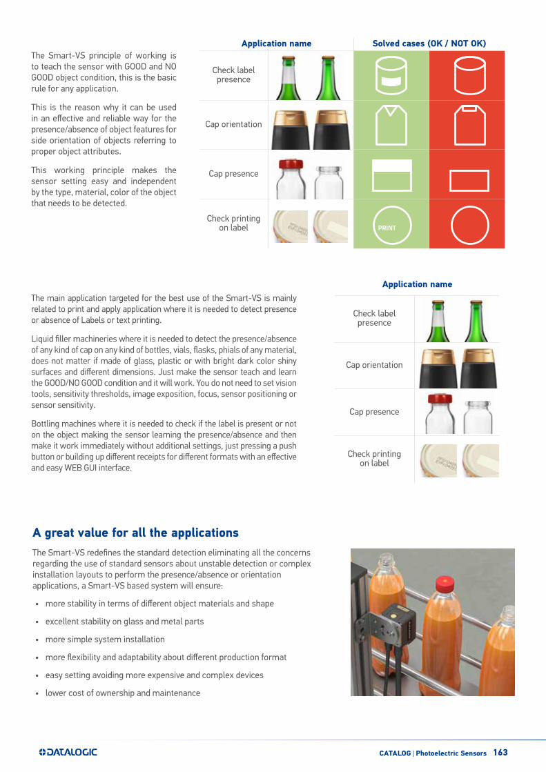
The Smart-VS principle of working is to teach the sensor with GOOD and NO GOOD object condition, this is the basic rule for any application.
This is the reason why it can be used in an effective and reliable way for the presence/absence of object features for side orientation of objects referring to proper object attributes.
This working principle makes the sensor setting easy and independent by the type, material, color of the object that needs to be detected.
The main application targeted for the best use of the Smart-VS is mainly related to print and apply application where it is needed to detect presence or absence of Labels or text printing.
Liquid filler machineries where it is needed to detect the presence/absence of any kind of cap on any kind of bottles, vials, flasks, phials of any material, does not matter if made of glass, plastic or with bright dark color shiny surfaces and different dimensions. Just make the sensor teach and learn the GOOD/NO GOOD condition and it will work. You do not need to set vision tools, sensitivity thresholds, image exposition, focus, sensor positioning or sensor sensitivity.
Bottling machines where it is needed to check if the label is present or not on the object making the sensor learning the presence/absence and then make it work immediately without additional settings, just pressing a push button or building up different receipts for different formats with an effective and easy WEB GUI interface.
Application name Solved cases (OK / NOT OK)
Check label presence
Cap orientation
Cap presence
Check printing on label PRINT
A great value for all the applications The Smart-VS redefines the standard detection eliminating all the concerns regarding the use of standard sensors about unstable detection or complex installation layouts to perform the presence/absence or orientation applications, a Smart-VS based system will ensure:
• more stability in terms of different object materials and shape
• excellent stability on glass and metal parts
• more simple system installation
• more flexibility and adaptability about different production format
• easy setting avoiding more expensive and complex devices
• lower cost of ownership and maintenance

164 CATALOG | Photoelectric Sensors
The Smart-VS is very easy and simple to integrate in any application, it can be implemented like a sensor product, but it is much simpler than a smart camera or an ordinary smart sensor.
It is needed to provide a trigger signal by machine electrical phase or an external simple sensor or an encoder. The PC or Ethernet based terminal is an option needed to change configuration of the sensor (once a time) or for more complex set-up where it is needed to change and/or add job setting through the web interface with a browser, in most cases the need to have this connection is not necessary. The web interface can be a useful tool in case of trouble shooting
SMART-VS SETTING METHODSEasy and Comprehensive system integration
WEB INTERFACE
The Smart-VS is provided of a WEB Server User interface for an easy set-up and setting. This is a good option feature when it is needed to setup and change different production jobs depending on variable production format. The information are complete and shown in a clear layout.

165
MODEL SELECTION AND ORDER INFORMATION
ACCESSORIES
MODEL DESCRIPTION OPTIC ILLUMINATOR I/O ORDER N°
Smart-VS-MR-5-150-WH-O SVS WP 150mm OUT 7mm White polarized 3Out + 2In + ETH 959971320
CATEGORY PART NUMBER DESCRIPTION
Cables
93A050076 CAB-GD03 M12 F/L 3M Free wires
93A050077 CAB-GD05 M12 F/L 5M Free wires
93A050122 M12-IP67 GIGA Ethernet Cable X-Coded (1M)
93A050123 M12-IP67 GIGA Ethernet Cable X-Coded (3M)
93A050124 M12-IP67 GIGA Ethernet Cable X-Coded (5M)
93A050128 Adapter Cable GIGA Ethernet X-Coded M12 to RJ45
93A050129 Adapter Cable GIGA Ethernet X-Coded M12 to D-Coded
Bracket 93ACC0230 BK-22-000 Fixing Bracket M220 Body
BK-22-000 Fixing Bracket
The company endeavours to continuously improve and renew its products; for this reason the technical data and contents of this catalogue may undergo variations without prior notice. For correct installation and use, the company can guarantee only the data indicated in the instruction manual supplied with the products. Product and Company names and logos referenced may be either trademarks or registered trademarks of their respective companies. We reserve the right to make modifications and improvements.
DATALOGIC PRODUCT OFFERING
Stationary Industrial Scanners
Safety Light Curtains
Safety Laser Scanner
Laser Marking Systems
Mobile Computers Vision Systems
Sensors Hand Held scanners
Rev. 00, 04/2020
Top Related