


Languages
Pages
Legal

Use of FTDI devices in life support and/or safety applications is entirely at the user’s risk, and the user agrees to defend, indemnify and hold FTDI harmless from any and all damages, claims, suits
or expense resulting from such use.
Future Technology Devices International Limited (FTDI) Unit 1, 2 Seaward Place, Glasgow G41 1HH, United Kingdom Tel.: +44 (0) 141 429 2777 Fax: + 44 (0) 141 429 2758
Web Site: http://ftdichip.com
Copyright © 2014 Future Technology Devices International Limited
Application Note
AN_332
VI800A Ethernet - PoE
Sample Application
Version 1.0
Issue Date: 2014-10-23
This document introduces a sample application to demonstrate the VI800A-ETH and
VI800A–PoE modules. These accessory modules connect to the VM800P series of
boards and provide either Ethernet connectivity (VI800A-ETH) or Ethernet
connectivity with Power over Ethernet capability (VI800A-PoE).
Application note
AN_332 VI800A Ethernet - PoE Sample Application Version 1.0
Document Reference No.: FT_001059 Clearance No.: FTDI#419
2 Product Page
Document Feedback Copyright © 2014 Future Technology Devices International Limited
Table of Contents
1 Introduction .................................................................... 3
1.1 Audience ................................................................................... 3
1.2 Scope ........................................................................................ 3
2 Overview ......................................................................... 4
2.1 Hardware .................................................................................. 4
2.2 Architecture .............................................................................. 4
2.3 Hardware requirement .............................................................. 5
2.4 Software requirement ............................................................... 5
3 Software package introduction ....................................... 6
3.1 Folder introduction .................................................................... 6
3.2 Dependency ............................................................................... 6
4 Setup Steps ..................................................................... 7
4.1 Preparing Hardware .................................................................. 7
5 WebClient Application ................................................... 13
5.1 Overview ................................................................................. 13
5.1.1 Ethernet class .......................................................................................... 13
5.1.2 IPAddress class ........................................................................................ 14
5.1.3 Client class .............................................................................................. 14
5.2 Flowchart ................................................................................ 17
6 Application execution ................................................... 18
7 Contact Information ...................................................... 21
Appendix A– References .................................................... 22
Document References ...................................................................... 22
Acronyms and Abbreviations ........................................................... 22
Appendix B – List of Figures .............................................. 23
List of Figures .................................................................................. 23
Appendix C – Revision History ........................................... 24
Internal Revision History ................................................... 25
Application note
AN_332 VI800A Ethernet - PoE Sample Application Version 1.0
Document Reference No.: FT_001059 Clearance No.: FTDI#419
3 Product Page
Document Feedback Copyright © 2014 Future Technology Devices International Limited
1 Introduction
This application demonstrates a simple application for the VI800A-ETH and VI800A-POE modules.
The application gives a basic understanding of the plug-in board’s features. The sample application
is compatible with VM800P platforms.
Users can refer to the source code of the sample application, and then run the code to observe the
demonstration. Editing the code is also encouraged to help learn the features of the plug-in
module.
This document shows how to set up and use the sample application with the FTDI VM800P
development kits in relation to an Arduino IDE.
For further details on the plug-in modules, please refer to the datasheets below:
VI800A_ETH DS_VI800A-ETH.pdf
VI800A_POE DS_VI800A-POE.pdf
To learn more about the Arduino IDE, please visit http://www.arduino.cc
Note: This application note uses sample application code and library API definitions/usage based
on the Arduino IDE 1.0.5.
1.1 Audience
This document assumes that the reader is familiar with the VI800A-ETH or VI800A-PoE module
features and operation as described in the module datasheets. In addition, familiarity of the
Arduino IDE and C/C++programming language is required to understand the sample application
source code. Familiarity with SPI protocol (for the communication between VM800P and the
module) and with Ethernet and/or PoE are also assumed.
1.2 Scope
The Sample Application mentioned in this document is part of the Arduino IDE (1.0.5) and runs on
a VM800P platform with the Ethernet/PoE board attached. The source code and supporting files are
available through the Examples menu of the Arduino IDE.
Application note
AN_332 VI800A Ethernet - PoE Sample Application Version 1.0
Document Reference No.: FT_001059 Clearance No.: FTDI#419
4 Product Page
Document Feedback Copyright © 2014 Future Technology Devices International Limited
2 Overview
2.1 Hardware
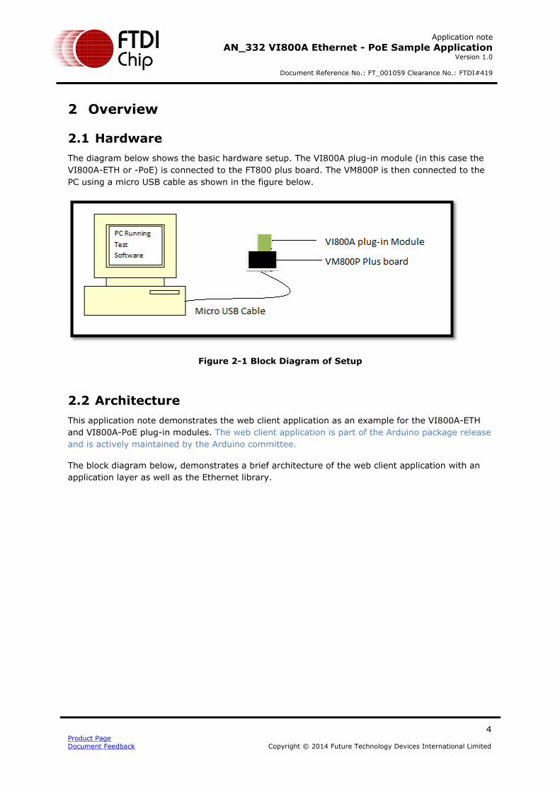
The diagram below shows the basic hardware setup. The VI800A plug-in module (in this case the
VI800A-ETH or -PoE) is connected to the FT800 plus board. The VM800P is then connected to the
PC using a micro USB cable as shown in the figure below.
Figure 2-1 Block Diagram of Setup
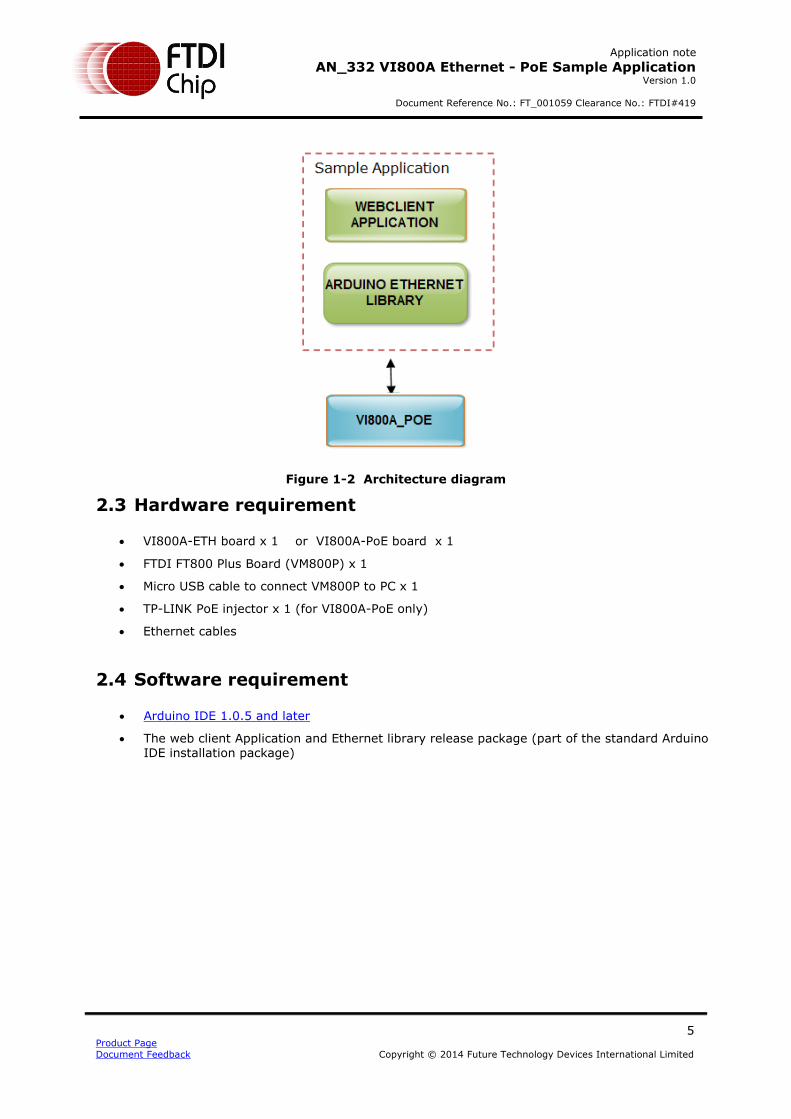
2.2 Architecture
This application note demonstrates the web client application as an example for the VI800A-ETH
and VI800A-PoE plug-in modules. The web client application is part of the Arduino package release
and is actively maintained by the Arduino committee.
The block diagram below, demonstrates a brief architecture of the web client application with an
application layer as well as the Ethernet library.
Application note
AN_332 VI800A Ethernet - PoE Sample Application Version 1.0
Document Reference No.: FT_001059 Clearance No.: FTDI#419
5 Product Page
Document Feedback Copyright © 2014 Future Technology Devices International Limited
Figure 1-2 Architecture diagram
2.3 Hardware requirement
VI800A-ETH board x 1 or VI800A-PoE board x 1
FTDI FT800 Plus Board (VM800P) x 1
Micro USB cable to connect VM800P to PC x 1
TP-LINK PoE injector x 1 (for VI800A-PoE only)
Ethernet cables
2.4 Software requirement
Arduino IDE 1.0.5 and later
The web client Application and Ethernet library release package (part of the standard Arduino IDE installation package)
Application note
AN_332 VI800A Ethernet - PoE Sample Application Version 1.0
Document Reference No.: FT_001059 Clearance No.: FTDI#419
6 Product Page
Document Feedback Copyright © 2014 Future Technology Devices International Limited
3 Software Package Introduction
This section describes the folder structure of the web client application that is part of the standard
Arduino release package.
3.1 Folder introduction
The web client application can be found at “\arduino-1.x.x\libraries\Ethernet\examples\WebClient",
which contains the source code and project file "WebClient.ino".
3.2 Dependency
The Web client Application uses the SPI library and Ethernet library provided by Arduino and is
supplied with Arduino IDE. Please check the Arduino website for details.
Application note
AN_332 VI800A Ethernet - PoE Sample Application Version 1.0
Document Reference No.: FT_001059 Clearance No.: FTDI#419
7 Product Page
Document Feedback Copyright © 2014 Future Technology Devices International Limited
4 Setup Steps
4.1 Preparing Hardware
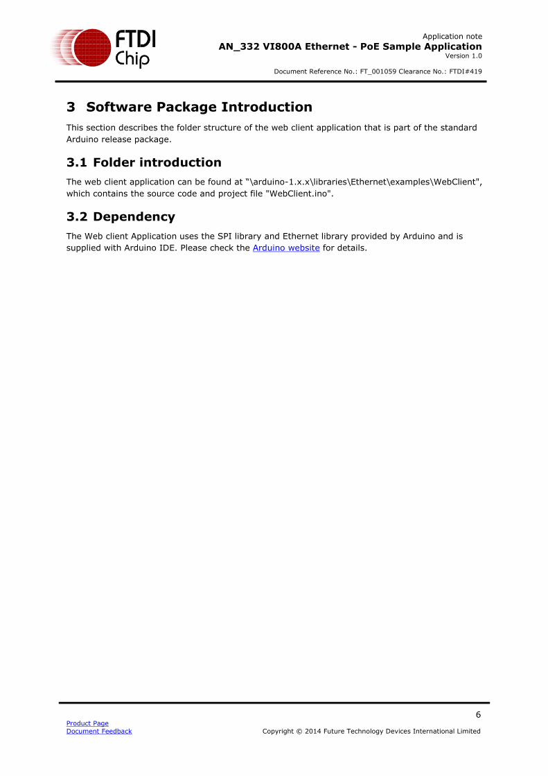
1. Before making any connections, refer to the following screenshot of the FT800 Plus board (VM800P). There are two Daughter Card connectors (coloured red in the image below).
The VI800A-ETH or the VI800A-PoE Plug-In module must be connected to the right-hand side connector (J6).
Figure 2-1 VM800P Board
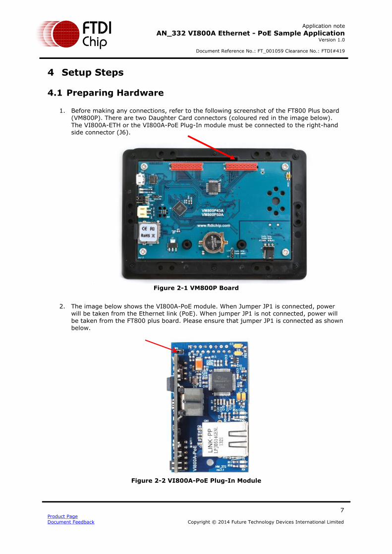
2. The image below shows the VI800A-PoE module. When Jumper JP1 is connected, power
will be taken from the Ethernet link (PoE). When jumper JP1 is not connected, power will be taken from the FT800 plus board. Please ensure that jumper JP1 is connected as shown below.
Figure 2-2 VI800A-PoE Plug-In Module
Application note
AN_332 VI800A Ethernet - PoE Sample Application Version 1.0
Document Reference No.: FT_001059 Clearance No.: FTDI#419
8 Product Page
Document Feedback Copyright © 2014 Future Technology Devices International Limited
3. Now connect the VI800A-PoE to the VM800P plus board as shown below.
Figure 2-3 POE connected to VM800P
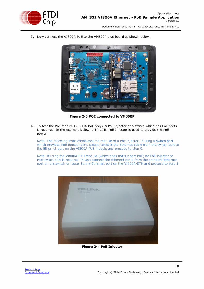
4. To test the PoE feature (VI800A-PoE only), a PoE injector or a switch which has PoE ports is required. In the example below, a TP-LINK PoE Injector is used to provide the PoE power. Note: The following instructions assume the use of a PoE injector, if using a switch port which provides PoE functionality, please connect the Ethernet cable from the switch port to
the Ethernet port on the VI800A-PoE module and proceed to step 9. Note: If using the VI800A-ETH module (which does not support PoE) no PoE injector or PoE switch port is required. Please connect the Ethernet cable from the standard Ethernet
port on the switch or router to the Ethernet port on the VI800A-ETH and proceed to step 9.
Figure 2-4 PoE Injector
Application note
AN_332 VI800A Ethernet - PoE Sample Application Version 1.0
Document Reference No.: FT_001059 Clearance No.: FTDI#419
9 Product Page
Document Feedback Copyright © 2014 Future Technology Devices International Limited
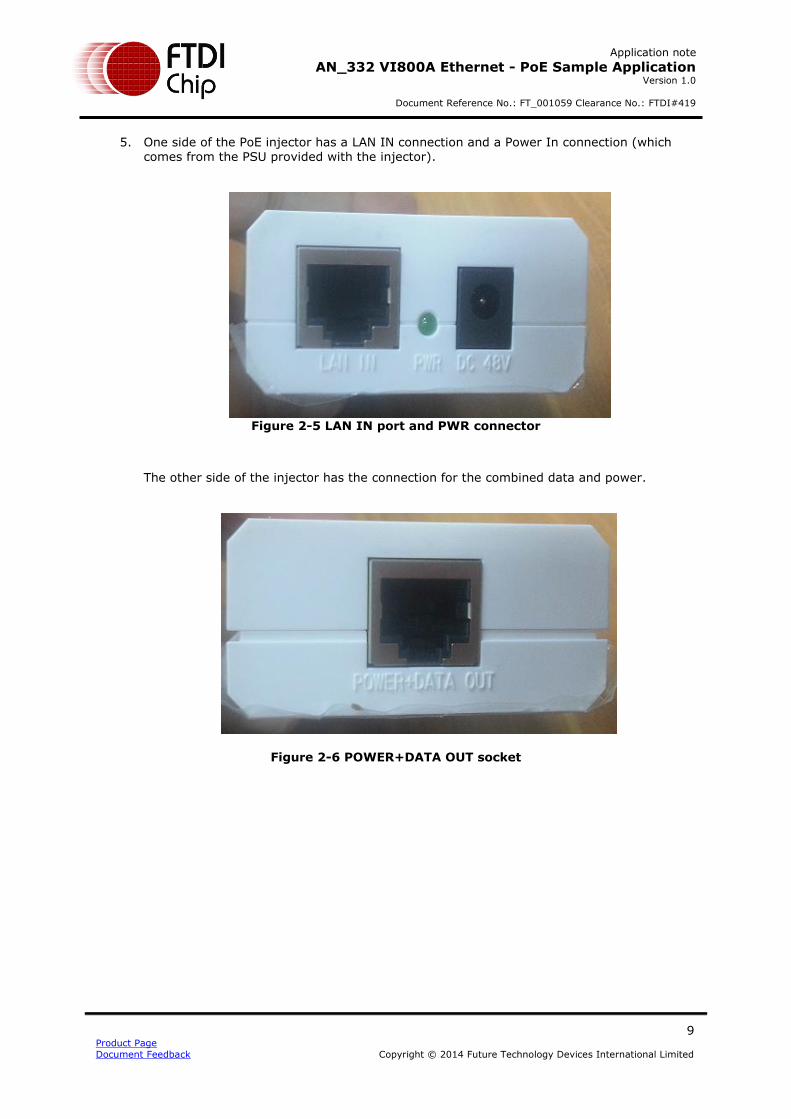
5. One side of the PoE injector has a LAN IN connection and a Power In connection (which comes from the PSU provided with the injector).
Figure 2-5 LAN IN port and PWR connector
The other side of the injector has the connection for the combined data and power.
Figure 2-6 POWER+DATA OUT socket

Application note
AN_332 VI800A Ethernet - PoE Sample Application Version 1.0
Document Reference No.: FT_001059 Clearance No.: FTDI#419
10 Product Page
Document Feedback Copyright © 2014 Future Technology Devices International Limited
6. First of all, the power supply is connected to the PoE injector as shown below, and the green power LED illuminates.
Figure 2-7 Power given to power injector
7. Then, using a standard Ethernet cable, connect the PoE injector to the VI800A-PoE. Connect one end to the 'POWER + DATA OUT' of the POE injector, and the other end to the VI800A-POE module’s Ethernet port.
Figure 2-8 POWER+DATA OUT connection

Application note
AN_332 VI800A Ethernet - PoE Sample Application Version 1.0
Document Reference No.: FT_001059 Clearance No.: FTDI#419
11 Product Page
Document Feedback Copyright © 2014 Future Technology Devices International Limited
8. Connect the Ethernet cable from the network to the PoE injector. Connect one end of an Ethernet cable to the 'LAN IN' of the PoE injector and the other end to a port on the Network/Router.
9. After making these connections, Tx, Rx LEDs should be on, as shown below, as the PoE is
getting power over Ethernet. The FXD LED should also be on.
Figure 2-9 LAN IN connection
The FDX LED is shown in the following screenshot.
Figure 2-10 FXD LED ON
Application note
AN_332 VI800A Ethernet - PoE Sample Application Version 1.0
Document Reference No.: FT_001059 Clearance No.: FTDI#419
12 Product Page
Document Feedback Copyright © 2014 Future Technology Devices International Limited
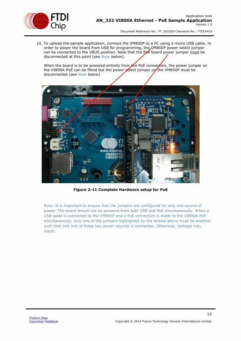
10. To upload the sample application, connect the VM800P to a PC using a micro USB cable. In order to power the board from USB for programming, the VM800P power select jumper can be connected to the VBUS position. Note that the PoE board power jumper must be disconnected at this point (see Note below).
When the board is to be powered entirely from the PoE connection, the power jumper on the VI800A-PoE can be fitted but the power select jumper on the VM800P must be disconnected (see Note below)
Figure 2-11 Complete Hardware setup for PoE
Note: It is important to ensure that the jumpers are configured for only one source of
power. The board should not be powered from both USB and PoE simultaneously. When a
USB cable is connected to the VM800P and a PoE connection is made to the VI800A-PoE
simultaneously, only one of the jumpers highlighted by the arrows above must be enabled
such that only one of these two power sources is connected. Otherwise, damage may
result.
Application note
AN_332 VI800A Ethernet - PoE Sample Application Version 1.0
Document Reference No.: FT_001059 Clearance No.: FTDI#419
13 Product Page
Document Feedback Copyright © 2014 Future Technology Devices International Limited
5 WebClient Application
5.1 Overview
This simple application is used to demonstrate an application with Arduino’s Ethernet library.
A brief description of the Ethernet library APIs which are used in the WebClient application is given in the following sections.
5.1.1 Ethernet class
5.1.1.1 Ethernet.begin()
Description
Initializes the ethernet library and network settings.
With version 1.0, the library supports DHCP. When using Ethernet.begin(mac) with the proper network
setup, the Ethernet shield will automatically obtain an IP address. This increases the sketch size
significantly.
Syntax
Ethernet.begin(mac);
Ethernet.begin(mac, ip);
Ethernet.begin(mac, ip, dns);
Ethernet.begin(mac, ip, dns, gateway);
Ethernet.begin(mac, ip, dns, gateway, subnet);
Parameters
mac: the MAC (Media access control) address for the device (array of 6 bytes). This is the Ethernet
hardware address of your shield.
ip: the IP address of the device (array of 4 bytes)
dns: the IP address of the DNS server (array of 4 bytes). optional: defaults to the device IP
address with the last octet set to 1
gateway: the IP address of the network gateway (array of 4 bytes). optional: defaults to the
device IP address with the last octet set to 1
subnet: the subnet mask of the network (array of 4 bytes). optional: defaults to 255.255.255.0
Returns
The DHCP version of this function, Ethernet.begin(mac), returns an int: 1 on a successful DHCP
connection, 0 on failure. The other versions don't return anything.
Application note
AN_332 VI800A Ethernet - PoE Sample Application Version 1.0
Document Reference No.: FT_001059 Clearance No.: FTDI#419
14 Product Page
Document Feedback Copyright © 2014 Future Technology Devices International Limited
5.1.2 IPAddress class
The IPAddress class works with local and remote IP addressing.
5.1.2.1 IPAddress()
Description
Defines an IP address. It can be used to declare both local and remote addresses.
Syntax
IPAddress(address);
Parameters
address: a comma delimited list representing the address (4 bytes, ex. 192, 168, 1, 1)
Returns
None
5.1.3 Client class
The client class creates clients that can connect to servers and send and receive data.
5.1.3.1 EthernetClient()
Description
Creates a client which can connect to a specified internet IP address and port (defined in
the client.connect() function).
Syntax
EthernetClient()
Parameters
None
5.1.3.2 connected()
Description
Whether or not the client is connected. Note that a client is considered connected if the connection
has been closed but there is still unread data.
Syntax
client.connected()
Parameters
none

Application note
AN_332 VI800A Ethernet - PoE Sample Application Version 1.0
Document Reference No.: FT_001059 Clearance No.: FTDI#419
15 Product Page
Document Feedback Copyright © 2014 Future Technology Devices International Limited
Returns
Returns true if the client is connected, false if not.
5.1.3.3 connect()
Description
Connects to a specified IP address and port. The return value indicates success or failure. Also
supports DNS lookups when using a domain name.
Syntax
client.connect()
client.connect(ip, port)
client.connect(URL, port)
Parameters
ip: the IP address that the client will connect to (array of 4 bytes)
URL: the domain name the client will connect to (string, ex.:"arduino.cc")
port: the port that the client will connect to (int)
Returns
Returns true if the connection succeeds, false if not.
5.1.3.4 available()
Description
Returns the number of bytes available for reading (that is, the amount of data that has been
written to the client by the server it is connected to).
available() inherits from the Stream utility class.
Syntax
client.available()
Parameters
none
Returns
The number of bytes available.
5.1.3.5 read()
Read the next byte received from the server the client is connected to (after the last call to
read()).
Application note
AN_332 VI800A Ethernet - PoE Sample Application Version 1.0
Document Reference No.: FT_001059 Clearance No.: FTDI#419
16 Product Page
Document Feedback Copyright © 2014 Future Technology Devices International Limited
read() inherits from the Stream utility class.
Syntax
client.read()
Parameters
none
Returns
The next byte (or character), or -1 if none is available.
5.1.3.6 stop()
Description
Disconnect from the server.
Syntax
client.stop()
Parameters
none
Returns
none

Application note
AN_332 VI800A Ethernet - PoE Sample Application Version 1.0
Document Reference No.: FT_001059 Clearance No.: FTDI#419
17 Product Page
Document Feedback Copyright © 2014 Future Technology Devices International Limited
5.2 Flowchart
Figure 3-1 Flowchart
Application note
AN_332 VI800A Ethernet - PoE Sample Application Version 1.0
Document Reference No.: FT_001059 Clearance No.: FTDI#419
18 Product Page
Document Feedback Copyright © 2014 Future Technology Devices International Limited
6 Application execution
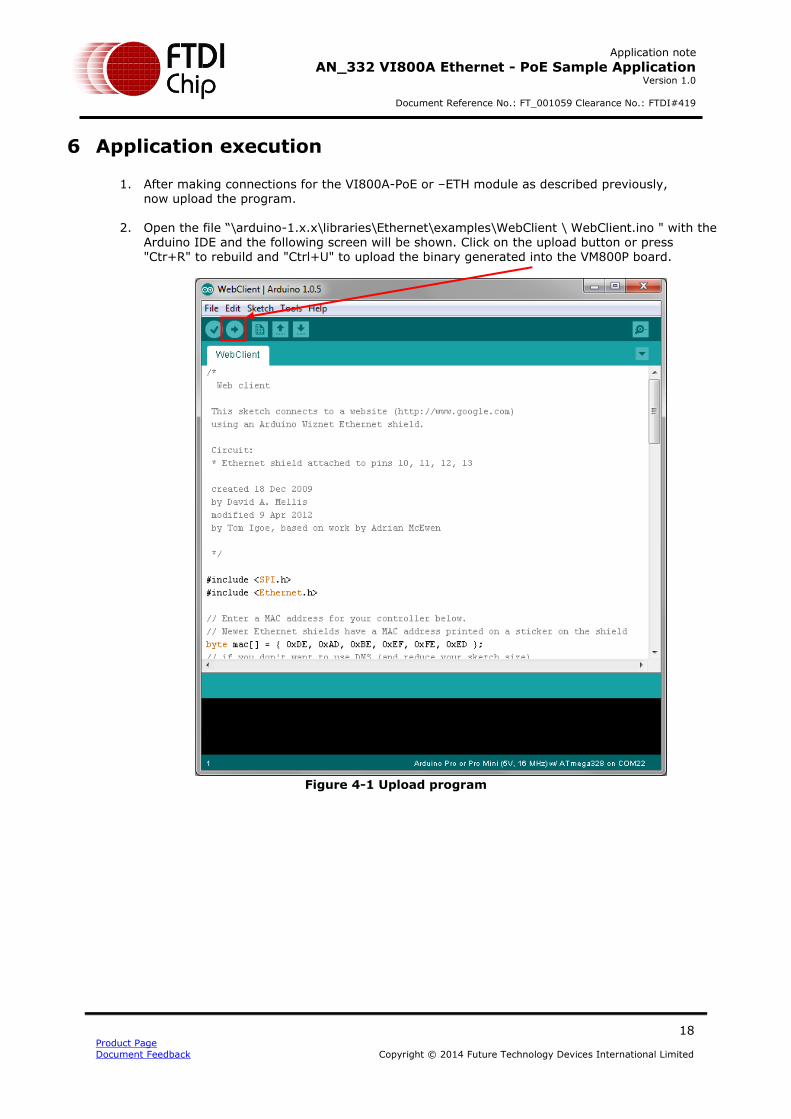
1. After making connections for the VI800A-PoE or –ETH module as described previously, now upload the program.
2. Open the file “\arduino-1.x.x\libraries\Ethernet\examples\WebClient \ WebClient.ino " with the Arduino IDE and the following screen will be shown. Click on the upload button or press "Ctr+R" to rebuild and "Ctrl+U" to upload the binary generated into the VM800P board.
Figure 4-1 Upload program
Application note
AN_332 VI800A Ethernet - PoE Sample Application Version 1.0
Document Reference No.: FT_001059 Clearance No.: FTDI#419
19 Product Page
Document Feedback Copyright © 2014 Future Technology Devices International Limited
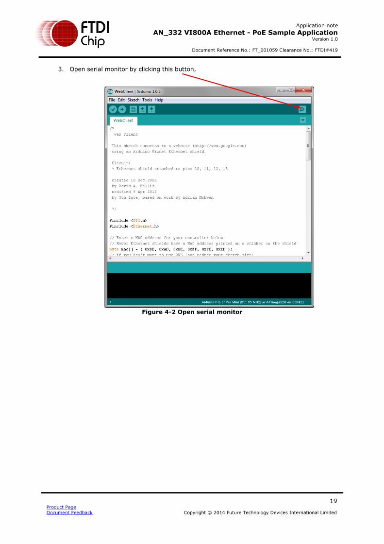
3. Open serial monitor by clicking this button,
Figure 4-2 Open serial monitor

Application note
AN_332 VI800A Ethernet - PoE Sample Application Version 1.0
Document Reference No.: FT_001059 Clearance No.: FTDI#419
20 Product Page
Document Feedback Copyright © 2014 Future Technology Devices International Limited
4. After opening the serial monitor, the following window will open, showing a connection has been made.
Figure 4-3 Serial monitor window showing Connection details
5. The sample code in combination with the API functions described previously can now be used to create applications where the VM800P has network access.

Application note
AN_332 VI800A Ethernet - PoE Sample Application Version 1.0
Document Reference No.: FT_001059 Clearance No.: FTDI#419
21 Product Page
Document Feedback Copyright © 2014 Future Technology Devices International Limited
7 Contact Information
Head Office – Glasgow, UK
Future Technology Devices International Limited Unit 1, 2 Seaward Place, Centurion Business Park Glasgow G41 1HH United Kingdom Tel: +44 (0) 141 429 2777 Fax: +44 (0) 141 429 2758 E-mail (Sales) [email protected]
E-mail (Support) [email protected]
E-mail (General Enquiries) [email protected]
Branch Office – Taipei, Taiwan
Future Technology Devices International Limited (Taiwan) 2F, No. 516, Sec. 1, NeiHu Road Taipei 114 Taiwan , R.O.C. Tel: +886 (0) 2 8791 3570 Fax: +886 (0) 2 8791 3576 E-mail (Sales) [email protected]
E-mail (Support) [email protected]
E-mail (General Enquiries) [email protected]
Branch Office – Tigard, Oregon, USA
Future Technology Devices International Limited (USA) 7130 SW Fir Loop Tigard, OR 97223-8160 USA Tel: +1 (503) 547 0988 Fax: +1 (503) 547 0987 E-Mail (Sales) [email protected]
E-Mail (Support) [email protected]
E-Mail (General Enquiries) [email protected]
Branch Office – Shanghai, China
Future Technology Devices International Limited (China) Room 1103, No. 666 West Huaihai Road, Shanghai, 200052 China Tel: +86 21 62351596 Fax: +86 21 62351595 E-mail (Sales) [email protected]
E-mail (Support) [email protected]
E-mail (General Enquiries) [email protected]
Web Site
http://ftdichip.com
Distributor and Sales Representatives
Please visit the Sales Network page of the FTDI Web site for the contact details of our distributor(s) and sales
representative(s) in your country.
System and equipment manufacturers and designers are responsible to ensure that their systems, and any Future Technology
Devices International Ltd (FTDI) devices incorporated in their systems, meet all applicable safety, regulatory and system-level
performance requirements. All application-related information in this document (including application descriptions, suggested
FTDI devices and other materials) is provided for reference only. While FTDI has taken care to assure it is accurate, this
information is subject to customer confirmation, and FTDI disclaims all liability for system designs and for any applications
assistance provided by FTDI. Use of FTDI devices in life support and/or safety applications is entirely at the user’s risk, and the
user agrees to defend, indemnify and hold harmless FTDI from any and all damages, claims, suits or expense resulting from
such use. This document is subject to change without notice. No freedom to use patents or other intellectual property rights is
implied by the publication of this document. Neither the whole nor any part of the information contained in, or the product
described in this document, may be adapted or reproduced in any material or electronic form without the prior written consent
of the copyright holder. Future Technology Devices International Ltd, Unit 1, 2 Seaward Place, Centurion Business Park,
Glasgow G41 1HH, United Kingdom. Scotland Registered Company Number: SC136640

Application note
AN_332 VI800A Ethernet - PoE Sample Application Version 1.0
Document Reference No.: FT_001059 Clearance No.: FTDI#419
22 Product Page
Document Feedback Copyright © 2014 Future Technology Devices International Limited
Appendix A– References
Document References
1. FT800 Datasheet
2. FT800 Programmers Guide 3. EVE Product Page
Acronyms and Abbreviations
Terms Description
Arduino Pro The open source platform variety based on ATMEL’s ATMEGA chipset
EVE Embedded Video Engine
SPI Serial Peripheral Interface
UI User Interface
USB Universal Serial Bus

Application note
AN_332 VI800A Ethernet - PoE Sample Application Version 1.0
Document Reference No.: FT_001059 Clearance No.: FTDI#419
23 Product Page
Document Feedback Copyright © 2014 Future Technology Devices International Limited
Appendix B – List of Figures
List of Figures
Figure 1-1 Block Diagram of Setup ............................................................................. 4
Figure 1-2 Architecture diagram ............................................................................... 5
Figure 2-1 VM800P Board ........................................................................................... 7
Figure 2-2 EB800-Ethernet Plug-In Module ................................................................ 8
Figure 2-3 POE connected to VM800P ........................................................................ 8
Figure 2-4 PoE Injector .............................................................................................. 9
Figure 2-5 LAN IN port and PWR connector ............................................................... 9
Figure 2-6 POWER+DATA OUT socket ........................................................................ 9
Figure 2-7 Power given to power injector ................................................................ 10
Figure 2-8 POWER+DATA OUT connection ............................................................... 10
Figure 2-9 LAN IN connection .................................................................................. 11
Figure 2-10 FXD LED ON ........................................................................................... 11
Figure 2-11 Complete Hardware setup for PoE ......................................................... 12
Figure 3-1 Flowchart ................................................................................................ 17
Figure 4-1 Upload program ...................................................................................... 18
Figure 4-2 Open serial monitor ................................................................................ 19
Figure 4-3 Serial monitor window showing Connection details ................................ 20

Application note
AN_332 VI800A Ethernet - PoE Sample Application Version 1.0
Document Reference No.: FT_001059 Clearance No.: FTDI#419
24 Product Page
Document Feedback Copyright © 2014 Future Technology Devices International Limited
Appendix C – Revision History
Document Title: AN_332 VI800A Ethernet - PoE Sample Application
Document Reference No.: FT_001071
Clearance No.: FTDI#419
Product Page: http://www.ftdichip.com/EVE.htm
Document Feedback: Send Feedback
Revision Changes Date
1.0 Initial release 2014-10-23
Top Related