


Languages
Pages
Legal


UNIVERSITI TEKNIKAL MALAYSIA MELAKA
DEVELOPMENT OF MINI CNC MILLING MACHINE FOR
SMALL SCALE PRODUCTION
This report submitted in accordance with requirement of the Universiti Teknikal
Malaysia Melaka (UTeM) for the Bachelor Degree of Manufacturing Engineering
(Manufacturing Process)(Hons.)
by
MOHD. NAJIB BIN ZAMRI
B051010220
870706-23-5119
FACULTY OF MANUFACTURING ENGINEERING
2014
UNIVERSITI TEKNIKAL MALAYSIA MELAKA
BORANG PENGESAHAN STATUS LAPORAN PROJEK SARJANA MUDA
TAJUK: Development of Mini CNC Milling Machine for Small Scale Production
SESI PENGAJIAN: 2013/14 Semester 2 Saya MOHD. NAJIB BIN ZAMRI mengaku membenarkan Laporan PSM ini disimpan di Perpustakaan Universiti Teknikal Malaysia Melaka (UTeM) dengan syarat-syarat kegunaan seperti berikut:
1. Laporan PSM adalah hak milik Universiti Teknikal Malaysia Melaka dan penulis. 2. Perpustakaan Universiti Teknikal Malaysia Melaka dibenarkan membuat salinan
untuk tujuan pengajian sahaja dengan izin penulis. 3. Perpustakaan dibenarkan membuat salinan laporan PSM ini sebagai bahan
pertukaran antara institusi pengajian tinggi.
4. **Sila tandakan ( )
SULIT
TERHAD
TIDAK TERHAD
(Mengandungi maklumat yang berdarjah keselamatan atau kepentingan Malaysia sebagaimana yang termaktub dalam AKTA RAHSIA RASMI 1972)
(Mengandungi maklumat TERHAD yang telah ditentukan oleh organisasi/badan di mana penyelidikan dijalankan)
Alamat Tetap:
Kampung Parit Bakar,
Jalan Abdul Rahman,
Muar, Johor Darul Takzim
Tarikh:
Disahkan oleh:
Cop Rasmi: Tarikh: _______________________
** Jika Laporan PSM ini SULIT atau TERHAD, sila lampirkan surat daripada pihak berkuasa/organisasi berkenaan dengan menyatakan sekali sebab dan tempoh laporan PSM ini perlu dikelaskan sebagai SULIT atau TERHAD.

DECLARATION
I hereby, declared this report entitled “Development of Mini CNC Milling Machine
for Small Scale Production” is the results of my own research except as cited in
references.
Signature :
Author’s Name : Mohd. Najib Bin Zamri
Date :

APPROVAL
This report is submitted to the Faculty of Manufacturing Engineering of UTeM
as a partial fulfillment of the requirements for the degree of Bachelor of
Manufacturing Engineering (Manufacturing Process) (Hons.). The member of
the supervisory is as follow:
………………………………
(Project Supervisor)
APPROVAL
This report is submitted to the Faculty of Manufacturing Engineering of
UTeM as a partial fulfillment of the requirements for the degree of Bachelor
of Manufacturing Engineering (Manufacturing Process) (Hons.). The
members of the supervisory committee are as follow:
………………………………
(Principal Supervisor)
………………………………
(Co-Supervisor)

i
ABSTRACT
This thesis contains the report of how to build the mini CNC milling machine with
the low cost compared to other machine that usually used in industry. This machine
will be tested in term of accuracy and performance by doing some experiments. Most
of the material that used to build this machine is Aluminum 6020 Alloy. Computer
Numerical Control (CNC) machining is a process used in the manufacturing sector
that involves the use of computers to control machine tools without direct human
assistance. Tools that can be controlled in this manner include lathes, mills, routers,
and grinders. CNC is a very broad term that encompasses a variety of types of
machines all with different sizes, shapes, and functions. In modern CNC systems,
mostly component design is highly automated using Computer Aided Design (CAM)
programs but for this mini CNC milling machine, it is a simple and use basic CNC
machine operation by usingMach3 software. There have some part that uses such as
water cooled spindle with power 2.2 kilowatt, ball screw bearing, stepper motor,
bearing, rail bearing, and some electronics parts. Some machining process are
involves such as drilling, milling, cutting, facing, and others. This study focuses
more on the how to build a mini CNC milling machine where this machine are very
own, fully functional, easy to maintain and inexpensive. This machine also can cut,
carves, engraves and drills any material depends on machine specifications that are
build.
ii
ABSTRAK
Tesis ini mengandungi laporan bagaimana untuk membina mesin kecil CNC dengan
kos yang rendah berbanding dengan mesin CNC yang sediada yang biasanya
digunakan dalam industri. Mesin ini akan diuji dari segi ketepatan dan prestasi
dengan melakukan beberapa eksperimen. Kebanyakan bahan yang digunakan untuk
membina mesin ini adalah Aluminium Alloy 6020 . Kawalan Berangka Komputer (
CNC) pemesinan adalah satu proses yang digunakan dalam sektor pembuatan yang
melibatkan penggunaan komputer untuk mengawal peralatan mesin tanpa bantuan
manusia secara langsung . Alat-alat yang boleh dikawal dengan cara ini termasuk
mesin larik, router, dan pengisar . CNC adalah satu istilah yang sangat luas yang
merangkumi pelbagai jenis mesin dengan saiz yang berbeza , bentuk dan fungsi.
Dalam sistem CNC moden, reka bentuk kebanyakannya automatik dengan
menggunakan program Rekabentuk Berbantukan Komputer (CAM) tetapi untuk
mesin CNC kecil ini , ia adalah satu asas mesin operasi CNC mudah digunakan oleh
perisian Mach3 . Terdapat beberapa bahagian yang menggunakan seperti ‘spindle
motor’ dengan kuasa 2.2 kilowatt , ‘ball crew bearing’, ‘stepper motor’ , ‘bearing’,
‘linear rail bearing, dan beberapa bahagian elektronik. Terdapat beberapa proses
pemesinan yang terlibat seperti penggerudian ,memotong, dan lain-lain . Kajian ini
lebih tertumpu kepada bagaimana untuk membina sebuah mesin CNC di mana mesin
ini boleh berfungsi sepenuhnya , mudah untuk digunakan dan murah. Mesin ini juga
boleh memotong dan mengukir pelbagai jenis bahan bergantung kepada spesifikasi
mesin yang membina.

iii
DEDICATION
To my beloved parents

iv
ACKNOWLEDGEMENT
I would like to thank to my highest appreciation to my supportive academic
supervisor, Mr.Hadzley Bin Abu Bakar. His supervision and support that gave me
truly helps during the period of conducting my thesis. His never-ending supply of
valuable advice and guidance has enlightens me and deeply engraved in my mind.
Next, I would like to dedicate my thankfulness to the helpful of Mr. Shahir Bin
Kasim, as my second supervisor for his enthusiastic support and supervision of the
thesis revision. I’m also happy to present my gratefully acknowledge to Machinery
laboratory technicians, who has been so warmth and kind to provide sincere
assistance and good cooperation during the training. I’m also would like to convey
thanks to FKP lecturers for their assistance which really spend their time to teach me
a lots of knowledge regarding to the design development.
Last but not least, I would like to state my appreciation to staff – Faculty of
Manufacturing Engineering, FKP, my friends and colleagues for supporting me and
administration department for their help in the project. Thank you.
v
TABLE OF CONTENT
Abstrak i
Abstract ii
Dedication iii
Acknowledgement iv
Table of Content v
List of Tables vi
List of Figures vii
List Abbreviations, Symbols and Nomenclatures viii
CHAPTER 1: INTRODUCTION 1
1.1 Background 3
1.2 Objective 3
1.3 Scope of Project 3
CHAPTER 2: LITERATURE REVIEW 4
2.1 Machining 4
2.1.1 Element of Machining 5
2.1.2 Classical of Machining Process 5
2.1.3 Areas of Deformation 6
2.1.4 Cutting Parameters 7
2.1.5 Depth of Cut 8
2.2 CNC Machine 9
2.3 Advantages and Disadvantages of CNC 10
2.4 Types of CNC Machine 11
2.4.1 Lath CNC Machine 11
2.4.2 Milling CNC Machine 11
2.5 Materials of Choice 12
2.6 Major Components of Mini CNC Machine 13

vi
2.6.1 Gantry Sides 13
2.6.2 Table (worktable) 14
2.6.3 Spindle 14
2.6.4 Stepper Motor 14
2.6.5 Ball Screw Bearing 15
2.6.6 Stepper Motor Driver 15
CHAPTER 3: METHODOLOGY 16
3.1 Introduction 16
3.2 Overall of Methodology 18
3.2.1 Design Concept 19
3.2.2 Design for Assembly 22
3.2.3 Selection Process 22
3.2.4 Best Design Concept 22
3.2.5 Design for Fabricated 22
3.2.6 Prototype 22
3.2.7 Suggestion for Simplification of Product 23
3.2.8 Identification Process 23
3.2.9 Detail Design for Minimum Fabrication Cost 23
3.2.10 Production or Development 23
3.3 Pugh Method 23
3.3.1 Pugh Selection Method of CNC Machine 25
3.4 Final Concept Selected 26
3.5 Material Selection for the CNC Machine 26
3.6 Fabrication Process Selection 26
3.7 Preparing the Equipment and Instrument 28
3.7.1 Vernier Caliper 28
3.7.2 Ruler 29
3.7.3 Measuring Tape 29
3.7.4 Sandpaper 30
3.8 Preparing Machine and Tool Specification 30
3.8.1 Lathe Machine 30
vii
3.8.2 Bandsaw 31
3.3.3 Drilling Machine 32
3.9 Material Preparation 32
3.10 Fabrication Process Selection 34
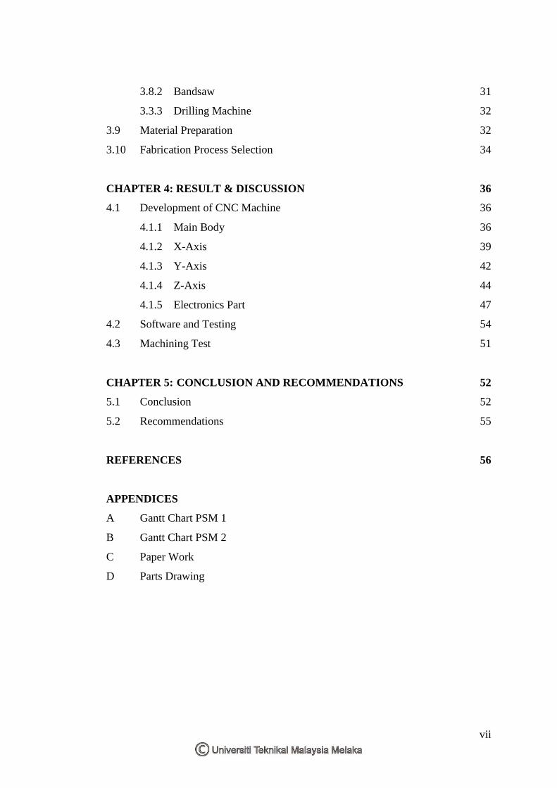
CHAPTER 4: RESULT & DISCUSSION 36
4.1 Development of CNC Machine 36
4.1.1 Main Body 36
4.1.2 X-Axis 39
4.1.3 Y-Axis 42
4.1.4 Z-Axis 44
4.1.5 Electronics Part 47
4.2 Software and Testing 54
4.3 Machining Test 51
CHAPTER 5: CONCLUSION AND RECOMMENDATIONS 52
5.1 Conclusion 52
5.2 Recommendations 55
REFERENCES 56
APPENDICES
A Gantt Chart PSM 1
B Gantt Chart PSM 2
C Paper Work
D Parts Drawing
vii
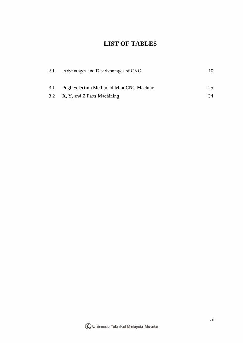
LIST OF TABLES
2.1 Advantages and Disadvantages of CNC 10
3.1 Pugh Selection Method of Mini CNC Machine 25
3.2 X, Y, and Z Parts Machining 34

viii
LIST OF FIGURES
2.1 Deformation of material in machining
2.2 (a) Orthogonal cutting (b) Oblique cutting
2.3 Deformation zones during machining
2.4 Basic machining operation and important parameters
2.5 3-Axis CNC Milling Machine
2.6 Mini CNC Milling Machine 3-Axis
2.7 Ball Screw
2.8 3 Axis Stepper Motor Controller
3.1 Flow Chart
3.2 Design of Mini CNC Machine steps
3.3 Design 1
3.4 Design 2
3.5 Design 3
3.6 Fabrication Flow Process
3.7 Vernier Caliper
3.8 Ruler
3.9 Measuring Tape
3.10 Sandpaper
3.11 Lathe Machine
3.12 Bandsaw Machine
3.13 Drilling Machine
3.14 Aluminum 6020 Alloy
3.15 Measuring Process
3.16 Aluminum 6020 Alloy Cutting
4.1 Base Frame and Gantry Sides Assembled Model
4.2 Aluminum 6020 Alloy Cutting

ix
4.3 Drilling some hole through on the base frame and gantry sides
4.4 Base Frame and Gantry Sides Assemblies
4.5 X-Axis All Parts Assembled Model
4.6 Part A Assembled
4.7 Part A and Part B Assembled
4.8 X-Axis Parts Assembled Model
4.9 Part C Assembled
4.10 Y-Axis All Parts Assembled Model
4.11 Part D and Part E Assembled
4.12 Some standard parts uses in y-axis
4.13 Z-Axis All Parts Assembled Model
4.14 Part F, G, and H Assembled
4.15 Linear bearing is installed on the top of bars
4.16 Standard Parts Model
4.17 Part H and Part I Assembled
4.18 Stepper motor with wire bundle
4.19 One stepper driver is required for each stepper motor
4.20 The breakout board connected to computer
4.21 The power supply that provides the proper voltage
4.22 The main screen of Mach3
4.23a Cutting process on mild steel material using different machine:
3-axis mini milling machine
4.23b Cutting process on mild steel material using different machine:
existing machine
5.1 Maximum and minimum movement for each Axis.
5.2 Measurements of dimensions A and B after machining process
x
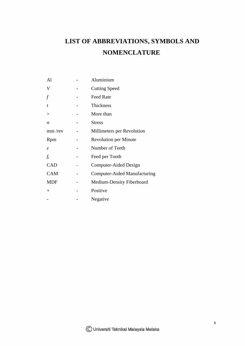
LIST OF ABBREVIATIONS, SYMBOLS AND
NOMENCLATURE
Al - Aluminium
V - Cutting Speed
f - Feed Rate
t - Thickness
> - More than
σ - Stress
mm /rev - Millimeters per Revolution
Rpm - Revolution per Minute
z - Number of Teeth
ft - Feed per Tooth
CAD - Computer-Aided Design
CAM - Computer-Aided Manufacturing
MDF - Medium-Density Fiberboard
+ - Positive
- - Negative

1
1.1 Background
Machining is a chip removal process from raw material where the material is cut into
a desired final shape and size by using a various processes with specific machine.
Machining is used because it has a high accuracy. By machining, the time to produce
a parts or product will decrease and production will rise higher. Machining has
evolved over the past two centuries as technology has advanced in term of the
precise which are traditional or conventional machining and non-traditional machine
or advanced machining.
Traditional machining processes such as milling, turning, drilling, boring, sawing,
tapping, broaching, and planning. In these traditional machining processes included
milling, turning, lathes machines, drill presses or others are used a sharp cutting tool
to remove material to achieve a desired final size and shape of the parts or products.
For non-traditional machining processes, it is used chemical, thermal, or electrical
processes to machine a workpiece such as electrical discharge, electrochemical
machining, electron beam machining, and ultrasonic machining. These advanced
machining includes a wide range of operation used for special purpose or special
workpiece.
Now, a used machine is in automated form which is controlled by a computer
program called Computer Numerical Control (CNC). CNC is a command-based
coordinate to get a form for you automatically [(Kalpakjian 2006)].
INTRODUCTION
CHAPTER 1
CHAPTER 1

2
In the 1940s, CNC machines were first built and were programmed by using paper
tape with holes punched into it at specific points. After that, these early systems were
changed with the augmentation of analogue and digital computers. To improve the
productivity of the machine and the quality of the work, the range of CNC systems
were be fitted to previously manually operate machine tools, and these systems
provide a selection of features which can significantly.
Computer numerical control (CNC) machining is a process used in the
manufacturing sector that involves the use of computers to control machine tools
such as lathes, mills, turning, grinders, and others without direct human assistance.
The use of a CNC machines are widely where that includes a variety of types of
machines in different function, designs, and sizes. But the main point of a CNC is to
simply understand that it is all about using a computer where the codes will control a
machine that carves useful object from raw material to be a products or parts. For
example, a CNC machine might begin with a solid block of Aluminum 6020 Alloy
then the cutting tools from the machine will remove away the material to make a
parts or products such as a gear shaft. In modern CNC systems, component design is
highly automated using Computer Aided Design (CAD) and Computer-Aided
Manufacturing (CAM) programs.
There are two types of CNC machines which are turning machine and milling
machine. A turning machine is generally made up of a device that rotates a
workpiece at high speed then the cutting tool will removes off the undesired material
from the workpiece until achieves the desired form that needed. For a milling
machine, various directions of rotating and cutting can be done by special tools.
These special tool can moves in three directions axis which is x, y, and z-axis.
Mostly, all manufacturing industry uses CNC machine to produce a product in large
quantities because it is no efficient or profitable to make everyday product by hand.
By using CNC machine it is possible to produce hundreds or even thousands of the
same products in a day. First, the design engineer will draw the product based on
customer requirement using design software such as Computer Aided Design (CAD)
and Computer-Aided Manufacturing (CAM) programs, than it is process by
3
computer and manufactured using the CNC machine. In industry, CNC machine can
be extremely large.
1.2 Objective
There are three main objectives by doing this project:
Identify the parts of the CNC milling machine to build the mini milling CNC
machine.
To build mini CNC milling machine by assembled all the parts with some
guided.
Test the mini CNC milling machine which has been builds with some
experiment.
1.3 Scope of Project
This project will be focus more on the how to build a mini CNC Milling machine
where this machine are very own, fully functional, easy to maintain and inexpensive.
It also can cuts, carves, engraves and drills any material depends on machine
specifications that were building. On these project each parts that used to build the
machine will assemble together to becomes a complete mini CNC milling machine.
After that, this machine will tested with some experiment to look the machine
accuracy and running condition. By refer to the result experiment, we will know
either this mini CNC milling machine in a good condition or not. Some modification
or adjustment will make if the machine has a problem.
4
2.1 Machining
Machining is characterized by an operation of a cutting tool that engages a workpiece
to remove a layer of material in the form of a chip [Shneider (2007)]. As the cutting
tool engages the workpice, the material ahead of the tool is sheared and deformed
under enormous pressure. The deformed material then seeks to relieve its stressed
condition by separating and flowing into the air in the form of a chip. This operation
involves large plastic deformations accompanied by elastic, thermal, and frictional
effects in a region enclosed by the workpiece, the chip and the cutting tool [Childs
(2000)].
Machining is usually divided into the following categories:
Cutting which generally involves single-point or multipoint cutting tools, each
with a clearly defined tool shape;
Abrasive processes such as grinding;
Advanced machining processes that utilize electrical, chemical, thermal, and
hydrodynamic methods as well as lasers.
LITERATURE REVIEW
CHAPTER 2
5
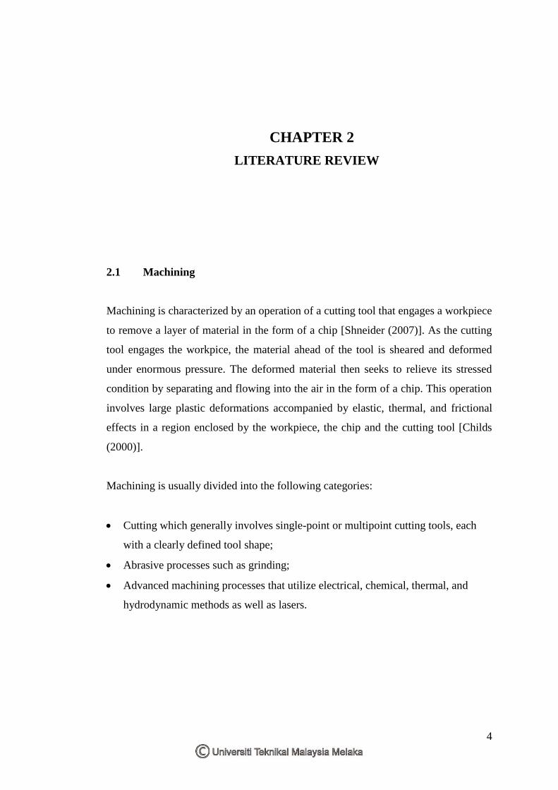
2.1.1 Elements of Machining
Figure 2.1 shows a schematic illustration to represent the nomenclature of the
machining process. The undeformed chip thickness, t1, is the value of the depth of
cut while, t2, is the thickness of the deformed chip after leaving the workpiece. The
major deformation starts when the cutting tool, in a rake angle, α, shears the metal to
form an angle of shear, Ø, at a specific cutting speed, V, and feed rate, f. The
deformed chip is separated from the parent material by fracture to remove the excess
stock of the parent material to create a finished workpiece of the required dimensions
[Shneider (2007)].
Figure 2.1: Deformation of material in machining [Kalpakjian (2000)].
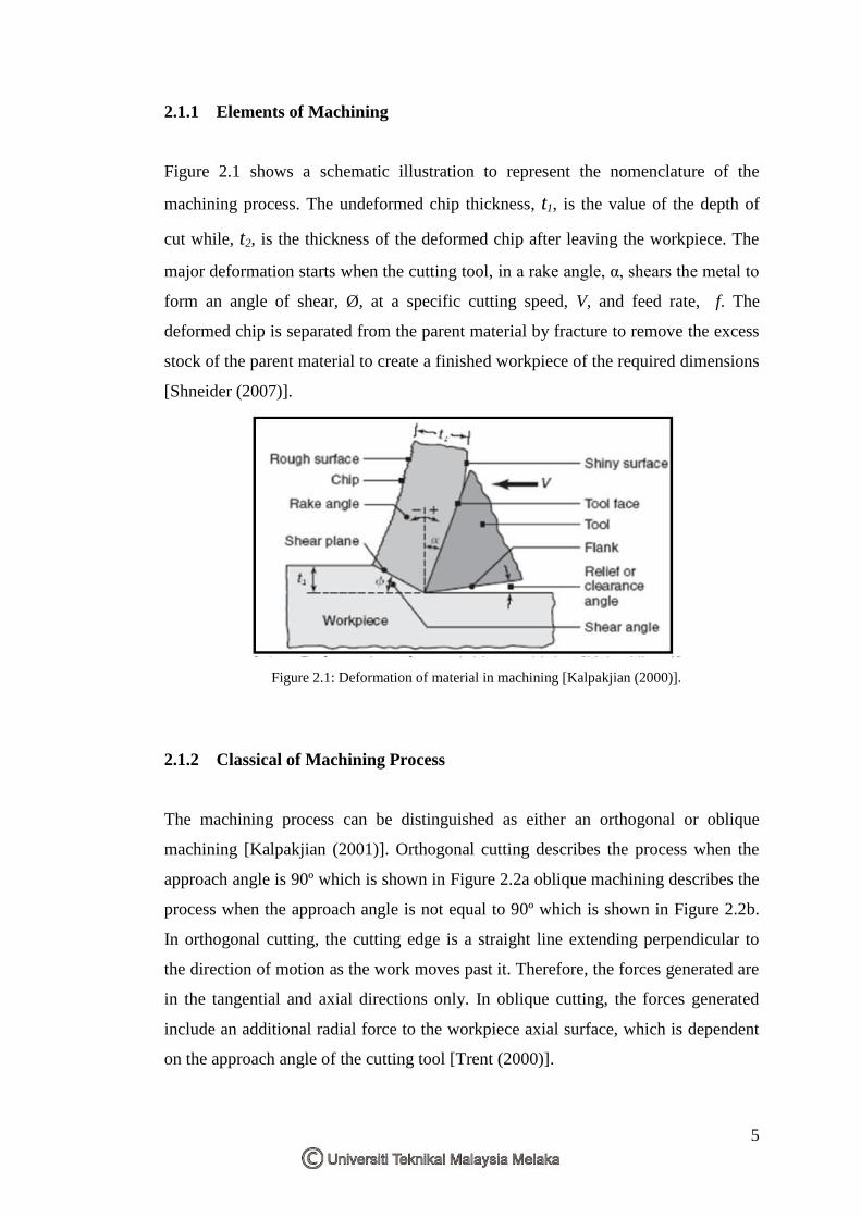
2.1.2 Classical of Machining Process
The machining process can be distinguished as either an orthogonal or oblique
machining [Kalpakjian (2001)]. Orthogonal cutting describes the process when the
approach angle is 90º which is shown in Figure 2.2a oblique machining describes the
process when the approach angle is not equal to 90º which is shown in Figure 2.2b.
In orthogonal cutting, the cutting edge is a straight line extending perpendicular to
the direction of motion as the work moves past it. Therefore, the forces generated are
in the tangential and axial directions only. In oblique cutting, the forces generated
include an additional radial force to the workpiece axial surface, which is dependent
on the approach angle of the cutting tool [Trent (2000)].
6
(a) (b)
Figure 2.2: (a) Orthogonal cutting (b) Oblique cutting [Schneider (2000)]
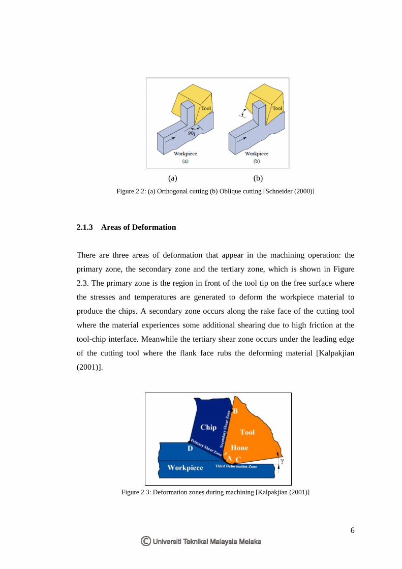
2.1.3 Areas of Deformation
There are three areas of deformation that appear in the machining operation: the
primary zone, the secondary zone and the tertiary zone, which is shown in Figure
2.3. The primary zone is the region in front of the tool tip on the free surface where
the stresses and temperatures are generated to deform the workpiece material to
produce the chips. A secondary zone occurs along the rake face of the cutting tool
where the material experiences some additional shearing due to high friction at the
tool-chip interface. Meanwhile the tertiary shear zone occurs under the leading edge
of the cutting tool where the flank face rubs the deforming material [Kalpakjian
(2001)].
Figure 2.3: Deformation zones during machining [Kalpakjian (2001)]
7
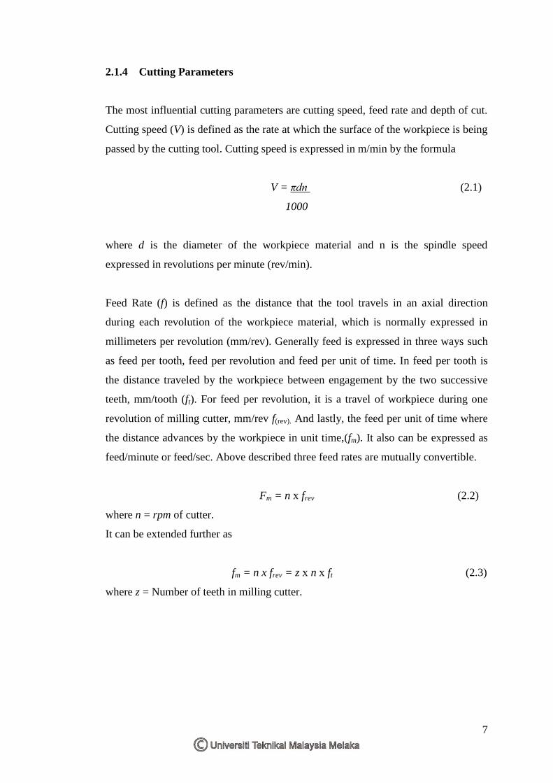
2.1.4 Cutting Parameters
The most influential cutting parameters are cutting speed, feed rate and depth of cut.
Cutting speed (V) is defined as the rate at which the surface of the workpiece is being
passed by the cutting tool. Cutting speed is expressed in m/min by the formula
V = πdn (2.1)
1000
where d is the diameter of the workpiece material and n is the spindle speed
expressed in revolutions per minute (rev/min).
Feed Rate (f) is defined as the distance that the tool travels in an axial direction
during each revolution of the workpiece material, which is normally expressed in
millimeters per revolution (mm/rev). Generally feed is expressed in three ways such
as feed per tooth, feed per revolution and feed per unit of time. In feed per tooth is
the distance traveled by the workpiece between engagement by the two successive
teeth, mm/tooth (ft). For feed per revolution, it is a travel of workpiece during one
revolution of milling cutter, mm/rev f(rev). And lastly, the feed per unit of time where
the distance advances by the workpiece in unit time,(fm). It also can be expressed as
feed/minute or feed/sec. Above described three feed rates are mutually convertible.
Fm = n x frev (2.2)
where n = rpm of cutter.
It can be extended further as
fm = n x frev = z x n x ft (2.3)
where z = Number of teeth in milling cutter.

8
2.1.5 Depth of Cut
Depth of cut in milling operation is the measure of penetration of cutter into the
workpiece. It is thickness of the material removed in one pairs of cutter under
process. One pairs of cutter means when cutter completes the milling operation from
one end of the workpiece to another end. In other words, it is the perpendicular
distance measured between the original and final surface of workpiece. Figure 2.4
shows the important parameters for the basic machining operation.
Figure 2.4: Basic machining operation and important parameters
[Kalpakjian (2001)].
Top Related