


Languages
Pages
Legal


TRIKE WING “PROFI TL”
MANUAL
Size: ____________
Manufactured by: AEROS Ltd. Tel: (380 44) 455 41 18, Post-Volynskaya St. 5 Fax: (380 44) 455 41 16 Kiev 03061 E-mail: [email protected], UKRAINE http://www.aeros.com.ua Date of production: ____________________
Serial number: _______________________

2
1
Table of Contents
Sect ion 1. General Information_____________________________________________________3
1.1. Introduction__________________________________________________________________________3 1.2. Main Data___________________________________________________________________________3
1.3. Safety instructions_______________________________________________________3
Sect ion 2. Set Up Procedure________________________________________________________5
2.1. Set Up Procedure From The Package 4 Meters Long __________________________________5 2.2. Set Up Procedure From The Package 6 Meters Long __________________________________9 2.3. Profi TL breakdown______________________________________________________19
Sect ion 3. Prefl ight Inspection Of The Wing ___________________________________20
3.1. Beginning At The Nose______________________________________________________________20 3.2. Along The Left Leading Edge ________________________________________________________21 3.3. At The Left Wingtip__________________________________________________________________21 3.4. Along The Trailing Edge, Left Wing __________________________________________________21 3.5. From The Rear Keel________________________________________________________________21 3.6. Along The Trailing Edge, Right Wing ________________________________________________22 3.7. At The Right Tip____________________________________________________________________22
3.8. Along The Right Leading Edge _____________________________________________________ 22 3.9. Under The Wing At The Control Bar _________________________________________________22 3.10. Fit The Nose Cone_________________________________________________________________22
Section 4. Sail Removal______________________________________________________23
Sect ion 5. Inspection Of The Wing ________________________________________________28
5.1. Sail Check-Up______________________________________________________________________28 5.2. Cable System_______________________________________________________________________28 5.3. Checking The Tubings______________________________________________________________29 5.4. Checking The Battens_______________________________________________________________29 5.5. Fasteners___________________________________________________________________________29
Sect ion 6. Maintenance_____________________________________________________________30
6.1. Wing Tuning_________________________________________________________________________30 6.1.1. Cg Adjustment___________________________________________________________________30 6.1.2. Turn Trim________________________________________________________________________30 6.2. Maintenance________________________________________________________________________31 6.3. Storage_____________________________________________________________________________31 6.4. Transportation______________________________________________________________________31
In Closing – A Few Final Words On Your Safety _______________________________32
Log Book_______________________________________________________________________________33
Schemes_______________________________________________________________________________34

3
Section 1. GENERAL INFORMATION 1.1. I N T R O D U C T I O N Thank you for purchasing an Aeros wing. Welcome to the PROFI TL, the new innovative non-kingposted wing for two-seater trikes - is a product of Aeros Ltd. It is the result of an extensive design and development program aimed at optimizing your level of safety and satisfaction as a pilot, through their high performance and strength of construction. The PROFI TL was designed for the experienced pilots, never for beginners. PROFI TL will provide you with fast cruising speed. Easy storing in an airplane hangar will save your time by removing the need to disassemble. This wing is safely controllable and stable at a wide range of operating speeds but your trike should be properly adapted to fly with speedy Profi TL. The strength of the wing is sufficient for different conditions of flight with defined load. Please read and be sure you thoroughly understand this manual before flying your PROFI TL. Be sure you are thoroughly familiar with set up, break down, preflight and maintenance procedures as described in this manual. Please read thoroughly the SAFETY INSTRUCTIONS. Be sure your Profi TL wing is properly adapted to your trike as well as your trike is adapted to use with Profi TL wing. Aeros recommend this wing only to be used if trike has the wheel fairings with fins. A thorough test flight must be performed by a highly qualified test pilot before you fly your microlight. Please visit us regularly Aeros WEB site: http://www.aeros.com.ua Having any doubts or questions contact us by e-mail: [email protected] We wish you a safe and enjoyable flying career. Aeros Ltd. 1.2. M A I N D A T A
PROFI TL is a high performance flexible wing for a double seater trike. Wing type PROFI TL 14 PROFI TL 12 Sail area, sqm 14.5 12.5 Wing span, m 10.0 9.3 Aspect ratio 6.9 6.9 Nose angle, deg 128 128 Max airspeed, kmph 140+ 150+ Stall speed, kmph (with max load) 52 60 Speed of max glide angle, kmph (with max load) 70 80 Range of operating overloads Ultimate tested strength, G
+4/-2 +6/-3
+4/-2 +6/-3
Total load max, kg 450 450 Weight without bag, kg 60.0 57
1.3. S A F E T Y I N S T R U C T I O N S * PROFI TL was not designed to fly at bank angle over 60 degrees or pitch angle exceeding 30 degrees. Operation in any of these modes may severely compromise your safety.

4
* The flying of any trike in presence of turbulence or gusty wind can result in flight inversion, structural failure of the wing and possible fatal injuries.
* Performance of the wings with trilam leading edge can worsen in wet (rain, thick fog, dew, etc.) and ice-covering conditions, therefore we do not recommend to use wings in such conditions, as this can compromise your safety. * The PROFI TL range of speeds and wing handling really impress and exceed all expectations…A microlight with this wing accelerates within seconds easily and fast; any increase in engine power affects directly the speed, not so much the climb rate. This creates possibilities and qualities for the trike, which the trike pilots in the past only could dream about. But! Here are simple and definite dangers: 1) The easy and dynamic acceleration of a trike with the Profi TL wing requires from a pilot adaptation to a changed handling. The pilot must be experienced enough and with good flying abilities on trikes to understand the new requirements. 2) During the flight tests we found out that it may be a problem, if the trike Aeros 2-912, Profi TL has no wheel fairings with fins. In that case the trike tends to progressively turn left when it is flying faster then 110km/h. The progressive dynamic of such turns definitely startled Aeros test pilots and made them find out, that limits could be reached which are beyond controllability. The reasons of this effect we found to be the following: - powerful engines enable trikes to fly at higher speed, on the other hand they (with the large and heavy propellers) create a much larger moment around the longitudinal axis which moves (in case with the Rotax 912) the trike to the left (relative to the wing axis) with trike nose turning to the right. On the high speed (and high engine RPM) the right wing begins to slip with lift increasing, in result the trike will turn to the left; -large, heavy multiblade propeller on high RPM works as gyroscope . So, during abrupt high speed turn the trike could not follow the wing trajectory(outer wing will slip) and, because of gyroscopic precession, could change the pitch angle. In this case the bank of the turn will increase violently; -trike fairing with large lateral surface, especially in the nose part, create a strong destabilizing moment when it slips. All these phenomena can be counteracted by fixing a stabilizing fins far enough behind the center of gravity of the trike body ,or by increasing, concentrating the lateral surface on the rear part of the trike ( like trike without fairing has), or by winglets(with fins) mounting on the wing . No such effects were observed when flying Profi TL with trike Aeros 1-582. This trike has the same accelerating and of course it requires from pilot adequate handling responses. But there are no dangerous regimes that are near the limit of controllability, which exist when flying the Aeros 2-912 Profi TL without the wheel fairings with the fins. These observations in our mind the following requirements must be adhered when using the PROFI TL wing: 1. Using the Profi TL wing on the other trikes then the AEROS trikes require adapting of the hang point, height of the control frame, position of the control bar in flight and checking of sufficient clearance of any part of the wing to the propeller in any position possible to steer. These checks usually are done without mentioning. In case of the PROFI TL wing your trike has to be also adapted for Profi TL wing and a thorough test flight must be performed in which a highly qualified test pilot must check the microlight has no effect as described above. 2. It is clear that on trikes, which have large fairings, such as Aeros 2, Cobra, Class…, applying the Profi TL wing not acceptable, if flying without the wheel fairings with fins. Even with wheel fairings with fins, when using the Profi TL wing test flights by proficient pilots are without exception required to prove save handling in any situation.

3. The probability of observing such effects with trikes like Antares (Graffitti) and similar is much lower. But they too are required to perform thorough flight test by qualified test pilot. 4. There were no such effects observed while using any trike with the standard PROFI with kingpost. When ordering the PROFI TL You must consider all these aspects. In case You are not absolutely sure about Your choice please also consider the following: - change the order from Profi TL to Profi. - send to Aeros all information (picture, trike and engine characteristics) about the trike, on which the Profi TL is supposed to be installed, for discussion and analyzing the installation. …and if nothing can satisfy You completely, than - cancel the order. Without question You will be reimbursed for any prepayment You have made.
Section 2. SET UP and BREAKDOWN PROCEDUREs 2.1. SET UP PROCEDURE FROM THE PACKAGE 4 METRES LONG Having used the specific techniques described in this manual you will perform the set up and break down procedures without any difficulties. However, the following procedural descriptions are not intended to be a substitute for the familiarization procedure of your dealer at the time the wing is delivered. The set up procedure should be carried out on a clean, not abrasive surface. Before performing the set up procedure you must place the glider nose to the wind. During this procedure you must make a preflight inspection of the wing. 2.1.1. With the glider in the bag (4 meters long) lay the glider on the ground. 2.1.2. Undo the zipper. Untie the Velcro straps. Remove supports, the battens, the control bar and the leading edge tubes N3 from the bag. 2.1.3. Turn the glider so that the downtubes packed into the safety bags are on the bottom. 2.1.4. Unfold the sail along the leading edge (Fig. 1).
a b Fig. 1
5

2.1.5. Attach the leading edge tubes N3 to the leading edge tubes N2 according to the marking (L-left, R-right, marks must be on the top) (Fig. 2). If the wing equipped with the winglets-remove the special pins from the LE N3 tube ends, for easier sail tips mounting.
a
b
Fig. 2
6

While installing the leading edge tubes into the sail, place the washout struts facing forward toward the nose of the wing and along the leading edge tubes (Fig. 3). Put washout tips outside of the sail through the access zippers. Make sure that the leading edge tube #3 is properly installed.
Fig. 3
2.1.6. Tighten the sail along the leading edge and mount it to the rear leading edge, make sure to align the sail mount webbing squarely in the slot and attach the securing velcros (Fig. 4). The sail is mounted to the leading edge by the inner (forward) of the two loops of webbing. The outer loop is a pull handle only.
a b Fig. 4
2.1.7. If the keel and #1 battens don’t installed in the sail, it’s necessary to make this. Remove the battens from the batten bag and install the #1 battens to the wing. Next step is to install the keel battens (Fig. 5 and 6) Aeros convention is that red marked battens go in the left wing and green marked battens in the right. Battens are numbered from the center outwards and the longest batten in a PROFI TL is marked as the "# 1" batten.
7

Fig. 5
Fig. 6
2.1.8. Spread the wings all the way. Pay attention to the nose bottom part of the sail, it has to be located between the keel tube and nose channel! Attach the shackle of the sweep wire to the hook, which is placed on the keel tube. Install the tangs on the nose of the sail over the bolt and secure with a nut (Fig. 7).
Fig. 7
8

Through the holes in the sail tips –attach the special pins for the winglets mounting.
9
.2. SET UP PROCEDURE FROM THE PACKAGE 6 METRES LONG
.2.1. With the glider in the bag (6 meters long) lay the glider on the ground (Fig. 8). Choose
(Fig.7a) 2.1.9. Release the sweep wire from the hook on the keel tube to loose a tension of the sail. 2.1.10. The further set up procedure is similar the one from a 6-meter long bag (Section 2.2, except points 2.2.1-2.2.4). Fig.7a
2 2the most possibly flat spot for rigging.
Fig. 8 2.2.2. Undo the zipper. Remove the battens, the struts and the control bar from the bag.
.2.4. Remove the control
ne side
ng
2.2.3. Untie the two central velcro straps. 2bar from the bag, Turn the glider on oand spread the downtubes.Install the control bar according to the markiand fix it using nuts and safety rings. (Fig. 9)
Fig. 9

Check the fixing nuts look backward in the direction of flight (Fig. 10).
Fig. 10
2.2.5. Flip the glider upright on the control bar. Remove all Velcro ties and spread the wings a little bit. Do not attach the front wires for now. 2.2.6. Lay the struts on the ground as shown on the picture (Fig.11). Fix the struts to the downtube corners using the pin and the safety ring. Fig .11 2.2.7. Lift one strut and attach it to the crossbar junction using the pin and safety ring. Push the glider a bit forward to combine the holes. (Fig.12) Fig. 12
10

The center junction, that joins the uprights to the keel tube, should stay symmetrically) (Fig. 13) Fig. 13 2.2.8. Attach the other strut.
2.2.9. Fix the safety side wires to the bolts of crossbar junctions using a nut and safety ring. (Fig. 14)
Fig. 14 2.2.10. Fix the safety wires to the control bar bolts using a nut and safety ring. (Fig. 15) Note: It is easier to do when the glider is spread, nose down.
Fig. 15
11

2.2.11. By lifting up and back on the nose batten strings, push the nose battens fully into the sail so that the batten tips rest on top of the keel tube (Fig. 16)
Fig. 16
2.2.12. Secure the nose catch of the bottom wires on the nose junction channel using the clevis pin and the safety ring. (Fig. 17) Fig. 17
12

2.2.13. Carefully spread the wing by pulling the nose down. It spreads itself. (Fig. 18. a. b. c.)
a. b. c. Fig. 18 It’s better to make this operation with a partner help-when each spread only one wing, holding back it, but they have do it in one time!
2.2.14. Remove the protective bag from the hang detail. Roll the trike under the wing. Fix the trike pylon to the wing hang detail. (Fig. 19)
Fig. 19
13
2.2.15. Pull the trike a bit backwards. Remove the protective bags from the wing tips. Let the sail to be a little loose. (Fig. 20) Fig. 20 2.2.16. Remove the battens from the batten bag, and check each batten for symmetry against the corresponding batten from the other wing. Align the battens at the nose, and at about the 60% chord point. There should not be any deviation of more than 3 mm (1/8’’) from one batten to the other along the full length of the battens. Correct any those are asymmetric using the template.

NOTE: Two longest battens (#1) are not removed from the battens pockets during the break down procedure. Aeros convention is that red marked battens go in the left wing and green marked battens in the right. Battens are numbered from the center outwards and the longest batten in a PROFI TL is marked as the "# 1" batten. 2.2.17. Install the cambered top surface battens in the sail (Fig. 21, 22), leaving out the shortest two on each side for now. Insert the battens carefully, so as to minimize stress and wear on the sail. Never insert or remove top surface battens with the crossbar tensioned (except for up to the last two on each side) and never insert or remove battens with heavy wind pressure on the top of the sail or in any condition which causes the battens to slide with great resistance in the pockets. If you choose not to check your battens for symmetry before each flight, you should, at a minimum, check them once a month.
Fig. 21
14

15
Install the lever batten tips into the hem of the trailing edge. At each batten, make sure the opening in the underside of the trailing edge hem is spread to accept the tab on the batten tip. Make sure the tab slides fully into the hem. Except battens #9, 10, 11 (it should be making after sail tensioning).
1
2
3
4
Fig.22 2.2.18. Check all wires for twisted thimbles or tangs. Attach the shackle of the pullback wire to the hook, which is placed on the keel tube. (Fig. 23, 24) An in-flight disengagement of this attachment will cause a complete loss of structural support of the glider and a total loss of control. NEVER attach the pull handle of the shackle to the hook, even temporarily! Fig. 23

In this time open the central zipper and check, that X-beam central ball connection stays properly! If not-detach pull back wire shackle , correct the joint and attach shackle to the hook, close the central zipper.
16
Fig. 24 2.2.19. Install the bottom surface battens. The longest bottom surface batten is inboard batten. Push the battens all way into the pocket until the rear end is secure in the batten pocket. The strings on the rear ends of the bottom surface battens are to facilitate removal of the battens from the sail during breakdown (Fig. 25, 26).
Fig.25
Fig. 26

2.2.20. Install the tip battens through the access zipper in the bottom surface:
- bend the tip batten with angle approx 60 degrees; - install the batten into the sail with bend going towards the wing tip; - install flat end of the batten to the angle of the sail tip; - straighten it a little bit and guide another end of the batten onto the leading edge batten
hook; - pull the bend towards the keel and gently straighten the batten completely (Fig. 27).
Fig. 27 2.2.21. Install the washout struts, just swing them to the right place underneath the corresponding top surface battens through the access zipper in the bottom surface. (Fig. 28, 29)
Fig. 28 Fig. 29 Close the access zippers.
17

2.2.22 If the wing equipped with the winglets- attach them. Carefully mount the winglets on the wing tips. The LE pins have to pass through the winglet holes.(Fig.30, 31) Insert the pins through the winglets holes and sail grommets, put on the washers, fix with safety rings.(Fig.32)
Fig.30
Fig.31
Fig.32 Do a complete preflight inspection of the glider, Section 3
18

2.3 PROFI TL BREAKDOWN Break down of the glider is the reverse of assembly. Let the control bar down on the ground, the hang detail attached to the trike. 2.3.1. Start with removing the nosecone. 2.3.2. Remove the undersurface battens. Unzip the sprog access zippers all the way to the leading edge end of the zippers and put out the inboard and outboard sprogs. 2.3.3. Remove the tip folded battens. 2.3.4. Detach the safety wires from the control bar bolts. 2.3.5. De-tension the crossbar pullback wire and let the wings fold in slightly. 2.3.6. Remove all battens except the top battens #1. De-tension the battens #1 by removing the click ends from batten pockets. Put the battens into the battens bag. 2.3.7. Put the outboard wing tip bags on. 2.3.8. Detach the wing from the trike, put the nose on the ground. Unroll the trike. 2.3.9. Unzip the bottom surface central zipper. Lift the nose so the wing is in parallel to the ground. Pull the cross bar by hand to fold the wing slightly and let the wingtips stay on the ground. (Fig. 33)
Fig. 33 2.3.10. Detach the front wires at the nose plate. 2.3.11. Put on the protective bags on a hang point junction. 2.3.12. Fold the wings all the way in to the keel pulling the sail over the top of the leading edges. 2.3.13. Roll the sail tightly to the leading edge.
19

2.3.14. Fix the sail near the side junctions with straps. (Fig. 34)
20
Fig. 35
Fig. 34 2.3.15. Detach the safety side wires. 2.3.16 Detach the struts and put them into the protective bag. 2.3.16. Secure the sail with the Velcro sail ties. 2.3.17. Install the glider bag. Flip the glider over onto the ground. Detach the control bar and place it between the leading edges in the bag provided. Fold up the downtubes and install the downtubes bags, lay it down against the keel. 2.3.18. Zip up the glider bag.
Section 3. PREFLIGHT INSPECTION OF THE WING Conduct a complete preflight inspection of the glider, checking all assemblies, which have not already been checked. Every bolt, nut, pin, safety ring, and fastener of any kind should be checked during every pre-flight. A full pre-flight inspection should precede every flight you make, not just the first flight of the day. Carefully check the entire length of the leading edge pocket to insure that the mylar insert is lying flat in the pocket. If any section of the mylar is folded under, de-tension the crossbar, remove the batten closest to the area of distortion, and unfold the mylar. 3.1. BEGINNING AT THE NOSE, Check all self-locking nuts, the clevis pin and the safety ring, which secure the lock of the bottom front wires (Fig. 35).

3.2. ALONG THE LEFT LEADING EDGE Open the crossbar junction access zipper and look inside, making sure that strut and safety wire are properly secured to the crossbar. Check the splint pin and the nut, which secures the leading edge – crossbar junction. Check that the sail is not caught on the crossbar end, or on any of the hardware. Remember to close the access zipper
3.3. AT THE LEFT WINGTIP Look into the sail at wing tip, and check that the tip batten are properly seated and fixed. Check that the LE tension strap is in slot. And the stitching lines are in order. Check that the washout tips are installed properly. 3.4. ALONG THE TRAILING EDGE, LEFT WING Check that there are no tears in the sail material along the trailing edge. Check that all battens are properly secured. Check that the washout tip is properly secured in position supporting the batten, and that the washout tip access zipper is properly closed. Check that the bridles are properly engaged. Check the trailing edge for any cuts, tears or broken stitching.
3.5. FROM THE REAR KEEL Check that the sweep wires are tight and secured on the hook on the keel tube (Fig. 36).
a b Fig. 36
An in-flight disengagement of this attachment will cause a complete loss of structural support of the glider and a total loss of control. Never attach the pull handle of the shackle to the hook, even temporarily! Check the keel mount webbing, and bottom rear wires are safely secured to the keel tube.
21

3.6. ALONG THE TRAILING EDGE, RIGHT WING Same as for the left wing.
3.7. AT THE RIGHT TIP Same as for the left tip. 3.8. ALONG THE RIGHT LEADING EDGE Same as for the left leading edge.
22
.9. UNDER THE WING AT THE CONTROL BAR
heck that the struts are straight and
heck for proper installation of all nuts and
nzip the center zipper. Check that all
eck the sweep wire for wear.
and
Also, visually inspect the crossbars by
heck all pins and the safety rings, which
3 Cundamaged. Check the struts are secured with a safety ring to the control bar corners. Make sure the safety wires are engaged to the control bar bolts with a nut and safety ring. Inspect each Nico press sleeve for slippage and/or corrosion. Csafety rings at the control bar corners. Check that the struts and downtubes are straight and undamaged. Ubottom surface battens are under the leading edge tube. Ch Check the crossbar center ball connection! In some case it could be not joint properly. Check the sweep wire/X-bar junctionthe center bolt.
sighting along the length of the crossbars looking for any evidence of damage. Csecure the struts. Check all bolts, nuts and the safety rings, which secure the downtubes to the channel. Make sure that the channel and hang detail are secured (Fig. 37).
Fig. 37
.10. FIT THE NOSE CONE
ver the front of the keel and attach the Velcro at the top rear of the nose cone. Pull the bottom orners of the nose cone back until the nose cone is tight around the nose and secure the
3 OcVelcro on the bottom of the nose cone (Fig. 38).

a b Fig. 38 Don’t fly without the nosecone! Now your glider is ready for mounting on the trike. Section 4. SAIL REMOVAL You will need an unobstructed area 2m by 9m. Make sure the surface is clean. If it is abrasive, you should either put down a protective tarp or be extremely careful not to scrape your sail.
4.1. Unzip the wing bag. 4.2. Set the wing on the A-frame. Remove the wing bag, protective bags and pads.
4.3. Spread out the wings slightly, approx. 20% from the fully closed position. 4.4 Remove the number 1 battens and the nose battens from the sail. 23

4.5. Remove the sail fixing tangs from the nose part of the wing.
4.6. Remove the main clevis pin of the winglet from the outer part of the leading edge tube.
24
4.7. Undo the Velcro of the sail mount webbing and remove the sail mount webbing off the leading edge.

4.8. Remove the protection cover and undo the nuts of the trim device bracket. Remove the trim device bracket from the keel tube.
4.9. Remove the main sprog neoprene cover and undo the nut of the sprog wire, detaching the sprog wire.
4.10. Remove the main sprogs from the wing. Fix the sprog thread adjuster with tape to prevent its
rotation.
25
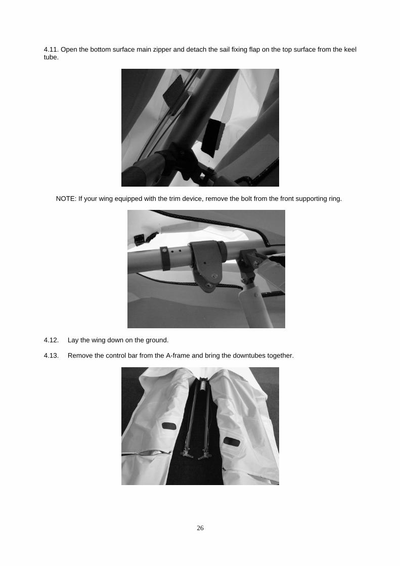
4.11. Open the bottom surface main zipper and detach the sail fixing flap on the top surface from the keel tube.
NOTE: If your wing equipped with the trim device, remove the bolt from the front supporting ring.
4.12. Lay the wing down on the ground.
4.13. Remove the control bar from the A-frame and bring the downtubes together.
26

4.14. Dismount the crossbar tensioning hook from the keel tube and also dismount the lower aft rigging wires from the keel tube.
4.15. Slide the sail slightly forward and get the nose of the frame out through the nose hole of the sail.
4.16. Bring the leading edges together and carefully slide the complete frame out through the nose
hole of the sail. If you encounter resistance, stop and find out what is hanging up.
NOTE: The sail installing is reverse to the sail removal procedure.
27

28
5.3. CHECKING THE TUBINGS
Section 5. INSPECTION OF THE WING
The sail should be inspected once every three months or after each 50 flying hours. The frame should be inspected once a year, after every 100 flying hours, and after every hard landing.
5.1. SAIL CHECK-UP 4.1.1. Checking the sail surface and seams. There should be no cuts, ruptures, threadbare holes and torn seams on the sail. Any torn seams should be re-stitched. Cuts and ruptures on the fairing and bottom surface (BS) of the sail that are not longer than 30 mm can be patched up with self-adhesive Dacron. The Dacron must be of a weight of not less than 100 g/m. larger cuts and ruptures are to be repaired by stitching on a reinforcing piece of the same fabric (stitched along the edges). Any rupture shorter than 50 mm can be repaired in this manner, but more complicated repairs and all cuts near the trailing edge should be carried out in the workshop of producing company. 4.1.2. Keep an eye on the sail grommets/eyelets and all areas of the sail that are subject to extra stress, especially the keel section, the nose section of leading edge and the outer tip section of leading edge. 5.2. CABLE SYSTEM
The cables must be checked for broken wires and corrosion. If any defect on a wire is observed, no matter how small, the cable in question MUST BE REPLACED. It is recommended that the entire cable system be replaced once every four years irrespective of service conditions. A NOTE ABOUT CABLES AND CABLE MAINTENANCE The cables which support the wing’s airframe are critical components of the wing’s structure, and must be maintained in an air worthy condition. It is a general practice in the design of aircraft structures to design to an ultimate strength of 1.5 times the highest expected load in normal service. PROFI TL cables, like other structural components on the wing, are typically designed with a structural safety factor of only about 50% above the expected maximum load. No significant loss in cable strength can be tolerated. A cable with even a single broken strand must be replaced before the wing is flown again. A cable which has been bent sharply enough to have taken a permanent set must also be replaced immediately. Some degree of fatigue due to repeated bending of cables is almost unavoidable in an aircraft that is assembled and disassembled with every flight.

29
o check the condition of the wing tubes the sail should be removed from the wing frame and e tubes should be detached at the joints. The tubes are to be inspected visually. When there
uestion should be inspected using a magnifying glass of (5-10) X magnification. There should be no trace of corrosion, cracks, bends or dents.
ds should be djusted if necessary. Check all the plastic batten heads and tails and replace if necessary.
5.5. FASTENERS
ed steners should be replaced. Bolts should not be worn and/or bent. Key bolts should be
hecked most thoroughly for cracks between the head and the bolt body. These are the bolts at nd bottom joints, the central spreader bar tensioning cable attach point
and the rear cable attachment point on the keel tube. If any cracks are observed - REPLACE
Tthis suspicion of damage, the points in q
Check that the uprights and the struts are straight and undamaged. If any defect on the uprights or the struts observed or you find them bended - replace immediately. 5.4. CHECKING THE BATTENS
The battens PROFI TL should be checked against the template and the bena
Check all fasteners (bolts, screws, rollers, nuts, splint pins etc.) for corrosion. Any corrodfacthe control bar side a
IMMEDIATELY!

Section 6. MAINTENANCE
6.1. WING TUNING
- The PROFI TL wing should fly straight and level without any pilot input with a cruising speed of between 70 kph and 140 kph using a trim device.
- Before making any adjustments to the wing, first check that the wing is in the standard condition and that the battens all conform to the PROFI TL batten.
- If the wing is not new, check the condition of the frame especially the outer leading edge tubes. The best is to remove the leading edges and check that they have the same bend in them and when under load they flex equally.
- Do not exceed the adjustment limitations. - Do one adjustment at a time and test fly each time to measure the effect of each
change. - Note all adjustments and changes in the log book. - Only tune the wing in perfect flying weather.
6.1.1. CG Adjustment
- Move the wing hang block forward on the wing keel will speed the wing up. - Swivel both wing tips down equally will speed the wing up.
6.1.2. Turn Trim
Each wingtip has a slotted plastic end cap
with a webbing strap over it. The plastic end is kept in place and at the correct angle with a small self-tapping screw. (Fig. 39)
By adjusting a wingtip down, the lift on the end of that wing will be increased and that will lift that wing in flight. Adjust the screw down by 2 mm at a time.
Do not exceed 6 mm away from the original position.
By adjusting the wingtip up, the lift will be decreased on that side and the wing will drop on that side. Adjust the screw up by 3 mm at a time.
Do not exceed 6 mm away from the original position.
Adjust one wingtip at a time and test fly after each adjustment. If the wing equipped with the winglets-correct the turns by short end tube rotating, as described above. The adjusting step is 2,5–5mm,using different hole lines.
Fig. 39
30

6.2. MAINTENANCE
- With correct maintenance your wing will retain its good condition for many years. - We recommend that do you not expose your wing to any more direct sunlight than
necessary. Do not leave it standing in the sun for long periods of time when you are not flying it.
- Do not leave your wing on the trike for a long period of time when the wind is strong. It will decrease the life of the sail; hang junction and frame of your wing.
- Your wing should be dried thoroughly after being exposed to rain or any other source of moisture.
- Your sail should never be washed with anything other then fresh water, as any soap or detergent will most likely degrade the cloth and may adversely affect the flight characteristics of your wing.
- If your wing is ever exposed to salt water you will need to have the wing completely disassembled in accordance with the recommended annual inspection procedure. All frame parts will need to be disassembled, including the removal of all sleeves and bushings, flushed liberally with fresh water, dried completely.
- When you set up or break down your wing, take care not to allow sand, soil and dirt to
enter the sail, batten pockets or tubes. Keep the leading edge tube telescopic connectors thoroughly clean as set up or break down will become difficult or impossible if they are dirty. Swab the tubes with a rag.
- Keep all the wing’s foam padding that was originally supplied and use in the same places when re-packing the wing.
6.3. STORAGE
- You can roll the trike with the topless wing into the most microlight hangars. If not flying for a long time, you should reassemble and store the wing in its bag in a dry place on soft bedding. Before storage you must ensure that the sail is dry.
- The frame of the wing must not be subjected to load during storage and the tubes must not be bent under their own weight.
- The wing can be storage in temperatures ranging from -10°C to +25°C. Notice; you can also store your mickrolight in hanger as it shown on picture. (Fig. 40)
Fig. 40 6.4. TRANSPORTATION
- The wing may be transported in its bag in any vehicle that offers protection from
mechanical damage, soiling and long exposure to rain. It is not recommended that the wing be carried or transported without its bag.

27
-
IN CLOSING - A FEW FINAL WORDS ON YOUR SAFETY
- UL flying is an active air sport with associated risks. Your safety can be greatly enhanced by following a few simple rules:
- Your wing is delivered to you ready to fly. Do not make any adjustments, which are not
described in this manual.
- Be sure the wing is properly adapted for your trike.
- If you are in doubt about any aspect of your trike or wing you should consult your dealer or Aeros for advice.
- Remember the Profi TL was designed for experienced pilots. Fly a wing suited to your
level of ability. A new risk may arise when you first fly a new type of the wing.
- The reactions of your new wing may well differ from those of the wing you where used to. In order to keep this risk low, we recommend that you gradually become familiar with your new wing.
- Before every take-off always do both an assembly check and a pre-flight check.
- Do not take off if the sail is wet, especially the leading edge, as the stall speed will
increase significantly.
- Always fly with a dry sail!
- Take special care to avoid ice covering the glider, particularly the leading edge in wintertime.
- A wet wing must be dried before storing. Do not leave your glider wet for more than one
day, because corrosion may result.
- Never fly alone.
- Don’t push your luck. It is your responsibility to know the limits of your wing and the limits of your own experience. Remember, that ultimately your safety is your responsibility.
- Fly only in places, which are suitable for flying.
- With proper care and maintenance, your wing will retain a high level of airworthiness for
many years.
Have fun. Fly safely. Aeros Team

28
LOG BOOK
TABLE OF FLIGHT HOURS
DATE NUMBER OF FLIGHT TOTAL HOURS BY WHOM


Кол. на изделие - 1шт.
438.11
Инв
. № подл.
Справ
. №Взам
. инв
. №Перв.
примен
.
Копировал Формат А3
Подпись
и дат
а
PRF15.TL.643.001.AD
1
"AEROS"
27.04.11
14.07.11
PRF15.TL.643.001.AD
1:1 LE Tube №4 Right (Труба боковая №4 правая)
PRF15.TL.643.001.AD
Разраб.
Нач. КБ
Утв.Н.контр.
Листов 3Лист 1Т.контр.Пров.
ДатаПодп.№ докум.ЛистИзм.МасштабМассаЛит.
Подпись
и дат
аИнв
. № дубл.
(560;480)
C-C
28°
6,1
A-A
24°
4,2
31
2-Tapping Screw 2.2x6.5
1
1-PRF15.141.000
3-Tapping Screw 4.2x136-PRF15.TL.643.003.R 5-PRF15.TL.643.003.AD465 80
545
A
A
C
C
B
B
45°30'
B-B
2отв
.
24°
4,2
17°
14°
3
PRF15.TL.643.001.AD - Tube №4 Правая - показанаPRF15.TL.643.002.AD - Tube №4 Левая - зеркальное отображение
Размеры для справок.
Top Related