


Languages
Pages
Legal

.
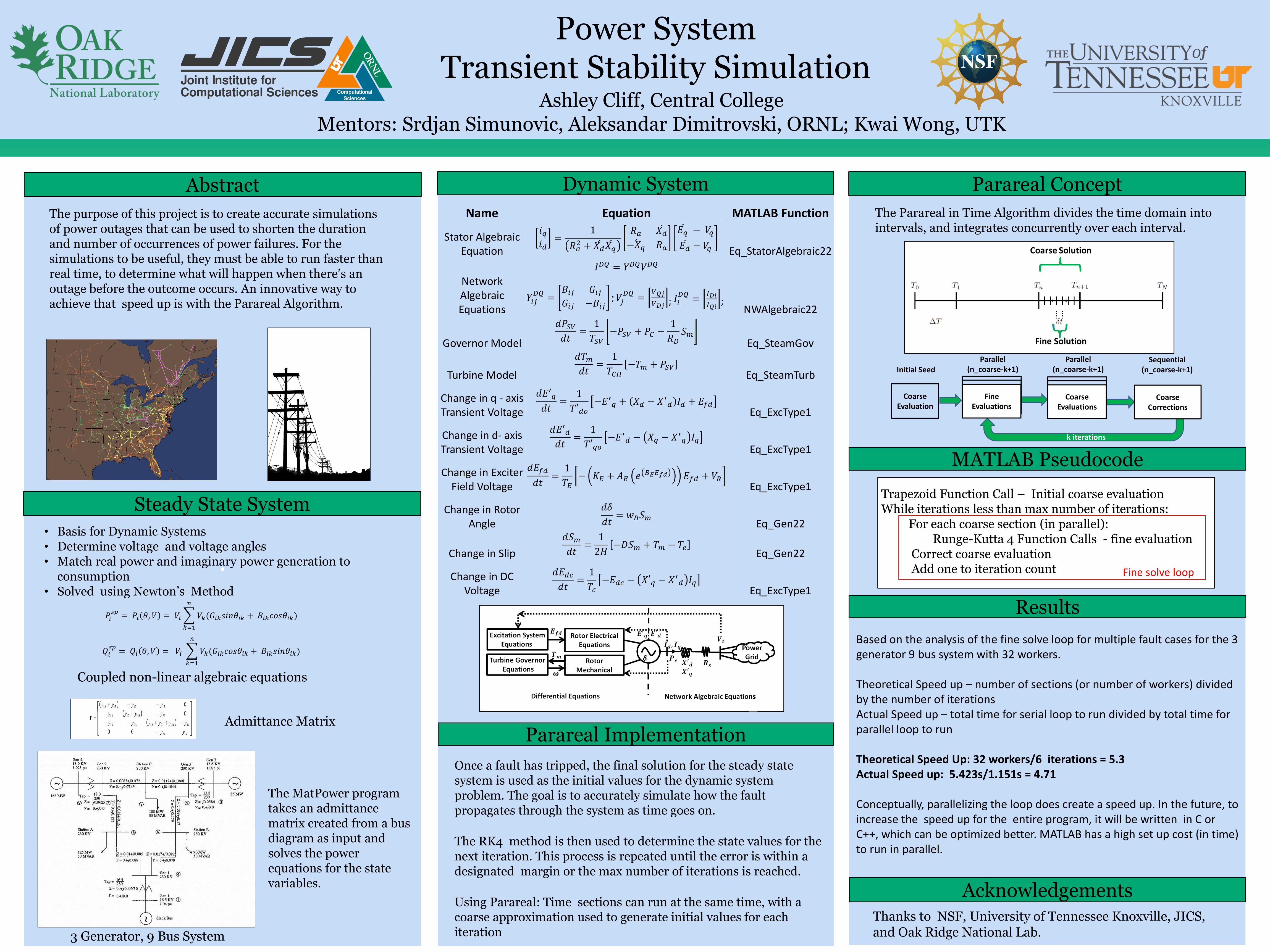
Power System Transient Stability Simulation
Parareal Concept
Parareal Implementation
Abstract Dynamic System
Ashley Cliff, Central CollegeMentors: Srdjan Simunovic, Aleksandar Dimitrovski, ORNL; Kwai Wong, UTK
Acknowledgements
Steady State System
The purpose of this project is to create accurate simulations of power outages that can be used to shorten the duration and number of occurrences of power failures. For the simulations to be useful, they must be able to run faster than real time, to determine what will happen when there’s an outage before the outcome occurs. An innovative way to achieve that speed up is with the Parareal Algorithm.
• Basis for Dynamic Systems• Determine voltage and voltage angles• Match real power and imaginary power generation to
consumption• Solved using Newton’s Method
Coarse Evaluation
Initial SeedParallel
(n_coarse-k+1)Sequential
(n_coarse-k+1)
Coarse Corrections
k iterations
Fine Evaluations
Parallel(n_coarse-k+1)
Coarse Evaluations
Coupled non-linear algebraic equations
3 Generator, 9 Bus System
The Parareal in Time Algorithm divides the time domain into intervals, and integrates concurrently over each interval.
Once a fault has tripped, the final solution for the steady state system is used as the initial values for the dynamic system problem. The goal is to accurately simulate how the fault propagates through the system as time goes on.
The RK4 method is then used to determine the state values for the next iteration. This process is repeated until the error is within a designated margin or the max number of iterations is reached.
Using Parareal: Time sections can run at the same time, with a coarse approximation used to generate initial values for each iteration
Thanks to NSF, University of Tennessee Knoxville, JICS, and Oak Ridge National Lab.
Trapezoid Function Call – Initial coarse evaluationWhile iterations less than max number of iterations:
For each coarse section (in parallel):Runge-Kutta 4 Function Calls - fine evaluation
Correct coarse evaluationAdd one to iteration count
MATLAB Pseudocode
Results
Admittance Matrix
The MatPower program takes an admittance matrix created from a bus diagram as input and solves the power equations for the state variables.
𝑃𝑖𝑠𝑝
= 𝑃𝑖 𝜃, 𝑉 = 𝑉𝑖
𝑘=1
𝑛
𝑉𝑘(𝐺𝑖𝑘𝑠𝑖𝑛𝜃𝑖𝑘 + 𝐵𝑖𝑘𝑐𝑜𝑠𝜃𝑖𝑘)
𝑄𝑖𝑠𝑝
= 𝑄𝑖 𝜃, 𝑉 = 𝑉𝑖
𝑘=1
𝑛
𝑉𝑘(𝐺𝑖𝑘𝑐𝑜𝑠𝜃𝑖𝑘 + 𝐵𝑖𝑘𝑠𝑖𝑛𝜃𝑖𝑘)
Name Equation MATLAB Function
Stator Algebraic Equation
𝑖𝑞
𝑖𝑑=
1
𝑅𝑎2 + 𝑋𝑑
𝑋𝑞
𝑅𝑎 𝑋𝑑
−𝑋𝑞 𝑅𝑎
𝐸𝑞 − 𝑉𝑞
𝐸𝑑 − 𝑉𝑞 Eq_StatorAlgebraic22
Network Algebraic Equations
𝐼𝐷𝑄 = 𝑌𝐷𝑄𝑉𝐷𝑄
𝑌𝑖𝑗𝐷𝑄
=𝐵𝑖𝑗 𝐺𝑖𝑗
𝐺𝑖𝑗 −𝐵𝑖𝑗; 𝑉𝑗
𝐷𝑄=
𝑉𝑄𝑗
𝑉𝐷𝑗; 𝐼𝑖
𝐷𝑄=
𝐼𝐷𝑖
𝐼𝑄𝑖;
NWAlgebraic22
Governor Model
𝑑𝑃𝑆𝑉
𝑑𝑡=
1
𝑇𝑆𝑉−𝑃𝑆𝑉 + 𝑃𝐶 −
1
𝑅𝐷𝑆𝑚
Eq_SteamGov
Turbine Model
𝑑𝑇𝑚
𝑑𝑡=
1
𝑇𝐶𝐻−𝑇𝑚 + 𝑃𝑆𝑉
Eq_SteamTurb
Change in q - axis Transient Voltage
𝑑𝐸′𝑞
𝑑𝑡=
1
𝑇′𝑑𝑜−𝐸′
𝑞 + 𝑋𝑑 − 𝑋′𝑑 𝐼𝑑 + 𝐸𝑓𝑑
Eq_ExcType1
Change in d- axis Transient Voltage
𝑑𝐸′𝑑
𝑑𝑡=
1
𝑇′𝑞𝑜−𝐸′
𝑑 − 𝑋𝑞 − 𝑋′𝑞 𝐼𝑞
Eq_ExcType1
Change in Exciter Field Voltage
𝑑𝐸𝑓𝑑
𝑑𝑡=
1
𝑇𝐸− 𝐾𝐸 + 𝐴𝐸 𝑒 𝐵𝐸𝐸𝑓𝑑 𝐸𝑓𝑑 + 𝑉𝑅
Eq_ExcType1
Change in Rotor Angle
𝑑𝛿
𝑑𝑡= 𝑤𝐵𝑆𝑚
Eq_Gen22
Change in Slip
𝑑𝑆𝑚
𝑑𝑡=
1
2𝐻−𝐷𝑆𝑚 + 𝑇𝑚 − 𝑇𝑒
Eq_Gen22
Change in DC Voltage
𝑑𝐸𝑑𝑐
𝑑𝑡=
1
𝑇𝑐−𝐸𝑑𝑐 − 𝑋′𝑞 − 𝑋′
𝑑 𝐼𝑞Eq_ExcType1
Based on the analysis of the fine solve loop for multiple fault cases for the 3 generator 9 bus system with 32 workers.
Theoretical Speed up – number of sections (or number of workers) divided by the number of iterationsActual Speed up – total time for serial loop to run divided by total time for parallel loop to run
Theoretical Speed Up: 32 workers/6 iterations = 5.3Actual Speed up: 5.423s/1.151s = 4.71
Conceptually, parallelizing the loop does create a speed up. In the future, to increase the speed up for the entire program, it will be written in C or C++, which can be optimized better. MATLAB has a high set up cost (in time) to run in parallel.
Fine solve loop
Top Related