


Languages
Pages
Legal


Torsion damper design
A snapshot of Vibromech’s design and development services
Vibromech Engineers & Services Ltd.
115, Industrial Estate, Perungudi,
Chennai, Tamil Nadu, India,
600 096
©VESL 2002
Black Box Design & Development
➢ Basic inputs from customer➢ Engine data questionnaire➢ CAD data➢ Material properties
➢ Concept selection and detailed design➢ Proto development, testing and validation➢ APQP and customer specific systems
©VESL 2002
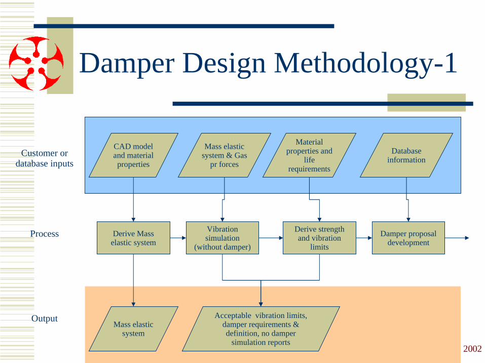
Damper Design Methodology-1
Derive Mass elastic system
Vibration simulation
(without damper)
Derive strength and vibration
limits
Damper proposal development
CAD model and material properties
Mass elastic system & Gas
pr forces
Mass elastic system
Material properties and
life requirements
Acceptable vibration limits, damper requirements & definition, no damper
simulation reports
Database information
Customer or database inputs
Process
Output
©VESL 2002
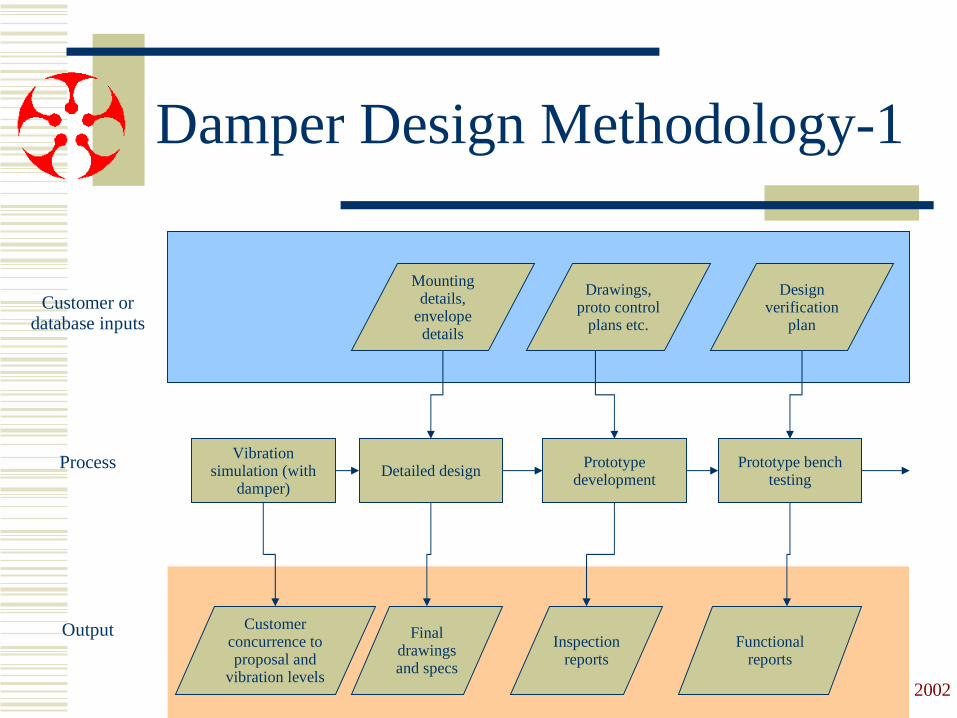
Damper Design Methodology-1
Vibration simulation (with
damper)Detailed design Prototype
developmentPrototype bench
testing
Mounting details,
envelope details
Customer concurrence to proposal and
vibration levels
Final drawings and specs
Design verification
plan
Functional reports
Customer or database inputs
Process
OutputInspection
reports
Drawings, proto control
plans etc.
©VESL 2002
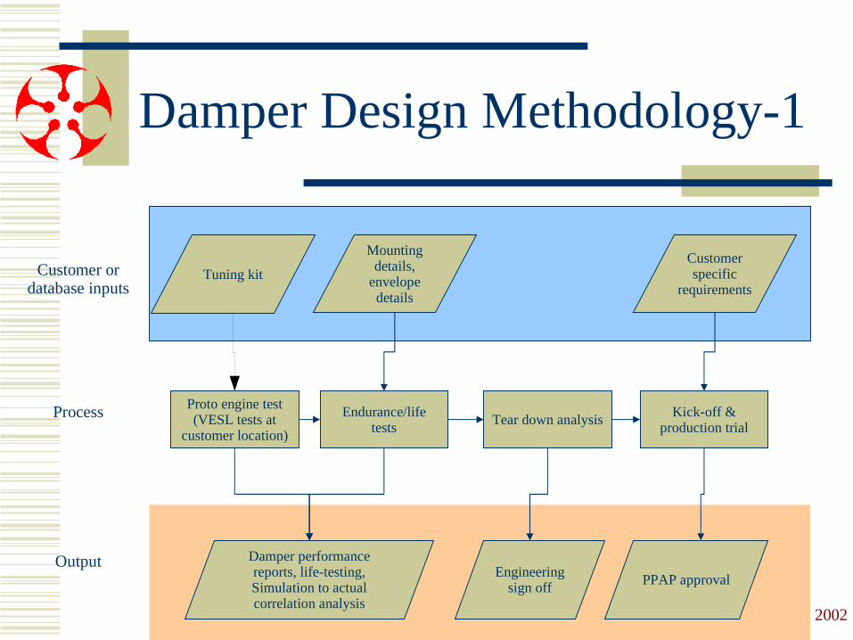
Damper Design Methodology-1
Proto engine test (VESL tests at
customer location)
Endurance/life tests
Tear down analysis Kick-off & production trial
Mounting details,
envelope details
Damper performance reports, life-testing, Simulation to actual correlation analysis
Customer specific
requirements
PPAP approval
Customer or database inputs
Process
OutputEngineering
sign off
Tuning kit

©VESL 2002
Customer inputs
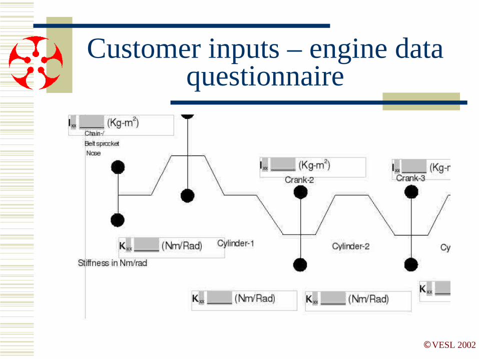
➢ Customer inputs➢ 11 page questionnaire➢ Functional requirements➢ Mounting details➢ Simulation inputs
➢ Customer specific requirements➢ Life➢ Warranty➢ System requirements and guidelines
©VESL 2002
Customer inputs – engine data questionnaire

©VESL 2002
Vibration simulation
➢ Determine no-damper vibration levels
➢ Determine type of vibration➢ Rigid body➢ Torsional
➢ Mode shapes and frequencies
©VESL 2002
Vibration simulation
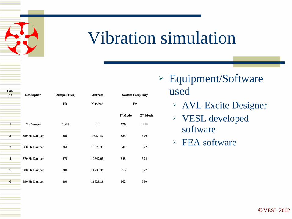
➢ Equipment/Software used➢ AVL Excite Designer➢ VESL developed
software➢ FEA software
Case No Description Damper Freq Stiffness System Frequency
Hz N-m/rad Hz
1st Mode 2nd Mode
1 No Damper Rigid Inf 526 1410
2 350 Hz Damper 350 9527.13 333 520
3 360 Hz Damper 360 10079.31 341 522
4 370 Hz Damper 370 10647.05 348 524
5 380 Hz Damper 380 11230.35 355 527
6 390 Hz Damper 390 11829.19 362 530
©VESL 2002
Vibration simulation
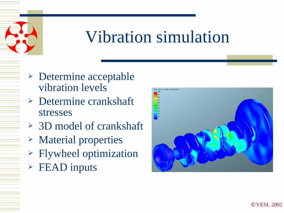
➢ Determine acceptable vibration levels
➢ Determine crankshaft stresses
➢ 3D model of crankshaft➢ Material properties➢ Flywheel optimization➢ FEAD inputs
©VESL 2002
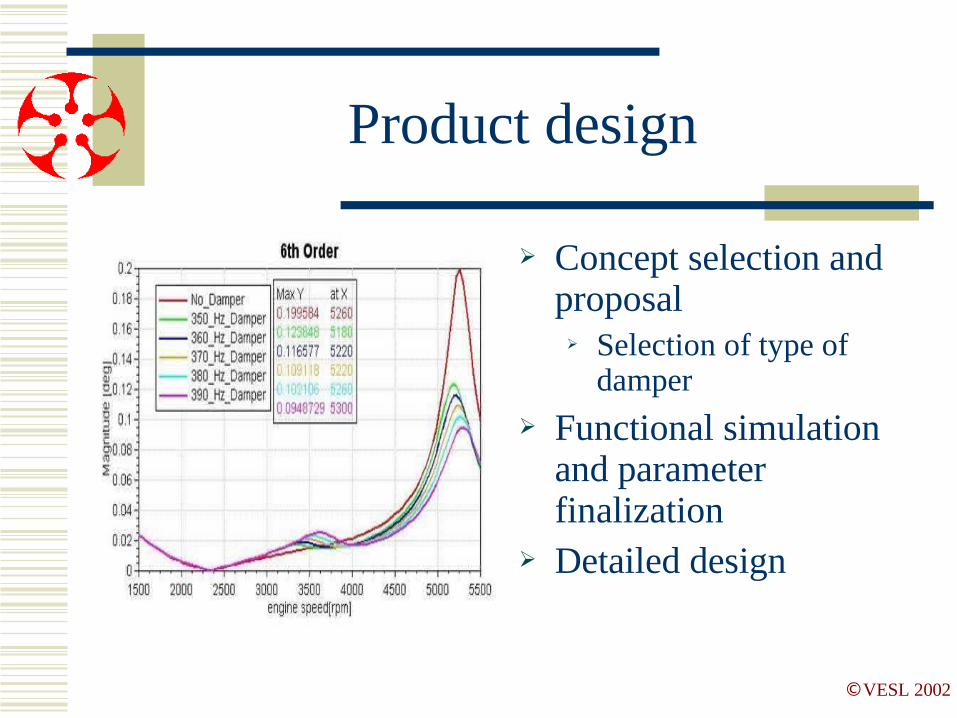
Product design
➢ Concept selection and proposal➢ Selection of type of
damper➢ Functional simulation
and parameter finalization
➢ Detailed design
©VESL 2002
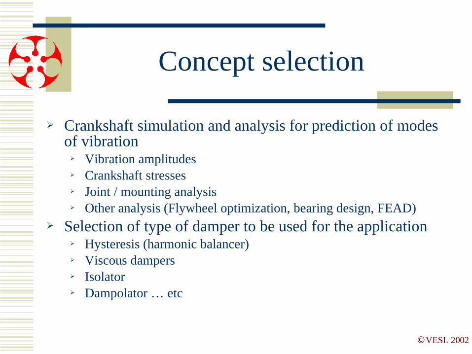
Concept selection
➢ Crankshaft simulation and analysis for prediction of modes of vibration➢ Vibration amplitudes➢ Crankshaft stresses➢ Joint / mounting analysis➢ Other analysis (Flywheel optimization, bearing design, FEAD)
➢ Selection of type of damper to be used for the application➢ Hysteresis (harmonic balancer)➢ Viscous dampers➢ Isolator➢ Dampolator … etc

©VESL 2002
Concept proposal and selection
➢ Considerations➢ Performance➢ Strength➢ Ease of manufacture / process complexity➢ Detail design
➢ Examples in next slides
©VESL 2002
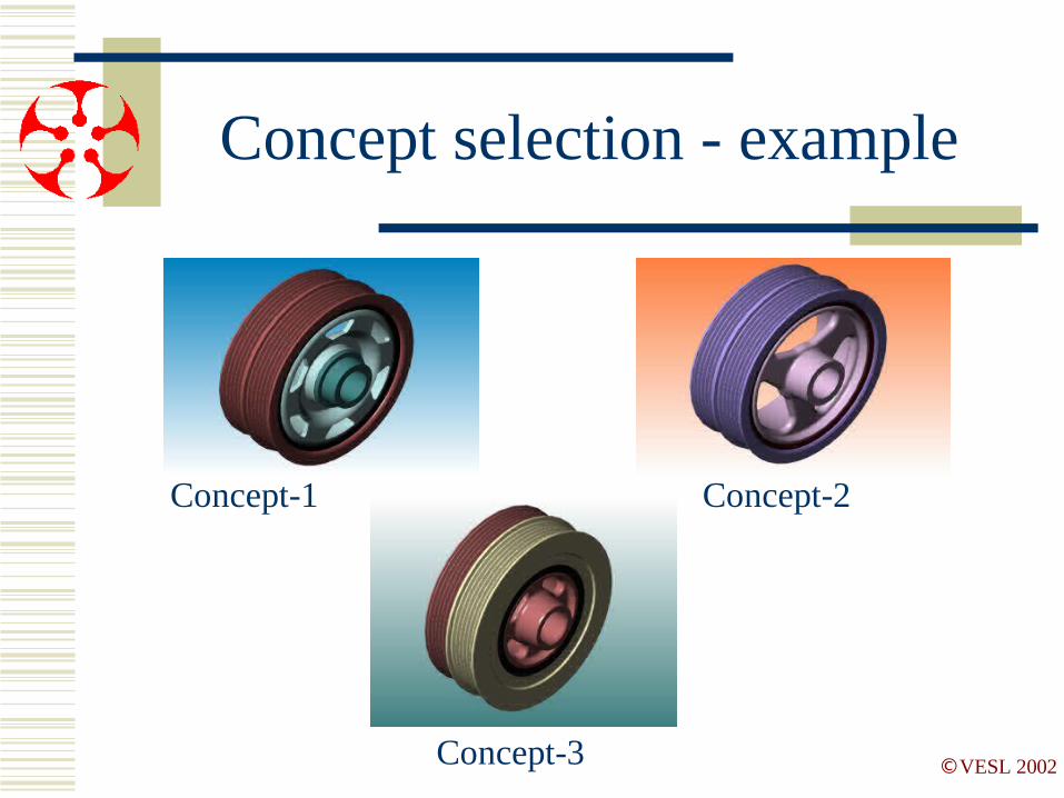
Concept selection - example
Concept-1 Concept-2
Concept-3

©VESL 2002
Factor of safety
Concept_1 : 2.01
Concept_2 : 2.54
Concept_3 : 3.16
Von misses stress
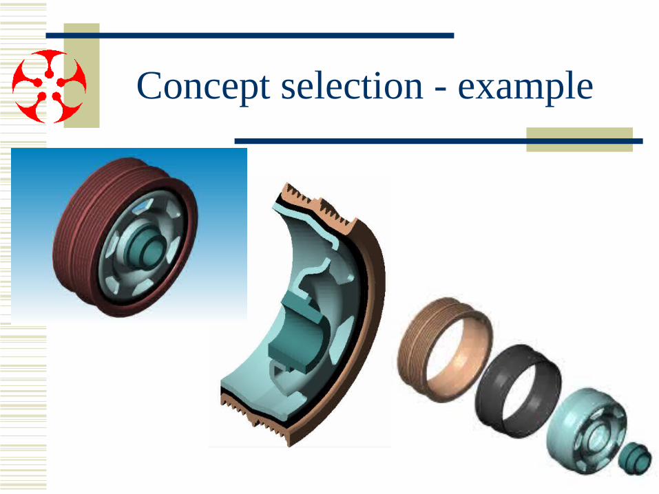
Concept selection - example
©VESL 2002
Concept selection - example
©VESL 2002
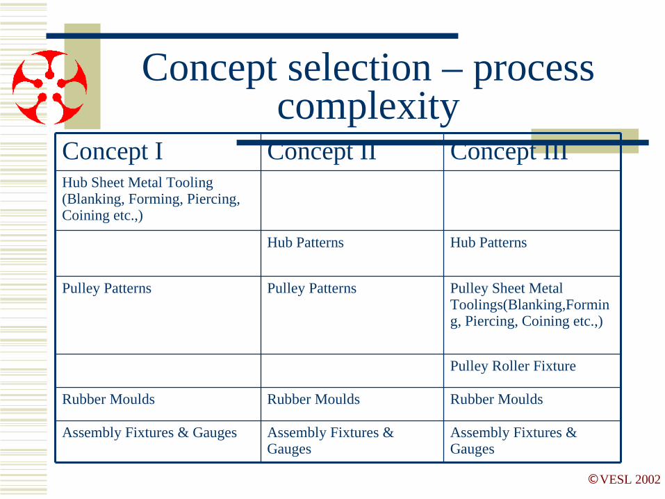
Concept selection – process complexity
Hub PatternsHub Patterns
Assembly Fixtures & Gauges
Assembly Fixtures & Gauges
Assembly Fixtures & Gauges
Rubber MouldsRubber Moulds Rubber Moulds
Pulley Roller Fixture
Pulley Sheet Metal Toolings(Blanking,Forming, Piercing, Coining etc.,)
Pulley PatternsPulley Patterns
Hub Sheet Metal Tooling (Blanking, Forming, Piercing, Coining etc.,)
Concept IIIConcept IIConcept I
©VESL 2002
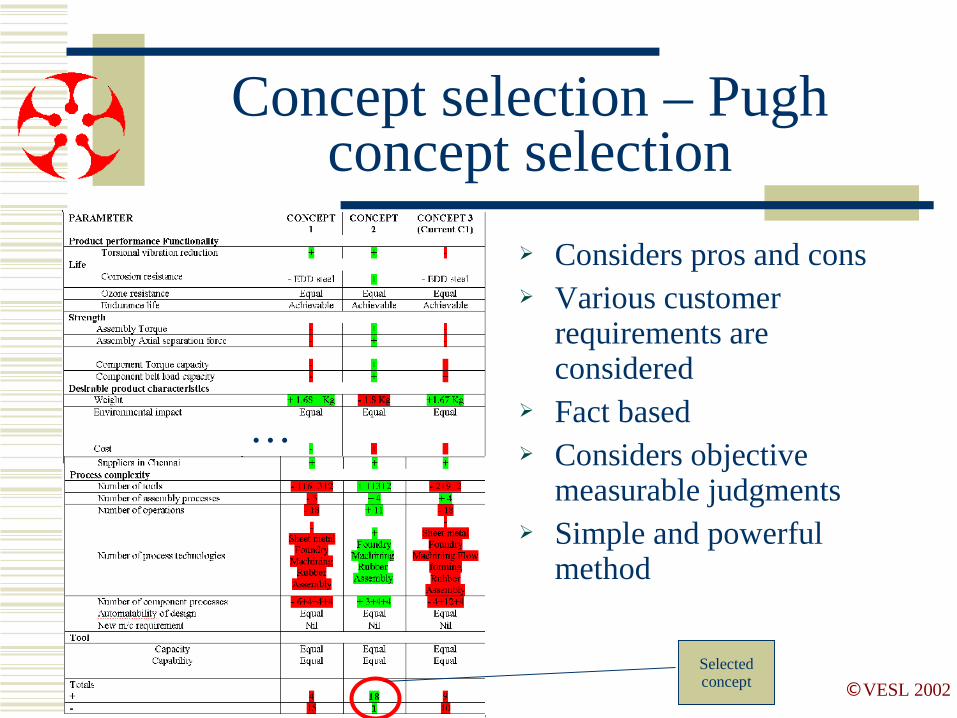
Concept selection – Pugh concept selection
➢ Considers pros and cons➢ Various customer
requirements are considered
➢ Fact based➢ Considers objective
measurable judgments➢ Simple and powerful
method
…
Selected concept
©VESL 2002
Detailed design
➢ Strength➢ Mounting analysis
➢ Crank-nose torque➢ Power dissipated➢ Packaging➢ FEAD provisions➢ Other accessories

©VESL 2002
Detailed design
©VESL 2002
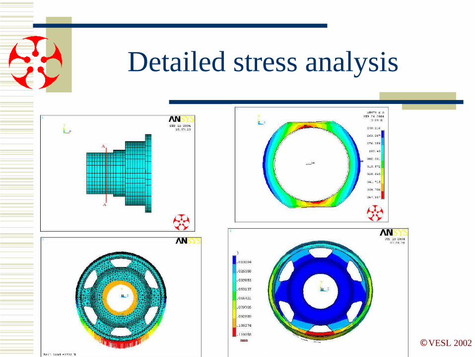
Detailed stress analysis

©VESL 2002
CAE Capability
➢ CAD facilities in place➢ Interfaces to customer CAD requirements
possible➢ ProE in use, converters available
➢ Finite element analysis➢ Product analysis➢ Design optimization

©VESL 2002
Prototype development
➢ Manufacture➢ Prototype shop
➢ Vertical machining centers➢ CNC➢ Skilled operators➢ Experienced supervisors
➢ Tool room➢ Pattern manufacture➢ Sheet metal tooling➢ Jigs fixtures➢ Flow forming tooling

©VESL 2002
Prototype development
➢ 6-8 weeks for proto development
➢ Daily plan and review➢ Production intent tool
design➢ Inserts maybe soft (not heat
treated)➢ Tool design will be carried
over for production with hardened inserts
➢ APQP and review

©VESL 2002
Product test lab
©VESL 2002
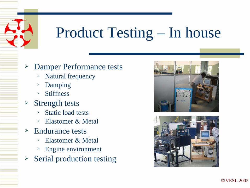
Product Testing – In house
➢ Damper Performance tests➢ Natural frequency➢ Damping➢ Stiffness
➢ Strength tests➢ Static load tests➢ Elastomer & Metal
➢ Endurance tests➢ Elastomer & Metal➢ Engine environment
➢ Serial production testing

©VESL 2002
Product Testing - Customer
➢ Engine testing➢ Performed at the
customer by us➢ Test equipment
available with us➢ Engine endurance➢ Tear down analysis➢ Tested sample analysis

Vibromech Engineers & Services Ltd ©VESL 2002
Reality check – Tuning kit
6th Order correlation on tuned mass elastic system
0
0.05
0.1
0.15
0.2
0.25
0.3
0.35
0.4
Mag
nitu
de [
deg
]
1000 2000 3000 4000 5000
engine speed
VESL Measured data : 390 Hz Damper @ 60 deg CVESL Measured data : Solid Pulley (no-damping) M&M Measured data : 390 + /- 30 Hz DamperNo DamperSolidpulley+ Adopter: S_0_H_0024_0028_00039390 HZ Damper + Adopter : S_0039_H_0024_0028390 Hz Damper w ithout Adopter: S_0039_H_0024
Comparison of Simulated
and measured
data
©VESL 2002
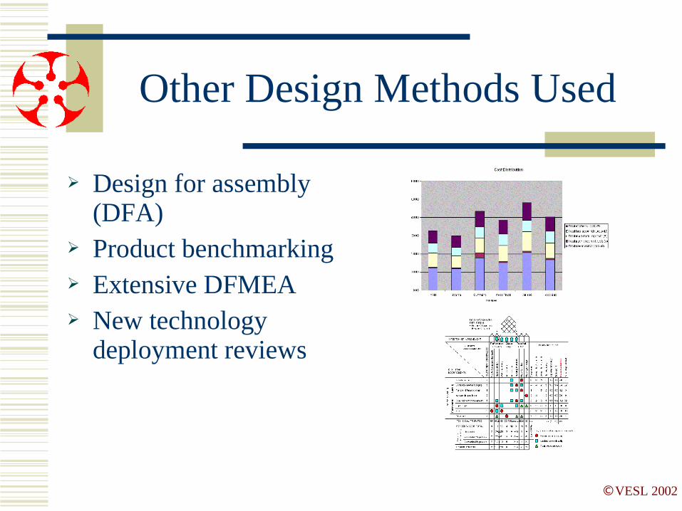
Other Design Methods Used
➢ Design for assembly (DFA)
➢ Product benchmarking➢ Extensive DFMEA➢ New technology
deployment reviews

©VESL 2002
Summary Slide
➢ Black box design & development capability➢ CAE capability
➢ CAD, FEA ➢ Other advanced methods in use
➢ DOE, DFA➢ Quick prototype development 6-8 wks➢ Full range of product and design validation

©VESL 2002
Questions
➢ Commercial➢ [email protected]
➢ Technical➢ [email protected]
➢ Phone➢ +91(44) 52005330
➢ Fax➢ +91(44) 52005340
Top Related