


Languages
Pages
Legal


Prepared for: City of Oshkosh Oshkosh, Wisconsin
Subsurface Exploration and Geotechnical Engineering Evaluation for the Proposed Tipler Retention Pond Project
AECOM, Inc. April 2009 Document No.: 60099626

AECOM
i May 2009
Contents Executive Summary ......................................................................................................................................ES-1
1.0 Field Procedures.................................................................................................................................... 1-1
2.0 Exploration Results ............................................................................................................................... 2-1
3.0 Monitoring Well Installation.................................................................................................................. 3-2
4.0 Environmental Screening ..................................................................................................................... 4-1
5.0 Construction Considerations............................................................................................................... 5-1
6.0 General Qualifications........................................................................................................................... 6-1
List of Appendices Appendix A Boring Location Diagram / Boring Logs / Abandonment Forms / Monitoring Well Construction Forms
Appendix B AECOM General Notes
Appendix C AECOM Field and Laboratory Procedures
Appendix D AECOM Soil Classification System Chart

AECOM
ES-1 May 2009
Executive Summary
The City of Oshkosh is proposing that a retention pond be constructed in the field located to the west of Tipler Middle School. Excavations up to 15 feet in depth will be required for the retention pond construction.
The purpose of this exploration program was to identify the soil and groundwater conditions within the depths of the excavations proposed, with special emphasis on any apparent bedrock conditions encountered within the depth of the borings. In addition, field screening of the soil samples with a PID was completed to identify potential environmentally impacted soil.
AECOM
60099623-Tipler Retention Pond 1-1 May 2009
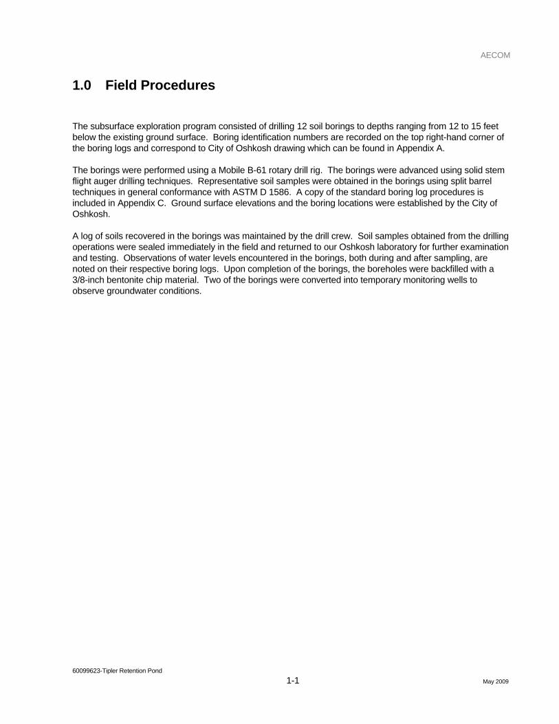
1.0 Field Procedures
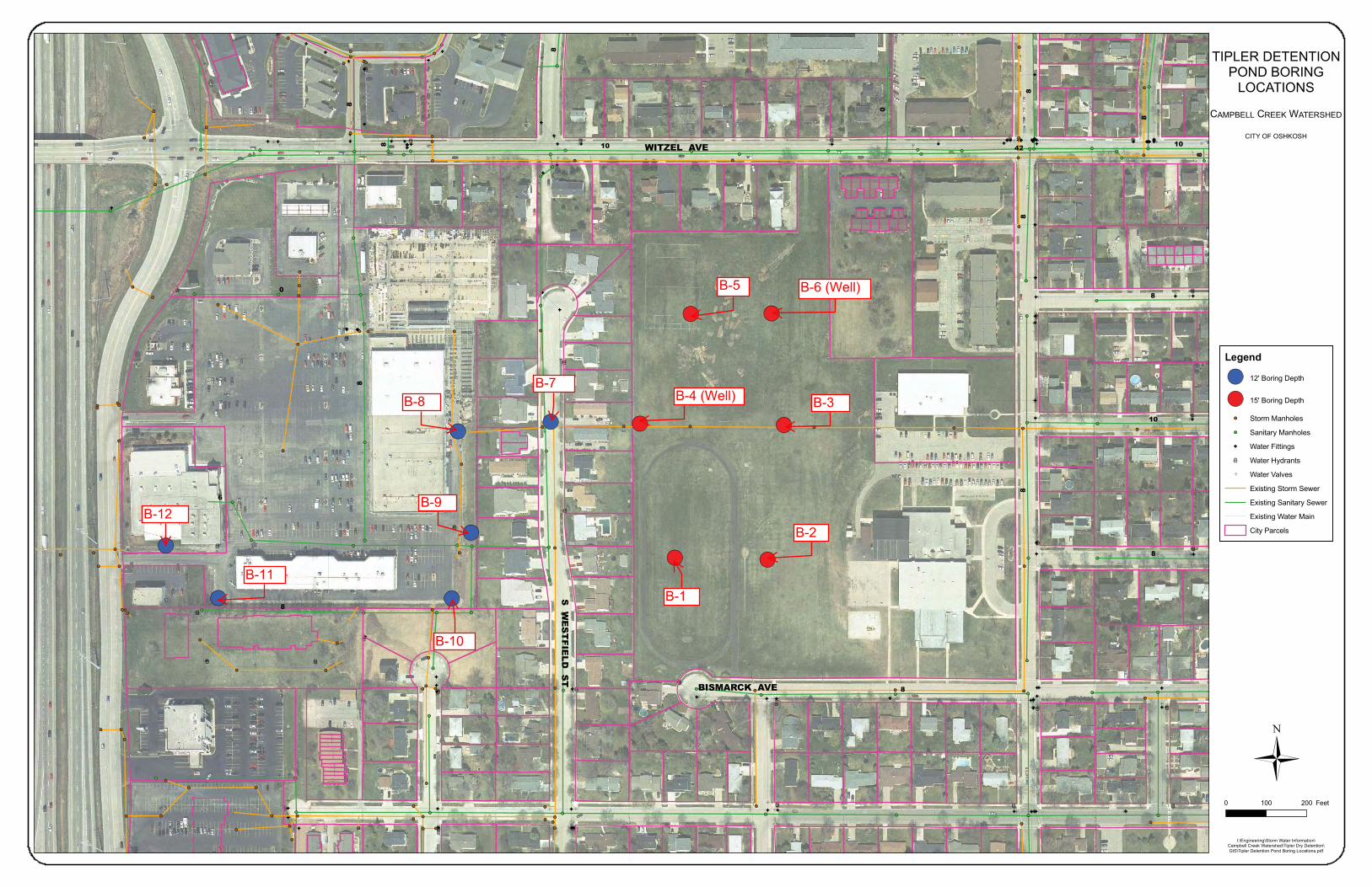
The subsurface exploration program consisted of drilling 12 soil borings to depths ranging from 12 to 15 feet below the existing ground surface. Boring identification numbers are recorded on the top right-hand corner of the boring logs and correspond to City of Oshkosh drawing which can be found in Appendix A.
The borings were performed using a Mobile B-61 rotary drill rig. The borings were advanced using solid stem flight auger drilling techniques. Representative soil samples were obtained in the borings using split barrel techniques in general conformance with ASTM D 1586. A copy of the standard boring log procedures is included in Appendix C. Ground surface elevations and the boring locations were established by the City of Oshkosh.
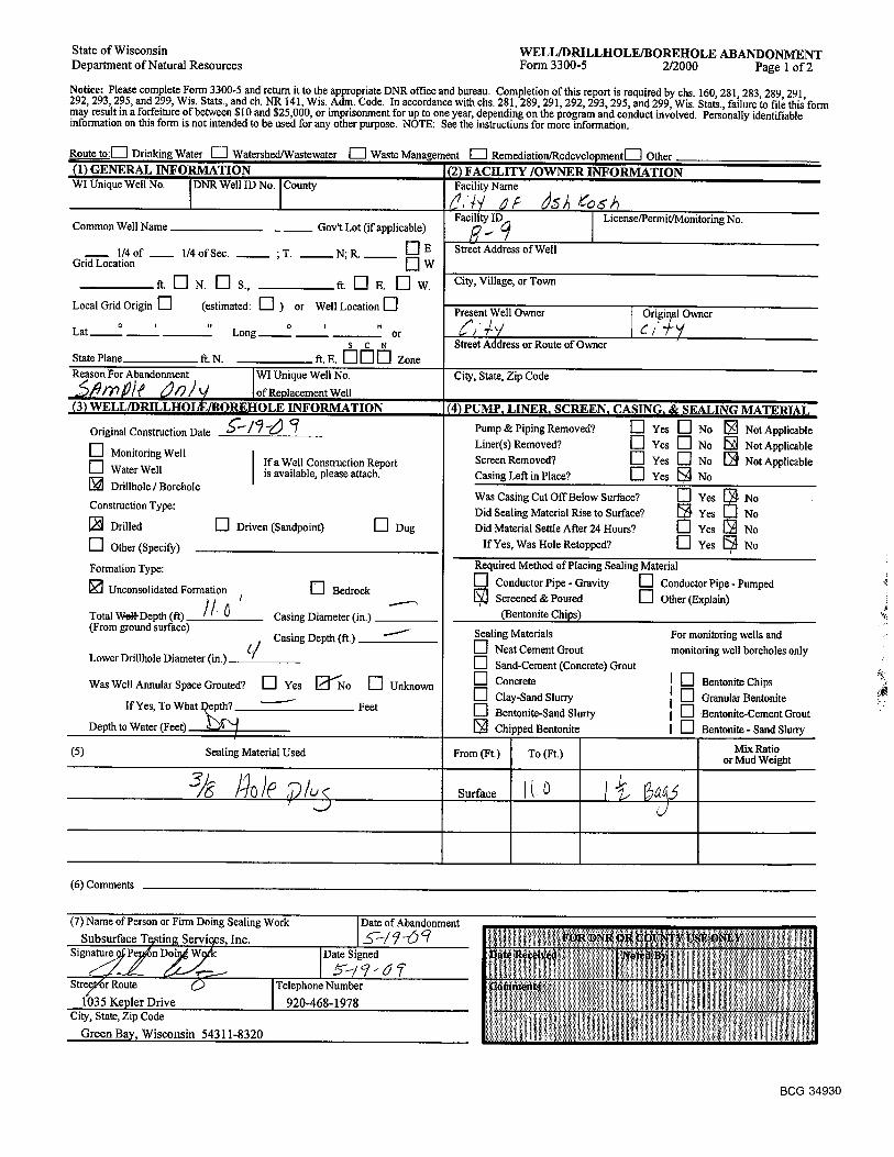
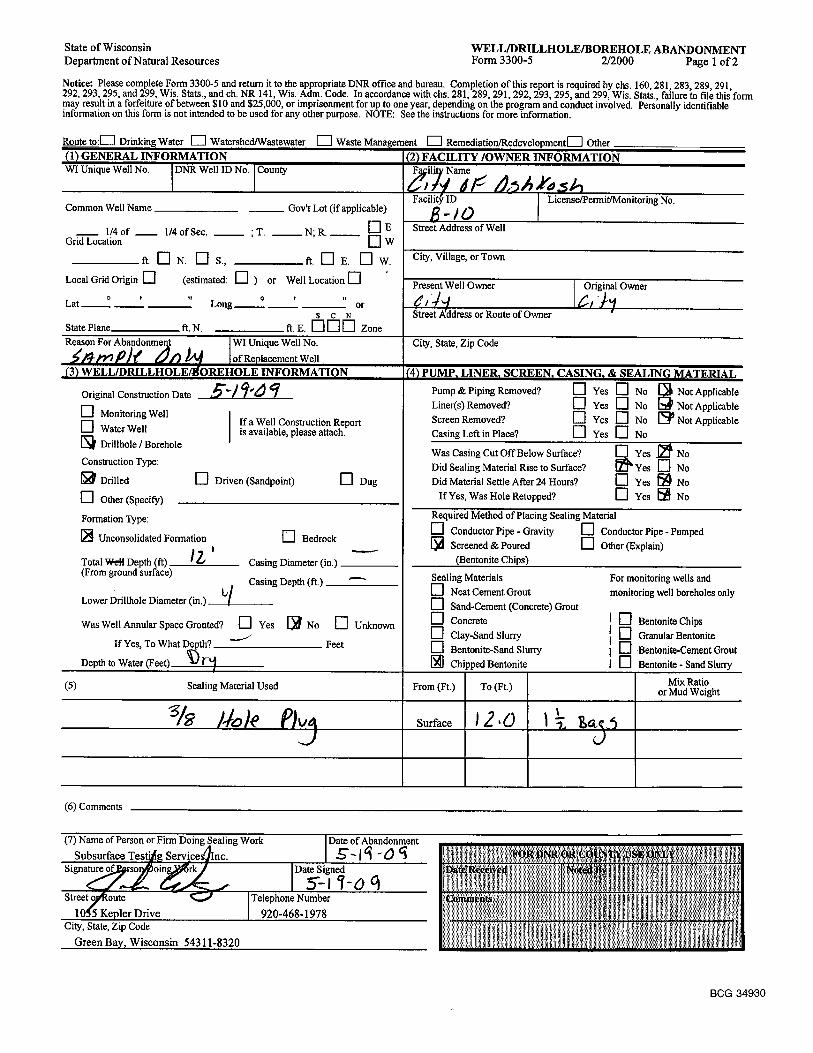
A log of soils recovered in the borings was maintained by the drill crew. Soil samples obtained from the drilling operations were sealed immediately in the field and returned to our Oshkosh laboratory for further examination and testing. Observations of water levels encountered in the borings, both during and after sampling, are noted on their respective boring logs. Upon completion of the borings, the boreholes were backfilled with a 3/8-inch bentonite chip material. Two of the borings were converted into temporary monitoring wells to observe groundwater conditions.

AECOM
60099623-Tipler Retention Pond 2-1 May 2009
2.0 Exploration Results
One of the twelve borings encountered a surface pavement section. The concrete and base course thickness was recorded and appears on the boring log.
Underlying the surface fill materials, which were mainly composed of topsoil except for Borings 7 and 12 which encountered pavement and base course, the fill material extended to a depth of 0.5 to 3.5 feet below grade. A reddish-brown to brown silty clay was encountered that extended to a depth of 1 to 15 feet below grade. This natural silty clay generally ranged in consistency from very stiff to hard, as indicated by the unconfined compressive strength estimates. Below the silty clay, a gray or brown sandy silt or silty sand was encountered in a few of the borings to the termination depth of the borings. This hardpan type material ranged in relative density from medium dense to extremely dense, as indicated by the Standard Penetration Test blow counts.
In general, groundwater was not encountered while advancing the borings through the overburden soils with solid-stem flight augers. Groundwater was observed in Boring 4 at a depth of 13.5 feet and Boring 8 at a depth of 8.3 feet. However, the majority of the soils within the profile were cohesive in nature and have a relatively low permeability. The two monitoring wells will be monitored to accurately determine groundwater levels.

AECOM
60099623-Tipler Retention Pond 3-2 May 2009
3.0 Monitoring Well Installation
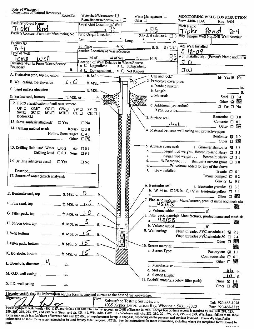
Monitoring wells were installed in soil borings B-4 and B-6. The wells were set at a depth of 15 feet. The wells were constructed with schedule 40 PVC with a 10-foot screen. A 2-foot stick-up was extended above the ground surface. The monitoring well construction form can be found in Appendix A. Groundwater levels will be monitored to observe where groundwater may be encountered during excavation.

AECOM
60099623-Tipler Retention Pond 4-1 May 2009
4.0 Environmental Screening
All soil samples were screened using a photoionization detector (PID). There were no elevated PID readings.

AECOM
60099623-Tipler Retention Pond 5-1 May 2009
5.0 Construction Considerations
The overburden soils encountered within the depth of the borings can be excavated effectively with backhoe-type equipment. A few cobbles and boulders were encountered within the profile which could hinder excavation depending on their actual dimension. Sideslopes of the excavations in the cohesive soils and hardpan soils will be reasonably stable at relatively steep slopes of approximately 1H:1V. However, all excavations should conform to local, state, federal and OSHA requirements.

AECOM
60099623-Tipler Retention Pond 6-1 May 2009
6.0 General Qualifications
This report has been prepared in general accordance with normally accepted geotechnical engineering practices to aid in the evaluation of this site and to assist our Client in the design of this project. We have prepared this report for the purpose intended by our Client, and reliance on its contents by anyone other than our Client is done at the sole risk of the user. No other warranty, either expressed or implied, is made.
The scope is limited to the specific project and location described herein, and our description of the project represents our understanding of the significant aspects relevant to the geotechnical characteristics.
The analysis and recommendations submitted in this report are based on the data obtained from the soil borings performed at the locations indicated on the boring logs and from the information discussed in this report. This report does not reflect any variations which may occur between the borings. In the performance of subsurface explorations, specific information is obtained at specific locations at specific times. However, it is a well-known fact that variations in soil and rock conditions exist on most sites between boring locations and that seasonal and annual fluctuations in groundwater levels will likely occur. The nature and extent of variations may not become evident until the course of construction.
The scope of services for this project does not include either specifically or by implication any environmental or biological (e.g., mold, fungi, bacteria, viruses, and the byproducts of such organisms) assessment of the site, or identification of or prevention of pollutants, hazardous materials, or conditions. Other studies beyond the scope of this project would be required to evaluate the potential of such contamination or pollution.

AECOM
May 2009
Appendix A Boring Location Diagram / Boring Logs / Abandonment Forms / Monitoring Well Construction Forms
S W
ES
TF
IE
LD
ST
WITZEL AVE
BISMARCK AVE
4210
8
0
6
0
8
8
8
8
10
8
8
8
8
8
10
8
8
8
CAMPBELL CREEK WATERSHED
CITY OF OSHKOSH
TIPLER DETENTIONPOND BORING
LOCATIONS
Legend
12' Boring Depth
15' Boring Depth
Storm Manholes
Sanitary Manholes
Water Fittings
Water Hydrants
Water Valves
Existing Storm Sewer
Existing Sanitary Sewer
Existing Water Main
City Parcels
0 200100 Feet
I:\Engineering\Storm Water Information\Campbell Creek Watershed\Tipler Dry Detention\
GIS\Tipler Detention Pond Boring Locations.pdf
B-6 (Well)B-5
B-3
B-2
B-1
B-4 (Well)B-7
B-8
B-9
B-10
B-11
B-12

1.5
15.0* Calibrated Penetrometer
1
2
3
4
5
6
7
SS
SS
SS
SS
SS
SS
SS
Fill: Topsoil - Moist
Reddish brown silty clay - trace gravel - moist - very stiff (CL)
End of BoringBoring advanced to 15.0 feet with solid-stem augerBoring backfilled with 3/8" chipped bentonite
7
12
12
16
15
13
15
*
*
* *
*
*
SA
MP
LE D
ISTA
NC
E
SA
MP
LE T
YP
E
PROJECT NAMECity of Oshkosh
SA
MP
LE N
O.
10 20 30 40 50
1 2 3 4 5
LIQUIDLIMIT %
UNCONFINED COMPRESSIVE STRENGTHTONS/FT.2
PLASTICLIMIT %
Tipler Pond
WATERCONTENT %
10 20 30 40 50
DE
PTH
(FT)
RE
CO
VE
RY
LOG OF BORING NUMBER
ELE
VA
TIO
N (F
T)
DESCRIPTION OF MATERIAL
ARCHITECT/ENGINEER
CLIENT
1.0
2.0
3.0
4.0
5.0
6.0
7.0
8.0
9.0
10.0
11.0
12.0
13.0
14.0
15.0
.
SITE LOCATIONOshkosh, Wisconsin
.
DR
Y U
NIT
WT.
LBS
./FT.
3
DRAFT
SURFACE ELEVATION: +761.3
B-1
STANDARDPENETRATION BLOWS/FT.
OS
HK
OS
H T
IPLE
R.G
PJ
STS
.GD
T 5
/21/
09
5/18/09
60099626
SHEET NO.
BORING STARTED
The stratification lines represent the approximate boundary lines between soil types: in situ, the transition may be gradual.
OF
AECOM OFFICE
1
Dry WS/WD
Dry AB BJV
5/18/09
APP'D BYRIG/FOREMANMobile B-61/JD
AECOM JOB NO.
WL
WL
WL
ENTERED BY
HM
1BORING COMPLETED
558 N. Main StreetOshkosh, Wisconsin 54901

1.5
15.0* Calibrated Penetrometer
1
2
3
4
5
6
7
SS
SS
SS
SS
SS
SS
SS
Fill: Topsoil - Moist
Reddish brown silty clay - trace gravel - moist - very stiff (CL)
End of BoringBoring advanced to 15.0 feet with solid-stem augerBoring backfilled with 3/8" chipped bentonite
7
7
13
12
12
12
13
* *
*
*
*
*
SA
MP
LE D
ISTA
NC
E
SA
MP
LE T
YP
E
PROJECT NAMECity of Oshkosh
SA
MP
LE N
O.
10 20 30 40 50
1 2 3 4 5
LIQUIDLIMIT %
UNCONFINED COMPRESSIVE STRENGTHTONS/FT.2
PLASTICLIMIT %
Tipler Pond
WATERCONTENT %
10 20 30 40 50
DE
PTH
(FT)
RE
CO
VE
RY
LOG OF BORING NUMBER
ELE
VA
TIO
N (F
T)
DESCRIPTION OF MATERIAL
ARCHITECT/ENGINEER
CLIENT
1.0
2.0
3.0
4.0
5.0
6.0
7.0
8.0
9.0
10.0
11.0
12.0
13.0
14.0
15.0
.
SITE LOCATIONOshkosh, Wisconsin
.
DR
Y U
NIT
WT.
LBS
./FT.
3
DRAFT
SURFACE ELEVATION: +759.5
B-2
STANDARDPENETRATION BLOWS/FT.
OS
HK
OS
H T
IPLE
R.G
PJ
STS
.GD
T 5
/21/
09
5/18/09
60099626
SHEET NO.
BORING STARTED
The stratification lines represent the approximate boundary lines between soil types: in situ, the transition may be gradual.
OF
AECOM OFFICE
1
Dry WS/WD
Dry AB BJV
5/18/09
APP'D BYRIG/FOREMANMobile B-61/JD
AECOM JOB NO.
WL
WL
WL
ENTERED BY
HM
1BORING COMPLETED
558 N. Main StreetOshkosh, Wisconsin 54901
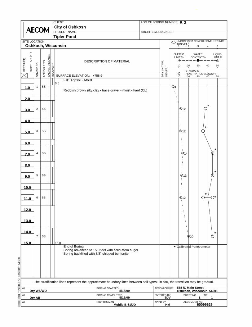
0.6
15.0* Calibrated Penetrometer
1
2
3
4
5
6
7
SS
SS
SS
SS
SS
SS
SS
Fill: Topsoil - Moist
Reddish brown silty clay - trace gravel - moist - hard (CL)
End of BoringBoring advanced to 15.0 feet with solid-stem augerBoring backfilled with 3/8" chipped bentonite
4
12
12
14
13
12
20
*
*
*
*
* *
*
SA
MP
LE D
ISTA
NC
E
SA
MP
LE T
YP
E
PROJECT NAMECity of Oshkosh
SA
MP
LE N
O.
10 20 30 40 50
1 2 3 4 5
LIQUIDLIMIT %
UNCONFINED COMPRESSIVE STRENGTHTONS/FT.2
PLASTICLIMIT %
Tipler Pond
WATERCONTENT %
10 20 30 40 50
DE
PTH
(FT)
RE
CO
VE
RY
LOG OF BORING NUMBER
ELE
VA
TIO
N (F
T)
DESCRIPTION OF MATERIAL
ARCHITECT/ENGINEER
CLIENT
1.0
2.0
3.0
4.0
5.0
6.0
7.0
8.0
9.0
10.0
11.0
12.0
13.0
14.0
15.0
.
SITE LOCATIONOshkosh, Wisconsin
.
DR
Y U
NIT
WT.
LBS
./FT.
3
DRAFT
SURFACE ELEVATION: +758.9
B-3
STANDARDPENETRATION BLOWS/FT.
OS
HK
OS
H T
IPLE
R.G
PJ
STS
.GD
T 5
/21/
09
5/18/09
60099626
SHEET NO.
BORING STARTED
The stratification lines represent the approximate boundary lines between soil types: in situ, the transition may be gradual.
OF
AECOM OFFICE
1
Dry WS/WD
Dry AB BJV
5/18/09
APP'D BYRIG/FOREMANMobile B-61/JD
AECOM JOB NO.
WL
WL
WL
ENTERED BY
HM
1BORING COMPLETED
558 N. Main StreetOshkosh, Wisconsin 54901

0.5
14.5
15.0* Calibrated Penetrometer
1
2
3
4
5
6
7
SS
SS
SS
SS
SS
SS
SS
Fill: Topsoil - Moist
Reddish brown silty clay - trace gravel - moist - hard(CL)
Gray silty sand - trace gravel - moist (SP)
End of BoringBoring advanced to 15.0 feet with solid-stem augerInstalled temporary well at 15.0 feet
3
10
16
14
18
23
37
*
*
*
*
*
*
SA
MP
LE D
ISTA
NC
E
SA
MP
LE T
YP
E
PROJECT NAMECity of Oshkosh
SA
MP
LE N
O.
10 20 30 40 50
1 2 3 4 5
LIQUIDLIMIT %
UNCONFINED COMPRESSIVE STRENGTHTONS/FT.2
PLASTICLIMIT %
Tipler Pond
WATERCONTENT %
10 20 30 40 50
DE
PTH
(FT)
RE
CO
VE
RY
LOG OF BORING NUMBER
ELE
VA
TIO
N (F
T)
DESCRIPTION OF MATERIAL
ARCHITECT/ENGINEER
CLIENT
1.0
2.0
3.0
4.0
5.0
6.0
7.0
8.0
9.0
10.0
11.0
12.0
13.0
14.0
15.0
.
SITE LOCATIONOshkosh, Wisconsin
.
DR
Y U
NIT
WT.
LBS
./FT.
3
DRAFT
SURFACE ELEVATION: +759.9
B-4
STANDARDPENETRATION BLOWS/FT.
OS
HK
OS
H T
IPLE
R.G
PJ
STS
.GD
T 5
/21/
09
+761.9.Well Installation
Top PVC Standpipe
5/18/09
60099626
SHEET NO.
BORING STARTED
The stratification lines represent the approximate boundary lines between soil types: in situ, the transition may be gradual.
OF
AECOM OFFICE
1
Moist WS/WD
13.5 ft. AB BJV
5/18/09
APP'D BYRIG/FOREMANMobile B-61/JD
AECOM JOB NO.
WL
WL
WL
ENTERED BY
HM
1BORING COMPLETED
558 N. Main StreetOshkosh, Wisconsin 54901

1.0
15.0* Calibrated Penetrometer
1
2
3
4
5
6
7
SS
SS
SS
SS
SS
SS
SS
Fill: Topsoil - Moist
Reddish brown silty clay - trace gravel - moist - hard (CL)
End of BoringBoring advanced to 15.0 feet with solid-stem augerBoring backfilled with 3/8" chipped bentonite
4
13
15
14
15
19
25
*
*
*
*
*
SA
MP
LE D
ISTA
NC
E
SA
MP
LE T
YP
E
PROJECT NAMECity of Oshkosh
SA
MP
LE N
O.
10 20 30 40 50
1 2 3 4 5
LIQUIDLIMIT %
UNCONFINED COMPRESSIVE STRENGTHTONS/FT.2
PLASTICLIMIT %
Tipler Pond
WATERCONTENT %
10 20 30 40 50
DE
PTH
(FT)
RE
CO
VE
RY
LOG OF BORING NUMBER
ELE
VA
TIO
N (F
T)
DESCRIPTION OF MATERIAL
ARCHITECT/ENGINEER
CLIENT
1.0
2.0
3.0
4.0
5.0
6.0
7.0
8.0
9.0
10.0
11.0
12.0
13.0
14.0
15.0
.
SITE LOCATIONOshkosh, Wisconsin
.
DR
Y U
NIT
WT.
LBS
./FT.
3
DRAFT
SURFACE ELEVATION: +760.0
B-5
STANDARDPENETRATION BLOWS/FT.
OS
HK
OS
H T
IPLE
R.G
PJ
STS
.GD
T 5
/21/
09
5/18/09
60099626
SHEET NO.
BORING STARTED
The stratification lines represent the approximate boundary lines between soil types: in situ, the transition may be gradual.
OF
AECOM OFFICE
1
Dry WS/WD
Dry AB BJV
5/18/09
APP'D BYRIG/FOREMANMobile B-61/JD
AECOM JOB NO.
WL
WL
WL
ENTERED BY
HM
1BORING COMPLETED
558 N. Main StreetOshkosh, Wisconsin 54901
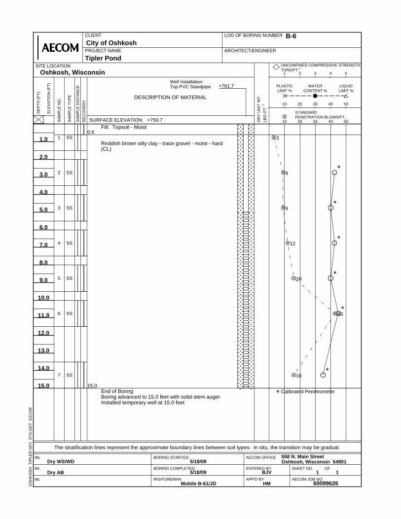
0.6
15.0* Calibrated Penetrometer
1
2
3
4
5
6
7
SS
SS
SS
SS
SS
SS
SS
Fill: Topsoil - Moist
Reddish brown silty clay - trace gravel - moist - hard(CL)
End of BoringBoring advanced to 15.0 feet with solid-stem augerInstalled temporary well at 15.0 feet
3
9
9
12
16
43
16
*
*
*
*
*
*
SA
MP
LE D
ISTA
NC
E
SA
MP
LE T
YP
E
PROJECT NAMECity of Oshkosh
SA
MP
LE N
O.
10 20 30 40 50
1 2 3 4 5
LIQUIDLIMIT %
UNCONFINED COMPRESSIVE STRENGTHTONS/FT.2
PLASTICLIMIT %
Tipler Pond
WATERCONTENT %
10 20 30 40 50
DE
PTH
(FT)
RE
CO
VE
RY
LOG OF BORING NUMBER
ELE
VA
TIO
N (F
T)
DESCRIPTION OF MATERIAL
ARCHITECT/ENGINEER
CLIENT
1.0
2.0
3.0
4.0
5.0
6.0
7.0
8.0
9.0
10.0
11.0
12.0
13.0
14.0
15.0
.
SITE LOCATIONOshkosh, Wisconsin
.
DR
Y U
NIT
WT.
LBS
./FT.
3
DRAFT
SURFACE ELEVATION: +759.7
B-6
STANDARDPENETRATION BLOWS/FT.
OS
HK
OS
H T
IPLE
R.G
PJ
STS
.GD
T 5
/21/
09
+761.7.Well Installation
Top PVC Standpipe
5/18/09
60099626
SHEET NO.
BORING STARTED
The stratification lines represent the approximate boundary lines between soil types: in situ, the transition may be gradual.
OF
AECOM OFFICE
1
Dry WS/WD
Dry AB BJV
5/18/09
APP'D BYRIG/FOREMANMobile B-61/JD
AECOM JOB NO.
WL
WL
WL
ENTERED BY
HM
1BORING COMPLETED
558 N. Main StreetOshkosh, Wisconsin 54901

0.50.8
12.0* Calibrated Penetrometer12.0
1
2
3
4
5
6
SS
SS
SS
SS
SS
SS
Concrete
Fill: Base course
Reddish brown silty clay - trace gravel - moist - very stiff tohard (CL)
End of BoringBoring advanced to 12.0 feet with solid-stem augerBoring backfilled with 3/8" chipped bentonite
7
9
9
13
14
22
*
*
*
*
*
*
SA
MP
LE D
ISTA
NC
E
SA
MP
LE T
YP
E
PROJECT NAMECity of Oshkosh
SA
MP
LE N
O.
10 20 30 40 50
1 2 3 4 5
LIQUIDLIMIT %
UNCONFINED COMPRESSIVE STRENGTHTONS/FT.2
PLASTICLIMIT %
Tipler Pond
WATERCONTENT %
10 20 30 40 50
DE
PTH
(FT)
RE
CO
VE
RY
LOG OF BORING NUMBER
ELE
VA
TIO
N (F
T)
DESCRIPTION OF MATERIAL
ARCHITECT/ENGINEER
CLIENT
1.0
2.0
3.0
4.0
5.0
6.0
7.0
8.0
9.0
10.0
11.0
12.0
.
SITE LOCATIONOshkosh, Wisconsin
.
DR
Y U
NIT
WT.
LBS
./FT.
3
DRAFT
SURFACE ELEVATION: +760.6
B-7
STANDARDPENETRATION BLOWS/FT.
OS
HK
OS
H T
IPLE
R.G
PJ
STS
.GD
T 5
/21/
09
5/19/09
60099626
SHEET NO.
BORING STARTED
The stratification lines represent the approximate boundary lines between soil types: in situ, the transition may be gradual.
OF
AECOM OFFICE
1
Dry WS/WD
Dry AB BJV
5/19/09
APP'D BYRIG/FOREMANMobile B-61/JD
AECOM JOB NO.
WL
WL
WL
ENTERED BY
HM
1BORING COMPLETED
558 N. Main StreetOshkosh, Wisconsin 54901

3.5
12.0* Calibrated Penetrometer12.0
1
2
3
4
5
6
SS
SS
SS
SS
SS
SS
Fill: Brown silty clay - some sand
Reddish brown silty clay - trace gravel - moist - very stiff (CL)
End of BoringBoring advanced to 12.0 feet with solid-stem augerBoring backfilled with 3/8" chipped bentonite
3
6
12
8
15
19
*
*
*
*
*
*
SA
MP
LE D
ISTA
NC
E
SA
MP
LE T
YP
E
PROJECT NAMECity of Oshkosh
SA
MP
LE N
O.
10 20 30 40 50
1 2 3 4 5
LIQUIDLIMIT %
UNCONFINED COMPRESSIVE STRENGTHTONS/FT.2
PLASTICLIMIT %
Tipler Pond
WATERCONTENT %
10 20 30 40 50
DE
PTH
(FT)
RE
CO
VE
RY
LOG OF BORING NUMBER
ELE
VA
TIO
N (F
T)
DESCRIPTION OF MATERIAL
ARCHITECT/ENGINEER
CLIENT
1.0
2.0
3.0
4.0
5.0
6.0
7.0
8.0
9.0
10.0
11.0
12.0
.
SITE LOCATIONOshkosh, Wisconsin
.
DR
Y U
NIT
WT.
LBS
./FT.
3
DRAFT
SURFACE ELEVATION: +760.9
B-8
STANDARDPENETRATION BLOWS/FT.
OS
HK
OS
H T
IPLE
R.G
PJ
STS
.GD
T 5
/21/
09
5/19/09
60099626
SHEET NO.
BORING STARTED
The stratification lines represent the approximate boundary lines between soil types: in situ, the transition may be gradual.
OF
AECOM OFFICE
1
8.0 ft. WS
8.3 ft. AB BJV
5/19/09
APP'D BYRIG/FOREMANMobile B-61/JD
AECOM JOB NO.
WL
WL
WL
ENTERED BY
HM
1BORING COMPLETED
558 N. Main StreetOshkosh, Wisconsin 54901

1.5
10.0
11.0* Calibrated Penetrometer11.0
1
2
3
4
5
6
SS
SS
SS
SS
SS
SS
Fill: Topsoil - Moist
Reddish brown silty clay - trace gravel - moist - very stiff (CL)
Gray silty sand - trace gravel - moist - very dense (SP)
End of BoringBoring advanced to 11.0 feet with solid-stem augerBoring backfilled with 3/8" chipped bentonite
4
9
13
10
54
51/6"
*
*
*
SA
MP
LE D
ISTA
NC
E
SA
MP
LE T
YP
E
PROJECT NAMECity of Oshkosh
SA
MP
LE N
O.
10 20 30 40 50
1 2 3 4 5
LIQUIDLIMIT %
UNCONFINED COMPRESSIVE STRENGTHTONS/FT.2
PLASTICLIMIT %
Tipler Pond
WATERCONTENT %
10 20 30 40 50
DE
PTH
(FT)
RE
CO
VE
RY
LOG OF BORING NUMBER
ELE
VA
TIO
N (F
T)
DESCRIPTION OF MATERIAL
ARCHITECT/ENGINEER
CLIENT
1.0
2.0
3.0
4.0
5.0
6.0
7.0
8.0
9.0
10.0
11.0
.
SITE LOCATIONOshkosh, Wisconsin
.
DR
Y U
NIT
WT.
LBS
./FT.
3
DRAFT
SURFACE ELEVATION: +762.3
B-9
STANDARDPENETRATION BLOWS/FT.
OS
HK
OS
H T
IPLE
R.G
PJ
STS
.GD
T 5
/21/
09
5/19/09
60099626
SHEET NO.
BORING STARTED
The stratification lines represent the approximate boundary lines between soil types: in situ, the transition may be gradual.
OF
AECOM OFFICE
1
Dry WS/WD
Dry AB BJV
5/19/09
APP'D BYRIG/FOREMANMobile B-61/JD
AECOM JOB NO.
WL
WL
WL
ENTERED BY
HM
1BORING COMPLETED
558 N. Main StreetOshkosh, Wisconsin 54901

1.5
12.0* Calibrated Penetrometer12.0
1
2
3
4
5
6
SS
SS
SS
SS
SS
SS
Fill: Topsoil - Moist
Reddish brown silty clay - trace gravel - moist - hard (CL)
End of BoringBoring advanced to 12.0 feet with solid-stem augerBoring backfilled with 3/8" chipped bentonite
4
7
11
13
18
16
* *
*
*
*
*
SA
MP
LE D
ISTA
NC
E
SA
MP
LE T
YP
E
PROJECT NAMECity of Oshkosh
SA
MP
LE N
O.
10 20 30 40 50
1 2 3 4 5
LIQUIDLIMIT %
UNCONFINED COMPRESSIVE STRENGTHTONS/FT.2
PLASTICLIMIT %
Tipler Pond
WATERCONTENT %
10 20 30 40 50
DE
PTH
(FT)
RE
CO
VE
RY
LOG OF BORING NUMBER
ELE
VA
TIO
N (F
T)
DESCRIPTION OF MATERIAL
ARCHITECT/ENGINEER
CLIENT
1.0
2.0
3.0
4.0
5.0
6.0
7.0
8.0
9.0
10.0
11.0
12.0
.
SITE LOCATIONOshkosh, Wisconsin
.
DR
Y U
NIT
WT.
LBS
./FT.
3
DRAFT
SURFACE ELEVATION: +762.1
B-10
STANDARDPENETRATION BLOWS/FT.
OS
HK
OS
H T
IPLE
R.G
PJ
STS
.GD
T 5
/21/
09
5/19/09
60099626
SHEET NO.
BORING STARTED
The stratification lines represent the approximate boundary lines between soil types: in situ, the transition may be gradual.
OF
AECOM OFFICE
1
Dry WS/WD
Dry AB BJV
5/19/09
APP'D BYRIG/FOREMANMobile B-61/JD
AECOM JOB NO.
WL
WL
WL
ENTERED BY
HM
1BORING COMPLETED
558 N. Main StreetOshkosh, Wisconsin 54901
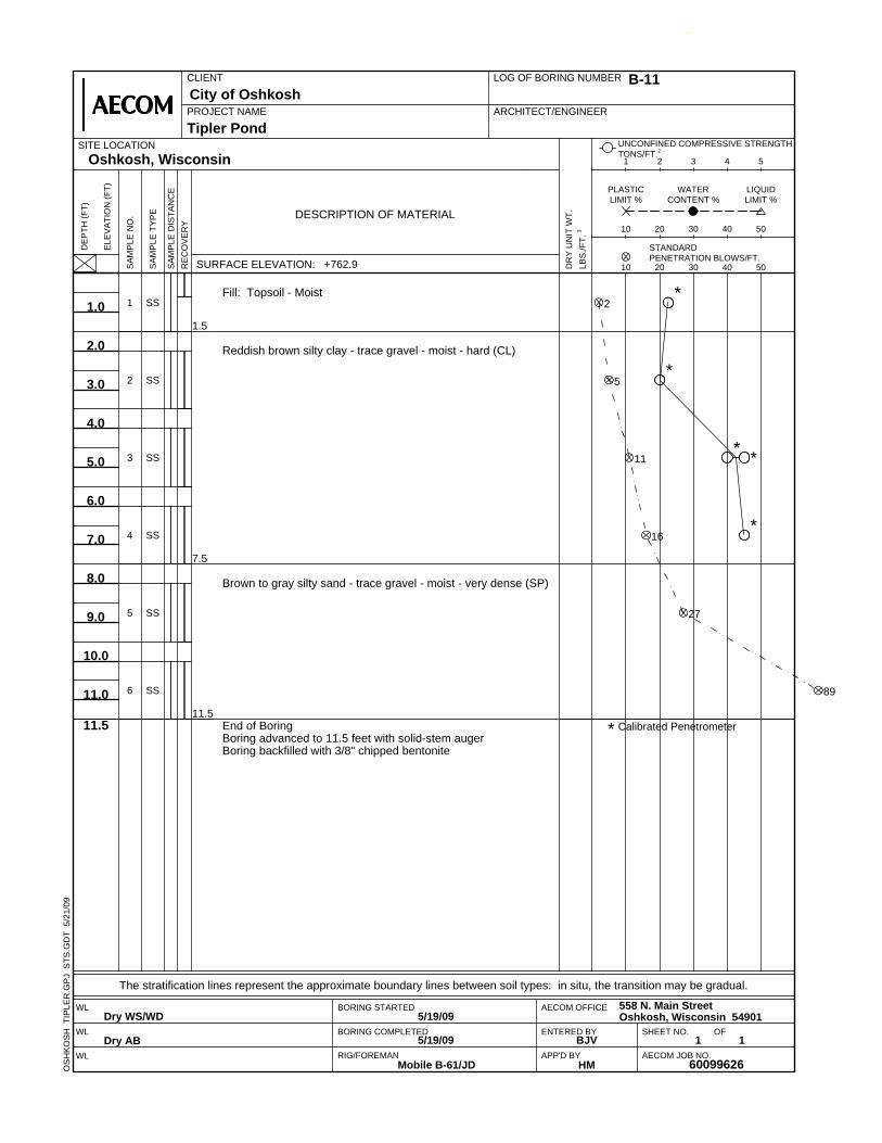
1.5
7.5
11.5* Calibrated Penetrometer11.5
1
2
3
4
5
6
SS
SS
SS
SS
SS
SS
Fill: Topsoil - Moist
Reddish brown silty clay - trace gravel - moist - hard (CL)
Brown to gray silty sand - trace gravel - moist - very dense (SP)
End of BoringBoring advanced to 11.5 feet with solid-stem augerBoring backfilled with 3/8" chipped bentonite
2
5
11
16
27
89
*
*
* *
*
SA
MP
LE D
ISTA
NC
E
SA
MP
LE T
YP
E
PROJECT NAMECity of Oshkosh
SA
MP
LE N
O.
10 20 30 40 50
1 2 3 4 5
LIQUIDLIMIT %
UNCONFINED COMPRESSIVE STRENGTHTONS/FT.2
PLASTICLIMIT %
Tipler Pond
WATERCONTENT %
10 20 30 40 50
DE
PTH
(FT)
RE
CO
VE
RY
LOG OF BORING NUMBER
ELE
VA
TIO
N (F
T)
DESCRIPTION OF MATERIAL
ARCHITECT/ENGINEER
CLIENT
1.0
2.0
3.0
4.0
5.0
6.0
7.0
8.0
9.0
10.0
11.0
.
SITE LOCATIONOshkosh, Wisconsin
.
DR
Y U
NIT
WT.
LBS
./FT.
3
DRAFT
SURFACE ELEVATION: +762.9
B-11
STANDARDPENETRATION BLOWS/FT.
OS
HK
OS
H T
IPLE
R.G
PJ
STS
.GD
T 5
/21/
09
5/19/09
60099626
SHEET NO.
BORING STARTED
The stratification lines represent the approximate boundary lines between soil types: in situ, the transition may be gradual.
OF
AECOM OFFICE
1
Dry WS/WD
Dry AB BJV
5/19/09
APP'D BYRIG/FOREMANMobile B-61/JD
AECOM JOB NO.
WL
WL
WL
ENTERED BY
HM
1BORING COMPLETED
558 N. Main StreetOshkosh, Wisconsin 54901
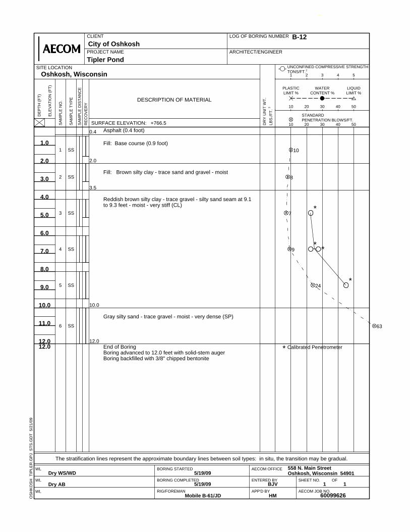
0.4
2.0
3.5
10.0
12.0* Calibrated Penetrometer12.0
1
2
3
4
5
6
SS
SS
SS
SS
SS
SS
Asphalt (0.4 foot)
Fill: Base course (0.9 foot)
Fill: Brown silty clay - trace sand and gravel - moist
Reddish brown silty clay - trace gravel - silty sand seam at 9.1to 9.3 feet - moist - very stiff (CL)
Gray silty sand - trace gravel - moist - very dense (SP)
End of BoringBoring advanced to 12.0 feet with solid-stem augerBoring backfilled with 3/8" chipped bentonite
10
8
7
9
24
63
*
* *
*
SA
MP
LE D
ISTA
NC
E
SA
MP
LE T
YP
E
PROJECT NAMECity of Oshkosh
SA
MP
LE N
O.
10 20 30 40 50
1 2 3 4 5
LIQUIDLIMIT %
UNCONFINED COMPRESSIVE STRENGTHTONS/FT.2
PLASTICLIMIT %
Tipler Pond
WATERCONTENT %
10 20 30 40 50
DE
PTH
(FT)
RE
CO
VE
RY
LOG OF BORING NUMBER
ELE
VA
TIO
N (F
T)
DESCRIPTION OF MATERIAL
ARCHITECT/ENGINEER
CLIENT
1.0
2.0
3.0
4.0
5.0
6.0
7.0
8.0
9.0
10.0
11.0
12.0
.
SITE LOCATIONOshkosh, Wisconsin
.
DR
Y U
NIT
WT.
LBS
./FT.
3
DRAFT
SURFACE ELEVATION: +766.5
B-12
STANDARDPENETRATION BLOWS/FT.
OS
HK
OS
H T
IPLE
R.G
PJ
STS
.GD
T 5
/21/
09
5/19/09
60099626
SHEET NO.
BORING STARTED
The stratification lines represent the approximate boundary lines between soil types: in situ, the transition may be gradual.
OF
AECOM OFFICE
1
Dry WS/WD
Dry AB BJV
5/19/09
APP'D BYRIG/FOREMANMobile B-61/JD
AECOM JOB NO.
WL
WL
WL
ENTERED BY
HM
1BORING COMPLETED
558 N. Main StreetOshkosh, Wisconsin 54901


AECOM
May 2009
Appendix B AECOM General Notes
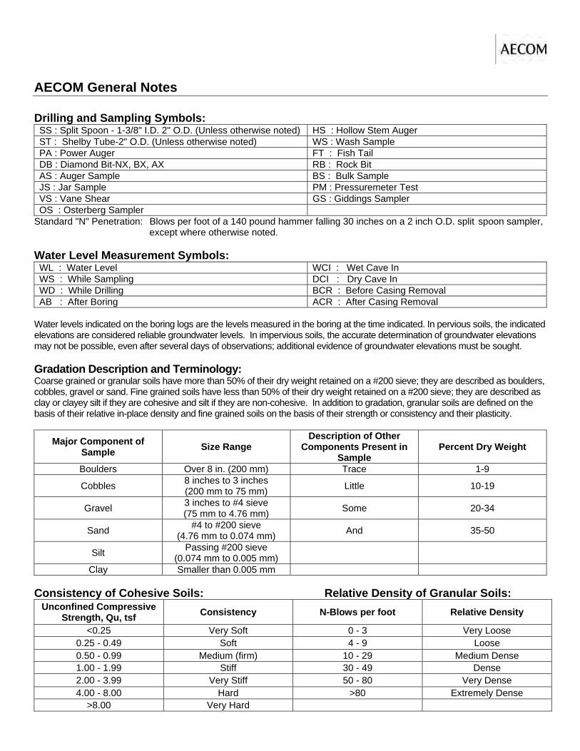
AECOM General Notes Drilling and Sampling Symbols: SS : Split Spoon - 1-3/8" I.D. 2" O.D. (Unless otherwise noted) HS : Hollow Stem Auger ST : Shelby Tube-2" O.D. (Unless otherwise noted) WS : Wash Sample PA : Power Auger FT : Fish Tail DB : Diamond Bit-NX, BX, AX RB : Rock Bit AS : Auger Sample BS : Bulk Sample JS : Jar Sample PM : Pressuremeter Test VS : Vane Shear GS : Giddings Sampler OS : Osterberg Sampler
Standard "N" Penetration: Blows per foot of a 140 pound hammer falling 30 inches on a 2 inch O.D. split spoon sampler, except where otherwise noted. Water Level Measurement Symbols: WL : Water Level WCI : Wet Cave In WS : While Sampling DCI : Dry Cave In WD : While Drilling BCR : Before Casing Removal AB : After Boring ACR : After Casing Removal
Water levels indicated on the boring logs are the levels measured in the boring at the time indicated. In pervious soils, the indicated elevations are considered reliable groundwater levels. In impervious soils, the accurate determination of groundwater elevations may not be possible, even after several days of observations; additional evidence of groundwater elevations must be sought. Gradation Description and Terminology: Coarse grained or granular soils have more than 50% of their dry weight retained on a #200 sieve; they are described as boulders, cobbles, gravel or sand. Fine grained soils have less than 50% of their dry weight retained on a #200 sieve; they are described as clay or clayey silt if they are cohesive and silt if they are non-cohesive. In addition to gradation, granular soils are defined on the basis of their relative in-place density and fine grained soils on the basis of their strength or consistency and their plasticity.
Major Component of Sample Size Range
Description of Other Components Present in
Sample Percent Dry Weight
Boulders Over 8 in. (200 mm) Trace 1-9
Cobbles 8 inches to 3 inches (200 mm to 75 mm) Little 10-19
Gravel 3 inches to #4 sieve (75 mm to 4.76 mm) Some 20-34
Sand #4 to #200 sieve (4.76 mm to 0.074 mm) And 35-50
Silt Passing #200 sieve (0.074 mm to 0.005 mm)
Clay Smaller than 0.005 mm Consistency of Cohesive Soils: Relative Density of Granular Soils:
Unconfined Compressive Strength, Qu, tsf Consistency N-Blows per foot Relative Density
<0.25 Very Soft 0 - 3 Very Loose 0.25 - 0.49 Soft 4 - 9 Loose 0.50 - 0.99 Medium (firm) 10 - 29 Medium Dense 1.00 - 1.99 Stiff 30 - 49 Dense 2.00 - 3.99 Very Stiff 50 - 80 Very Dense 4.00 - 8.00 Hard >80 Extremely Dense
>8.00 Very Hard

AECOM
May 2009
Appendix C AECOM Field and Laboratory Procedures

AECOM Field and Laboratory Procedures Field Sampling Procedures Auger Sampling (AS) In this procedure, soil samples are collected from cuttings off of the auger flights as they are removed from the ground. Such samples provide a general indication of subsurface conditions; however, they do not provide undisturbed samples, nor do they provide samples from discrete depths. Split-Barrel Sampling (SS) - (ASTM Standard D-1586-99) In the split-barrel sampling procedure, a 2-inch O.D. split barrel sampler is driven into the soil a distance of 18 inches by means of a 140-pound hammer falling 30 inches. The value of the Standard Penetration Resistance is obtained by counting the number of blows of the hammer over the final 12 inches of driving. This value provides a qualitative indication of the in-place relative density of cohesionless soils. The indication is qualitative only, however, since many factors can significantly affect the Standard Penetration Resistance Value, and direct correlation of results obtained by drill crews using different rigs, drilling procedures, and hammer-rod-spoon assemblies should not be made. A portion of the recovered sample is placed in a sample jar and returned to the laboratory for further analysis and testing. Shelby Tube Sampling Procedure (ST) - ASTM Standard D-1587-94 In the Shelby tube sampling procedure, a thin-walled steel seamless tube with a sharp cutting edge is pushed hydraulically into the soil and a relatively undisturbed sample is obtained. This procedure is generally employed in cohesive soils. The tubes are identified, sealed and carefully handled in the field to avoid excessive disturbance and are returned to the laboratory for extrusion and further analysis and testing. Giddings Sampler (GS) This type of sampling device consists of 5-foot sections of thin-wall tubing which are capable of retrieving continuous columns of soil in 5-foot maximum increments. Because of a continuous slot in the sampling tubes, the sampler allows field determination of stratification boundaries and containerization of soil samples from any sampling depth within the 5-foot interval.

AECOM
May 2009
Appendix D AECOM Soil Classification System Chart

AECOM Soil Classification System (1)
1. See AECOM General Notes for component gradation terminology, consistency of cohesive soils and relative
density of granular soils. 2. Reference: Unified Soil Classification Systems 3. Borderline classifications, used for soils possessing characteristics of two groups, are designated by
combinations of group symbols. For example: GW-GC, well-graded gravel-sand mixture with clay binder.