


Languages
Pages
Legal


THE IRAPÉ DAM ANDHYDROELECTRIC PROJECT
This paper was written by Brasil Pinheiro Machado based on papers indicated in the references.Some figures and the technical features were based from documents furnished by Waldaisy S. Abreu Sifuentes from Leme.

Main Brazilian Dams III
194
THE IRAPÉ DAM ANDHYDROELECTRIC PROJECT
1. INTRODUCTIONThe Irapé Project, is a 360 MW hydroelectric project,
built in the upper reach of the Jequitinhonha River, in theState of Minas Gerais, Brazil. The main purpose of theproject, besides local power generation, is to create alarge reservoir to regulate the river flow for a series ofdownstream hydro-projects programmed to be built inthe near future and including the already built 450-MWItapebi Project. The reservoir, with a total volume of6 billion cubic meters and flooding an area of 137 km2, iscreated by an earth-core rockfill dam, 208-m high, thehighest in Brazil.
The Project is owned and operated by CEMIG -Companhia Energética de Minas Gerais, the power utilityfor the State of Minas Gerais. The Project was built fromMay 2002 to August 2005, with a strict and very tightschedule of 40 months from start of site activities to initialpower generation. It was designed by a consortium oftwo Brazilian engineering firms, INTERTECHNEConsultores and LEME Engenharia acting as engineersin an EPC joint-venture led by ANDRADE GUTIERREZand including construction companies ODEBRECHT,HOCHTIEF and IVAI and with Voith-Siemens Hydro for
equipment supply. CEMIG technical team acted asOwner's Engineer and managed as well the administrativeand commercial issues of the realisation of the Project.A general view of the Project is depicted in Photo 1.
2. BACKGROUND
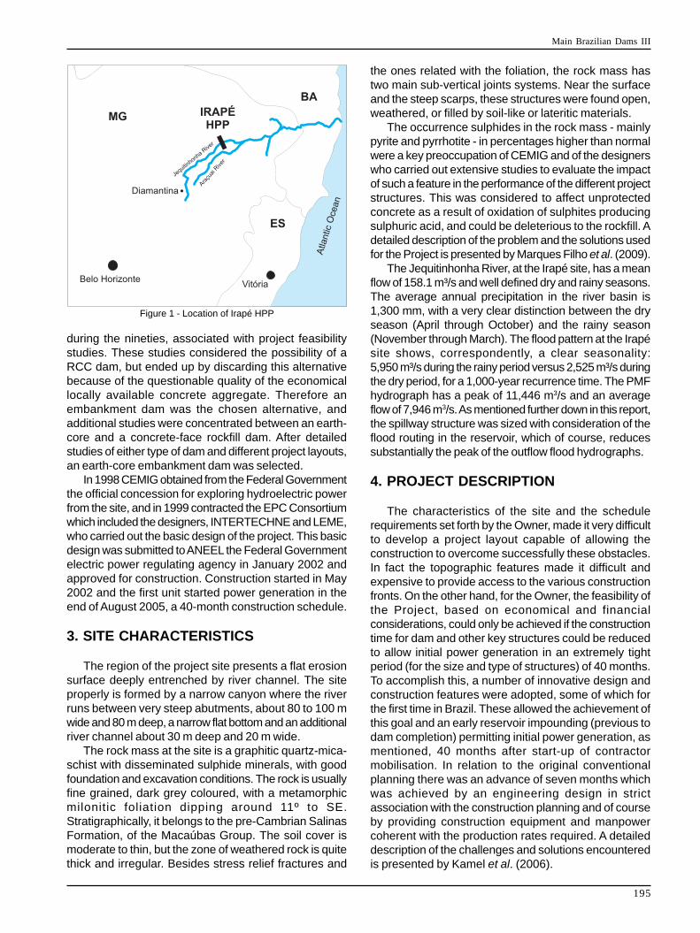
The Jequitinhonha River Basin is located mainly inthe Northern part of Brazilian State of Minas Gerais witha minor part in the State of Bahia, as illustrated in Figure1. The river basin was initially surveyed for itshydroelectric resources during the sixties as part of themajor Brazilian Inventory of Hydroelectric Resources,covering the South-Central area of the country. Thesestudies identified 20 feasible sites for power projects inthe basin. A later study, carried out between 1984 and1987, revised the conclusions of the previous survey andreduced the number of feasible sites to 14, in which theIrapé site was identified, and the project considered as amajor upstream reservoir for regulating the river flowsbesides local electric power generation.
Comprehensive site topographical, geological andhydrological investigations were carried out by CEMIG
Photo 1 - General View of Irapé Hydroelectric Project
Main Brazilian Dams III
195
Figure 1 - Location of Irapé HPP
during the nineties, associated with project feasibilitystudies. These studies considered the possibility of aRCC dam, but ended up by discarding this alternativebecause of the questionable quality of the economicallocally available concrete aggregate. Therefore anembankment dam was the chosen alternative, andadditional studies were concentrated between an earth-core and a concrete-face rockfill dam. After detailedstudies of either type of dam and different project layouts,an earth-core embankment dam was selected.
In 1998 CEMIG obtained from the Federal Governmentthe official concession for exploring hydroelectric powerfrom the site, and in 1999 contracted the EPC Consortiumwhich included the designers, INTERTECHNE and LEME,who carried out the basic design of the project. This basicdesign was submitted to ANEEL the Federal Governmentelectric power regulating agency in January 2002 andapproved for construction. Construction started in May2002 and the first unit started power generation in theend of August 2005, a 40-month construction schedule.
3. SITE CHARACTERISTICS
The region of the project site presents a flat erosionsurface deeply entrenched by river channel. The siteproperly is formed by a narrow canyon where the riverruns between very steep abutments, about 80 to 100 mwide and 80 m deep, a narrow flat bottom and an additionalriver channel about 30 m deep and 20 m wide.
The rock mass at the site is a graphitic quartz-mica-schist with disseminated sulphide minerals, with goodfoundation and excavation conditions. The rock is usuallyfine grained, dark grey coloured, with a metamorphicmilonitic foliation dipping around 11º to SE.Stratigraphically, it belongs to the pre-Cambrian SalinasFormation, of the Macaúbas Group. The soil cover ismoderate to thin, but the zone of weathered rock is quitethick and irregular. Besides stress relief fractures and
the ones related with the foliation, the rock mass hastwo main sub-vertical joints systems. Near the surfaceand the steep scarps, these structures were found open,weathered, or filled by soil-like or lateritic materials.
The occurrence sulphides in the rock mass - mainlypyrite and pyrrhotite - in percentages higher than normalwere a key preoccupation of CEMIG and of the designerswho carried out extensive studies to evaluate the impactof such a feature in the performance of the different projectstructures. This was considered to affect unprotectedconcrete as a result of oxidation of sulphites producingsulphuric acid, and could be deleterious to the rockfill. Adetailed description of the problem and the solutions usedfor the Project is presented by Marques Filho et al. (2009).
The Jequitinhonha River, at the Irapé site, has a meanflow of 158.1 m³/s and well defined dry and rainy seasons.The average annual precipitation in the river basin is1,300 mm, with a very clear distinction between the dryseason (April through October) and the rainy season(November through March). The flood pattern at the Irapésite shows, correspondently, a clear seasonality:5,950 m³/s during the rainy period versus 2,525 m³/s duringthe dry period, for a 1,000-year recurrence time. The PMFhydrograph has a peak of 11,446 m3/s and an averageflow of 7,946 m3/s. As mentioned further down in this report,the spillway structure was sized with consideration of theflood routing in the reservoir, which of course, reducessubstantially the peak of the outflow flood hydrographs.
4. PROJECT DESCRIPTION
The characteristics of the site and the schedulerequirements set forth by the Owner, made it very difficultto develop a project layout capable of allowing theconstruction to overcome successfully these obstacles.In fact the topographic features made it difficult andexpensive to provide access to the various constructionfronts. On the other hand, for the Owner, the feasibility ofthe Project, based on economical and financialconsiderations, could only be achieved if the constructiontime for dam and other key structures could be reducedto allow initial power generation in an extremely tightperiod (for the size and type of structures) of 40 months.To accomplish this, a number of innovative design andconstruction features were adopted, some of which forthe first time in Brazil. These allowed the achievement ofthis goal and an early reservoir impounding (previous todam completion) permitting initial power generation, asmentioned, 40 months after start-up of contractormobilisation. In relation to the original conventionalplanning there was an advance of seven months whichwas achieved by an engineering design in strictassociation with the construction planning and of courseby providing construction equipment and manpowercoherent with the production rates required. A detaileddescription of the challenges and solutions encounteredis presented by Kamel et al. (2006).

Main Brazilian Dams III
196
The Project layout is depicted in Figure 2.As seen in this figure, the Project is developed across
a rather tight river curve which has its inner side in theleft margin, and ending in an almost 90º angle to theright of the incoming stretch of the river. The dam axis isplaced upstream of the "vertex" of the river curve in asection which was considered, topographically andgeologically best fitted for it. The power waterways andthe spillway structure are routed in the left margin,bypassing the dam, but with features and locationsespecially designed to reduce construction quantities andto expedite construction activities.
4.1. River DiversionRiver diversion for construction was done through
two diversion tunnels designed with a cofferdamheight compatible with a 50-year recurrence period duringthe first wet period and subsequently for higherfloods and different crest dam elevations. The tunnelswere built on the right bank, contrary to what seemedto be the logic design solution, because thereexisted a public road on the right margin of the river,from which access to the initial construction areawould be easier and faster. This impliedlonger diversion tunnels as compared with thealternative location in the left abutment, but allowedachievement of river diversion 11 months afterinitial construction mobilisation, that is three monthsbefore originally scheduled.
One of the tunnels was designed and builtwith its entrance at a higher elevation than the other one,and without a flow control structure. This tunnel was1060 m long. The other tunnel, was 1230 m long, had anentrance elevation lower than the other and had anunderground gate controlled structure, accessible by avertical shaft. This concept of one of the tunnels with ahigher entrance without control structure is now a commonpractice in Brazil and is intended to save inconcrete, equipment and of course in time because thelogic is that it is closed with a soil embankment at thebeginning of the dry season when the lower tunnel iscapable to handle the river flows. This concept was firstused at the Segredo Powerplant in the Iguaçu River, in1992.
The diversion tunnels had a mushroom rectangularsection, 13,0 m high by 13.2 m width, excavatedin a crown and bench scheme. They had no liningexcept for localised shotcrete and rockboltingtreatments.
4.2. DamThe Irapé Dam is an earth-core rockfill dam, 208 m
high, the highest in Brazil. Its crest elevation is 515.5 mand the crest length 551 m. The upstream slope is1: 1.5 up to El 484.0 and 1: 1.3 in the remainder height.The downstream slope is 1: 1.3 between the climbingroad stretches, averaging 1: 1.5. The maximum crosssection of the dam is shown on Figure 3.
Figure 2 - General Layout of the Structures of the Irapé Project
Main Brazilian Dams III
197
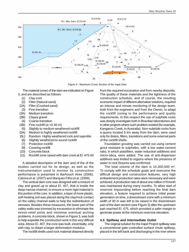
The material zones of the dam are indicated on Figure3, and are described as follows:
(1) Clay core(2) Filter (Natural sand)
(2A) Filter (Crushed sand)(3) Fine transition
(3A) Medium transition(3B) Clayey gravel
(4) Coarse transition(4B) Fine rockfill (Ø <0.40 m)
(5) Slightly to medium weathered rockfill(5A) Medium to highly weathered rockfill(5L) Random. Highly weathered rock and saprolite(6) Slightly weathered to sound rockfill(7) Protection rockfill(9) Covering rockfill
(10) Concrete block(11) Rockfill zone raised with dam crest at El. 475.00
A detailed description of the dam and of the of thestudies carried out for its design, as well as theinstrumentation used to monitor its constructionperformance is presented in Barhouch Aires (2006),Calcina et al. (2007) and Marques Filho et al. (2009).
The vertical dam core was designed with a mixture ofclay and gravel up to about El. 407, that is inside thedeep narrow channel, to ensure a more rigid material inthis portion of the core. In addition, a layer of more plastic,self-healing soil was placed along the clay/rock contacton the valley channel walls to help the redistribution ofstresses. Besides these measures, the lower part of thevalley walls was trimmed by excavation to eliminate thestress-relief joints and minimise eventual archingproblems. A concrete block, shown in Figure 3, was builtto help expedite the construction work in this very difficultarea. Above El. 407, the core was built, essentially, onlywith clay, to obtain a larger deformation modulus.
The rockfill shells used rock material obtained directly
Figure 3 - Maximum Cross Section of the Irapé Dam
from the required excavation and from nearby deposits.The quality of these materials and the tightness of theconstruction schedule, and of course, the resultingeconomic impact of different alternative solutions, requiredan intense and minute monitoring of the design team,both from the engineers and from the Owner, to adaptthe rockfill zoning to the performance and qualityrequirements. In this respect the use of sulphide rockswas deeply investigate both in Brazilian laboratories andin other projects where such problem existed (for example,Kangaroo Creek, in Australia). Non-sulphide rocks froma quarry located 5 km away from the dam, were usedonly for drains, filters, transitions and some external partsof the rockfill shells.
Foundation grouting was carried out using cementgrout resistant to sulphides, with a low water-cementratio, in which plastifiers, water reduction additives andmicro-silica, were added. The use of anti-dispersionadditives was limited to regions where the presence ofwater in rock fissures was confirmed.
The total volume of the dam is 10,300,000 m3.To comply with the schedule goals and overcome thedifficult design and construction features, very highembankment production rates were necessary and wereachieved. A production rate of about one million m3/monthwas maintained during many months. To allow start ofreservoir impounding before reaching the final damelevation, a feature required to achieve initial powergeneration on time, a downstream zone with a minimumwidth of 30 m was left to be raised in the downstreampart of the dam section (see Figure 3) after the upstreampart reached El. 475, which provided a safer margin togenerate power at the minimum reservoir elevation.
4.3. Spillway and Intermediate OutletThe original solution for the Irapé Project spillway was
a conventional gate-controlled surface chute spillway,placed in the left bank and discharging in the river where
Main Brazilian Dams III
198
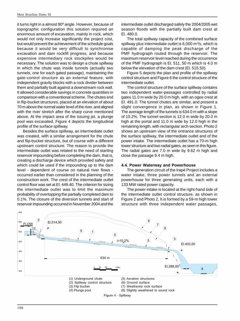
it turns right in a almost 90º angle. However, because oftopographic configuration this solution required anenormous amount of excavation, mainly in rock, whichwould not only increase significantly the project cost,but would prevent the achievement of the schedule goalsbecause it would be very difficult to synchroniseexcavation and dam rockfill progress, and becauseexpensive intermediary rock stockpiles would benecessary. The solution was to design a chute spillwayin which the chute was inside tunnels (actually twotunnels, one for each gated passage), maintaining thegate-control structure as an external feature, withindependent gravity blocks with a rock divider betweenthem and partially built against a downstream rock wall.It allowed considerable savings in concrete quantities incomparison with a conventional scheme. The chutes endin flip-bucket structures, placed at an elevation of about70 m above the normal water level of the river, and alignedwith the river stretch after the sharp curve mentionedabove. At the impact area of the issuing jet, a plungepool was excavated. Figure 4 depicts the longitudinalprofile of the surface spillway.
Besides the surface spillway, an intermediate outletwas created, with a similar arrangement for the chuteand flip-bucket structure, but of course with a differentupstream control structure. The reason to provide theintermediate outlet was related to the need of startingreservoir impounding before completing the dam, that is,creating a discharge device which provided safety andwhich could be used if the impounding up to the damlevel - dependent of course on natural river flows -occurred earlier than considered in the planning of theconstruction work. The crest of the intermediate outletcontrol floor was set at El. 449.40. The criterion for sizingthe intermediate outlet was to limit the maximumprobability of overtopping the partially completed dam to0.1%. The closure of the diversion tunnels and start ofreservoir impounding occurred in November 2004 and the
Figure 4 - Spillway
(1) Underground chute(2) Spillway control structure(3) Flip bucket(4) Plunge pool
(5) Aeration structures(6) Ground surface(7) Weathered rock surface(8) Slightly weathered to sound rock
intermediate outlet discharged safely the 2004/2005 wetseason floods with the partially built dam crest atEl. 480.0.
The total spillway capacity of the combined surfacespillway plus intermediate outlet is 6,000 m3/s, which iscapable of damping the peak discharge of thePMF hydrograph routed through the reservoir. Themaximum reservoir level reached during the occurrenceof the PMF hydrograph is El. 511, 50 m which is 4.0 mbelow the elevation of the dam crest (El. 515.50).
Figure 5 depicts the plan and profile of the spillwaycontrol structure and Figure 6 the control structure of theintermediate outlet.
The control structure of the surface spillway containstwo independent water-passages controlled by radialgates 11.0 m wide by 20.0 m high, with an ogee crest atEl. 491.0. The tunnel chutes are similar, and present aslight convergence in plan, as shown in Figure 1.The average length of the tunnels is 634.0 m with a slopeof 10.2%. The tunnel section is 12.0 m wide by 20.0 mhigh at the portal and 11.0 m wide by 12.0 high in theremaining length, with rectangular arch section. Photo 2shows an upstream view of the entrance structures ofthe surface spillway, the intermediate outlet and of thepower intake. The intermediate outlet has a 70-m hightower structure and two radial gates, as seen in this figure.The radial gates are 7.0 m wide by 9.62 m high andclose the passage 9.4 m high.
4.4. Power Waterway and PowerhouseThe generation circuit of the Irapé Project includes a
water intake, three power tunnels and an externalpowerhouse for three generating units, each with a133 MW rated power capacity.
The power intake is located at the right-hand side ofthe intermediate outlet control structure, as shown inFigure 2 and Photo 2. It is formed by a 59-m high towerstructure with three independent water passages,

Main Brazilian Dams III
199
Figure 5 - Spillway Control Structure
Figure 6 - Intermediate Outlet - Control Structure
Photo 2 - Upstream View of the Control Structures of Spillway,Intermediate Outlet and Power Intake.
equipped with emergency and service gates, with a waterflow section 3.8 m wide by 5.1 m high.
The three independent power tunnels have a firstportion as vertical shafts, 57 m long, followed by a 20 mcurve and a 328 m long straight segment, with a slope of12% descending into the external powerhouse. The initial404 m of each penstock tunnel is lined with unreinforcedconcrete, 40 cm thick, with an internal diameter of4.6 m. The remaining length of about 110 m is steel lined
with an internal diameter of 3.8 m. The average total lengthof each penstock is 453 m. They daylight at a distance8.5 m upstream of the centreline of the generating units.The criterion used for the hydraulic design of the waterwaywas based on the requirement of obtaining a net head forpower generation of 158.50 m. At the initial section ofthe steel lined portion of the penstocks a grouting curtainand a drainage curtain were provided. In addition adrainage gallery with drainage holes connecting to thesteel lined portion was provided as well.
The external powerhouse is a conventional concretestructure housing three vertical Francis turbine drivengenerating units. The service electrical and mechanicalgalleries are placed downstream of the units. Thesegalleries house the main mechanical and electricalauxiliary and control equipment. The service bay is locatedat the right-hand side of the powerhouse in a structurewhich also contains the drainage pits and the auxiliaryservice transformers. Figure 7 shows a section of thepowerhouse.
Photo 3 shows a general view of the powerhouse area.

Main Brazilian Dams III
200
Photo 3 - View of Irapé Powerhouse.
Figure 7 - Irapé HPP - Powerhouse Section

Main Brazilian Dams III
201
Outlet Sills El. 322.00 mLength 1,227.58 mTop Tunnel (with no control structure)Inlet Sill El. 350.00 mOutlet Sills El. 322.00 mLength 1067.50 mCofferdam Crest ElevationsUpstream Cofferdam 376.00 mDownstream cofferdam 342.00 m
DamType Rockfill with Clay CoreCrest Length 540.00 mMaximum Height 205.00 mCrest Elevation 514.50 m
SpillwayOgeeType Creager Profile with Radial GateCapacity 4,000 m3/sSill elevation 491.00 mNumber of gates 2Dimensions of gates 11 m (W) X 20 m (H)ChuteType Free Flow in Tunnel w/Ski Jump at El.395.00 m.Section of Tunnel Rectangular Arch 11 m
(L) X 15 m (H) Transitioning to 10 m (W) X 11.4 m (H)Aver. Length of Tunnels 626.00 mDissipationType Plunge PoolElevation of bottom El.300.00 m
Intermediate OutletControl StructureType Bottom controlled by radial gateCapacity 2,000 m3/sSill elevation 450.00 mNumber of gates 2Dimensions of gates 7.0 m (W) X 9.4 m (H)ChuteType Free Flow in Tunnel with Ski Jump at El.395.00mSection of Tunnel Rectangular Arch.
17 m (W) X 15 m (H) Transitioning to12 m (W) X 11.4 m (H)
Aver. Length of Tunnel 622.00 mDissipationType Plunge PoolElevation of bottom El.300.00 m
Intake & PenstocksPenstocksQuantity 3Internal Diameterwith Concrete Facing 4.60 mwith Steel Facing 3.80 mLength
5. TECHNICAL FEATURES
Owner CEMIG (Companhia Energética de Minas Gerais)LocationRiver Basin JequitinhonhaDistance from mouth 566.9 kmLatitude 16 44'17''SLongitude 42 34'29''WCounty Right Bank Berilo Minas GeraisCounty Left Bank Grão Mogol Minas Gerais
Hydrometeorological DataDam drainage area 16,200 KmAnnual Aver. Rainfall (Basin) 700/1,300 mmAnnual Aver. Rainfall (Res. Zone) 900/1,100 mmAnnual Aver. Evap. (Reservoir) 1,315 mmMean Flow (1931 - 1988) 158.1 m3/sMax. Flow (27/12/67) 3,930 m3/sMin. Flow (30/09/89) 12.4 m3/sDiversion FlowsT r = 50 Years 3,540 m3/sTr = 500 Years 5,340 m3/sTr = 50 Years Dry Season 1,240 m3/sTr =500 Years Dry Season 2,200 m3/s
SpillwayDesign Flow 6,000 m3/sPMF (inflow) 11,446 m3/s
ReservoirMin. Normal W.L. 470.80 mMax. Normal W.L. 510.00 mMax. Flood W.L. 512.20 mFlooded AreasMax. Flood W.L. 144.03 Km2
Max.Normal W.L. 137.16 Km2
Min. Normal W.L. 59.99 Km2
Storage VolumesMaximum Normal W.L. 5,963.92 X 106 m3
Active 3,695.98 X 106 m3
Below Spillway sill 3,790 X 106 m3
Service Life of Reservoir >300 years
TailwaterMin. Normal W.L. 330.20 mMax. Flood W.L. 340.60 m
DiversionTunnels Bottom Tunnel with Horseshoe type section.
13 m in diameter in the vault and rectangularsection of 10.8m (W) X 5.2 m (H).
Top Tunnel with Horseshoe type section. 14m indiameter in vault and rectangular section of
11.8 m (W X 6.0 m (H).Bottom Tunnel (with Control Structure)Inlet Sill El. 327.00 m
Main Brazilian Dams III
202
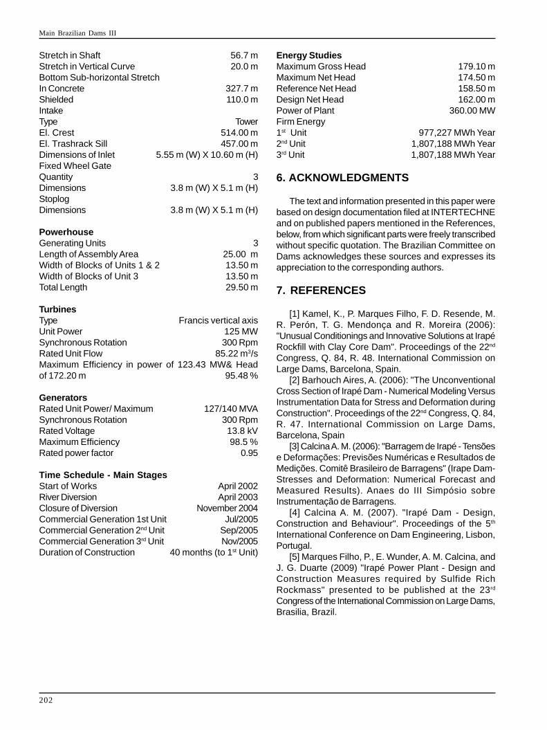
Stretch in Shaft 56.7 mStretch in Vertical Curve 20.0 mBottom Sub-horizontal StretchIn Concrete 327.7 mShielded 110.0 mIntakeType TowerEl. Crest 514.00 mEl. Trashrack Sill 457.00 mDimensions of Inlet 5.55 m (W) X 10.60 m (H)Fixed Wheel GateQuantity 3Dimensions 3.8 m (W) X 5.1 m (H)StoplogDimensions 3.8 m (W) X 5.1 m (H)
PowerhouseGenerating Units 3Length of Assembly Area 25.00 mWidth of Blocks of Units 1 & 2 13.50 mWidth of Blocks of Unit 3 13.50 mTotal Length 29.50 m
TurbinesType Francis vertical axisUnit Power 125 MWSynchronous Rotation 300 RpmRated Unit Flow 85.22 m3/sMaximum Efficiency in power of 123.43 MW& Headof 172.20 m 95.48 %
GeneratorsRated Unit Power/ Maximum 127/140 MVASynchronous Rotation 300 RpmRated Voltage 13.8 kVMaximum Efficiency 98.5 %Rated power factor 0.95
Time Schedule - Main StagesStart of Works April 2002River Diversion April 2003Closure of Diversion November 2004Commercial Generation 1st Unit Jul/2005Commercial Generation 2nd Unit Sep/2005Commercial Generation 3rd Unit Nov/2005Duration of Construction 40 months (to 1st Unit)
Energy StudiesMaximum Gross Head 179.10 mMaximum Net Head 174.50 mReference Net Head 158.50 mDesign Net Head 162.00 mPower of Plant 360.00 MWFirm Energy1st Unit 977,227 MWh Year2nd Unit 1,807,188 MWh Year3rd Unit 1,807,188 MWh Year
6. ACKNOWLEDGMENTS
The text and information presented in this paper werebased on design documentation filed at INTERTECHNEand on published papers mentioned in the References,below, from which significant parts were freely transcribedwithout specific quotation. The Brazilian Committee onDams acknowledges these sources and expresses itsappreciation to the corresponding authors.
7. REFERENCES
[1] Kamel, K., P. Marques Filho, F. D. Resende, M.R. Perón, T. G. Mendonça and R. Moreira (2006):"Unusual Conditionings and Innovative Solutions at IrapéRockfill with Clay Core Dam". Proceedings of the 22nd
Congress, Q. 84, R. 48. International Commission onLarge Dams, Barcelona, Spain.
[2] Barhouch Aires, A. (2006): "The UnconventionalCross Section of Irapé Dam - Numerical Modeling VersusInstrumentation Data for Stress and Deformation duringConstruction". Proceedings of the 22nd Congress, Q. 84,R. 47. International Commission on Large Dams,Barcelona, Spain
[3] Calcina A. M. (2006): "Barragem de Irapé - Tensõese Deformações: Previsões Numéricas e Resultados deMedições. Comitê Brasileiro de Barragens" (Irape Dam-Stresses and Deformation: Numerical Forecast andMeasured Results). Anaes do III Simpósio sobreInstrumentação de Barragens.
[4] Calcina A. M. (2007). "Irapé Dam - Design,Construction and Behaviour". Proceedings of the 5th
International Conference on Dam Engineering, Lisbon,Portugal.
[5] Marques Filho, P., E. Wunder, A. M. Calcina, andJ. G. Duarte (2009) "Irapé Power Plant - Design andConstruction Measures required by Sulfide RichRockmass" presented to be published at the 23rd
Congress of the International Commission on Large Dams,Brasilia, Brazil.


Top Related