


Languages
Pages
Legal


Practice WorkbookThis workbook is designed for use in Live instructor-led training and for OnDemand selfstudy. The explanations and demonstrations are provided by the instructor in the classroom, or in the OnDemand eLectures of this course available on the Bentley LEARN Server (learn.bentley.com).
This practice workbook is formatted for on-screen viewing using a PDF reader. It is also available as a PDF document in the dataset for this course.
DO NOT DISTRIBUTE - Printing for student use is permitted
Templates - Defining End ConditionsThis hands-on training teaches how
This workbook contains exercises to...
Create from scratch a simple multiple slope side slope solution.
Modify a Multi-Slope Cut and Fill Solution to include a Cut Ditch adjacent to the hinge.
Build a Constant Width/Varying Slope Clear Zone
Build a Wall End Condition
Create a Solution that ties into the terrain at the Right of Way Line.
This hands-on training teaches how to create and make major modifications to template side slopes (end conditions). This training focuses on the side slopes connecting the template hinge to the tie down point. You will learn how to create end conditions with multiple cut and fill slope solutions, cut slopes with a ditch adjacent to the hinge, walls, and forced right-of-way solutions.
TRNC01365-1/0002

Copyright © 2014 Bentley Systems, Incorporated 2DO NOT DISTRIBUTE - Printing for student use is permitted
Getting Started
This course is appropriate for any of the Bentley civil software applications powered by OpenRoads Technology including...
Power GEOPAK or GEOPAK
Power InRoads or InRoads
Bentley MX ROAD
PowerCivil for {country}
Dataset Units
Both Imperial and Metric versions of the dataset are available. Throughout this practice workbook Imperial values are specified first and the metric values second. The metric values are enclosed in square brackets. For example: 12’ [3.4m]
Prerequisites
This class assumes that you have a working understanding of templates, including Testing End Conditions. These topics are covered in the Templates - Using and Editing class.

Copyright © 2014 Bentley Systems, Incorporated 3DO NOT DISTRIBUTE - Printing for student use is permitted
Build a Multi-slope End Condition
In this section, we will ….
Launch the software in the Bentley-Civil Workspace and open the class template library.
Build a Multi-slope End Condition targeting the Active Terrain.
1. Launch InRoads, GEOPAK, or MX (or their respective Power versions).
2. Open the Templates.dgn file in the appropriate workspace:
User: examples
Project: Bentley-Civil-Imperial [Bentley-Civil-Metric]
Interface: Bentley-Civil
The Bentley-Civil workspace is delivered with the software as a fully configured environment ready for immediately use in a production environment. All Bentley Civil training uses this workspace. To use this workspace, the User and Project Settings in the MicroStation File Open dialog must be selected as described above.
Note: the datafiles can be installed anywhere. This book assume the files are in C:\Bentley Training\End Conditions\.
3. Open the Create Template dialog by clicking Tasks > Civil Tools > Corridor Modeling > Corridor Creation > Create Template
The Create Template dialog opens the Template Library designated by the CIVIL_ROADWAY_TEMPLATE_LIBRARY environmental variable:
1. In the Create Template dialog File menu, select Open

Copyright © 2014 Bentley Systems, Incorporated 4DO NOT DISTRIBUTE - Printing for student use is permitted
2. Browse to and select the project template library in the class data folder: Defining Side Slopes.itl [Defining Side Slopes - Metric.itl].
Note: Unless the CIVIL_ROADWAY_TEMPLATE_LIBRARY workspace variable is changed, you will have to open the project template library manually every time you open the software.
The templates we create are not just about geometry. Corridor Modeling gives the components and points a longitudinal dimension; they become the permanent model which has a very long shelf life and gets passed to many people. The components and 3D linestrings need to have valid Information Modeling value. In this class we will build Templates with 1) good geometry and 2) good Information Modeling.
Create a Multiple-Slope Solution targeting the Active Terrain
1. Right-click on the template library object, click New > Template.
2. In the new template name, type Cut and Fill.
Create the Cut_1:2 End Condition Component.
1. Right-click in the Current Template window or click the Add menu and select Add New Component > End Condition.
2. In the Current Component frame:
a. Type Cut_1:2 for Name.
b. Set the Feature to Grade_Cut.
c. Set the Priority to 5.
d. Set the Target Type to Terrain Model.
e. Set the Terrain Model to <Active>.
Place the Cut_1:2 Point

Copyright © 2014 Bentley Systems, Incorporated 5DO NOT DISTRIBUTE - Printing for student use is permitted
1. In the Dynamic Settings dialog,
a. Ensure that the Apply Affixes box is clear.
b. Select a Point Name of HINGE.
The Point Style should automatically be set to Grade_Hinge.
c. Select the Precision Input Mode of xy=
d. Type 0,0 and click the Enter key.
The Hinge point is placed and the component is “drawn” to the cursor, awaiting the next point.
2. In the Dynamic Settings dialog,
a. Set the Check for Intersection box.
b. Set the Place Point at Intersection box.
c. Set the End Condition is Infinite box.
d. Clear the Do Not Construct box.
e. Select a Point Name of Cut.
The Point Style should automatically be set to Grade_CutLine.
f. Edit the Point Name to Cut_1:2.
This added information allow hovering over the resulting 3D linestring and seeing the slope.
g. Select the Precision Input Mode of hs=
h. Type 20,50% [5,50%] and click the Enter key.
The Cut_1:2 point is placed and the component is “drawn” to the new cursor position, awaiting the next point.
i. Fit and adjust the Current Template Window if necessary.

Copyright © 2014 Bentley Systems, Incorporated 6DO NOT DISTRIBUTE - Printing for student use is permitted
j. Right-click in the Current Template Window and select Finish.
Test the Template
1. Click the Test button.
2. In the Available Targets list, click <Active>-Terrain Model.
3. Click the Draw button.
4. Move the cursor in the Current Template Window.
5. Verify the template works when in Cut.

Copyright © 2014 Bentley Systems, Incorporated 7DO NOT DISTRIBUTE - Printing for student use is permitted
Create the Cut_1:4 End Condition Component.
1. Right-click in the Current Template window or click the Add menu and select Add New Component > End Condition.
2. In the Current Component frame:
a. Type Cut_1:4 for Name.
b. Set the Feature to Grade_Cut.
c. Set the Priority to 2.
d. Set the Target Type to Terrain Model.
e. Set the Terrain Model to <Active>.
Place the Cut_1:4 Point
1. Click on the Hinge point.
This merges the starting points of the two end condition components, forming an End Condition “tree”. Solutions are sought for each “branch”, starting with the branch with the highest Priority (having the lowest number). The component “rubberbands” indicating it is ready for the next point in the component.
2. In the Dynamic Settings dialog,
a. Set the Check for Intersection box.
b. Set the Place Point at Intersection box.
c. Clear the End Condition is Infinite box.

Copyright © 2014 Bentley Systems, Incorporated 8DO NOT DISTRIBUTE - Printing for student use is permitted
d. Clear the Do Not Construct box.
e. Type a Point Name of Cut_1:4.
f. Set the Point Style to Grade_Cutline.
g. Select the Precision Input Mode of hs=
h. Type 16,25% [4,25%] and click the Enter key.
The Cut_1:4 point is placed and the component is “drawn” to the new cursor position, awaiting the next point.
i. Right-click in the Current Template Window and select Finish.
Test the Template
Copyright © 2014 Bentley Systems, Incorporated 9DO NOT DISTRIBUTE - Printing for student use is permitted
1. Click the Test button.
2. In the Available Targets list, click <Active>-Terrain Model.
3. Click the Draw button.
4. Move the cursor in the Current Template Window.
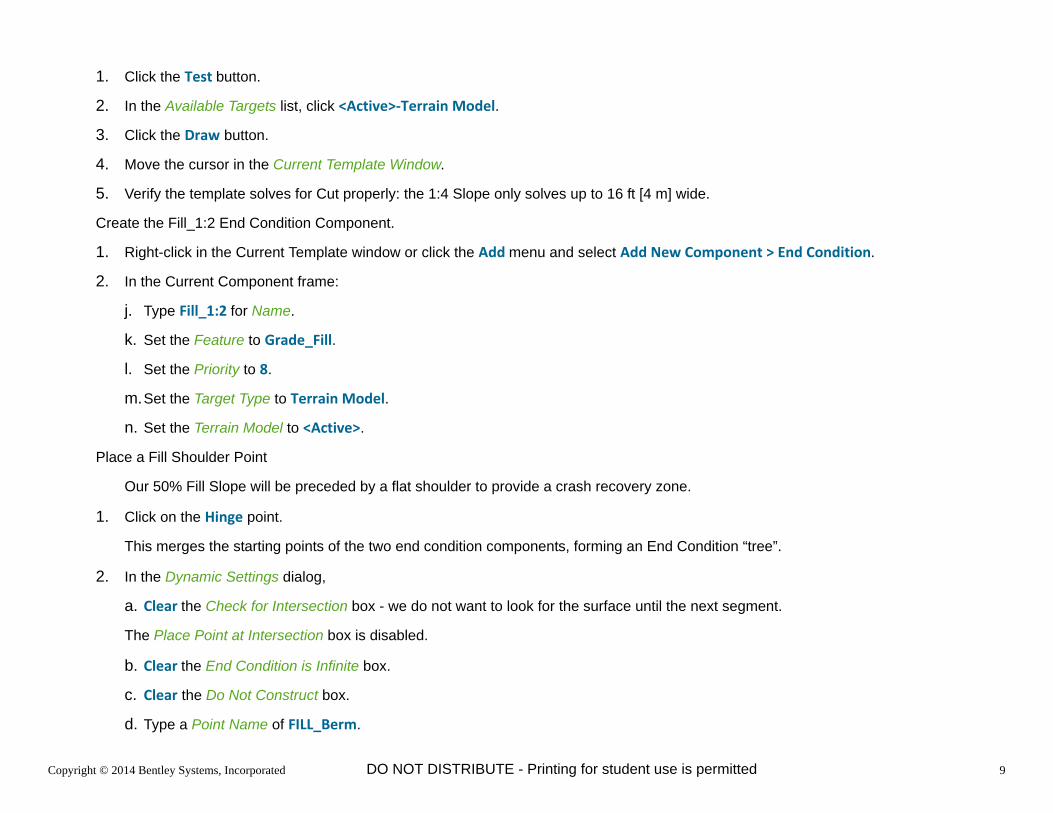
5. Verify the template solves for Cut properly: the 1:4 Slope only solves up to 16 ft [4 m] wide.
Create the Fill_1:2 End Condition Component.
1. Right-click in the Current Template window or click the Add menu and select Add New Component > End Condition.
2. In the Current Component frame:
j. Type Fill_1:2 for Name.
k. Set the Feature to Grade_Fill.
l. Set the Priority to 8.
m.Set the Target Type to Terrain Model.
n. Set the Terrain Model to <Active>.
Place a Fill Shoulder Point
Our 50% Fill Slope will be preceded by a flat shoulder to provide a crash recovery zone.
1. Click on the Hinge point.
This merges the starting points of the two end condition components, forming an End Condition “tree”.
2. In the Dynamic Settings dialog,
a. Clear the Check for Intersection box - we do not want to look for the surface until the next segment.
The Place Point at Intersection box is disabled.
b. Clear the End Condition is Infinite box.
c. Clear the Do Not Construct box.
d. Type a Point Name of FILL_Berm.

Copyright © 2014 Bentley Systems, Incorporated 10DO NOT DISTRIBUTE - Printing for student use is permitted
e. Set the Point Style to Grade_Berm.
f. Select the Precision Input Mode of hs=
g. Type 12,-10% [3,-10%] and click the Enter key.
The Fill_Berm point is placed and the component is “drawn” to the new cursor position, awaiting the next point.
Place the Fill_1:2 Point
3. In the Dynamic Settings dialog,
a. Set the Check for Intersection box.
b. Set the Place Point at Intersection box.
c. Set the End Condition is Infinite box.
d. Clear the Do Not Construct box.
e. Type a Point Name of FILL_1:2.
f. Set the Point Style to Grade_FillLine.
g. Select the Precision Input Mode of hs=
h. Type 10,-50% [3,-50%] and click the Enter key.
Copyright © 2014 Bentley Systems, Incorporated 11DO NOT DISTRIBUTE - Printing for student use is permitted
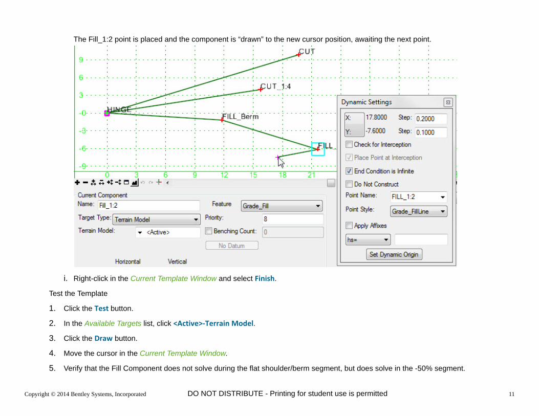
The Fill_1:2 point is placed and the component is “drawn” to the new cursor position, awaiting the next point.
i. Right-click in the Current Template Window and select Finish.
Test the Template
1. Click the Test button.
2. In the Available Targets list, click <Active>-Terrain Model.
3. Click the Draw button.
4. Move the cursor in the Current Template Window.
5. Verify that the Fill Component does not solve during the flat shoulder/berm segment, but does solve in the -50% segment.

Copyright © 2014 Bentley Systems, Incorporated 12DO NOT DISTRIBUTE - Printing for student use is permitted
Create the Fill_1:4 End Condition Component.
1. Right-click in the Current Template window or click the Add menu and select Add New Component > End Condition.
2. In the Current Component frame:
j. Type Fill_1:4 for Name.
k. Set the Feature to Grade_Fill.
l. Set the Priority to 3.
m.Set the Target Type to Terrain Model.
n. Set the Terrain Model to <Active>.
Place the Fill_1:4 Point
1. Click on the Hinge point.
Ensure that the points merge.
2. In the Dynamic Settings dialog,
a. Set the Check for Intersection box.
b. Set the Place Point at Intersection box.
c. Clear the End Condition is Infinite box.
d. Clear the Do Not Construct box.
e. Type a Point Name of Fill_1:4.
f. Set the Point Style to Grade_Fill.
g. Select the Precision Input Mode of hs=
h. Type 16,-25% [4,-25%] and click the Enter key.
The Fill_1:4 point is placed and the component is “drawn” to the new cursor position, awaiting the next point.
i. Right-click in the Current Template Window and select Finish.

Copyright © 2014 Bentley Systems, Incorporated 13DO NOT DISTRIBUTE - Printing for student use is permitted
Test the Template
1. Click the Test button.
2. In the Available Targets list, click <Active>-Terrain Model.
3. Click the Draw button.
4. Move the cursor in the Current Template Window.
5. Verify the template solves for Cut and Fill properly: flatter components before the steeper ones.
6. Save the Template Library.

Copyright © 2014 Bentley Systems, Incorporated 14DO NOT DISTRIBUTE - Printing for student use is permitted
Create a Multi-Slope Cut and Fill Solution with a Cut Ditch adjacent to the Hinge
In this section, we will ….
Create an Cut End Condition that has a Cut Ditch adjacent to the hinge.
Add Parametric Labels so that the Ditch geometry can be changed along Corridors
Copy and Rename an otherwise-suitable End Condition template.
Delete the Incorrect Components, Merge the New Ditch Component and Verify that it works correctly.
1. Right-click on the template library object, click New > Template.
2. In the new template name, type Cut Ditch - Interior.
Create the Cut Ditch End Condition Solution.
1. Right-click in the Current Template window or click the Add menu and select Add New Component > End Condition.
2. In the Current Component frame:
a. Type Cut_1:2 for Name.
b. Set the Feature to Grade_Cut.
c. Set the Priority to 8.
d. Set the Target Type to Terrain Model.
e. Set the Terrain Model to <Active>.
Place the Ditch Portion
Our Ditch will be preceded by a flat shoulder to provide a crash recovery zone.

Copyright © 2014 Bentley Systems, Incorporated 15DO NOT DISTRIBUTE - Printing for student use is permitted
1. In the Dynamic Settings dialog,
a. Ensure that the Apply Affixes box is clear.
b. Select a Point Name of HINGE.
The Point Style should automatically be set to Grade_Hinge.
c. Select the Precision Input Mode of xy=
d. Type 0,0 and click the Enter key.
The Hinge point is placed and the component is “drawn” to the cursor, awaiting the next point.
2. In the Dynamic Settings dialog,
a. Clear the Check for Intersection box - we do not want to look for the surface until after the ditch is drawn.
The Place Point at Intersection box is disabled.
b. Clear the End Condition is Infinite box.
c. Clear the Do Not Construct box.
d. Select a Point Name of DITCH_TOP.
The Point Style should automatically be set to Grade_DitchTop
e. Select the Precision Input Mode of hs=
f. Type 8,-10% [2,-10%] and click the Enter key.
The Ditch Top point is placed and the component is “drawn” to the new cursor position, awaiting the next point.
3. In the Dynamic Settings dialog, the “targeting options” will remain the same:
a. Clear the Check for Intersection box - we do not want to look for the surface until after the ditch is drawn.
The Place Point at Intersection box is disabled.
b. Clear the End Condition is Infinite box.
c. Clear the Do Not Construct box.
d. Select a Point Name of DITCH_FORESLOPE.

Copyright © 2014 Bentley Systems, Incorporated 16DO NOT DISTRIBUTE - Printing for student use is permitted
The Point Style should automatically be set to Grade_Ditch_Foreslope
e. Select the Precision Input Mode of hs=
f. Type 6,-1/3 [2,-1/3] and click the Enter key.
The Ditch Foreslope point is placed and the component is “drawn” to the new cursor position, awaiting the next point.
4. In the Dynamic Settings dialog, the “targeting options” will remain the same:
a. Clear the Check for Intersection box - we do not want to look for the surface until after the ditch is drawn.
The Place Point at Intersection box is disabled.
b. Clear the End Condition is Infinite box.
c. Clear the Do Not Construct box.
d. Select a Point Name of DITCH_BOT.
The Point Style should automatically be set to Grade_DitchBottom.
e. Select the Precision Input Mode of hs=
f. Type 4,0 [1.5,0] and click the Enter key.
The Ditch Bottom point is placed and the component is “drawn” to the new cursor position, awaiting the next point.
5. In the Dynamic Settings dialog, the “targeting options” will remain the same:
a. Clear the Check for Intersection box - we do not want to look for the surface until after the ditch is drawn.
The Place Point at Intersection box is disabled.
b. Clear the End Condition is Infinite box.
c. Clear the Do Not Construct box.
d. Select a Point Name of DITCH_BACKSLOPE.
The Point Style should automatically be set to Grade_Ditch_Foreslope
e. Select the Precision Input Mode of hs=
f. Type 6,1/3 [2,1/3] and click the Enter key.

Copyright © 2014 Bentley Systems, Incorporated 17DO NOT DISTRIBUTE - Printing for student use is permitted
The Ditch Backslope point is placed and the component is “drawn” to the new cursor position, awaiting the next point.
The Ditch Bottom point is placed and the component is “drawn” to the new cursor position, awaiting the next point.
6. In the Dynamic Settings dialog, change the interception settings to an infinite targeting point:
a. Set the Check for Intersection box - we now want to find the terrain.
b. Set the Place Point at Intersection box.
c. Set the End Condition is Infinite box.
d. Clear the Do Not Construct box.
e. Select a Point Name of CUT.
The Point Style should automatically be set to Grade_CutLine
f. Provide a more descriptive Point Name (type Cut_1:2 or Cutline w Ditch (whichever seems more clear to you or your team)).
g. Select the Precision Input Mode of hs=
h. Type 3,50% [3,50%] and click the Enter key.

Copyright © 2014 Bentley Systems, Incorporated 18DO NOT DISTRIBUTE - Printing for student use is permitted
The final daylight point is placed and the component is “drawn” to the new cursor position, awaiting the next point. Note that the drawn length is irrelevant to the engineering since the End Condition is Infinite box is set.
Test the Template
1. Click the Test button.
2. In the Available Targets list, click <Active>-Terrain Model.
3. Click the Draw button.
4. Move the cursor in the Current Template Window.
5. Verify the template solves only during the final 50% Cut segment
Add Parametric Constraints to the Ditch Geometry so that it might be Controlled by Corridors
Ditch geometry varies not only from project to project and from ditch to ditch within a project, but may often vary along the length of the ditch. An oversized ditch takes up a lot of width. Defining Parametric Constraints on the Ditch Points allows shrinking or expanding the ditch to meet minimum hydraulic requirements while taking up the least amount of footprint. Corridors can adjust these Parameters station by station.
1. Double-click the DITCH_FORESLOPE point.
2. In the Point Properties dialog
a. Type Ditch_Foreslope_Slope for the Slope Constraint Value.

Copyright © 2014 Bentley Systems, Incorporated 19DO NOT DISTRIBUTE - Printing for student use is permitted
b. Type Ditch_Foreslope_Width for the Horizontal Constraint Value.
c. Click Apply.
d. Close the dialog.
3. Double-click the DITCH_BOT point.
4. In the Point Properties dialog
a. Type Ditch_Bottom_Slope for the Slope Constraint Value.
b. Type Ditch_Bottom_Width for the Horizontal Constraint Value.
c. Click Apply.
d. Close the dialog.
5. Double-click the DITCH_FORESLOPE point.
6. In the Point Properties dialog
a. Type Ditch_Backslope_Slope for the Slope Constraint Value.
b. Type Ditch_Backslope_Width for the Horizontal Constraint Value.
c. Click Apply.
d. Close the dialog.
We will not do so here, but if you think the interior berm might vary along the corridor, Parametric Labels may be added for the DITCH_TOP point.

Copyright © 2014 Bentley Systems, Incorporated 20DO NOT DISTRIBUTE - Printing for student use is permitted
Copy, Rename and Prepare the “Full” End Treatment
1. Right-click on the Cut and Fill template, click Copy.
2. Right-click on the Cut and Fill template, click Paste.
3. Right-click on the new Cut and Fill1 template, click Rename.
4. Type Fill and Cut with Ditch.
5. Double-click it to make it the Current Template.
6. Delete the 50% Cut component (right-click on it, select Delete Component).
Drag in the Cut Ditch and Test
1. Click on the Cut Ditch Interior template, drag it into the Fill and Cut with Ditch template.
2. Make sure the hinges merge.
3. Test the template.
Copyright © 2014 Bentley Systems, Incorporated 21DO NOT DISTRIBUTE - Printing for student use is permitted
Priority Conflicts
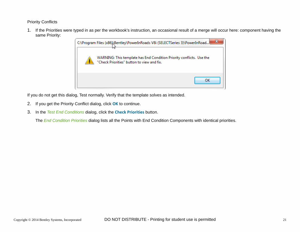
1. If the Priorities were typed in as per the workbook’s instruction, an occasional result of a merge will occur here: component having the same Priority:
If you do not get this dialog, Test normally. Verify that the template solves as intended.
2. If you get the Priority Conflict dialog, click OK to continue.
3. In the Test End Conditions dialog, click the Check Priorities button.
The End Condition Priorities dialog lists all the Points with End Condition Components with identical priorities.

Copyright © 2014 Bentley Systems, Incorporated 22DO NOT DISTRIBUTE - Printing for student use is permitted
4. Click Edit.
The Fix Priorities dialog lists all the components starting from the point and their priorities.
5. Change the Priority of the Cut Ditch Interior to something other than 1, 2 or 8.
6. Click OK to accept the change and close the dialog.
7. Close the End Condition Priorities dialog.

Copyright © 2014 Bentley Systems, Incorporated 23DO NOT DISTRIBUTE - Printing for student use is permitted
8. Test the template.
9. Save the Template Library.

Copyright © 2014 Bentley Systems, Incorporated 24DO NOT DISTRIBUTE - Printing for student use is permitted
Build a Constant Width/Varying Slope Clear Zone
In this section, we will ….
Create an Cut End Condition that has a Cut Ditch adjacent to the hinge
Copy and Rename an otherwise-suitable End Condition template
Delete the Incorrect Components, Merge the New Ditch Component and Verify that it works correctly.
1. Right-click on the template library object, click New > Template.
2. Rename the new template to ClearZone.
3. Double-click the ClearZone template to make it active.
Create the ClearZone_Cut End Condition Component.
1. Right-click in the Current Template window or click the Add menu and select Add New Component > End Condition.
2. In the Current Component frame:
e. Type ClearZone_Cut for Name.
f. Set the Feature to Grade_ClearZone.
g. Set the Priority to 5.
h. Set the Target Type to Terrain Model.
i. Set the Terrain Model to <Active>.
Place the non-seeking Clear Zone width Point
1. In the Dynamic Settings dialog,

Copyright © 2014 Bentley Systems, Incorporated 25DO NOT DISTRIBUTE - Printing for student use is permitted
a. Ensure that the Apply Affixes box is clear.
b. Select a Point Name of HINGE.
The Point Style should automatically be set to Grade_Hinge.
c. Select the Precision Input Mode of xy=
d. Type 0,0 and click the Enter key.
The Hinge point is placed and the component is “drawn” to the cursor, awaiting the next point.
2. In the Dynamic Settings dialog, we want to go horizontally to the full Clear Zone width, without seeking:
a. Clear the Check for Intersection box.
This disables the Place Point at Intersection box.
b. Clear the End Condition is Infinite box.
c. Set the Do Not Construct box.
d. Select a Point Name of DNC.
The Point Style should automatically be set to Draft_DNC (DNC is old term meaning Do Not Construct).
e. Select the Precision Input Mode of hs=
f. Type 18,0 [6,0] and click the Enter key.
The non-constructing point is placed and the component is “drawn” to the new cursor position, awaiting the next point.

Copyright © 2014 Bentley Systems, Incorporated 26DO NOT DISTRIBUTE - Printing for student use is permitted
g. Note that the line segment is not drawn from the Hinge to the DNC. This is due to Do Not Construct setting on the DNC point.
Place the Point that Targets the Ground in Cut
1. In the Dynamic Settings dialog, we want to target the ground, but only in a limited range:
a. Set the Check for Intersection box.
b. Set the Place Point at Intersection box.
c. Clear the End Condition is Infinite box.
d. Clear the Do Not Construct box.
e. Select a Point Name of CLEARZONE_CUT.

Copyright © 2014 Bentley Systems, Incorporated 27DO NOT DISTRIBUTE - Printing for student use is permitted
The Point Style should automatically be set to Grade_CutLine.
f. Select the Precision Input Mode of dl= (delta).
g. Type 0,3 [0,1] and click the Enter key.
h. Right-click in the Current Template Window and select Finish.
The “surface segment” runs directly between the HINGE and the CLEARZONE_CUT point.
i. Test the template.
The template should solve to the Clear width only between “level” and a 1:3 Cut slope.
Create the ClearZone_Fill End Condition Component.

Copyright © 2014 Bentley Systems, Incorporated 28DO NOT DISTRIBUTE - Printing for student use is permitted
This is identical to the ClearZone Cut solution, with the exception of the seek direction.
1. Right-click in the Current Template window or click the Add menu and select Add New Component > End Condition.
2. In the Current Component frame:
j. Type ClearZone_Fill for Name.
k. Set the Feature to Grade_ClearZone.
l. Set the Priority to 6.
m.Set the Target Type to Terrain Model.
n. Set the Terrain Model to <Active>.
Place the non-seeking Clear Zone width Point
1. Place a point at the Hinge point, ensuring a merge.
2. In the Dynamic Settings dialog, we want to go horizontally to the full Clear Zone width, without seeking:
a. Clear the Check for Intersection box.
This disables the Place Point at Intersection box.
b. Clear the End Condition is Infinite box.
c. Set the Do Not Construct box.
d. Select a Point Name of DNC.
The Point Style should automatically be set to Draft_DNC (DNC is old term meaning Do Not Construct).
e. Select the Precision Input Mode of hs=
f. Type 18,0 [6,0] and click the Enter key.
The non-constructing point is placed and the component is “drawn” to the new cursor position, awaiting the next point.

Copyright © 2014 Bentley Systems, Incorporated 29DO NOT DISTRIBUTE - Printing for student use is permitted
g. Note that the line segment is not drawn from the Hinge to the DNC. This is due to Do Not Construct setting on the DNC point.
Place the Point that Targets the Ground in Cut
1. In the Dynamic Settings dialog, we want to target the ground, but only in a limited range:
a. Set the Check for Intersection box.
b. Set the Place Point at Intersection box.
c. Clear the End Condition is Infinite box.
d. Clear the Do Not Construct box.
e. Select a Point Name of CLEARZONE_FILL.
The Point Style should automatically be set to Grade_FillLine.
f. Select the Precision Input Mode of dl= (delta).
g. Type 0,-3 [0,-1] and click the Enter key.
h. Right-click in the Current Template Window and select Finish.

Copyright © 2014 Bentley Systems, Incorporated 30DO NOT DISTRIBUTE - Printing for student use is permitted
The “surface segment” runs directly between the HINGE and the CLEARZONE_FILL point.
i. Test the template.
The template should solve to the Clear width only between a 1:3 Cut slope and a 1:3 Fill slope.

Copyright © 2014 Bentley Systems, Incorporated 31DO NOT DISTRIBUTE - Printing for student use is permitted
Create a Solution that Adds a Cut Wall when it Encounters a 2D Wall Feature
In this section, we will ….
Create a Cut End Condition that draws a Wall when it encounters a 2D Wall Feature
Add a Wall Shape to the Wall Solution
Assemble a Template that solves for Cut with and without a wall feature
Wall, when used along a Corridor, tend to be intermittent features. We will build a cut template that ties into the active terrrain at a (maximum) slope if it does not find a 2D wall feature. If it does, it will draw the (maximum) slope to the horizontal location of the 2D wall feature and then draw a near-vertical wall face segment to the active terrain.
1. Right-click on the template library object, click New > Template.
2. Rename the new template Cut Wall.
Create the End Condition Component that Seeks the Wall Feature.
1. Right-click in the Current Template window or click the Add menu and select Add New Component > End Condition.
2. In the Current Component frame:
a. Type Cut Wall for Name.
b. Set the Feature to Grade_Cut.
c. Set the Priority to 3.
d. Set the Target Type to Feature Definition Horizontal.
e. Set the Feature Definition to Struc_WallPerch.
We have just instructed our component to target the horizontal location of any feature with a Feature Definition of Struc_WallPerch.

Copyright © 2014 Bentley Systems, Incorporated 32DO NOT DISTRIBUTE - Printing for student use is permitted
Place the Hinge and Wall Perch Points
1. In the Dynamic Settings dialog,
a. Ensure that the Apply Affixes box is clear.
b. Select a Point Name of HINGE.
The Point Style should automatically be set to Grade_Hinge.
c. Select the Precision Input Mode of xy=
d. Type 0,0 and click the Enter key.
The Hinge point is placed and the component is “drawn” to the cursor, awaiting the next point.
2. In the Dynamic Settings dialog, we want to infinitely seek and place a point if we find the wall feature:
a. Set the Check for Intersection box.
b. Set the Place Point at Intersection box.
c. Set the End Condition is Infinite box.
d. Clear the Do Not Construct box.
e. Select a Point Name of WALL_PERCH.
f. Set the Point Style to Struc_WallPerch.
g. Select the Precision Input Mode of hs=
h. Type 5,50% [2,50%] and click the Enter key.
i. Right-click to Finish adding to the component.

Copyright © 2014 Bentley Systems, Incorporated 33DO NOT DISTRIBUTE - Printing for student use is permitted
3. Test the component.
a. In the Available Targets list, click Struc_WallHoriz-Feature.
b. Click Draw.
c. Move the cursor and observe that the slope ends at the horizontal location of the feature.

Copyright © 2014 Bentley Systems, Incorporated 34DO NOT DISTRIBUTE - Printing for student use is permitted
Create the End Condition Component that Seeks the Active Terrain.
1. Right-click in the Current Template window or click the Add menu and select Add New Component > End Condition.
2. In the Current Component frame:
a. Type Cut Wall Face for Name.
b. Set the Feature to Structure_Wall
c. Set the Priority to 3.
d. Set the Target Type to Terrain Model.
e. Set the Terrain Model to <Active>.
We have just instructed our component to target the Active Terrain.
3. Place a point at the Hinge point, ensuring a merge.
4. In the Dynamic Settings dialog, we want to infinitely seek and place a point at the active terrain:
a. Set the Check for Intersection box.
b. Set the Place Point at Intersection box.
c. Set the End Condition is Infinite box.
d. Clear the Do Not Construct box.

Copyright © 2014 Bentley Systems, Incorporated 35DO NOT DISTRIBUTE - Printing for student use is permitted
e. Select a Point Name of WALL_TOP.
f. Set the Point Style to Struc_WallTop.
g. Select the Precision Input Mode of dl=
h. Type 0.01,5 [0.01,3] and click the Enter key.
Note that vertical delta of 0.01. Exact Vertical faces cause challenges in terrain triangulation routines and should be avoided.
i. Right-click to Finish adding to the component.
5. Test the template.
6. Save the Template Library.
Add a Wall Shape to the Wall Solution
End Condition Components cannot be closed shapes, but closed shapes must be used for volumes purposes. In this next section we will add a previously-created wall shape to the Wall End Condition.
1. Review the Wall Shape template in the Components folder.
2. Move the WALL_TOP point and observe the results.
3. Double-click the Cut Wall template to make it Current and Editable.
4. Click on the Wall Shape template and drag it into the Cut Wall template.

Copyright © 2014 Bentley Systems, Incorporated 36DO NOT DISTRIBUTE - Printing for student use is permitted
5. Make sure the WALL_PERCH points merge.
Next we need to have the Wall Structure top be controlled by the End Condition point.
6. Right-click the top front point of the wall shape, WALL_TOP1. Click Add Constraint > Vertical.
Note: any point dragged in that has a name duplicated in the Current Template will have a suffix added to maintain unique point names.
7. At the “DB: Select Parent Point, RST: Exit” prompt, click the Wall_Top point.
8. Set the Vertical Offset to 0.
9. Click OK.
10. Test the template.
The wall shape should adjust with wall face component. Note that the shape is always showing when it should be dependent on the end condition success.
We need to make the Wall Shape component a child of the Wall Face End Condition. This way the wall shape will not show unless a cut wall is needed.
1. Double-click on the Struc_Wall component (the wall shape).
2. In the Component Properties dialog,
a. select Cut Wall Face as the Parent Component.
b. Click Apply.
c. Close the dialog.

Copyright © 2014 Bentley Systems, Incorporated 37DO NOT DISTRIBUTE - Printing for student use is permitted
3. Test the template.

Copyright © 2014 Bentley Systems, Incorporated 38DO NOT DISTRIBUTE - Printing for student use is permitted
Create a Solution that ties into the terrain at the Right of Way Line
In this section, we will ….
Create a Cut End Condition that ties into the active Terrain at the Right of Way Line
Create a Cut End Condition component that ties into the active Terrain at 50%
Provide a Cut solution that ties in at 50% or at the Right of Way line if the ROW lines is inside the 1:2 Cut Daylight line.
Sometimes the allowable limits of construction lie within the steepest standard allowable slope. For example, tying in directly to the Right of Way line may be required when the 50% slope solution is exceeded. In this section we will build a template that
solves for a 50% cut slope, unless
the 50% cut slope lies outside the ROW line, then
it will solve directly from the Hinge to the surface at the Right of Way line
The way to solve for this, in End Condition logic, is:
Seek a solution where the ROW feature exists and the surface lies above the 50% cut line
If that fails, solve with a regular 50% cut solution.
1. Right-click on the template library object, click New > Template.
2. Rename the new template Forced ROW.
Create the ROW Solution. First, add the End Condition Component seeking the ROW horizontal location.
1. Right-click in the Current Template window or click the Add menu and select Add New Component > End Condition.

Copyright © 2014 Bentley Systems, Incorporated 39DO NOT DISTRIBUTE - Printing for student use is permitted
2. In the Current Component frame:
a. Type Check_for_ROW for Name.
b. Set the Feature to Grade_Cut.
Note that this Component will not show up in the final model: choose Names and Feature Definitions that “self-document” their purpose.
c. Set the Priority to 2.
d. Set the Target Type to Feature Definition Horizontal.
e. Set the Feature Definition to Geom_ROW.
We have just instructed our component to target the horizontal location of any feature with a Feature Definition of Geom_ROW. If the component fails to find a ROW line, there is no right of way line, the component and the component “branch” fail.
Place the Hinge and ROW_Horiz Points
1. In the Dynamic Settings dialog,
a. Ensure that the Apply Affixes box is clear.
b. Select a Point Name of HINGE.
The Point Style should automatically be set to Grade_Hinge.
c. Select the Precision Input Mode of xy=
d. Type 0,0 and click the Enter key.
The Hinge point is placed and the component is “drawn” to the cursor, awaiting the next point.
2. In the Dynamic Settings dialog, we want to infinitely seek and place a point if we find the wall feature:
a. Set the Check for Intersection box.
b. Set the Place Point at Intersection box.
c. Set the End Condition is Infinite box.
d. Set the Do Not Construct box.
e. Select a Point Name of ROW_at 1:2.

Copyright © 2014 Bentley Systems, Incorporated 40DO NOT DISTRIBUTE - Printing for student use is permitted
f. Set the Point Style to Grade_Cutline.
g. Select the Precision Input Mode of hs=
h. Type 5,50% [2,50%] and click the Enter key.
i. Right-click to Finish adding to the component.
Now add the End Condition Component seeking the Active Terrain above the 50% line at the ROW location. If this component is activated it means that the ROW line was found. If this component fails to find the existing ground, then it means the surface is below the 50% slope threshold.
1. Right-click in the Current Template window or click the Add menu and select Add New Component > End Condition.
2. In the Current Component frame:
a. Type Cut_At_ROW for Name.
b. Set the Feature to Grade_Cut.
c. Set the Priority to 2.
d. Set the Target Type to Terrain Model.
e. Set the Terrain Model to <Active>.
We have just instructed our component to target the active terrain above the 50% slope (= steeper than 50%).
Place the Hinge and Cut_ROW Points
1. In the Dynamic Settings dialog,
a. Ensure that the Apply Affixes box is clear.
b. Place a Point at the ROW_at 1:2 point.
2. In the Dynamic Settings dialog,
a. Set the Check for Intersection box.
b. Set the Place Point at Intersection box.
c. Set the End Condition is Infinite box.
d. Clear the Do Not Construct box.

Copyright © 2014 Bentley Systems, Incorporated 41DO NOT DISTRIBUTE - Printing for student use is permitted
e. Select a Point Name of Cut_ROW.
f. Set the Point Style to Grade_Cutline.
g. Select the Precision Input Mode of dl=
h. Type 0,2 [0,2] and click the Enter key.
i. Right-click to Finish adding to the component.
Add a Component between the Hinge and the CUT_ROW Point.
Because the ROW_HORIZ point is set to Do Not Construct, neither End Condition will display because only one point in each is drawn. We will add a Component between the Hinge and CUT_ROW point.
1. Right-click in the Current Template window or click the Add menu and select Add New Component > Unconstrained.
2. In the Current Component frame:
a. Type Cut_to_ROW for Name.
b. Set the Feature to Grade_Cut.
3. In the Dynamic Settings dialog,
a. Ensure that the Apply Affixes box is clear.
b. Place a Point at the HINGE point.
c. Place a Point at the CUT_ROW point.
d. Right-click to Finish adding to the component.
4. Double-click on the Cut_to_ROW component.
5. For Parent Component, select the Cut_at_ROW component.
We want to make the display of the Grading component conditional on the success of the ROW solutions.
6. Test the template.
Create the Cut_1:2 End Condition Component.
1. Right-click in the Current Template window or click the Add menu and select Add New Component > End Condition.

Copyright © 2014 Bentley Systems, Incorporated 42DO NOT DISTRIBUTE - Printing for student use is permitted
2. In the Current Component frame:
e. Type Cut_1:2 for Name.
f. Set the Feature to Grade_Cut.
g. Set the Priority to 5.
h. Set the Target Type to Terrain Model.
i. Set the Terrain Model to <Active>.
Place the Cut_1:2 Point
3. In the Dynamic Settings dialog,
a. Ensure that the Apply Affixes box is clear.
b. Place a Point at the HINGE point.
The component is “drawn” from the Hinge to the cursor, awaiting the next point.
c. Set the Check for Intersection box.
d. Set the Place Point at Intersection box.
e. Set the End Condition is Infinite box.
f. Clear the Do Not Construct box.
g. Select a Point Name of Cut.
The Point Style should automatically be set to Grade_CutLine.
h. Edit the Point Name to Cut_1:2.
i. Select the Precision Input Mode of hs=
j. Type 8,50% [3,50%] and click the Enter key.
The Cut_1:2 point is placed and the component is “drawn” to the new cursor position, awaiting the next point.
k. Right-click to Finish adding to the component.
4. Test the template. Verify that it solves in all cut situations:

Copyright © 2014 Bentley Systems, Incorporated 43DO NOT DISTRIBUTE - Printing for student use is permitted
Cut - No ROW Feature
Cut at 50% with ROW to the outside of the daylight
Cut at the Surface at the ROW feature, inside the 50% daylight point.
Optional: to make this template more easily used at other “Maximum” Slopes (such as 1:1):
1. Edit the CUT Point and ROW_HORIZ points: Type Max_Slope for the Slope Constraint Label.
2. Verify by changing the value of the Max_Slope Parametric Constraint and Testing the template.
Top Related