


Languages
Pages
Legal

C A S T I R O N F L O O R - S T A N D I N G G A S A T M O S P H E R I C B O I L E R S
DTG 230 S - DTG 330 S
DTG 230 S from 54 to 117 kW, with standard gas burner
DTG 330 S from 119 to 380 kW, with standard gas burner
Heating only(DHW production by independent tank)
Low temperature
DTG 230 S and DTG 330 S are cast iron floor-standing gas atmospheric boilers with 2 stages standard burner. For operation on natural gas with a mains pressure of 20 mbar or 300 mbar; operation possible on propane with conversion kit (option).All models are fitted with a choice of one of the following control panels: DIEMATIC-m3, K3 or B3, see pages 6 to 10.
CONDITIONS OF USE
Max. working pressure: 6 barMax. working temperature: 90°C Adjustable thermostat: - DTG 230… from 30 to 85°C
- DTG 330… from 40 to 85°CSafety thermostat: 110°C
HOMOLOGATION
DTG 230-7 to 230-9 S: B11BSDTG 230-10 to 230-14 S, DTG 330 S: B11
GAS CATEGORY
Natural gases H/E group, or propane with conversion kit (option)
All natural gasesPropane (except DTG 330 S 300 mbar)
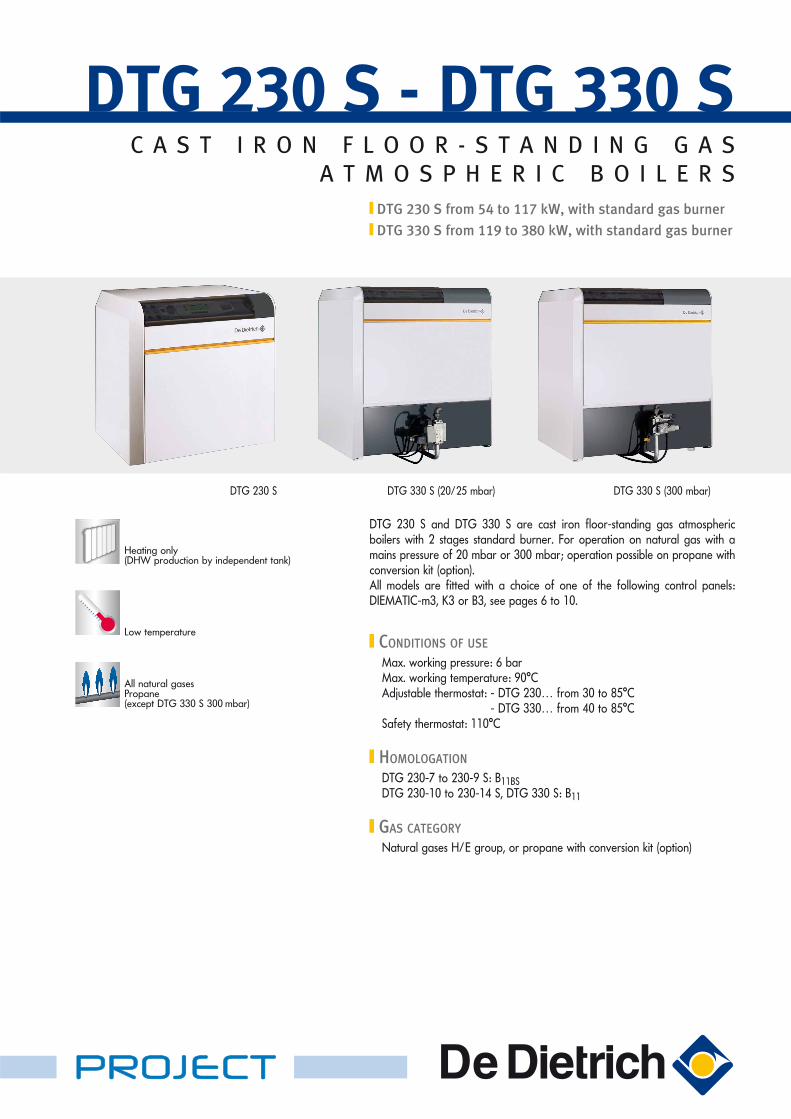
DTG 230 S DTG 330 S (20/25 mbar) DTG 330 S (300 mbar)
PROJECT
2
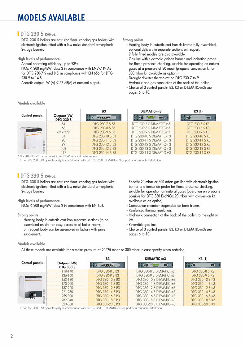
MODELS AVAILABLE
Control panelsB3 DIEMATIC-m3 K3 (1)
Outpout (kW)DTG 230 S
DTG
230_
Q00
01
54 DTG 230-7 S B3 DTG 230-7 S DIEMATIC-m3 DTG 230-7 S K363 DTG 230-8 S B3 DTG 230-8 S DIEMATIC-m3 DTG 230-8 S K3
69.9*/72 DTG 230-9 S B3 DTG 230-9 S DIEMATIC-m3 DTG 230-9 S K381 DTG 230-10 S B3 DTG 230-10 S DIEMATIC-m3 DTG 230-10 S K390 DTG 230-11 S B3 DTG 230-11 S DIEMATIC-m3 DTG 230-11 S K399 DTG 230-12 S B3 DTG 230-12 S DIEMATIC-m3 DTG 230-12 S K3108 DTG 230-13 S B3 DTG 230-13 S DIEMATIC-m3 DTG 230-13 S K3117 DTG 230-14 S B3 DTG 230-14 S DIEMATIC-m3 DTG 230-14 S K3
* The DTG 230-9… can be set to 69.9 kW for small boiler rooms.(1) The DTG 230…K3 operates only in combination with a DTG…230 DIEMATIC-m3 as part of a cascade installation.
Control panelsB3 DIEMATIC-m3 K3 (1)
Outpout (kW)DTG 330 S
DTG
330_
Q00
01
119-140 DTG 330-8 S B3 DTG 330-8 S DIEMATIC-m3 DTG 330-8 S K3136-160 DTG 330-9 S B3 DTG 330-9 S DIEMATIC-m3 DTG 330-9 S K3153-180 DTG 330-10 S B3 DTG 330-10 S DIEMATIC-m3 DTG 330-10 S K3170-200 DTG 330-11 S B3 DTG 330-11 S DIEMATIC-m3 DTG 330-11 S K3187-220 DTG 330-12 S B3 DTG 330-12 S DIEMATIC-m3 DTG 330-12 S K3221-260 DTG 330-14 S B3 DTG 330-14 S DIEMATIC-m3 DTG 330-14 S K3255-300 DTG 330-16 S B3 DTG 330-16 S DIEMATIC-m3 DTG 330-16 S K3289-340 DTG 330-18 S B3 DTG 330-18 S DIEMATIC-m3 DTG 330-18 S K3323-380 DTG 330-20 S B3 DTG 330-20 S DIEMATIC-m3 DTG 330-20 S K3
(1) The DTG 330…K3 operates only in combination with a DTG 330… DIEMATIC-m3 as part of a cascade installation
DTG 230 S boilers are cast iron floor-standing gas boilers with electronic ignition, fitted with a low noise standard atmospheric 2-stage burner.
High levels of performanceAnnual operating efficiency up to 93%NOx < 200 mg/kW, class 2 in compliance with EN297 Pr A2 for DTG 230-7 S and 8 S, in compliance with EN 656 for DTG 230-9 to 14 S.Acoustic output LW (A) < 57 dB(A) at nominal output.
Strong points- Heating body in eutectic cast iron delivered fully assembled,
optional delivery in separate sections on request. 2 fully fitted models are also available.
- Gas line with electronic ignition burner and ionisation probe for flame presence checking, suitable for operating on natural gases at a pressure of 20 mbar (propane conversion kit or 300 mbar kit available as options).
- Draught diverter thermostat on DTG 230-7 to 9…- Hydraulic and gas connection at the back of the boiler.- Choice of 3 control panels: B3, K3 or DIEMATIC-m3: see
pages 6 to 10.
DTG 230 S RANGE
DTG 330 S boilers are cast iron floor-standing gas boilers with electronic ignition, fitted with a low noise standard atmospheric 2-stage burner.
High levels of performanceNOx < 200 mg/kW, class 2 in compliance with EN 656.
Strong points- Heating body in eutectic cast iron separate sections (to be
assembled on site for easy access to all boiler rooms): on request body can be assembled in factory with price supplement.
- Specific 20 mbar or 300 mbar gas line with electronic ignition burner and ionisation probe for flame presence checking, suitable for operation on natural gases (operation on propane possible for DTG 330 EcoNOx 20 mbar with conversion kit available as an option).
- Combustion chamber suspended on base frame.- Reinforced thermal insulation.- Hydraulic connection at the back of the boiler, to the right or
left- Reversible gas line.- Choice of 3 control panels: B3, K3 or DIEMATIC-m3: see
pages 6 to 10.
DTG 330 S RANGE
Models available
Models availableAll these models are available for a mains pressure of 20/25 mbar or 300 mbar: please specify when ordering.

3
TECHNICAL SPECIFICATIONS
DESCRIPTION
Boiler shown:DTG 230 S DIEMATIC-m3
DTG 230 S
Gas line DTG 230 S
DTG 330 S
Boiler shown:DTG 330 S DIEMATIC-m3 20/25 mbar
Gas line DTG 330 S-300 mbar
Flue gas nozzle
Draught diverter hood with inspection hatch and motorised flue damper
Draught diverter thermostat:- standard on 7, 8 and
9 sect. models- optional on other
models
Heating flow
Flue damper motor
Insulation for heating body, combustion chamber and draught diverter in glass wool, thickness 100 mm + fibreglass coat
Heating return with drainage
Floor plate
Top insulation, draught diverter
Electrical connection zone
DIEMATIC-m3, B3 or K3 control panel (spec. see
p. 6 to 10)
Eutectic cast iron heating body
Gas inlet
Combustionchamber irrigated
on 3 sides
Casing in enamelled white sheet steel
1st stage gas valve with safety control box
Pressure outlet
2nd stage gas valve2-stage total premix atmospheric burner(removable drawer)
Ignition burner with ignition electrode and ionisation probe
Removable section for eventual assembly of the
safety valve + gas pressure switch kit (GC191) available
as options
Flue gas nozzle
Draught diverterhood withinspection hatch
Heating flow
Insulation for heating body, combustion chamber and draught diverter in glass wool, thickness 100 mm + fibreglass coatHeating returnwith drainage
Rear insulation
Burner drawer guidance system on rollers
Removable burner drawer
Top insulation, draught diverter
Electrical connection zone
DIEMATIC-m 3, B3 or K3 control panel (spec.
see p. 6 to 10)
Casing inenamelled white
sheet steel
Eutectic cast iron heating body
Gas inlet(reversible)
Ignition transformer
Ignition electrode
Ignition burner
Ionisation probe
2-stage valve-regulator unit with
min. pressure switch
2-stage total premix burnerBurner drawer guidance
system on rollers
Standard 2-stageatmospheric burner
Ignition transformer
Ignition electrode
Ignition burner
Ionisation probe
2-stage valve-regulator unit with min. pressure switch and max. pressure switch
8502
F009
DTG
230_
F000
385
38Q
010
DTG
330_
F000
3
4
TECHNICAL SPECIFICATIONS
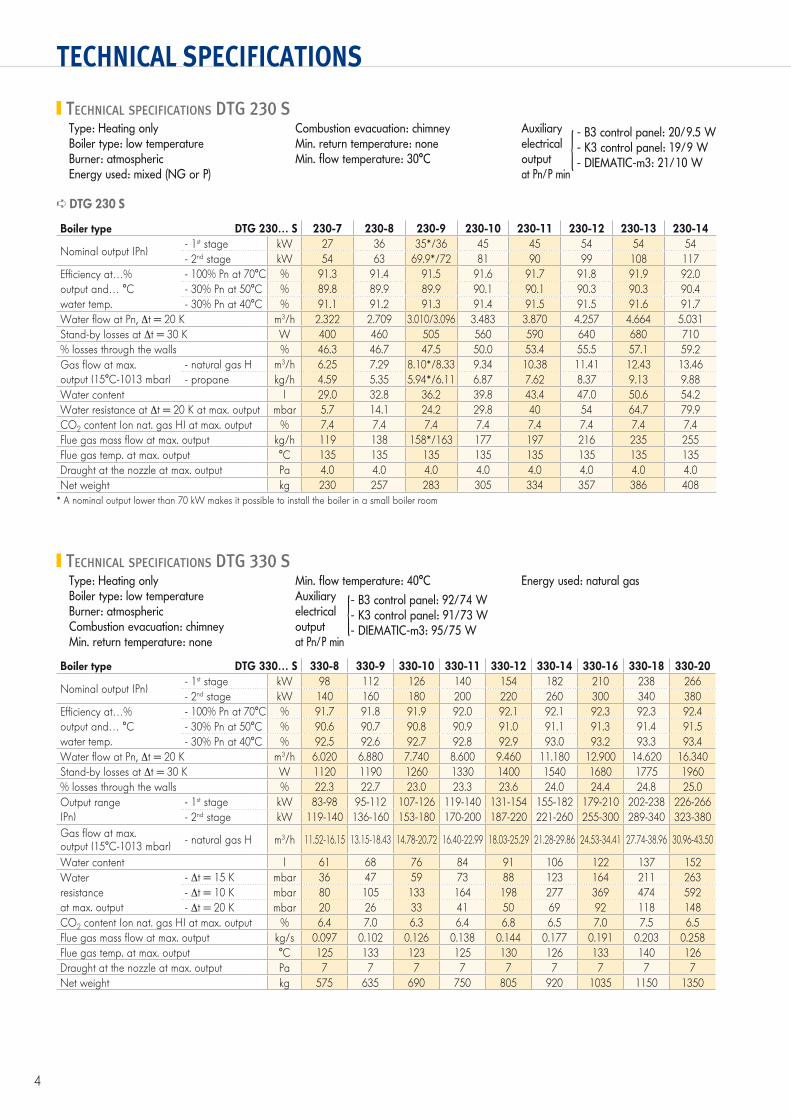
Boiler type DTG 330… S 330-8 330-9 330-10 330-11 330-12 330-14 330-16 330-18 330-20
Nominal output (Pn)- 1st stage kW 98 112 126 140 154 182 210 238 266- 2nd stage kW 140 160 180 200 220 260 300 340 380
Efficiency at…% - 100% Pn at 70°C % 91.7 91.8 91.9 92.0 92.1 92.1 92.3 92.3 92.4output and… °C - 30% Pn at 50°C % 90.6 90.7 90.8 90.9 91.0 91.1 91.3 91.4 91.5water temp. - 30% Pn at 40°C % 92.5 92.6 92.7 92.8 92.9 93.0 93.2 93.3 93.4Water flow at Pn, t = 20 K m3/h 6.020 6.880 7.740 8.600 9.460 11.180 12.900 14.620 16.340Stand-by losses at t = 30 K W 1120 1190 1260 1330 1400 1540 1680 1775 1960% losses through the walls % 22.3 22.7 23.0 23.3 23.6 24.0 24.4 24.8 25.0Output range - 1st stage kW 83-98 95-112 107-126 119-140 131-154 155-182 179-210 202-238 226-266(Pn) - 2nd stage kW 119-140 136-160 153-180 170-200 187-220 221-260 255-300 289-340 323-380Gas flow at max. output (15°C-1013 mbar) - natural gas H m3/h 11.52-16.15 13.15-18.43 14.78-20.72 16.40-22.99 18.03-25.29 21.28-29.86 24.53-34.41 27.74-38.96 30.96-43.50
Water content l 61 68 76 84 91 106 122 137 152Water - t = 15 K mbar 36 47 59 73 88 123 164 211 263resistance - t = 10 K mbar 80 105 133 164 198 277 369 474 592at max. output - t = 20 K mbar 20 26 33 41 50 69 92 118 148CO2 content (on nat. gas H) at max. output % 6.4 7.0 6.3 6.4 6.8 6.5 7.0 7.5 6.5Flue gas mass flow at max. output kg/s 0.097 0.102 0.126 0.138 0.144 0.177 0.191 0.203 0.258Flue gas temp. at max. output °C 125 133 123 125 130 126 133 140 126Draught at the nozzle at max. output Pa 7 7 7 7 7 7 7 7 7Net weight kg 575 635 690 750 805 920 1035 1150 1350
Boiler type DTG 230… S 230-7 230-8 230-9 230-10 230-11 230-12 230-13 230-14
Nominal output (Pn)- 1st stage kW 27 36 35*/36 45 45 54 54 54- 2nd stage kW 54 63 69.9*/72 81 90 99 108 117
Efficiency at…% - 100% Pn at 70°C % 91.3 91.4 91.5 91.6 91.7 91.8 91.9 92.0output and… °C - 30% Pn at 50°C % 89.8 89.9 89.9 90.1 90.1 90.3 90.3 90.4water temp. - 30% Pn at 40°C % 91.1 91.2 91.3 91.4 91.5 91.5 91.6 91.7Water flow at Pn, t = 20 K m3/h 2.322 2.709 3.010/3.096 3.483 3.870 4.257 4.664 5.031Stand-by losses at t = 30 K W 400 460 505 560 590 640 680 710% losses through the walls % 46.3 46.7 47.5 50.0 53.4 55.5 57.1 59.2Gas flow at max. - natural gas H m3/h 6.25 7.29 8.10*/8.33 9.34 10.38 11.41 12.43 13.46output (15°C-1013 mbar) - propane kg/h 4.59 5.35 5.94*/6.11 6.87 7.62 8.37 9.13 9.88Water content l 29.0 32.8 36.2 39.8 43.4 47.0 50.6 54.2Water resistance at t = 20 K at max. output mbar 5.7 14.1 24.2 29.8 40 54 64.7 79.9CO2 content (on nat. gas H) at max. output % 7.4 7.4 7.4 7.4 7.4 7.4 7.4 7.4Flue gas mass flow at max. output kg/h 119 138 158*/163 177 197 216 235 255Flue gas temp. at max. output °C 135 135 135 135 135 135 135 135Draught at the nozzle at max. output Pa 4.0 4.0 4.0 4.0 4.0 4.0 4.0 4.0Net weight kg 230 257 283 305 334 357 386 408
* A nominal output lower than 70 kW makes it possible to install the boiler in a small boiler room
DTG 230 S
TECHNICAL SPECIFICATIONS DTG 230 SType: Heating onlyBoiler type: low temperatureBurner: atmosphericEnergy used: mixed (NG or P)
Combustion evacuation: chimneyMin. return temperature: noneMin. flow temperature: 30°C
Auxiliary - B3 control panel: 20/9.5 Welectrical - K3 control panel: 19/9 Woutput - DIEMATIC-m3: 21/10 Wat Pn/P min
TECHNICAL SPECIFICATIONS DTG 330 SType: Heating onlyBoiler type: low temperatureBurner: atmosphericCombustion evacuation: chimneyMin. return temperature: none
Min. flow temperature: 40°C Auxiliary - B3 control panel: 92/74 Welectrical - K3 control panel: 91/73 Woutput - DIEMATIC-m3: 95/75 Wat Pn/P min
Energy used: natural gas

5
TECHNICAL SPECIFICATIONS
MAIN DIMENSIONS (MM AND INCHES) DTG 230 S
DTG 330 S3
73
E 79
ø G
B
19
2
82
5
93
0
C F
A
37
2
3
4
1
2
5
� Heating flow R 1" 1/2 (1)� Heating return R 1" 1/2 (1)� Safety valve connection Rp 1"� Drainage Rp 3/4"� Gas inlet R 1"
(1) Welded connection possibleR: ThreadingRp: Tapped connection D
TG23
0_F0
001
1406
B
H
= =
ø C
D
64
GJ
410
375130
A
1006
130
E
60
ø F(1)(2)
(1)
1
2
3
4� Heating flow R 2" (1)� Heating return R 2"� Drainage and filling hole Rp 3/4"� Flue gas nozzle Ø C
(1) The hydraulic connections must be made at the same side (either right or left) but never in quincunx. Welded connection possible.
(2) The gas connection can be made on the right or left of the boiler.
R: ThreadingRp: Tapped connection D
TG33
0_F0
001A
DTG 230-7 230-8 230-9 230-10 230-11 230-12 230-13 230-14A 863 946 1113 1113 1280 1280 1447 1447B 952 952 1007 1007 1007 1007 1007 1007C 102 102 124 124 124 124 124 124E 75 75 159 75 159 75 159 75F 452 494 536 578 619 661 703 703Ø G 180 180 180 200 200 200 220 220
DTG 330-8 330-9 330-10 330-11 330-12 330-14 330-16 330-18 330-20A 1362 1362 1362 1362 1362 1412 1412 1412 1462B 970 1058 1146 1234 1322 1498 1674 1850 2026Ø C 250 250 300 300 300 350 350 350 400D 632 720 808 896 984 1160 1336 1512 1688E 165 165 165 165 165 190 190 190 220Ø F 20/25 mbar (2) Rp1" Rp1" Rp1" Rp1" Rp1" Rp 1" 1/4 Rp 1" 1/4 Rp 1" 1/4 Rp 1" 1/2Ø F 300 mbar (2) Rp 3/4 Rp 3/4" Rp 3/4" Rp 3/4" Rp 3/4" Rp 3/4" Rp 3/4" Rp 3/4" Rp 3/4"G 447 491 535 579 623 704 792 880 963H 445 445 445 445 445 454 454 454 507J 1094 1094 1094 1094 1094 1194 1194 1194 1194

6
CHOICE OF CONTROL PANEL
2 types of control panel are possible:
The control panel is chosen according to the installation to be constructed:
INSTALLATION WITH A SINGLE BOILER
2 types of control panel are required: 1 DIEMATIC-m3 control panel for the first boiler in the cascade (master boiler) and 1 K3 control panel for each of the slave boilers:
CASCADE INSTALLATION OF 2 TO 10 BOILERS
B3 and DIEMATIC-m3 control panels include the “DHW priority” function and can therefore be completed with 1 DHW sensor- package AD212 – for controlling an independent tank.
DHW PRODUCTION
TS
N L
TS
N L
TS
N L
TS
N L
TS
N L
TS
N L
DIEMATIC-m3DTG 230...DTG 330...
MMMM
M M
A single circuit with mixing valve
2 circuits, one of which with mixing valve
2 circuits, each with a mixing valve
MMM
3 circuits, 2 of which with mixing valve
3 circuits, each with a mixing valve
1 PCB FM 48 2 PCBs FM 48
1 flow sensor AD 199
1 flow sensor AD 199
1 flow sensor AD 199
+
1 PCB FM 48
+
2 PCBs FM 48
B3
for controlling a single direct circuit
for controlling a direct circuit (without mixing valve)
or depending on the optional equipment connected, for:
option:
option:
(master)
option:
MMMM
M M
A single circuit with mixing valve
2 circuits, one of which with mixing valve
2 circuits, each with a mixing valve
MMM
MMM
3 circuits, 2 of which with mixing valve
3 circuits, each with a mixing valve
3 circuits with mixing valve
MM
2 circuits with mixing valve
M
1 circuit with mixing valve
TS
N L
TS
N L
TS
N L
TS
N L
TS
N L
TS
N L
1 PCB FM 48 2 PCBs FM 48
1 flow sensor AD 199
1 flow sensor AD 199
1 flow sensor AD 199
+
+ +
1 PCB FM 48
+
2 PCBs FM 48
TS
N L
TS
N L
TS
N L
TS
N L
TS
N L
TS
N L
1 Package AD 220 1 Package AD 220 1 Package AD 220
2 PCBs FM 48
1 PCB FM 48
Boiler 1
Boiler 2
for controlling a direct circuit (without mixing valve)
or depending on the optional equipment connected, for:
in addition, for each of the slave boilers, depending on the optional equipment connected, for:
up to 10 boilers: for each additional slave boiler connected, it is possible to control up to 3 additional valve circuits
BUS
BUS
K3
DIEMATIC-m3
K3
DTG
230_
F000
5
7
CONTROL PANELS
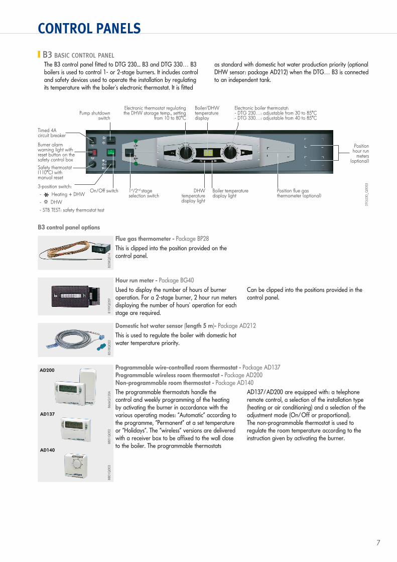
B3 BASIC CONTROL PANELThe B3 control panel fitted to DTG 230... B3 and DTG 330… B3 boilers is used to control 1- or 2-stage burners. It includes control and safety devices used to operate the installation by regulating its temperature with the boiler’s electronic thermostat. It is fitted
as standard with domestic hot water production priority (optional DHW sensor: package AD212) when the DTG… B3 is connected to an independent tank.
Timed 4Acircuit breaker
Pump shutdownswitch
Electronic thermostat regulating the DHW storage temp., setting
from 10 to 80°C
Boiler/DHW temperature display
Electronic boiler thermostat:- DTG 230…: adjustable from 30 to 85°C- DTG 330…: adjustable from 40 to 85°C
Positionhour run
meters(optional)
Position flue gas thermometer (optional)
Burner alarm warning light with reset button on the safety control box
1st/2nd stage selection switch
DHW temperature display light
Boiler temperature display light
Safety thermostat(110°C) withmanual reset
3-position switch:- Heating + DHW- DHW- STB TEST: safety thermostat test
DTG
230_
Q00
03
8358
Q01
4
Flue gas thermometer - Package BP28This is clipped into the position provided on the control panel.
8199
Q05
9
Hour run meter - Package BG40Used to display the number of hours of burner operation. For a 2-stage burner, 2 hour run meters displaying the number of hours’ operation for each stage are required.
Can be clipped into the positions provided in the control panel.
8518
Q02
2
Domestic hot water sensor (length 5 m)- Package AD212This is used to regulate the boiler with domestic hot water temperature priority.
8666
Q12
0A
AD200 Programmable wire-controlled room thermostat - Package AD137Programmable wireless room thermostat - Package AD200Non-programmable room thermostat - Package AD140 The programmable thermostats handle the control and weekly programming of the heating by activating the burner in accordance with the various operating modes: “Automatic” according to the programme, “Permanent” at a set temperature or “Holidays”. The “wireless” versions are delivered with a receiver box to be affixed to the wall close to the boiler. The programmable thermostats
AD137/AD200 are equipped with: a telephone remote control, a selection of the installation type (heating or air conditioning) and a selection of the adjustment mode (On/Off or proportional). The non-programmable thermostat is used to regulate the room temperature according to the instruction given by activating the burner.
B3 control panel options
On/Off switch
AD137
AD140
8801
Q00
288
01Q
003

8
CONTROL PANELS
DIEMATIC-M3 AND K3 CONTROL PANELS
DIEMATIC-m3 control panel
The DIEMATIC-m3 control panel is a very advanced control panel, which includes electronic programmable regulation as standard to modulate the boiler temperature by activating the 2-stage burner according to the outside temperature and, in certain cases, the room temperature, if a CDI D. iSystem or CDR D. iSystem interactive remote control is connected (optional).As standard, DIEMATIC-m3 is capable of automatically operating a central heating installation with a direct circuit without mixing valve or a circuit with mixing valve (the flow sensor – package AD199 – must be ordered separately, however).By connecting another 1 or 2 “PCB + sensor for 1 valve circuit” options (package FM48), it is therefore possible to control up to 3 circuits with mixing valve and each of these circuits can be fitted with a CDI D. iSystem or CDR D. iSystem remote control (optional).Connection of a domestic hot water sensor enables the programming and regulation of a DHW circuit by activating
a control system on the load pump; DHW looping can be handled thanks to the auxiliary contact which includes its own programming.DIEMATIC-m3 also provides antifreeze protection for the installation and the living space if the home is unoccupied and can be programmed 1 year in advance for a period of up to 99 days.Furthermore, the control system includes an “anti-legionella” protection option.Moreover, in the context of larger installations, it is possible to connect from 2 to 10 boilers in cascade: only the first of these boilers will be fitted with the DIEMATIC-m3 control panel, whilst the others will be fitted with the K3 control panel. Each of these DTG… K3 boilers can in turn be complemented with PCBs (AD220 + 1 or 2 x FM48) for controlling up to 3 circuits with mixing valve (see p. 7) with or without CDI D. iSystem or CDR D. iSystem remote control.
The control module integrated into the DIEMATIC-m3 control panel enables the installer to set the parameters for the entire heating installation, whatever its degree of complexity. It can be used to manage equally well:- a DTG… DIEMATIC-m3 boiler installed alone.- or a cascade of boilers in which only the first will be fitted with
the DIEMATIC-m3 control panel, all the others being fitted with the K3 control panel.
It also enables the user to programme each of the circuits in the installation independently, including those connected to the slave boilers with K3 control panel in a cascade installation. It makes it possible to select the appropriate operating mode for heating (Auto mode depending on programming, “Day”, “Night” or “Antifreeze” temperature mode, whether temporary or permanent), and for domestic hot water production (Auto, temporary or permanent forced load). It also makes it possible to access the various settings parameters and measurements in the installation to modify them or simply consult them, etc.
DIEMATIC-m3 control module
0
SUNDAY
0
SUNDAY
Control module, flap closed
Control module, flap open
GT3
30_F
0017
Timed 4Acircuit breaker
Pump shutdown switch
DIEMATIC-m3 control module
Boiler thermometer
On/Offswitch
1st/2nd stage selection switch
Boiler heating curve
Safety thermostat(110°C) withmanual reset3-position switch:- auto- manual- safety thermostat test
Boiler thermostat:- DTG 230…: adjustable from 30 to 85°C- DTG 330…: adjustable from 40 to 85°C
DTG
230_
Q00
04
Burner alarmwarning light with reset button on the safety control box
USB connector

9
CONTROL PANELS
K3 control panel
Timed 4Acircuit breaker
Pump shutdownswitch
1st/2nd stage selectionswitch
Boiler thermometer
Burner alarm light
On/Offswitch
Boiler thermostat:- DTG 230…: adjustable from 30 to 85°C- DTG 330…: adjustable from 40 to 85°C
Safety thermostat(110°C) withmanual reset
3-position switch:- auto- manual- safety thermostat test
DTG
230_
Q00
2
NB: All of the settings and measurement parameters on each of the boilers in cascades fitted with the K3 control panel can be accessed on the DIEMATIC-m3 control panel on the master boiler.
DIEMATIC-m3 and K3 control panel options
GT2
20_Q
0001
Flow sensor downstream of the valve (length 2.5 m)- Package AD199This sensor is required in installations which have only circuits with mixing valve (no direct
circuit) to connect the first of these circuits to the DIEMATIC-m3 control panel – see page 7.
8575
Q03
6
PCB + sensor for 1 mixing valve - Package FM48This is used to control a mixing valve with a 2-direction electrothermal or electromechanical motor. The valve circuit and its circulating pump can be programmed independently.
Note:- In addition to sensor AD199 for the first valve
circuit, DIEMATIC-m3 can be fitted with 1 or 2 additional “PCB + sensor for 1 mixing valve” options – see p. 7.
- K3 can also be fitted with these PCBs in addition to the AD220 PCB required for the first valve circuit connected to a DTG… K3.
8518
Q02
2
Domestic hot water sensor (length 5 m)- Package AD212This is used for priority temperature regulation and programming domestic hot water production
It handles the boiler sensor function for DTG… K3 in a modulating cascade installation.
8575
Q04
8
Flue gas sensor (length 5 m)- Package FM47This can be fitted to a DTG… DIEMATIC-m3 boiler or, in cascade installations, to each of the DTG… DIEMATIC-m3 or DTG… K3 boilers in this cascade.
It enables the user to read the flue gas temperature and thus check the cleanliness of the heat exchange surfaces in the boiler body.
GT3
30_F
0004
Relay PCB + sensors for the first valve circuit on a DTG… K3 - Package AD220This PCB is required to connect the first valve circuit with mixing valve to a DTG… boiler with K3 control panel as part of a cascade installation.
NB: 1 “relay PCB + sensors for first valve circuit” per DTG… K3 boiler can be connected.
Connector for programming
unit
10
CONTROL PANELS
8575
Q03
7
Simplified remote control with room sensor - Package FM52The connection of a simplified remote control is used to override certain instructions from the DIEMATIC m-3 or K3 control panel from the room in which it is installed: programme override (permanent comfort or low) and set room
temperature override (±3.5°C). It is also used to enable the self-adaptability of the heating curve for the circuit concerned (1 simplified remote control per circuit).
DIEMATIC-m3 and K3 control panel options
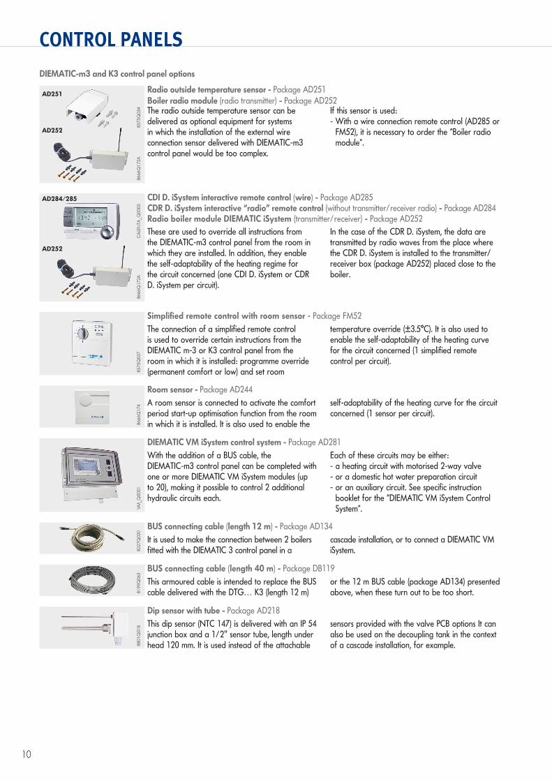
Radio outside temperature sensor - Package AD251Boiler radio module (radio transmitter) - Package AD252The radio outside temperature sensor can be delivered as optional equipment for systems in which the installation of the external wire connection sensor delivered with DIEMATIC-m3 control panel would be too complex.
If this sensor is used:- With a wire connection remote control (AD285 or
FM52), it is necessary to order the “Boiler radio module”.
8666
Q17
2A85
75Q
034
AD252
CDI D. iSystem interactive remote control (wire) - Package AD285CDR D. iSystem interactive “radio” remote control (without transmitter/receiver radio) - Package AD284Radio boiler module DIEMATIC iSystem (transmitter/receiver) - Package AD252These are used to override all instructions from the DIEMATIC-m3 control panel from the room in which they are installed. In addition, they enable the self-adaptability of the heating regime for the circuit concerned (one CDI D. iSystem or CDR D. iSystem per circuit).
In the case of the CDR D. iSystem, the data are transmitted by radio waves from the place where the CDR D. iSystem is installed to the transmitter/receiver box (package AD252) placed close to the boiler.
8666
Q17
2AC
ALE
NTA
_Q00
05
AD284/285
AD252
Dip sensor with tube - Package AD218This dip sensor (NTC 147) is delivered with an IP 54 junction box and a 1/2" sensor tube, length under head 120 mm. It is used instead of the attachable
sensors provided with the valve PCB options It can also be used on the decoupling tank in the context of a cascade installation, for example.88
01Q
018
BUS connecting cable (length 12 m) - Package AD134It is used to make the connection between 2 boilers fitted with the DIEMATIC 3 control panel in a
cascade installation, or to connect a DIEMATIC VM iSystem.82
27Q
020
BUS connecting cable (length 40 m) - Package DB119This armoured cable is intended to replace the BUS cable delivered with the DTG… K3 (length 12 m)
or the 12 m BUS cable (package AD134) presented above, when these turn out to be too short.81
99Q
063
Room sensor - Package AD244A room sensor is connected to activate the comfort period start-up optimisation function from the room in which it is installed. It is also used to enable the
self-adaptability of the heating curve for the circuit concerned (1 sensor per circuit).
8666
Q17
4
DIEMATIC VM iSystem control system - Package AD281With the addition of a BUS cable, the DIEMATIC-m3 control panel can be completed with one or more DIEMATIC VM iSystem modules (up to 20), making it possible to control 2 additional hydraulic circuits each.
Each of these circuits may be either: - a heating circuit with motorised 2-way valve- or a domestic hot water preparation circuit- or an auxiliary circuit. See specific instruction
booklet for the “DIEMATIC VM iSystem Control System”.VM
_Q00
01
AD251
11
BOILER OPTIONS
8502
Q01
1
Kit for operating at 300 mbar – Package GC192The 300 mbar kit includes a valve unit with 2 min. and max. gas pressure switches. It is fitted to the gas supply to the boiler and is used to connect it to a gas pressure of 300 mbar.
Note: The parallel assembly of this kit and the safety + gas pressure switch kit (Package GC191) is not possible.
DTG 230 S OPTIONS
8502
Q01
2
Safety valve + gas pressure switch kit – Package GC191This class A valve is fitted to the gas line upstream of the solenoid valves if an additional safety measure is required.
Note: The parallel assembly of a kit for operating at 300 mbar (Package GC192) and this safety valve + pressure switch kit is not possible.
8502
Q00
9
100 VA insulation transformer – Package GC123This transformer is required to guarantee correct flame detection by ionisation if the electrical
network does not include neutral or if neutral is not connected to the earth.
8502
Q01
3
Draught diverter thermostat – Package GC22 (for models DTG 230-10 to 230-14)This thermostat shuts down the gas supply to the boiler in the event of combustion gas overflow caused by poor draught in the chimney.
Propane conversion kit – Package GC193This kit is used to convert the DTG 230 S for operation on propane
NB: The DTG 230… is delivered preset to operate on natural gas H. Conversion kits for natural gas L are included with the boiler as standard
Retour chauffage
R 1 1/2
Départ chauffage
R 1 1/2
A
DTG
230_
F000
4A
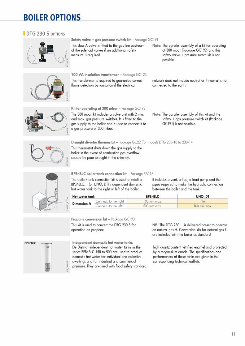
BPB/BLC boiler/tank connection kit – Package EA118The boiler/tank connection kit is used to install a BPB/BLC… (or UNO, DT) independent domestic hot water tank to the right or left of the boiler.
It includes a vent, a flap, a load pump and the pipes required to make the hydraulic connection between the boiler and the tank.
Hot water tank BPB/BLC UNO, DT
Dimension AConnect. to the right 100 mm max. NoConnect. to the left 500 mm max. 100 mm max.
Independent domestic hot water tanksDe Dietrich independent hot water tanks in the series BPB/BLC 150 to 500 are used to produce domestic hot water for individual and collective dwellings and for industrial and commercial premises. They are lined with food safety standard
high quartz content vitrified enamel and protected by a magnesium anode. The specifications and performances of these tanks are given in the corresponding technical leafllets.
BPB/BLC…
BPB_
Q00
01A
12
BOILER OPTIONS
8358
Q00
9
Circuit separation transformer – Package GD122A circuit separation transformer (160 VA) is required if the electrical network does not include neutral or if neutral is not connected to the earth.The circuit separation transformer is fitted under the boiler control panel.
NB: The use of a circuit separation transformer does not modify the boiler insulation class (class I).
DTG 330 S OPTIONS
8358
Q01
6
Cyclical sealing control kit – Package DP92We recommend installing this system when the boiler room is not equipped with a gas detection system.Its role is to check that the seal on the gas solenoid valves is correct before burner start-up or before boiler start-up after a prolonged shutdown. When
the test is positive, the kit control box authorises the provision of electricity to the control circuit. If there is a leak, the control box does not authorise this provision to the control circuit and the boiler remains on stand-by.
8358
Q01
5
Draught diverter thermostat – Package DP89This thermostat shuts down the gas supply to the boiler in the event of combustion gas overflow caused by poor draught in the chimney.
8535
Q00
8
Motorised valve (assembly downstream of the draft diverter)The electrical connection of the motorised valve is made to the connector provided for this purpose in the control panel.
For boiler type Package no.DTG 330-8 to 330-9 GD95
DTG 330-10 to 330-12 GD96DTG 330-14 to 330-18 GD97
DTG 330-20 GD153
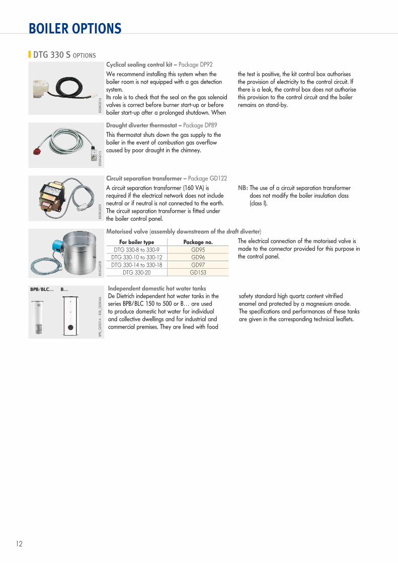
Independent domestic hot water tanksDe Dietrich independent hot water tanks in the series BPB/BLC 150 to 500 or B… are used to produce domestic hot water for individual and collective dwellings and for industrial and commercial premises. They are lined with food
safety standard high quartz content vitrified enamel and protected by a magnesium anode. The specifications and performances of these tanks are given in the corresponding technical leaflets.
BPB/BLC… B…
BPB_
Q00
01A
- RS
B_Q
0004
A
13
INFORMATIONS REQUIRED FOR INSTALLATION
INSTALLATION IN BOILER ROOMS
VentilationThis must comply with prevailing national regulationsExamples (valid in France):Top and bottom ventilation mandatory- Top ventilation:
Cross section equal to half of the total cross section of the flue gas conduits with a minimum of 2.5 dm2.
- Bottom ventilation: Direct air inlet: S (dm2) 0.86 P
20P = Installed output in kW
The air inlets must be located in such a way in relation to the top ventilation vents that air is renewed in the entire volume of the boiler room.
In order to avoid damage to boilers, it is necessary to prevent the contamination of combustion air by chloride and/or fluoride compounds, which are particularly corrosive.
These compounds are present, for example, in aerosol spray cans, paints, solvents, cleaning products, washing powders/liquids, detergents, glues, snow clearing salts, etc.It is therefore necessary:- To avoid sucking in air discharged from premises using
such products: hairdressers, dry cleaners, industrial premises (solvents), premises containing refrigeration systems (risk of leaking refrigeration fluid), etc.
- To avoid the storage of such products close to boilers.Please note that, if the boiler and/or its peripherals become corroded by chloride and/or fluoride compounds, our contractual warranty cannot be invoked.
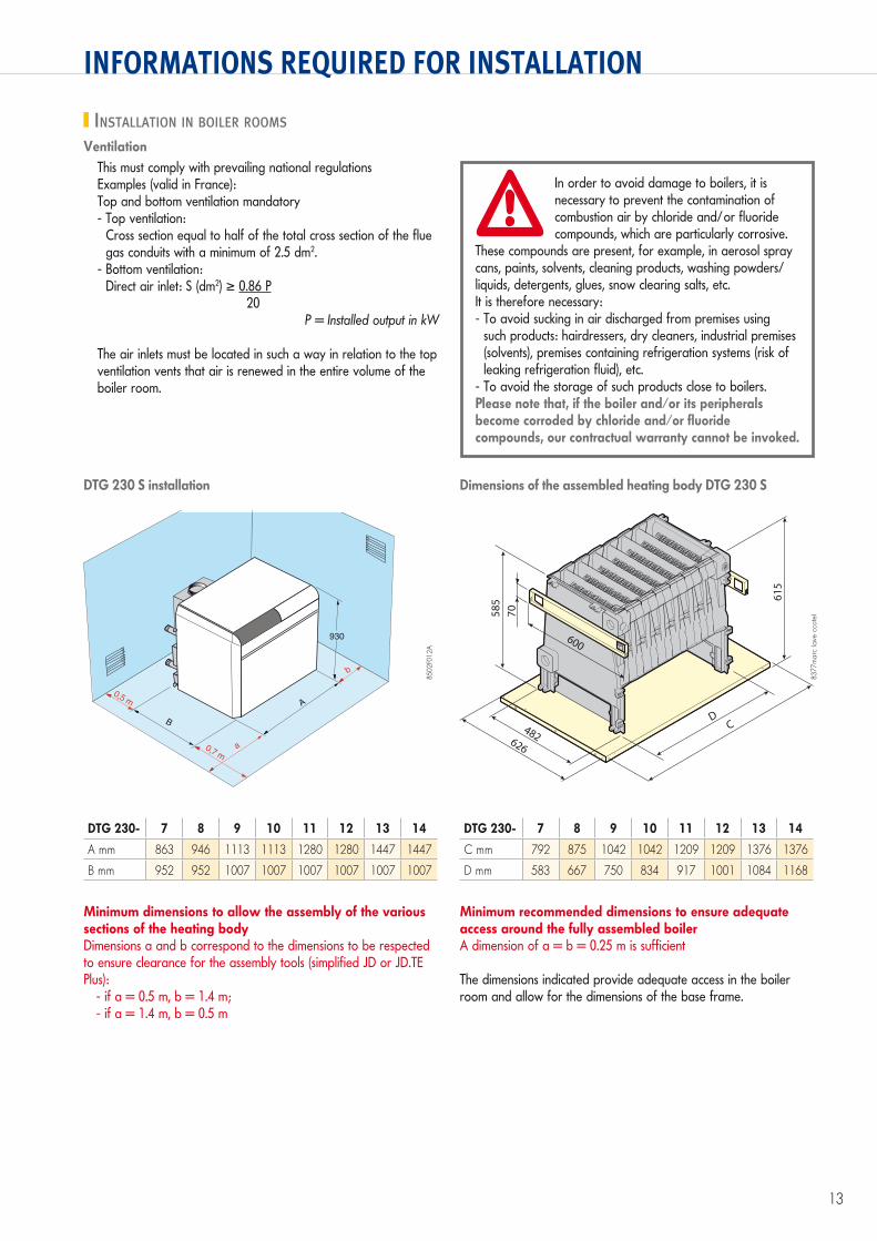
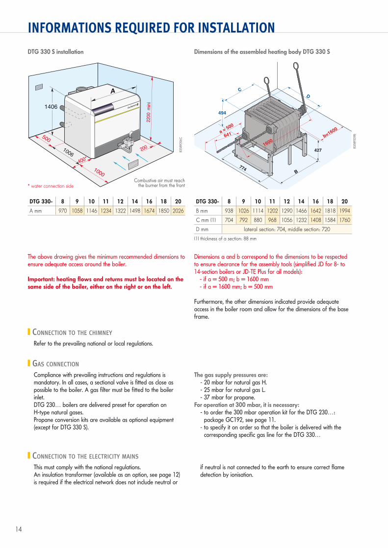
DTG 230 S installation Dimensions of the assembled heating body DTG 230 S
A
a
b
B
0,5 m
0,7 m
930
C
615
626
D
70585
482
600
8502
F012
A
8377
mar
c (a
ve c
cote
)
Minimum dimensions to allow the assembly of the various sections of the heating bodyDimensions a and b correspond to the dimensions to be respected to ensure clearance for the assembly tools (simplified JD or JD.TE Plus):
- if a = 0.5 m, b = 1.4 m;- if a = 1.4 m, b = 0.5 m
Minimum recommended dimensions to ensure adequate access around the fully assembled boilerA dimension of a = b = 0.25 m is sufficient
The dimensions indicated provide adequate access in the boiler room and allow for the dimensions of the base frame.
DTG 230- 7 8 9 10 11 12 13 14
A mm 863 946 1113 1113 1280 1280 1447 1447
B mm 952 952 1007 1007 1007 1007 1007 1007
DTG 230- 7 8 9 10 11 12 13 14
C mm 792 875 1042 1042 1209 1209 1376 1376
D mm 583 667 750 834 917 1001 1084 1168
14
INFORMATIONS REQUIRED FOR INSTALLATION
CONNECTION TO THE CHIMNEY
GAS CONNECTION
CONNECTION TO THE ELECTRICITY MAINS
Refer to the prevailing national or local regulations.
Compliance with prevailing instructions and regulations is mandatory. In all cases, a sectional valve is fitted as close as possible to the boiler. A gas filter must be fitted to the boiler inlet.DTG 230… boilers are delivered preset for operation onH-type natural gases.Propane conversion kits are available as optional equipment (except for DTG 330 S).
The gas supply pressures are:- 20 mbar for natural gas H.- 25 mbar for natural gas L.- 37 mbar for propane.
For operation at 300 mbar, it is necessary:- to order the 300 mbar operation kit for the DTG 230…:
package GC192, see page 11.- to specify it on order so that the boiler is delivered with the
corresponding specific gas line for the DTG 330…
This must comply with the national regulations.An insulation transformer (available as an option, see page 12) is required if the electrical network does not include neutral or
if neutral is not connected to the earth to ensure correct flame detection by ionisation.
DTG 330 S installation Dimensions of the assembled heating body DTG 330 S
500
1006
1000
400*
200 2
20
0
min
i
A
1406
a = 500
641 b=1600
B
C
494
774
D
4271600
8358
F006
C
8358
F009
B
The above drawing gives the minimum recommended dimensions to ensure adequate access around the boiler.
Important: heating flows and returns must be located on the same side of the boiler, either on the right or on the left.
Dimensions a and b correspond to the dimensions to be respected to ensure clearance for the assembly tools (simplified JD for 8- to 14-section boilers or JD-TE Plus for all models):
- if a = 500 m; b = 1600 mm- if a = 1600 mm; b = 500 mm
Furthermore, the other dimensions indicated provide adequate access in the boiler room and allow for the dimensions of the base frame.
DTG 330- 8 9 10 11 12 14 16 18 20
A mm 970 1058 1146 1234 1322 1498 1674 1850 2026
DTG 330- 8 9 10 11 12 14 16 18 20
B mm 938 1026 1114 1202 1290 1466 1642 1818 1994
C mm (1) 704 792 880 968 1056 1232 1408 1584 1760
D mm lateral section: 704, middle section: 720
(1) thickness of a section: 88 mm
* water connection sideCombustive air must reach
the burner from the front
15
INFORMATIONS REQUIRED FOR INSTALLATION
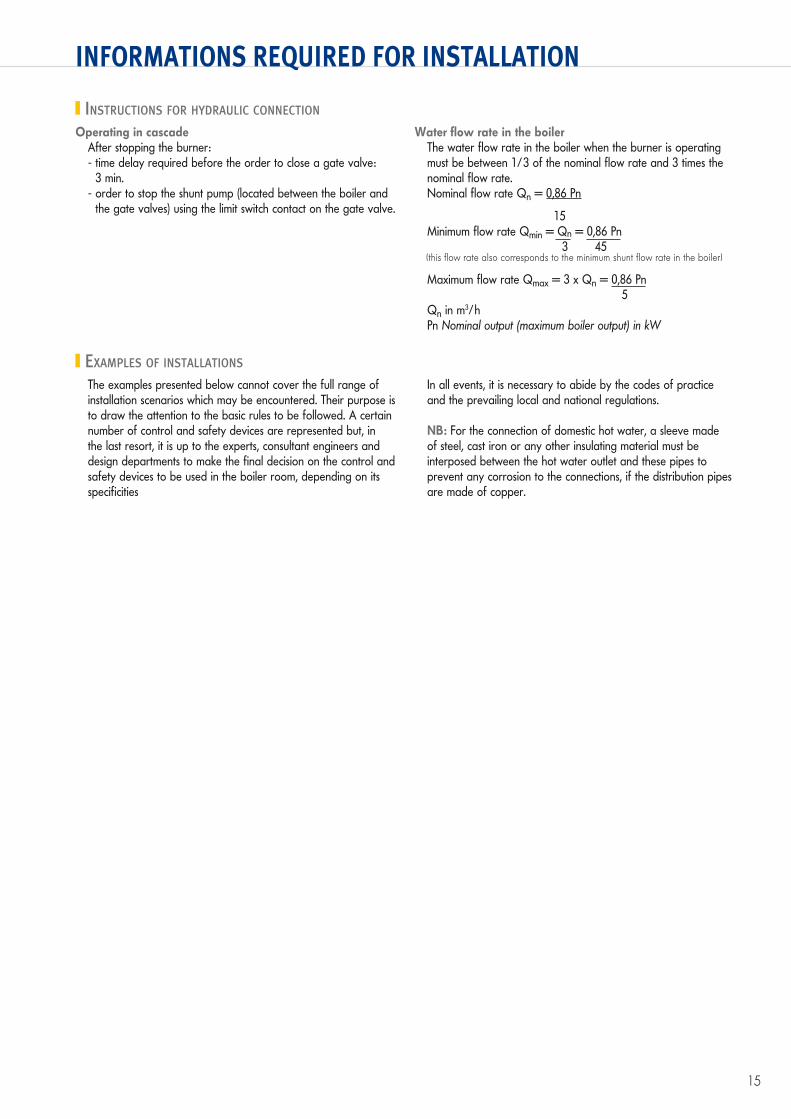
INSTRUCTIONS FOR HYDRAULIC CONNECTION
EXAMPLES OF INSTALLATIONS
Operating in cascadeAfter stopping the burner:- time delay required before the order to close a gate valve:
3 min.- order to stop the shunt pump (located between the boiler and
the gate valves) using the limit switch contact on the gate valve.
Water flow rate in the boilerThe water flow rate in the boiler when the burner is operating must be between 1/3 of the nominal flow rate and 3 times the nominal flow rate.Nominal flow rate Qn = 0,86 Pn
15Minimum flow rate Qmin = Qn = 0,86 Pn 3 45(this flow rate also corresponds to the minimum shunt flow rate in the boiler)
Maximum flow rate Qmax = 3 x Qn = 0,86 Pn 5Qn in m3/hPn Nominal output (maximum boiler output) in kW
The examples presented below cannot cover the full range of installation scenarios which may be encountered. Their purpose is to draw the attention to the basic rules to be followed. A certain number of control and safety devices are represented but, in the last resort, it is up to the experts, consultant engineers and design departments to make the final decision on the control and safety devices to be used in the boiler room, depending on its specificities
In all events, it is necessary to abide by the codes of practice and the prevailing local and national regulations.
NB: For the connection of domestic hot water, a sleeve made of steel, cast iron or any other insulating material must be interposed between the hot water outlet and these pipes to prevent any corrosion to the connections, if the distribution pipes are made of copper.

16
EXAMPLES OF INSTALLATIONS
DTG 230 B3 with 1 direct circuit + 1 domestic hot water circuit(Schematic valid by analogy for a DTG 330 B3)
DTG 230 DIEMATIC-m3 with 3 circuits with mixing valve + 1 domestic hot water circuit, all behind a decoupling cylinder(Schematic valid by analogy for a DTG 330 DIEMATIC-m3)
29
30
28
9
7
3324
25
329
9
27
27
26
9 9
AD 212
17 16
21
9
34
5
1
7
2
51
99
5211
27
°C °C
B3
230 V / 50 Hz
50
189
29
30
28
9
7
3324
25
329
9
27
27
26
9 9
50
189
65
99
5211
10
27
27 27
°C °C
23
44
4
65
99
5211
10
27
27
°C °C
23
44
4
°C °C
4
AD199
FM48
FM48 AD 212
17 36
39
16
7
8
13
65
99
5211
10
2723
44
21
9
34
5
1
7
2
Diematic-m3
230 V / 50 Hz
DTG
230_
F000
6
Key on page 17
DTG
230_
F000
7A
17
EXAMPLES OF INSTALLATIONS
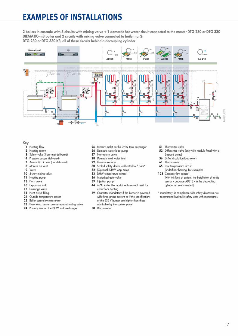
1 Heating flow 2 Heating return 3 Safety valve 3 bar (not delivered) 4 Pressure gauge (delivered) 7 Automatic air vent (not delivered) 8 Manual air vent 9 Valve 10 3-way mixing valve 11 Heating pump 13 Flush valve 16 Expansion tank 17 Drainage valve 18 Heat circuit filling 21 Outside temperature sensor 22 Boiler control system sensor 23 Flow temp. sensor downstream of mixing valve 24 Primary inlet on the DHW tank exchanger
25 Primary outlet on the DHW tank exchanger 26 Domestic water load pump 27 Non-return valve 28 Domestic cold water inlet 29 Pressure reducer 30 Sealed safety device calibrated to 7 bars* 32 (Optional) DHW loop pump 33 DHW temperature sensor 36 Motorised gate valve 39 Injection pump 44 65°C limiter thermostat with manual reset for
underfloor heating 49 Contactor mandatory if the burner is powered
with three-phase current or if the specifications of the 230 V burner are higher than those admissible by the control panel
50 Disconnector
51 Thermostat valve 52 Differential valve (only with module fitted with a
3-speed pump) 56 DHW circulation loop return 61 Thermometer 65 Low temperature circuit
(underfloor heating, for example) 123 Cascade flow sensor
(with this kind of system, the installation of a dip sensor - package AD218 - in the decoupling cylinder is recommended)
* mandatory, in compliance with safety directives: we recommend hydraulic safety units with membranes.
Key
2 boilers in cascade with 3 circuits with mixing valve + 1 domestic hot water circuit connected to the master DTG 230 or DTG 330 DIEMATIC-m3 boiler and 2 circuits with mixing valve connected to boiler no. 2:DTG 230 or DTG 330 K3, all of these circuits behind a decoupling cylinder
29
30
28
9
7
3324
25
329
9
27
27
26
9 9
AD 218
BUS 65
99
5211
10
27
27 27 27 27
°C °C
23 23 23 23
44
4
65
99
5211
10
27
27
°C °C
23
44
4
°C °C
4
°C °C
4
°C °C
4
17 36 36
39 39
16
7
8
13
17
AD199
FM48
AD220
FM48
FM48
65
99
5211
10
27
4465
99
5211
10
27
4465
99
5211
10
27
44
21
9
34
5 5
1
7
2
9
123
34
1
7
2
AD 212
230 V / 50 Hz230 V / 50 Hz
Diematic-m3 K3
50
189
DTG
230_
F000
8

18
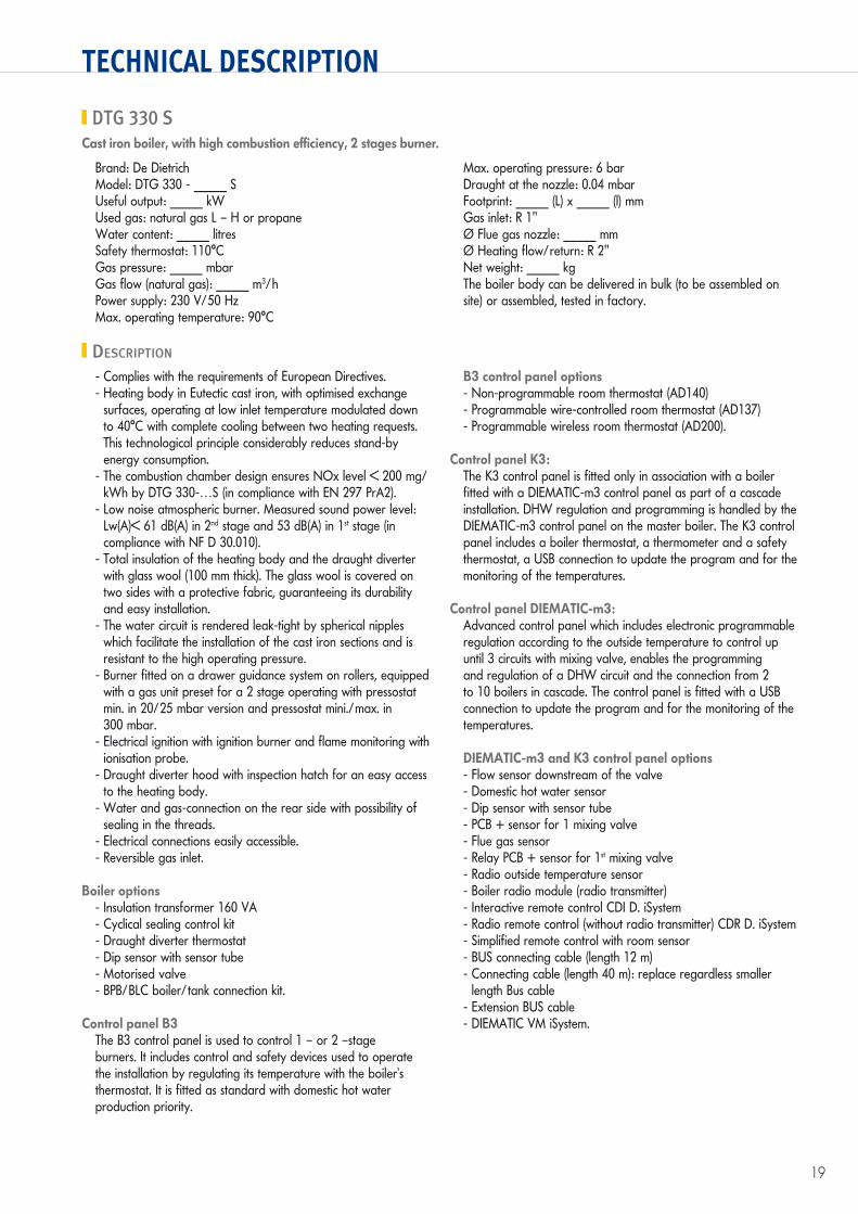
TECHNICAL DESCRIPTION
DTG 230 SCast iron boiler, with high combustion efficiency, 2 stages burner.
Brand: De DietrichModel: DTG 230 - _____ SUseful output: _____ kWUsed gas: natural gas L – H or propaneWater content: _____ litresSafety thermostat: 110°CGas pressure: _____ mbarGas flow (natural gas): _____ m3/hPower supply: 230 V/50 HzMax. operating temperature: 90°C
Max. operating pressure: 6 barDraught at the nozzle: 0.04 mbarFootprint: _____ (L) x _____ (l) mmGas inlet: R 1"Ø Flue gas nozzle: _____ mmØ Heating flow/return: R 1" 1/2Net weight: _____ kgThe boiler body can be delivered in bulk (to be assembled on site) or assembled, tested in factory.
- Complies with the requirements of European Directives.- Heating body in Eutectic cast iron, with optimised exchange
surfaces, operating at low inlet temperature modulated down to 30°C with complete cooling between two heating requests. This technological principle considerably reduces stand-by energy consumption.
- The combustion chamber design ensures NOx level < 200 mg/kWh by DTG 230-…S (in compliance with EN 297 PrA2 for DTG 230-7 and 8 S, in compliance with EN 656 for DTG 230-9 to 14 S).
- Efficiency of 93.2% NCV.- Draught diverter thermostat (DTG 230-7 to 230-9 S).- Low noise atmospheric burner. Measured sound power level (in
compliance with NF D 30.010): Lw(A)=54.0 dB(A) in 1st stage and 57.1 dB(A) in 2nd stage.
- Total insulation of the heating body and the draught diverter with glass wool (100 mm thick). The glass wool is covered on two sides with a protective fabric, guaranteeing its durability and easy installation.
- The water circuit is rendered leak-tight by spherical nipples which facilitate the installation of the cast iron sections and is resistant to the high operating pressure.
- The gas burner is mounted on a guidance system with rollers, equipped with 1 (or 2) preset gas unit(s).
- Electrical ignition with ignition burner and flame monitoring with ionisation probe.
- Draught diverter hood with inspection hatch for an easy access to the heating body.
- Water and gas-connection on the rear side with possibility of sealing in the threads.
- Electrical connections easily accessible.
Boiler options- Insulation transformer 100 VA- Cyclical sealing control kit- Kit for operating at 300 mbar- Draught diverter thermostat- Dip sensor with sensor tube- Propane conversion kit- BPB/BLC boiler/tank connection kit.
Control panel B3The B3 control panel is used to control 1 – or 2 –stage burners. It includes control and safety devices used to operate the installation by regulating its temperature with the boiler’s thermostat. It is fitted as standard with domestic hot water production priority.
B3 control panel options- Non-programmable room thermostat (AD140)- Programmable wire-controlled room thermostat (AD137)- Programmable wireless room thermostat (AD200).
Control panel K3:The K3 control panel is fitted only in association with a boiler fitted with a DIEMATIC-m3 control panel as part of a cascade installation. DHW regulation and programming is handled by the DIEMATIC-m3 control panel on the master boiler. The K3 control panel includes a boiler thermostat, a thermometer and a safety thermostat, a USB connection to update the program and for the monitoring of the temperatures.
Control panel DIEMATIC-m3:Advanced control panel which includes electronic programmable regulation according to the outside temperature to control up until 3 circuits with mixing valve, enables the programming and regulation of a DHW circuit and the connection from 2 to 10 boilers in cascade. The control panel is fitted with a USB connection to update the program and for the monitoring of the temperatures.
DIEMATIC-m3 and K3 control panel options- Flow sensor downstream of the valve- Domestic hot water sensor- Dip sensor with sensor tube- PCB + sensor for 1 mixing valve- Flue gas sensor- Relay PCB + sensor for 1st mixing valve- Radio outside temperature sensor- Boiler radio module (radio transmitter)- Interactive remote control CDI D. iSystem- Radio remote control (without radio transmitter) CDR D. iSystem- Simplified remote control with room sensor- BUS connecting cable (length 12 m)- Connecting cable (length 40 m): replace regardless smaller
length Bus cable- Extension BUS cable- DIEMATIC VM iSystem.
DESCRIPTION
19
TECHNICAL DESCRIPTION
DTG 330 SCast iron boiler, with high combustion efficiency, 2 stages burner.
Brand: De DietrichModel: DTG 330 - _____ SUseful output: _____ kWUsed gas: natural gas L – H or propaneWater content: _____ litresSafety thermostat: 110°CGas pressure: _____ mbarGas flow (natural gas): _____ m3/hPower supply: 230 V/50 HzMax. operating temperature: 90°C
Max. operating pressure: 6 barDraught at the nozzle: 0.04 mbarFootprint: _____ (L) x _____ (l) mmGas inlet: R 1"Ø Flue gas nozzle: _____ mmØ Heating flow/return: R 2"Net weight: _____ kgThe boiler body can be delivered in bulk (to be assembled on site) or assembled, tested in factory.
- Complies with the requirements of European Directives.- Heating body in Eutectic cast iron, with optimised exchange
surfaces, operating at low inlet temperature modulated down to 40°C with complete cooling between two heating requests. This technological principle considerably reduces stand-by energy consumption.
- The combustion chamber design ensures NOx level < 200 mg/kWh by DTG 330-…S (in compliance with EN 297 PrA2).
- Low noise atmospheric burner. Measured sound power level: Lw(A)< 61 dB(A) in 2nd stage and 53 dB(A) in 1st stage (in compliance with NF D 30.010).
- Total insulation of the heating body and the draught diverter with glass wool (100 mm thick). The glass wool is covered on two sides with a protective fabric, guaranteeing its durability and easy installation.
- The water circuit is rendered leak-tight by spherical nipples which facilitate the installation of the cast iron sections and is resistant to the high operating pressure.
- Burner fitted on a drawer guidance system on rollers, equipped with a gas unit preset for a 2 stage operating with pressostat min. in 20/25 mbar version and pressostat mini./max. in 300 mbar.
- Electrical ignition with ignition burner and flame monitoring with ionisation probe.
- Draught diverter hood with inspection hatch for an easy access to the heating body.
- Water and gas-connection on the rear side with possibility of sealing in the threads.
- Electrical connections easily accessible.- Reversible gas inlet.
Boiler options- Insulation transformer 160 VA- Cyclical sealing control kit- Draught diverter thermostat- Dip sensor with sensor tube- Motorised valve- BPB/BLC boiler/tank connection kit.
Control panel B3The B3 control panel is used to control 1 – or 2 –stage burners. It includes control and safety devices used to operate the installation by regulating its temperature with the boiler’s thermostat. It is fitted as standard with domestic hot water production priority.
B3 control panel options- Non-programmable room thermostat (AD140)- Programmable wire-controlled room thermostat (AD137)- Programmable wireless room thermostat (AD200).
Control panel K3:The K3 control panel is fitted only in association with a boiler fitted with a DIEMATIC-m3 control panel as part of a cascade installation. DHW regulation and programming is handled by the DIEMATIC-m3 control panel on the master boiler. The K3 control panel includes a boiler thermostat, a thermometer and a safety thermostat, a USB connection to update the program and for the monitoring of the temperatures.
Control panel DIEMATIC-m3:Advanced control panel which includes electronic programmable regulation according to the outside temperature to control up until 3 circuits with mixing valve, enables the programming and regulation of a DHW circuit and the connection from 2 to 10 boilers in cascade. The control panel is fitted with a USB connection to update the program and for the monitoring of the temperatures.
DIEMATIC-m3 and K3 control panel options- Flow sensor downstream of the valve- Domestic hot water sensor- Dip sensor with sensor tube- PCB + sensor for 1 mixing valve- Flue gas sensor- Relay PCB + sensor for 1st mixing valve- Radio outside temperature sensor- Boiler radio module (radio transmitter)- Interactive remote control CDI D. iSystem- Radio remote control (without radio transmitter) CDR D. iSystem- Simplified remote control with room sensor- BUS connecting cable (length 12 m)- Connecting cable (length 40 m): replace regardless smaller
length Bus cable- Extension BUS cable- DIEMATIC VM iSystem.
DESCRIPTION

DE DIETRICH THERMIQUES.A.S. with corporate capital of 22 487 610 €57, rue de la Gare - F-67580 MERTZWILLERTel. +33 3 88 80 27 00 - Fax +33 3 88 80 27 99www.dedietrich-heating.com
10/2
016
– 30
0014
063B
– 3
47.5
55.5
59 S
trasb
ourg
Com
pani
es R
egist
er –
Doc
umen
t not
con
tract
ually
bin
ding
- Pr
inte
d in
Fra
nce
- OTT
Impr
imeu
rs 6
7310
Was
selo
nne
- 162
849
SUSTAINABLE COMFORT®
Top Related