


Languages
Pages
Legal


Technical Data 60 HzVertical centrifugal pumps
Series: DPVE / DPV(S) / DPVCF / DPLHS
DPVE DPV(S) DPVCF DPLHS

2
Table of Contents
1 Pump introduction1.1 General .................................................................................................................................................. 41.2 Model key............................................................................................................................................... 41.3 Description of the product ...................................................................................................................... 51.4 Operation ............................................................................................................................................... 51.5 Working range........................................................................................................................................ 5
2 Performance characteristics2.1 Performance curve details ..................................................................................................................... 72.2 Performance with variable frequency drive............................................................................................ 82.3 Performance characteristics DPVE 2-pole 60 Hz .................................................................................. 92.4 Performance characteristics DPV(S)(F) 2-pole 60 Hz ........................................................................... 92.5 Performance characteristics DPV(S)(F) 4-pole 60 Hz ......................................................................... 102.6 Performance characteristics DPVCF 2-pole 60 Hz.............................................................................. 10
3 Technical specifications3.1 Dimensions and weights DPVE 2 60 Hz.............................................................................................. 123.2 Hydraulic performance DPVE 2 60 Hz ª3500 1/min ............................................................................ 133.3 Dimensions and weights DPVE 4 60 Hz.............................................................................................. 143.4 Hydraulic performance DPVE 4 60 Hz ª3500 1/min ............................................................................ 153.5 Dimensions and weights DPV(S) 2 60 Hz ........................................................................................... 163.6 Hydraulic performance DPV(S) 2 60 Hz ª3500 1/min .......................................................................... 173.7 Dimensions and weights DPV(S) 4 60 Hz ........................................................................................... 183.8 Hydraulic performance DPV(S) 4 60 Hz ª3500 1/min .......................................................................... 193.9 Dimensions and weights DPV(S) 10 60 Hz ......................................................................................... 203.10 Hydraulic performance DPV(S) 10 60 Hz ª3500 1/min ........................................................................ 213.11 Dimensions and weights DPV(S) 14 60 Hz ......................................................................................... 223.12 Hydraulic performance DPV(S) 14 60 Hz ª1750 1/min ........................................................................ 233.13 Dimensions and weights DPV(S) 18 60 Hz ......................................................................................... 243.14 Hydraulic performance DPV(S) 18 60 Hz ª3500 1/min ........................................................................ 253.15 Dimensions and weights DPV(S)F 24 60 Hz ....................................................................................... 263.16 Hydraulic performance DPV(S)F 24 60 Hz ª1750 1/min...................................................................... 273.17 Dimensions and weights DPV(S)F 32 60 Hz ....................................................................................... 283.18 Hydraulic performance DPV(S)F 32 60 Hz ª3500 1/min...................................................................... 293.19 Dimensions and weights DPV(S)F 45 60 Hz ....................................................................................... 303.20 Hydraulic performance DPV(S)F 45 60 Hz ª3500 1/min...................................................................... 313.21 Dimensions and weights DPV(S)F 65 60 Hz ....................................................................................... 323.22 Hydraulic performance DPV(S)F 65 60 Hz ª3500 1/min...................................................................... 333.23 Dimensions and weights DPLHS 6 60 Hz............................................................................................ 34
3
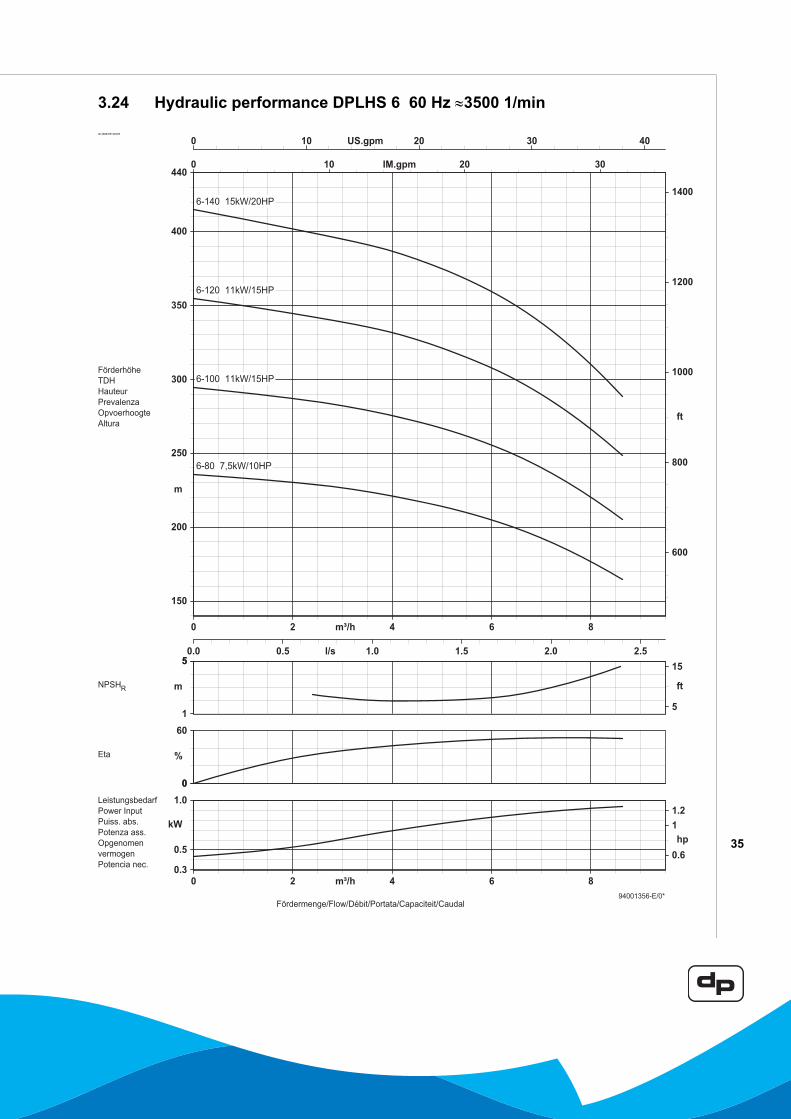
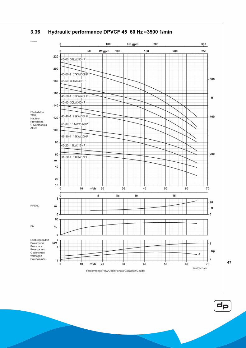
3.24 Hydraulic performance DPLHS 6 60 Hz ª3500 1/min .......................................................................... 353.25 Dimensions and weights DPVCF 2 60 Hz ........................................................................................... 363.26 Hydraulic performance DPVCF 2 60 Hz ª3500 1/min .......................................................................... 373.27 Dimensions and weights DPVCF 4 60 Hz ........................................................................................... 383.28 Hydraulic performance DPVCF 4 60 Hz ª3500 1/min .......................................................................... 393.29 Dimensions and weights DPVCF 10 60 Hz ......................................................................................... 403.30 Hydraulic performance DPVCF 10 60 Hz ª3500 1/min ........................................................................ 413.31 Dimensions and weights DPVCF 18 60 Hz ......................................................................................... 423.32 Hydraulic performance DPVCF 18 60 Hz ª3500 1/min ........................................................................ 433.33 Dimensions and weights DPVCF 32 60 Hz ......................................................................................... 443.34 Hydraulic performance DPVCF 32 60 Hz ª3500 1/min ........................................................................ 453.35 Dimensions and weights DPVCF 45 60 Hz ......................................................................................... 463.36 Hydraulic performance DPVCF 45 60 Hz ª3500 1/min ........................................................................ 473.37 Dimensions and weights DPVCF 65 60 Hz ......................................................................................... 483.38 Hydraulic performance DPVCF 65 60 Hz ª3500 1/min ........................................................................ 49
4 Materials4.1 Overview of materials .......................................................................................................................... 504.2 Materials conversion ............................................................................................................................ 504.3 Mechanical seal specifications............................................................................................................. 51
5 Connections5.1 Suction and discharge connections (standard G and DIN).................................................................. 525.2 Suction and discharge connections (optional ASME) .......................................................................... 535.3 Suction and discharge connections (optional Rc and JIS)................................................................... 54
6 Factory options6.1 Factory options .................................................................................................................................... 55
7 Accessories7.1 Horizontal mounting kit ........................................................................................................................ 567.2 Thrust bearing housing ........................................................................................................................ 57
8 Sectional drawings8.1 Parts list ............................................................................................................................................... 588.2 Sectional drawing DPVE 2/4................................................................................................................ 598.3 Sectional drawing DPV(S) 2/4/10/14/18 .............................................................................................. 608.4 Sectional drawing DPV(S)F 24/32 ....................................................................................................... 618.5 Sectional drawing DPV(S)F 24/32 with cartridge seal ......................................................................... 628.6 Sectional drawing DPV(S)F 45 ............................................................................................................ 638.7 Sectional drawing DPV(S)F 45 with cartridge seal .............................................................................. 648.8 Sectional drawing DPV(S)F 65 ............................................................................................................ 658.9 Sectional drawing DPLHS 6................................................................................................................. 668.10 Sectional drawing DPVCF 2/4/10/18 ................................................................................................... 678.11 Sectional drawing DPVCF 32 .............................................................................................................. 688.12 Sectional drawing DPVCF 32 with cartridge seal ................................................................................ 698.13 Sectional drawing DPVCF 45 .............................................................................................................. 708.14 Sectional drawing DPVCF 45 with cartridge seal ................................................................................ 718.15 Sectional drawing DPVCF 65 .............................................................................................................. 72

4
1 Pump introduction
1.1 General
The vertical, multi-stage centrifugal pumps DPVE, DPV(S), DPVCF and DPLHS are produced by DP-Pumps.
1.2 Model key
ID 2543/07072006
2004
0265
-B
DPVE DPV(S) DPVCF DPLHS
Pump type DPVS F 45 -50 -1Materials DPV DP Vertical pumps in AISI 304 (1.4301).
DPVE DP Vertical pumps in AISI 304 (1.4301). Male thread with built-in non-return valve on discharge side.
DPVS DP Vertical pump in superior grade AISI 316 (1.4401).DPLHS DP Vertical pump in superior grade AISI 316 (1.4401) 40 Bar.DPVCF DP Vertical pump with cast-iron pumpcasing for heavy duty applications.
Pump connections Oval counterflanges with female thread (DPLHS round flanges)F Round flanges DIN, JIS or ASME.V Victaulic connection.
Model / flow 45 Pump model indicates nominal flow in [m3/h].Stages / head -50 Indicates number of impeller stages (50 = 5).Half stage impeller -1 Fitted with a half stage impeller (only DPV(S)F 45

5
1.3 Description of the product
The vertical, single or multistage pump series DPV, DPVE, DPLHS and DPVCF are designed for pumping clean, watery liquids. Suction and discharge of the pump are in-line, making the pump easy to install. The hydraulic assembly is installed vertically and driven by an electric motor.
All hydraulic parts of the pump (except for the suction/discharge casing of the DPVCF) are made of stainless steel, making the pump light and extremely suitable for applications that demand high grade materials, such as drinking water applications.
The DPV series is the standard vertical pump, available in various types. The DPVE is a compact vertical pump with a built-in non-return valve, especially designed for drinking water applications. The DPLHS is designed for high pressures (up to 40 Bar) and the DPVCF is designed for industrial, heavy duty applications, such as boiler feed.
The pump is initially designed for vertical installation, but can be installed horizontally by using a special adaptation set.
1.4 Operation
The liquid is sucked in through the pump inlet (A) on the supply side under minimum pressure. The pump increases the pressure. The liquid leaves the pump through the pump outlet (B) on the delivery side under increased pressure.
A Pump inletB Pump outletC Terminal boxD Fill plug/air relief plugE Drain plug
1.5 Working range
The working range of the pumps in this series can be summarised as follows:
ID 0304/02072003
0304
/020
7200
3
ID 2458/07052004
2458
/070
5200
4
A
C
D
BE
AB

6
Table 1: Specification of the working range
Minimum volume flows (Q) in % of Q optimum temperatures (t).Table 2: Minimum volume flows (Qmin)
Table 3: Specific applications
Pump type
DPV
E
DPV
DPV
F/V
DPV
S
DPV
SF/V
DPV
CF
DPL
HS
Ambient tempera-ture [°C]
+4 to 40
Liquid tem-perature [°C]
-15 to 60
-15 to 1001
1. Using the factory option “o-ring sealing EPDM E425” the max. temp. limit is 120°C.
-15 to 1202
2. When pumping water, the max. allowable liquid temp is 80°C.
-15 to 120
-15 to 803
3. Higher temperatures are possible at lower pressure. For specific limits consult your supplier.
Maximum working pressure [bar]
104
4. The total of the supply pressure and no-load delivery pressure with closed outlet shut-off valve may not exceed the maximum working pressure.
164 254 164 254 254 404
Allowable size of solids pumped
5µ to 1mm
Minimum supply pressure
Not cavitating5.
5. Contact your supplier for more detailed advice.
Viscosity liquid [cSt]
1A higher viscosity may require more motor
power.5
Density liq-uid [kg/m3]
1000A higher density may require more motor
power.5
Cooling The space above the cooling fan of the motor must at least be equal to 1/4 of the diameter of the inlet of the cooling fan of the motor in
order to have a sufficient supply of air.Number of starts
Related to the motor6
6. For standard motors see the technical specifications. When the pump is fitted with another motor brand, please consult the motor supplier.
Minimum frequency [Hz]
10
Maximum frequency [Hz]
607
7. Pumps that are intended for 50 Hz operation, may not be connected to 60 Hz.
DP 50 Hz 60 HzQmin in m3/h
2 0,3 0,34 0,6 0,656 0,8 0,810 1,2 1,414 1,0 1,118 2,4 2,424 2,2 2,632 4,0 4,045 4,6 5,165 6,1 6,1
type application areaDPV (Drinking) water supply systems, irrigation
systems, water treatment systems, car-wash systems, sprinkler systems.
DPVS Water-supply systems for drinking water, softened and demineralised water, systems for brackish water, sea water and swim-ming-pool water, however limited with respect to temperature, pressure and chlo-rine percentage.
DPVCF Systems for boiler supply and discharge of condensed water
DPLHS Reverse osmosis installations and high pressure cleaning systems.
DPVE (Drinking) water supply systems.
40 50 60 70 80 90 100 110 120
0
10
5
15
20
25
30
t [°C]
Q [%
]

7
2 Performance characteristics
2.1 Performance curve details
The preceding diagrams give a global overview of all the pump models mentioned in this documentation. Detailed characteristics are given for each model showing the hydraulic efficiency, NPSHreq, and shaft power as well.
The performance of the pump depends on the number of stages. The number of stages are shown as a multiple of 10, as per example:
The detailed performance curves are in accordance with ISO 9906 Annex A. Vibration limits at rated speed and rated flow are according to ISO 9905.
The motors used for the measurements are standard DP. When using another motor brand the performance data, like Q/H, efficiency and shaft power must be corrected accordingly.
The characteristics given are based on:• Deaerated water at a temperature of 20 °C• Density of 1,0 kg/dm3
• Kinematical viscosity of 1 mm2/s (1 cst)
To prevent the pump from overheating, gathering gas, cavitations etc. a minimum flow has to be secured.The minimum flow corresponds to a percentage of the optimum flow Qopt in relation to the temperature of the liquid pumped.
DPV 10-60 6 full stage impellersDPVF 45-50-1 5 full stage impellers and 1 half stage
impeller

8
2.2 Performance with variable frequency drive
The minimum frequency of the DP motor should be limited to 10 Hz to ensure sufficient cooling. When the rotational speed exceeds the nominal speed of the motor, make sure that the power output of the motor is suitable to drive the corresponding pump model.
The converted frequency from an average variable frequency drive will have a rather high pulse rise time, which creates heat in the winding. To be suitable for this kind of application, the DP motors are built in accordance with IEC 60034-17.
ID 2575/11042005
2575
/110
4200
5

9
2.3 Performance characteristics DPVE 2-pole 60 Hz
2.4 Performance characteristics DPV(S)(F) 2-pole 60 Hz
ID 2811/07062006
2811
/070
6200
6
n=
35001/m
in
5 10 20 30 40US.gpm
4 5 10 20 30IM.gpm
0.3 0.4 0.5 1 2l/s
1 2 3 4 5 10Q[m /h]310
20
30
40
50
100
ft
3
4
5
10
20
30
40
50
60
H[m]
DPVE 2DPVE 4
ID 2803/07062006
2803
/070
6200
6n=
35001/m
in
5 10 20 30 40 50 100 200 300 400US.gpm
4 5 10 20 30 40 50 100 200 300IM.gpm
0.3 0.4 0.5 1 2 3 4 5 10 20l/s
1 2 3 4 5 10 20 30 40 50 100Q[m /h]310
20
30
40
50
100
200
300
400
500
1000
ft
3
4
5
10
20
30
40
50
100
200
300
400
500
H[m]
DPV(S) 2
DPV(S) 4
DPV(S) 10
DPLHS 6
DPV(S) 18
DPV(S)F 32
DPV(S)F 45
DPV(S)F 65

10
2.5 Performance characteristics DPV(S)(F) 4-pole 60 Hz
2.6 Performance characteristics DPVCF 2-pole 60 Hz
ID 2801/07062006
2801
/070
6200
6
n=
17501/m
in
5 10 20 30 40 50 100US.gpm
4 5 10 20 30 40 50 100IM.gpm
0.3 0.4 0.5 1 2 3 4 5 10l/s
1 2 3 4 5 10 20 30 40Q[m /h]310
20
30
40
50
100
200
300
400
500
ft
3
4
5
10
20
30
40
50
100
200
H[m]
DPV(S) 14
DPV(S)F 24
ID 2805/26042007
2805
/260
4200
7

11
3 Technical specifications

12
3.1 Dimensions and weights DPVE 2 60 Hz
ID 2744/05122005
DPVE 2 9500
0714
DPVE 2 60 Hz General
Mod
el
P [k
W]
P [H
P]
E1 [m
m]
E2 [m
m]
F1 [m
m]
Net
wei
ght
[kg]
2- 10 0,37 0.5 134 107 413 132- 20 0,37 0.5 134 107 413 132- 30 0,55 0.75 134 107 458 152- 40 0,75 1 150 115 470 18
20020512-C

13
3.2 Hydraulic performance DPVE 2 60 Hz ≈3500 1/minID 2728/05122005

14
3.3 Dimensions and weights DPVE 4 60 Hz
ID2750/05122005
DPVE 4 9500
0715
DPVE 4 60 Hz GeneralModel
P [k
W]
P [H
P]
E1 [m
m]
E2 [m
m]
F1 [m
m]
Net
wei
ght
[kg]
4- 10 0,37 0.5 134 107 413 134- 20 0,55 0.75 134 107 437 154- 30 0,75 1 150 115 449 184- 40 1,1 1.5 150 115 500 20
20020514-C

15
3.4 Hydraulic performance DPVE 4 60 Hz ≈3500 1/minID 2730/05122005

16
3.5 Dimensions and weights DPV(S) 2 60 Hz
ID 2741/05122005
DPV(S) 2
ID 2743/05122005
DPV(S)V 2
9500
0714
ID 2742/05122005
DPV(S)F 2
DPV(S)(V)(F) 2 60 Hz General DPV(S) DPV(S)V DPV(S)F
Mod
el
P [k
W]
P [H
P]
E1 [m
m]
E2 [m
m]
F1 [m
m]
F2 [m
m]
Net
wei
ght
[kg]
F1 [m
m]
F2 [m
m]
Net
wei
ght
[kg]
F1 [m
m]
F2 [m
m]
Net
wei
ght
[kg]
2- 10 0,37 0.5 134 107 451 232 13 451 232 13 476 257 142- 20 0,37 0.5 134 107 451 232 13 451 232 13 476 257 142- 30 0,55 0.75 134 107 496 253 16 496 253 16 521 278 162- 40 0,75 1 150 115 518 284 19 518 284 19 543 309 202- 50 1,1 1.5 150 115 569 305 21 569 305 21 594 330 212- 60 1,1 1.5 150 115 590 326 21 590 326 21 615 351 222- 70 1,5 2 176 136 632 357 25 632 357 25 657 382 262- 80 1,5 2 176 136 653 378 26 653 378 26 678 403 262- 90 1,5 2 176 136 674 399 26 674 399 26 699 424 272- 100 2,2 3 176 136 695 420 30 695 420 30 720 445 302- 110 2,2 3 176 136 x x x 716 441 30 741 466 312- 130 2,2 3 176 136 x x x 758 483 31 783 508 322- 150 3 4 194 147 x x x 851 535 42 876 560 432- 160 3 4 194 147 x x x 872 556 43 897 581 432- 180 4 5 233 162 x x x 922 598 52 947 623 53
96000823-K
17
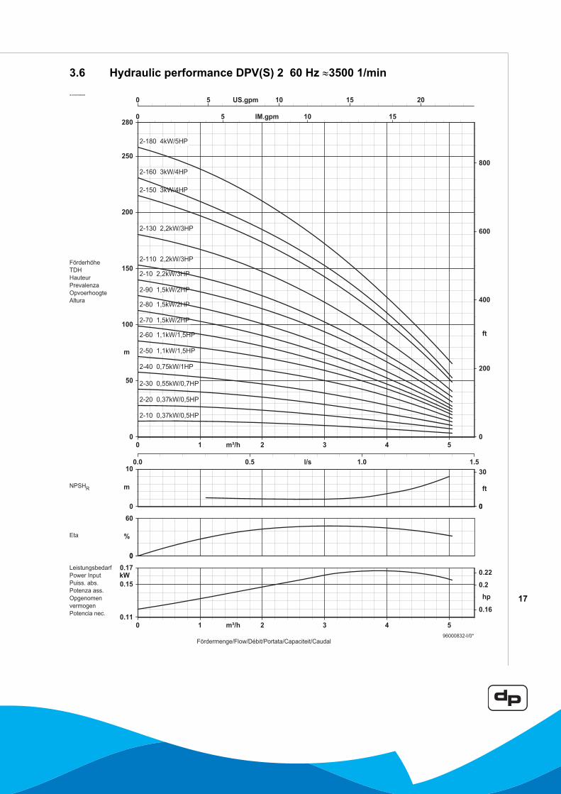
3.6 Hydraulic performance DPV(S) 2 60 Hz ≈3500 1/minID 2700/07062006

18
3.7 Dimensions and weights DPV(S) 4 60 Hz
ID 2745/05122005
DPV(S) 4
ID 2748/05122005
DPV(S)V 4
9500
0715
ID 2747/05122005
DPV(S)F 4
DPV(S)(V)(F) 4 60 Hz General DPV(S) DPV(S)V DPV(S)FModel
P [k
W]
P [H
P]
E1 [m
m]1
E2 [m
m]
F1 [m
m]
F2 [m
m]
Net
wei
ght
[kg]
F1 [m
m]
F2 [m
m]
Net
wei
ght
[kg]
F1 [m
m]
F2 [m
m]
Net
wei
ght
[kg]
4- 10 0,37 0.5 134 107 451 232 13 451 232 13 476 257 154- 20 0,55 0.75 134 107 475 232 15 475 232 15 500 257 174- 30 0,75 1 150 115 497 263 19 497 263 19 522 288 204- 40 1,1 1.5 150 115 548 284 20 548 284 20 573 309 224- 50 1,5 2 176 136 590 315 24 590 315 24 615 340 264- 60 1,5 2 176 136 611 336 25 611 336 25 636 361 264- 70 2,2 3 176 136 632 357 28 632 357 28 657 382 304- 80 2,2 3 176 136 653 378 29 653 378 29 678 403 304- 90 3 4 194 147 725 409 39 725 409 39 750 434 414- 100 3 4 194 147 746 430 40 746 430 40 771 455 414- 110 3 4 194 147 x x x 767 451 40 792 476 424- 130 4 5 233 162 x x x 817 493 50 842 518 524- 150 4 5 233 162 x x x 859 535 51 884 560 534- 160 5,5 7.5 233 162 x x x 885 556 58 910 581 59
96000824-M
1. Diameter adapter flange 5,5-7,5 kW = 300 mm, 11-22 kW = 350 mm, 30-37 kW = 400 mm

19
3.8 Hydraulic performance DPV(S) 4 60 Hz ≈3500 1/minID 2702/05122005

20
3.9 Dimensions and weights DPV(S) 10 60 Hz
ID 2751/05122005
DPV(S) 10
ID 2753/05122005
DPV(S)V 10
9700
0191
ID 2752/05122005
DPV(S)F 10
DPV(S)(V)(F) 10 60 Hz General DPV(S) DPV(S)V DPV(S)F
Mod
el
P [k
W]
P [H
P]
E1 [m
m]1
E2 [m
m]
F1 [m
m]
F2 [m
m]
Net
wei
ght
[kg]
Net
wei
ght
[kg]
Net
wei
ght
[kg]
10- 10 0,75 1 150 115 556 322 23 23 2610- 20 1,5 2 176 136 607 332 28 28 3110- 30 2,2 3 176 136 634 359 32 32 3510- 40 3 4 194 147 712 396 43 43 4510- 50 3 4 194 147 739 423 43 43 4610- 60 4 5 233 162 774 450 53 53 5610- 70 5,5 7.5 233 162 826 497 60 60 6310- 80 5,5 7.5 233 162 853 524 61 61 6310- 100 7,5 10 233 162 935 578 x 66 6910- 120 7,5 10 233 162 989 632 x 67 7010- 140 11 15 315 206 1218 716 x 135 138
97000795-H
1. Diameter adapter flange 5,5-7,5 kW = 300 mm, 11-22 kW = 350 mm, 30-37 kW = 400 mm

21
3.10 Hydraulic performance DPV(S) 10 60 Hz ≈3500 1/minID 2704/05122005

22
3.11 Dimensions and weights DPV(S) 14 60 Hz
ID 2755/05122005
DPV(S) 14
ID 2756/05122005
DPV(S)V 14 9700
0192
DPV(S)(V) 14 60 Hz General
Mod
el
P [k
W]
P [H
P]
E1 [m
m]1
E2 [m
m]
F1 [m
m]
F2 [m
m]
Net
wei
ght
[kg]
14- 20 0,55 0.75 150 115 556 322 2214- 40 1,1 1.5 176 136 666 386 2914- 60 1,5 2 176 136 720 440 3314- 80 2,2 3 194 147 820 504 4414- 100 3 4 194 147 874 558 4714- 120 4 5 233 162 936 612 5714- 140 4 5 233 162 990 666 5814- 160 5,5 7.5 266 179 1123 740 9314- 180 5,5 7.5 266 179 1177 794 9414- 200 7,5 10 266 179 1269 848 107
97000796-I
1. Diameter adapter flange 5,5-7,5 kW = 300 mm, 11-22 kW = 350 mm, 30-37 kW = 400 mm

23
3.12 Hydraulic performance DPV(S) 14 60 Hz ≈1750 1/minID 2706/05122005

24
3.13 Dimensions and weights DPV(S) 18 60 Hz
ID 2759/05122005
DPV(S)F 18
ID 2758/05122005
DPV(S) 18
9700
0193
ID 2753/05122005
DPV(S)V 18
DPV(S)(V)(F) 18 60 Hz General DPV(S) DPV(S)V DPV(S)FModel
P [k
W]
P [H
P]
E1 [m
m]1
E2 [m
m]
F1 [m
m]
F2 [m
m]
Net
wei
ght
[kg]
F1 [m
m]
F2 [m
m]
Net
wei
ght
[kg]
F1 [m
m]
F2 [m
m]
Net
wei
ght
[kg]
18- 10 2,2 3 176 136 622 347 32 632 357 32 632 357 3618- 20 4 5 233 162 681 357 51 691 367 51 691 367 5518- 30 5,5 7.5 233 162 740 411 58 750 421 58 750 421 6218- 40 7,5 10 233 162 803 446 63 813 456 63 813 456 6718- 50 7,5 10 233 162 837 480 64 847 490 64 847 490 6818- 60 11 15 315 206 1047 545 131 1057 555 131 1057 555 13518- 70 11 15 315 206 1081 579 132 1091 589 132 1091 589 13618- 80 15 20 315 206 1116 614 x 1126 624 146 1126 624 15118- 90 15 20 315 206 1150 648 x 1160 658 147 1160 658 15218- 100 18,5 25 315 206 1229 683 x 1239 693 163 1239 693 16818- 120 18,5 25 315 206 1298 752 x 1308 762 165 1308 762 170
97000797-J
1. Diameter adapter flange 5,5-7,5 kW = 300 mm, 11-22 kW = 350 mm, 30-37 kW = 400 mm

25
3.14 Hydraulic performance DPV(S) 18 60 Hz ≈3500 1/minID 2708/05122005

26
3.15 Dimensions and weights DPV(S)F 24 60 Hz
ID 2734/05122005
DPV(S)F 24 2001
0205
DPV(S)F 24 60 Hz General
Mod
el
P [k
W]
P [H
P]
E1 [m
m]1
E2 [m
m]
F1 [m
m]
F2 [m
m]
Net
wei
ght
[kg]
24- 10 1,1 1.5 176 136 738 458 5724- 20 1,5 2 176 136 786 506 6224- 30 2,2 3 194 147 871 555 7224- 40 3 4 194 147 919 603 7624- 50 4 5 233 162 976 652 8624- 60 5,5 7.5 266 179 1103 720 12224- 70 5,5 7.5 266 179 1152 769 12424- 80 7,5 10 266 179 1238 817 13824- 90 7,5 10 266 179 1287 866 14024- 100 7,5 10 266 179 1335 914 14224- 110 7,5 10 266 179 1384 963 14524- 120 11 15 312 230 1553 1116 19524- 160 15 20 312 230 1787 1310 216
20000570-E
1. Diameter adapter flange 5,5-7,5 kW = 300 mm, 11-22 kW = 350 mm, 30-37 kW = 400 mm

27
3.16 Hydraulic performance DPV(S)F 24 60 Hz ≈1750 1/minID 2710/05122005

28
3.17 Dimensions and weights DPV(S)F 32 60 Hz
ID 2734/05122005
DPV(S)F 32 2001
0205
DPV(S)F 32 60 Hz General
Mod
el
P [k
W]
P [H
P]
E1 [m
m]1
E2 [m
m]
F1 [m
m]
F2 [m
m]
Net
wei
ght
[kg]
32- 10 3 4 194 147 774 458 7032- 20 7,5 10 233 162 883 526 9132- 30 11 15 315 206 1182 680 16332- 40 15 20 315 206 1230 728 17932- 50 15 20 315 206 1279 777 18132- 60 18,5 25 315 206 1371 825 19832- 70 22 30 350 225 1469 874 23732- 80 30 40 398 323 1572 922 30832- 90 30 40 398 323 1621 971 314
20000601-J
1. Diameter adapter flange 5,5-7,5 kW = 300 mm, 11-22 kW = 350 mm, 30-37 kW = 400 mm

29
3.18 Hydraulic performance DPV(S)F 32 60 Hz ≈3500 1/minID 2712/05122005
30
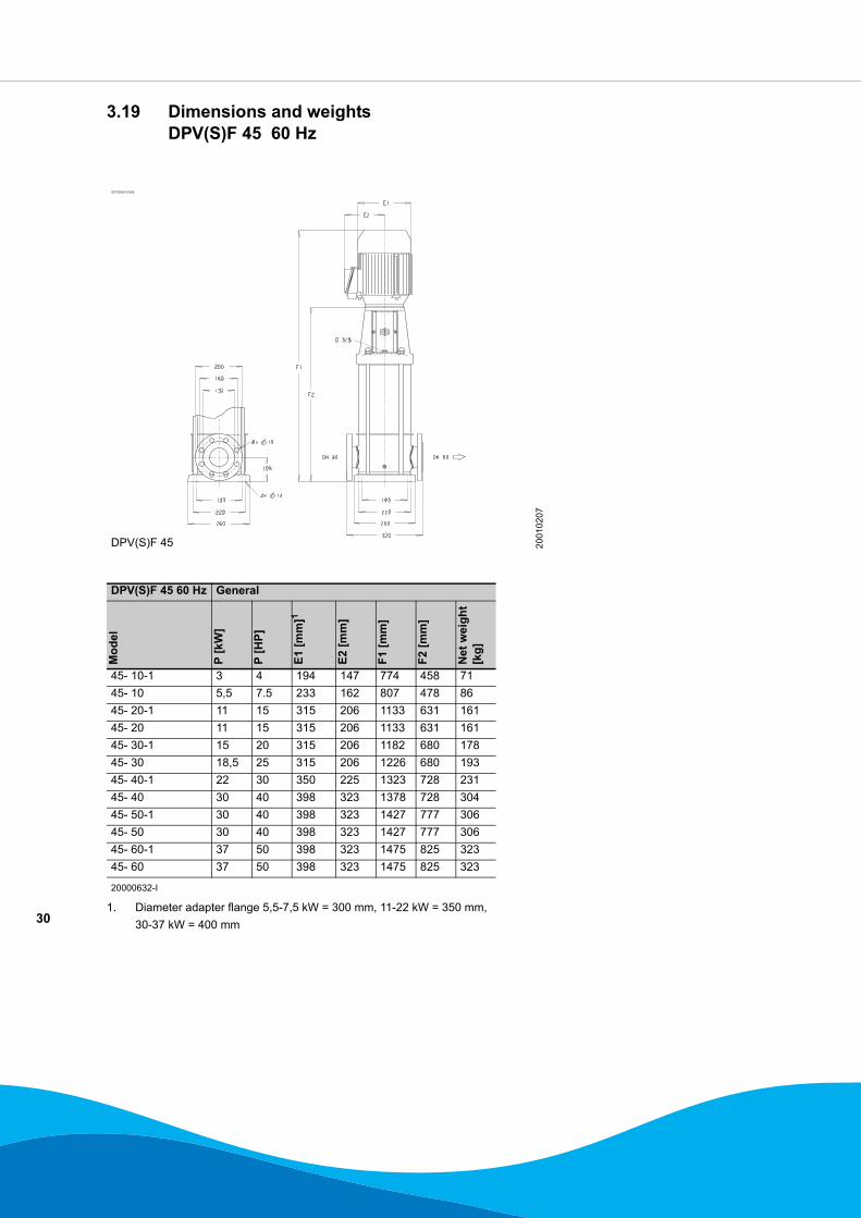
3.19 Dimensions and weights DPV(S)F 45 60 Hz
ID2735/05122005
DPV(S)F 45 2001
0207
DPV(S)F 45 60 Hz General
Mod
el
P [k
W]
P [H
P]
E1 [m
m]1
E2 [m
m]
F1 [m
m]
F2 [m
m]
Net
wei
ght
[kg]
45- 10-1 3 4 194 147 774 458 7145- 10 5,5 7.5 233 162 807 478 8645- 20-1 11 15 315 206 1133 631 16145- 20 11 15 315 206 1133 631 16145- 30-1 15 20 315 206 1182 680 17845- 30 18,5 25 315 206 1226 680 19345- 40-1 22 30 350 225 1323 728 23145- 40 30 40 398 323 1378 728 30445- 50-1 30 40 398 323 1427 777 30645- 50 30 40 398 323 1427 777 30645- 60-1 37 50 398 323 1475 825 32345- 60 37 50 398 323 1475 825 323
20000632-I
1. Diameter adapter flange 5,5-7,5 kW = 300 mm, 11-22 kW = 350 mm, 30-37 kW = 400 mm

31
3.20 Hydraulic performance DPV(S)F 45 60 Hz ≈3500 1/minID 2714/05122005

32
3.21 Dimensions and weights DPV(S)F 65 60 Hz
ID 2761/07062006
DPV(S)F 65 9900
0288
-C
DPV(S)F 65 60 Hz General
Mod
el
P [k
W]
P [H
P]
E1 [m
m]1
E2 [m
m]
F1 [m
m]
F2 [m
m]
Net
wei
ght
[kg]
65- 10 5,5 7.5 233 162 919 590 9365- 20 11 15 315 206 1211 709 16765- 30 15 20 315 206 1300 798 18465- 40 18,5 25 315 206 1433 887 20265- 50 22 30 350 225 1571 976 242
99000287-I
1. Diameter adapter flange 5,5-7,5 kW = 300 mm, 11-22 kW = 350 mm, 30-37 kW = 400 mm

33
3.22 Hydraulic performance DPV(S)F 65 60 Hz ≈3500 1/minID 2716/05122005

34
3.23 Dimensions and weights DPLHS 6 60 Hz
ID 2740/05122005
DPLHS 6 9400
1301
DPLHS 6 60 Hz General
Mod
el
P [k
W]
P [H
P]
E1 [m
m]1
E2 [m
m]
F1 [m
m]
F2 [m
m]
Net
wei
ght
[kg]
6- 80 7,5 10 233 162 896 539 966- 100 11 15 315 206 1131 629 1656- 120 11 15 315 206 1190 688 1686- 140 15 20 315 206 1250 748 185
95000687-F
1. Diameter adapter flange 5,5-7,5 kW = 300 mm, 11-22 kW = 350 mm, 30-37 kW = 400 mm
35
3.24 Hydraulic performance DPLHS 6 60 Hz ≈3500 1/minID 2698/05122005

36
3.25 Dimensions and weights DPVCF 2 60 Hz
ID 2736/05122005
DPVCF 2 2005
0498
DPVCF 2 60 Hz General
Mod
el
P [k
W]
P [H
P]
E1 [m
m]
E2 [m
m]
F1 [m
m]
F2 [m
m]
Net
wei
ght
[kg]
2- 40 0,75 1 150 115 543 309 252- 50 1,1 1.5 150 115 594 330 272- 60 1,1 1.5 150 115 615 351 272- 70 1,5 2 176 136 657 382 312- 80 1,5 2 176 136 678 403 322- 90 1,5 2 176 136 699 424 322- 100 2,2 3 176 136 720 445 362- 110 2,2 3 176 136 741 466 362- 130 2,2 3 176 136 783 508 372- 150 3 4 194 147 876 560 482- 160 3 4 194 147 897 581 482- 180 4 5 233 162 947 623 58
96000823-K

37
3.26 Hydraulic performance DPVCF 2 60 Hz ≈3500 1/minID 2718/05122005

38
3.27 Dimensions and weights DPVCF 4 60 Hz
2737/05122005
DPVCF 4 2005
0499
DPVCF 4 60 Hz General
Mod
el
P [k
W]
P [H
P]
E1 [m
m]1
E2 [m
m]
F1 [m
m]
F2 [m
m]
Net
wei
ght
[kg]
4- 40 1,1 1.5 150 115 573 309 284- 50 1,5 2 176 136 615 340 324- 60 1,5 2 176 136 636 361 324- 70 2,2 3 176 136 657 382 364- 80 2,2 3 176 136 678 403 364- 90 3 4 194 147 750 434 474- 100 3 4 194 147 771 455 474- 110 3 4 194 147 792 476 484- 130 4 5 233 162 842 518 584- 150 4 5 233 162 884 560 594- 160 5,5 7.5 233 162 910 581 60
96000824-M
1. Diameter adapter flange 5,5-7,5 kW = 300 mm, 11-22 kW = 350 mm, 30-37 kW = 400 mm

39
3.28 Hydraulic performance DPVCF 4 60 Hz ≈3500 1/minID 2720/05122005

40
3.29 Dimensions and weights DPVCF 10 60 Hz
ID 2738/05122005
DPVCF 10 2005
0500
DPVCF 10 60 Hz General
Mod
el
P [k
W]
P [H
P]
E1 [m
m]1
E2 [m
m]
F1 [m
m]
F2 [m
m]
Net
wei
ght
[kg]
10- 40 3 4 194 147 712 396 5310- 50 3 4 194 147 739 423 5410- 60 4 5 233 162 774 450 6310- 70 5,5 7.5 233 162 826 497 7010- 80 5,5 7.5 233 162 853 524 7110- 100 7,5 10 233 162 935 578 7610- 120 7,5 10 233 162 989 632 7710- 140 11 15 315 206 1218 716 145
97000795-H
1. Diameter adapter flange 5,5-7,5 kW = 300 mm, 11-22 kW = 350 mm, 30-37 kW = 400 mm

41
3.30 Hydraulic performance DPVCF 10 60 Hz ≈3500 1/minID 2722/05122005

42
3.31 Dimensions and weights DPVCF 18 60 Hz
ID 2739/05122005
DPVCF 18 2005
0501
DPVCF 18 60 Hz General
Mod
el
P [k
W]
P [H
P]
E1 [m
m]1
E2 [m
m]
F1 [m
m]
F2 [m
m]
Net
wei
ght
[kg]
18- 40 7,5 10 233 162 813 456 7718- 50 7,5 10 233 162 847 490 7818- 60 11 15 315 206 1057 555 14518- 70 11 15 315 206 1091 589 14618- 80 15 20 315 206 1126 624 16118- 90 15 20 315 206 1160 658 16218- 100 18,5 25 315 206 1239 693 17718- 120 18,5 25 315 206 1308 762 179
97000797-J
1. Diameter adapter flange 5,5-7,5 kW = 300 mm, 11-22 kW = 350 mm, 30-37 kW = 400 mm

43
3.32 Hydraulic performance DPVCF 18 60 Hz ≈3500 1/minID 2724/05122005

44
3.33 Dimensions and weights DPVCF 32 60 Hz
2919/15052007
DPVCF 32 2007
0258
-A
DPVCF 32 60 Hz General
Mod
el
P [k
W]
P [H
P]
E1 [m
m]1
E2 [m
m]
F1 [m
m]
F2 [m
m]
Net
wei
ght
[kg]
32- 20 7,5 10 233 162 883 526 9732- 30 11 15 315 206 1182 680 16832- 40 15 20 315 206 1230 728 18432- 50 15 20 315 206 1279 777 18732- 60 18,5 25 315 206 1371 825 20432- 70 22 30 350 225 1469 874 24232- 80 30 40 398 323 1572 922 31332- 90 30 40 398 323 1621 971 320
20000601-J
1. Diameter adapter flange 5,5-7,5 kW = 300 mm, 11-22 kW = 350 mm, 30-37 kW = 400 mm

45
3.34 Hydraulic performance DPVCF 32 60 Hz ≈3500 1/minID 2924/26042007

46
3.35 Dimensions and weights DPVCF 45 60 Hz
2920/15052007
DPVCF 45 2007
0259
-A
DPVCF 45 60 Hz General
Mod
el
P [k
W]
P [H
P]
E1 [m
m]1
E2 [m
m]
F1 [m
m]
F2 [m
m]
Net
wei
ght
[kg]
45- 20-1 11 15 315 206 1133 631 16945- 20 11 15 315 206 1133 631 16945- 30-1 15 20 315 206 1182 680 18645- 30 18,5 25 315 206 1226 680 20145- 40-1 22 30 350 225 1323 728 23945- 40 30 40 398 323 1378 728 31245- 50-1 30 40 398 323 1427 777 31445- 50 30 40 398 323 1427 777 31445- 60-1 37 50 398 323 1475 825 33145- 60 37 50 398 323 1475 825 331
20000632-I
1. Diameter adapter flange 5,5-7,5 kW = 300 mm, 11-22 kW = 350 mm, 30-37 kW = 400 mm
47
3.36 Hydraulic performance DPVCF 45 60 Hz ≈3500 1/minID 2923/26042007

48
3.37 Dimensions and weights DPVCF 65 60 Hz
ID 2733/05122005
DPVCF 65 2001
0103
DPVCF 65 60 Hz General
Mod
el
P [k
W]
P [H
P]
E1 [m
m]1
E2 [m
m]
F1 [m
m]
F2 [m
m]
Net
wei
ght
[kg]
65- 10 5,5 7.5 233 162 994 665 9865- 20 11 15 315 206 1286 784 17265- 30 15 20 315 206 1375 873 18965- 40 18,5 25 315 206 1508 962 20765- 50 22 30 350 225 1646 1051 247
99000287-I
1. Diameter adapter flange 5,5-7,5 kW = 300 mm, 11-22 kW = 350 mm, 30-37 kW = 400 mm

49
3.38 Hydraulic performance DPVCF 65 60 Hz ≈3500 1/minID 2726/05122005

50
4 Materials
4.1 Overview of materials
4.2 Materials conversion
Pos. nr. Description DPVE DPV DPVS DPVCF DPLHS101 Pump casing 1.4308 1.4301 1.4404 JL 1040 1.4408108 Stage casing 1.4301 1.4404 1.4301 1.4404160 Cover 1.4301 1.4404 1.4301 1.4404171 Diffuser - 1.4404 1.4301 -10-6 Pump shroud 1.4301 1.4404 1.4301 1.4404210 Shaft 1.4305 1.4401 1.4305 1.4401230 Impeller 1.4301 1.4404 1.4301 1.4404341 Motor stool JL 1040 1.4408412 O-ring EPDM Viton EPDM E425 Viton525 Spacer sleeve 1.4301 1.4401 1.4301 1.4404529 Bearing sleeve - Tungsten-carbide1) Bearing - Ceramic890 Base plate JL 1040 -905 Tie bolt 1.4057920 Nut 1.4301 1.4404 1.4301 1.4404932 Circlip 1.4571
1. The bearing has no pos.nr. because it is a fixed part of the stage casing (108) or diffuser (171)
Material Description Code and material nr. Standard ASTM / AISI1
JL 1040 Cast iron GJL-250 EN 1561 A48:40B1.4301 Chromium-nickel steel X5CrNi18-10 EN 10088 A276:3041.4404 Chromium-nickel-molybdenum steel X2CrNiMo 17-12-2 EN 10088 A276:316L1.4408 Chromium-nickel-molybdenum cast steel GX5CrNiMo 19-11-2 EN 10213 A743CF8M1.4571 Chromium-nickel-molybdenum steel X6CrNiMoTi17-12-2 EN 10088 A276:316Ti1.4057 Chromium-nickel steel X17CrNi16-2--QT800 EN 10088-3 A276:4311.4305 Chromium-nickel steel X8CrNiS 18-9 EN 10088 A276:3031.4401 Chromium-nickel-molybdenum steel X5CrNiMo 17-12-2 EN 10088 A276:3161.4308 Chromium-nickel cast steel GX5CrNi 19-10 EN 10283 A743:CF8
1. Note: The indication of the material designations to ASTM / AISI is not binding

51
4.3 Mechanical seal specifications
Pump series DPVE / DPV(F)(V)
DPVS(F)(V) DPVCF DPVF 24, 32, 45 > 7.5 kW
DPVF 65
DPVSF 24, 32, 45 > 7.5
kWDPVSF 65
DPVCF 32, 45 > 7.5 kWDPVCF 65
DPLHS 6
Mechanical seal type
Max. pressure 1000 kPa 1000 kPa 1000 kPa 1000 kPaDynamic part Carbon Carbon Carbon CarbonStatic part Silicon car-
bideSilicon car-
bideSilicon car-
bideSilicon car-
bideElastomer EPDM Viton EPDM Viton
Max. pressure 2500 kPa 2500 kPa 2500 kPa 2500 kPa 2500 kPa 2500 kPaDynamic part Silicon car-
bideSilicon car-
bideTungsten car-
bideSilicon car-
bideSilicon car-
bideTungsten car-
bideStatic part Carbon Carbon Carbon Carbon Carbon CarbonElastomer EPDM Viton EPDM E425 EPDM Viton EPDM E425
Max. pressure 4000 kPaDynamic part CarbonStatic part Tungsten car-
bideElastomer Viton
52
5 Connections
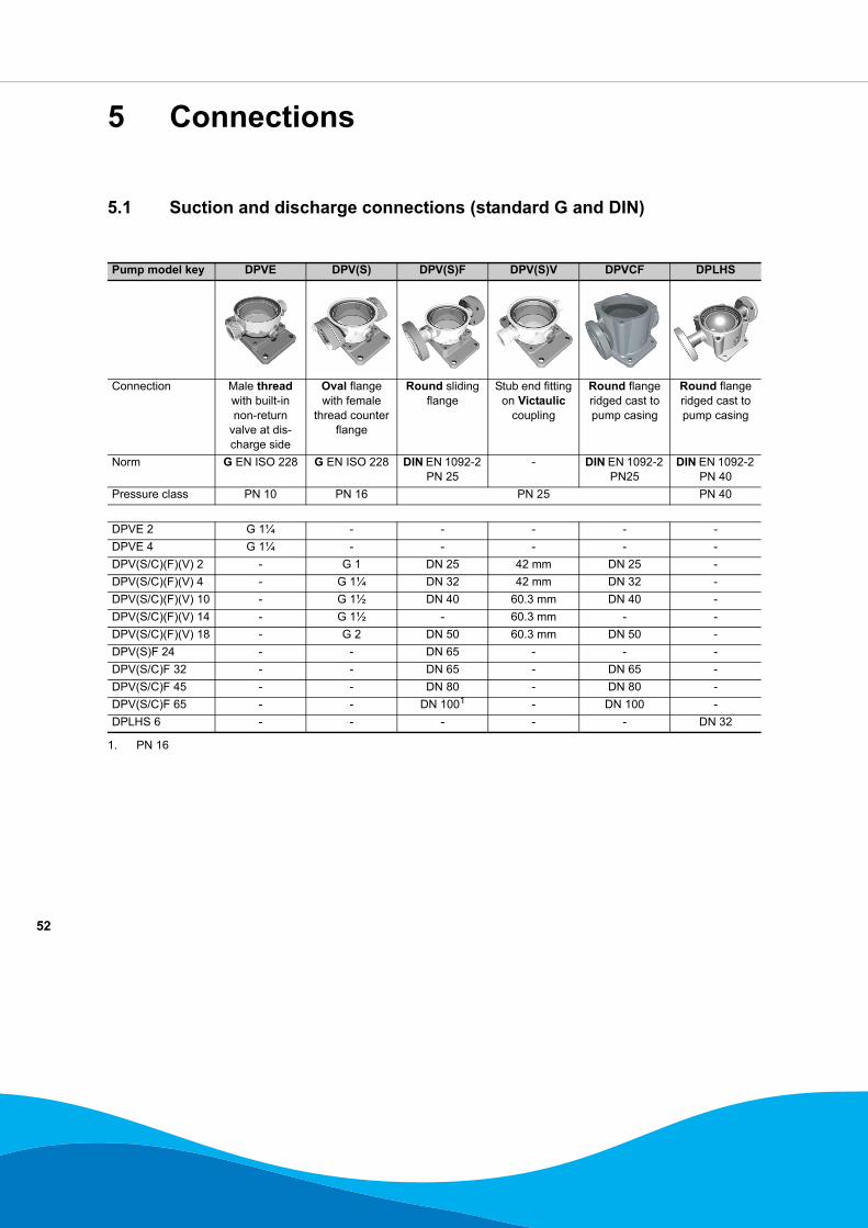
5.1 Suction and discharge connections (standard G and DIN)
Pump model key DPVE DPV(S) DPV(S)F DPV(S)V DPVCF DPLHS
Connection Male thread with built-in non-return
valve at dis-charge side
Oval flange with female
thread counter flange
Round sliding flange
Stub end fitting on Victaulic
coupling
Round flange ridged cast to pump casing
Round flange ridged cast to pump casing
Norm G EN ISO 228 G EN ISO 228 DIN EN 1092-2 PN 25
- DIN EN 1092-2 PN25
DIN EN 1092-2 PN 40
Pressure class PN 10 PN 16 PN 25 PN 40
DPVE 2 G 1¼ - - - - -DPVE 4 G 1¼ - - - - -DPV(S/C)(F)(V) 2 - G 1 DN 25 42 mm DN 25 -DPV(S/C)(F)(V) 4 - G 1¼ DN 32 42 mm DN 32 -DPV(S/C)(F)(V) 10 - G 1½ DN 40 60.3 mm DN 40 -DPV(S/C)(F)(V) 14 - G 1½ - 60.3 mm - -DPV(S/C)(F)(V) 18 - G 2 DN 50 60.3 mm DN 50 -DPV(S)F 24 - - DN 65 - - -DPV(S/C)F 32 - - DN 65 - DN 65 -DPV(S/C)F 45 - - DN 80 - DN 80 -DPV(S/C)F 65 - - DN 1001 - DN 100 -DPLHS 6 - - - - - DN 32
1. PN 16

53
5.2 Suction and discharge connections (optional ASME)
Pump model key DPV(S)F DPLHS
Connection Round sliding flange
Round flange ridged cast to pump casing
Norm ASME B 16.1 cl.250
ASME B 16.5 cl.600
Pressure class PN40
DPV(S)(F)(V) 2 1¼” -DPV(S)(F)(V) 4 1¼” -DPV(S)(F)(V) 10 2” -DPV(S)(F)(V) 14 - -DPV(S)(F)(V) 18 2” -DPV(S)F 24 - -DPV(S)F 32 2½” -DPV(S)F 45 3” -DPV(S)F 65 4”1 -DPLHS 6 - 1¼”
1. class 125

54
5.3 Suction and discharge connections (optional Rc and JIS)
Pump model key DPV(S) DPV(S)F
Connection Oval flange with female
thread counter flange
Round sliding flange
Norm Rc EN 10226 JIS B2238Pressure class PN 16 16 K
DPV(S)(F)(V) 2 Rc 1 JIS 25DPV(S)(F)(V) 4 Rc 1¼ JIS 32DPV(S)(F)(V) 10 Rc 1½ JIS 40DPV(S)(F)(V) 14 Rc 1½ -DPV(S)(F)(V) 18 Rc 2 JIS 50DPV(S)F 24 - JIS 65DPV(S)F 32 - JIS 65DPV(S)F 45 - JIS 80DPV(S)F 65 - JIS 100

55
6 Factory options
6.1 Factory options
Description: Applicable model: Standard: OptionsSealing:Sleeve and stage O-rings: DPV EPDM Viton
DPVS Viton HNBRE425 EPDMEPDM
Mechanical seal: DPV Ca/Sic/EPDM Sic/Ca/EPDMDPVS Sic/Ca Sic/Sic/EPDMDPVCF Tuc/Tuc Sic/Ca/Viton
Sic/Sic/VitonTuc/Tuc/VitonTuc/Tuc/HNBRSic/Sic/KalrezSic/Ca/Kalrez
Mechanical:Vent and drain plugs AISI 316 DPV Vent and drain plugs brass Vent and drain plugs AISI 316Safety vent plug AISI 316 All Standard vent plug Safety vent plug AISI 316Non-return valve DPVE With pre-assembled NRV No pre-assembled NRVColor finish All Pump and motor RAL 5001 RAL 3000 (fire red)De-staging All Intermediate impeller stage Stage without impellerDIN flanges DPV Oval flange PN 16 Round flange DIN PN 25JIS flanges DPVF Round flange DIN PN 25 Round flange JIS PN 25ASME flanges DPVF Round flange DIN PN 25 Round flange ASME
B 16.1 cl. 250Motor:High efficiency motor 3 phase 2-pole 0,37 kW - 37 kW Eff class 2 Eff class 1Anti condensation heater 3 phase 0,37 kW - 37 kW None With anti condensation heater
1~230 VRain cover 3 phase 0,37 kW - 37 kW None Rain cover on fan hoodPTC thermistors 3 phase 0,37 kW - 37 kW None With 3 PTC thermistorsHarting stecker 3 phase 0,37 kW - 37 kW None Cable connection provided
with 10-pole Harting steckerConnection box position 0,37 kW - 37 kW 9h 0h, 3h, 6hIncreased motor power 0,37 kW - 37 kW Standard motor power One step higher motor powerEnlarged motor latern 0,37 kW - 37 kW Standard motor latern Motor latern to fit one step
higher motorpowerWinding configuration 3 phase 0,37 kW - 2 kW 230 / 400 V 400 / 692 V
3 phase 3 kW - 37 kW 400 / 692 V 230 / 400 VWinding tension 3 phase 0,37 kW - 37 kW 400 V Y or Δ 500 V Y or Δ

56
7 Accessories
7.1 Horizontal mounting kit
In special applications it could be a solution to mount the pump in a horizontal position. Although the pump is designed for vertical positioning the hydraulic parts of the pump are also capable of functioning in a horizontal position. This option is limited by the motor rating. The motors of 11kW and above are equipped with a co-axial bearing which is not suitable for horizontal positioning.
To ensure a proper and stable horizontal mounting position for the pump, stainless steel AISI 304 support frames are available. To mount the support frames, bolts up to a maximum of M12 can be used.
The horizontal mounting kit includes the following parts:
• Pump bracket support• Motor flange support• 4 bolts M12• 4 washers 12mm• 4 nuts M12
7.1.1 Dimensions of pumps fitted with horizontal mounting kit
Dimensions are related to the dimensions of the complete pump in standard vertical position and are mentioned in [mm].
ID2628/30052005
Motor flange support 2005
0451
-F
ID2627/30052005
Pump bracket support 2005
0451
-F
DPV(S)(V) 2/4 D = 82DPV(S)(C)(F) 2/4 D = 107Motor [kW] Art. nr. C H A B Weight
[kg]0.37 1.1 18707001 F2+47 120 100 100 1.701.5 2.2 187070043 4 18707002 F2+395.5 7.5 18707003 F2-17 170 210 2.60
20050451-F
DPV(S)(V) 10/18DPV(S)(C)F 10
D = 112
DPV(S)(C)F 18 D = 122Motor [kW] Art. nr. C H A B Weight
[kg]0.55 1.1 18707011 F2+47 140 130 130 2.501.5 2.2 187070143 4 18707012 F2+39 2.405.5 7.5 18707013 F2-17 170 210 2.90
20050451-F

57
7.2 Thrust bearing housing
The standard DP-Pumps motors are specially designed to drive the pump. When a standard IEC or NEMA norm motor has to be installed (or a special motor to fulfill the applications requirement, like explosion proof, high efficiency) a special bearing housing must be installed to relieve the motor of the axial force created by the pump.
ATTENTIONThis option is not applicable for pump model DPVE.
ATTENTIONOnly a motor with a standard key can be installed with a thrust bearing housing.
ATTENTIONThere is no need to change the motor stool of the pump. The bearing flange can be mounted on the standard motor stool of the pump.
7.2.1 Dimensions and weights.
The total height increase of the pump will be 113,5 mm / 4.47 inch. The weight of the thrust bearing housing kits are given in the table below:
Table 4: weight of the thrust bearing housings kits
DPV(S)(V)(F) 14 D = 112Motor [kW] Art. nr. C H A B Weight
[kg]0.55 0.75 18707021 F2+47 140 130 130 2.501.1 1.5 187070232.2 4 18707022 F2+39 2.40
20050451-F
DPV(S)(F) 24 D = 137Motor [kW] Art. nr. C H A B Weight
[kg]1.1 1.5 18707031 F2+47 170 210 180 4.002.2 4 18707032 F2+395.5 7.5 18707033 F2-17 3.90
20050451-F
DPV(S)(C)F 32/45 D = 137DPV(S)(C)F 65 D = 172Motor [kW] Art. nr. C H A B Weight
[kg]1.5 2.2 18707041 F2+47 170 210 180 4.003 4 18707042 F2+395.5 7.5 18707043 F2-17 3.90
20050451-F
ID2641/11072005
Thrust bearing housing 2005
0227
-B
Frame size
Motor-shaft
Kit art. nr. Weight[kg]
Weight [lbs]
132 38 18708020 7,97 17.57160 42 18708021 8,25 18.19180 48 18708022 9,30 20.50200 55 18708023 9,44 20.81

58
8 Sectional drawings
8.1 Parts list
Number (ZN) Description:101 Pump casing108 Stage casing160 Cover171 Diffuser210 Shaft230 Impeller341 Motor stool400 Gasket411 Joint ring412 O-ring433 Mechanical seal471 Seal cover500 Ring509 Intermediate ring525 Spacer sleeve525.08 Spacer sleeve529 Bearing sleeve554 Washer560 Pin681 Coupling guard722 Taper piece, flanged723 Flange742 Non-return valve800 Motor801 Flanged motor802 Motor for close coupling831 Fan impeller832 Fan hood833 Terminal box835 Terminal board837 Condenser862 Coupling shell890 Baseplate fabricated or cast900 Screw901 Hexagon head bolt903 Screwed plug904 Grub screw905 Tie bolt913 Vent plug914 Hexagon socket head cap scr.920 Nut930 Safety device932 Circlip10-6 Pump shroud81-37 Terminal box coverplate

59
8.2 Sectional drawing DPVE 2/4
ID 2692/05122005
2003
0219
-D

60
8.3 Sectional drawing DPV(S) 2/4/10/14/18
ID 2696/05122005
9500
0589
-I

61
8.4 Sectional drawing DPV(S)F 24/32
ID 2688/05122005
2001
0712
-F

62
8.5 Sectional drawing DPV(S)F 24/32 with cartridge seal
ID 2689/05122005
2001
0713
-F

63
8.6 Sectional drawing DPV(S)F 45
ID 2690/05122005
2001
0714
-F

64
8.7 Sectional drawing DPV(S)F 45 with cartridge seal
ID 2691/05122005
2001
0715
-F

65
8.8 Sectional drawing DPV(S)F 65
ID 2687/05122005
2000
0052
-G
66
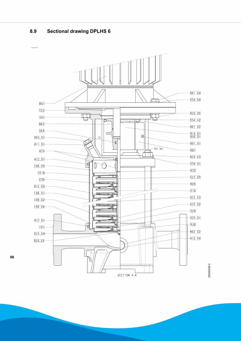
8.9 Sectional drawing DPLHS 6
ID 2693/05122005
2003
0238
-C

67
8.10 Sectional drawing DPVCF 2/4/10/18
ID 2694/07062006
2004
0174
-C
800
341
920.01
914.01
862
560
412.02 160
412.01
10-6
108.05
108.04
412.03
108.02
108.01
101
914.03
411.02
554.02
901.02
681
901.01
554.01
210
913
411.01
920.03
433
932
905
525.05
230
525.01
529
525.03
525.04
930
920.02

68
8.11 Sectional drawing DPVCF 32
ID 2926/15052007
2007
0217
-A

69
8.12 Sectional drawing DPVCF 32 with cartridge seal
ID 2927/15052007
2007
0218
-A

70
8.13 Sectional drawing DPVCF 45
ID 2928/15052007
2007
0219
-A

71
8.14 Sectional drawing DPVCF 45 with cartridge seal
ID 2929/15052007
2007
0220
-A

72
8.15 Sectional drawing DPVCF 65
ID 2695/07062006
2004
0437
-C

73

74

75

dp pumps
dp pumpsP.O. Box 282400 AA Alphen aan den RijnThe Netherlands
t +31 172 48 83 25f +31 172 46 89 30
02-2008
97004435
Subject to modifications without prior notice
Top Related