


Languages
Pages
Legal


T630 Treadmill Repair Manual
SPORTS ART INDUSTRIAL CO., LTD.

【Table of Contents】
1. Unit Components
1-1-1. T630 Product Picture 1-1-2. T630 Treadmill Components – (1) Display Area 1-1-3. T630 Treadmill Components – (2) Motor Area 1-1-4. T630 Display Components – (3) Display Board Front 1-1-6. T630 Display Components – Display Board Back 1-1-7. T630 Drive Board Components 1-1-8. T630 Display Components – Other 1-1-9. T630 Display Components – Other
2. Introduction
2-1-1. T630 Specifications 2-1-2. Introduction to the T630 Display
2-1-3. Display Indicators 2-1-4. Display Keys
3. Operation 3-1-1. T630 Operation – Start Up, Speed Key 3-1-2. Incline Key, Stop Key, Change Key 3-1-3. Clear Key, Program Key 3-1-4. Basic Settings: MPH/KPH; Basic Settings: Distance
0-0-1

【Table of Contents】
4. Block Diagrams
4-1-1. Display Board Cable Connections 4-2-1. Drive Board Cable Connections
5. Cable Connections 5-1. Display Board 5-1-1. T630 Display Board Cable Connections 5-1-2. T630 Display Board Components 5-1-3. T630 Display Board LED Indicators
5-1-4. T630 Display Board Cable Connections 5-2. Drive Board
5-2-1 T630 Drive Board Cable Connections 5-2-2. T630 Drive Board Components 5-2-3. T630 Drive Board LED Indicators 5-2-4. T630 Drive Board LED Indicators 5-2-5. T630 Drive Board Cable Connections 5-2-6. T630 Drive Board Jumper Placement
0-0-2

【Table of Contents】
6. Error Messages
6-1-1. ERR1-Motor Does Not Rotate (Continued through 6-1-3) 6-2-1. ERR1-Motor Does Rotate (Continued through 6-2-3) 6-3-1. ERR3 (Continued through 6-3-3) 6-4-1. ERR7 (Continued through 6-4-3) 6-5-1. Display Key Malfunction (Continued through 6-5-2) 6-6-1. Unit Does Not Turn On (Continued through 6-6-3) 6-7-1. No Telemetry Heart Rate (Continued through 6-7-3) 6-8-1. Incline Does Not Operate Up or Down (Continued through 6-6-2) 6-9-1. Main Fuse Broke (Continued through 6-9-2) 6-10-1.Service Required (Continued through 6-10-2) 6-11-1.Heart Touch Rate Malfunction (Continued through 6-11-3)
7. Electronic Component Testing
7-1-1. EMI Filter Test 7-2-1. Motor Test 7-3-1. Transformer Test at the Drive Board 7-4-1. Inductor Test (220V units only) 7-5-1. Motor Voltage Test at the Drive Board 7-6-1. Drive Board IGBT Test 7-7-1. Drive Board VCC Test
0-0-3
【Table of Contents】
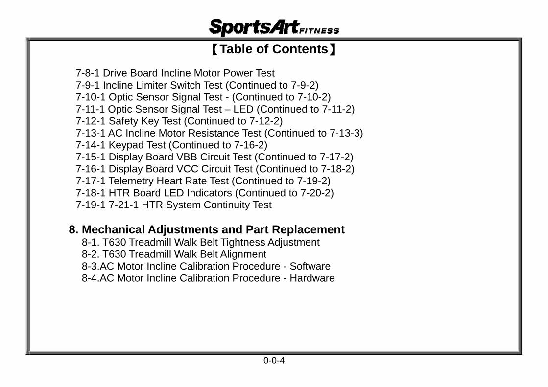
7-8-1 Drive Board Incline Motor Power Test 7-9-1 Incline Limiter Switch Test (Continued to 7-9-2) 7-10-1 Optic Sensor Signal Test - (Continued to 7-10-2) 7-11-1 Optic Sensor Signal Test – LED (Continued to 7-11-2) 7-12-1 Safety Key Test (Continued to 7-12-2) 7-13-1 AC Incline Motor Resistance Test (Continued to 7-13-3) 7-14-1 Keypad Test (Continued to 7-16-2) 7-15-1 Display Board VBB Circuit Test (Continued to 7-17-2) 7-16-1 Display Board VCC Circuit Test (Continued to 7-18-2) 7-17-1 Telemetry Heart Rate Test (Continued to 7-19-2) 7-18-1 HTR Board LED Indicators (Continued to 7-20-2) 7-19-1 7-21-1 HTR System Continuity Test
8. Mechanical Adjustments and Part Replacement 8-1. T630 Treadmill Walk Belt Tightness Adjustment 8-2. T630 Treadmill Walk Belt Alignment 8-3.AC Motor Incline Calibration Procedure - Software 8-4.AC Motor Incline Calibration Procedure - Hardware
0-0-4

1.T630 Product Picture
1-1-1

2.T630 Treadmill Components-(1) Display Area
Display
Key Pad HTR Handlebar (right)HTR Handlebar (left)
1-1-2

3.T630 Treadmill Components-(2) Motor Area
1-1-3
EMI Filter
Motor
Optic Sensor
Calibration Switch
Optic Wheel
Drive Board
Incline Motor Transformer
Motor Thermal Sensor
Inductor

4. T630 Display
1-1-4

5.T630 Display Components – Display Board Front
1-1-5

6.T630 Display Components – Display Board Back
1-1-6

7. T630 Drive Board Components
1-1-7

8.T630 Display Components – Other
Part Key Pad Keys Part Optic Sensor
Part HRC Board
1-1-8

9.T630 Display Components - Other
Part HTR Boad Part EMI Filter
1-1-9

T630 Specifications
Specification Notes Details Power S Exter oupply i r Power Supply 110V (USA);
220V (Eu
rope)
Main WinHRC hea
Cdow Display Rate, rt rate window: 65%, 80%, Heart alories, Speed, Time, Distance,
Cal/hr, Mets, Pace, Incline
Seconda Dot Matriry Window Display
x 15 X 8 Window
Speed R 0.2 - 20.00.1 – 12.
ange KPH
0MPH
Incline R 0 % to 15 AC MotoProgram/ange % r
Control
Heart RaHTR Hea
eleste Detection Wirrt Touch Rate (contact pads)
s
Telemetry Heart Rate (HR Transmitter)
KPH/MP Program
H Setting
OperatioManual,HTEST,WTn
ill,Random,Interval,Track,FIT Loss,Zone Trainer,FAT BURN,
Glute ,
2-1-1

T630 Introductions- Display Board
1. Display Window Introduction
65% Heart Rate Target Shows 65% Heart Rate Target
80% Heart Rate Target Shows 80% Heart
Rate Target
Dot Matrix Workout
Illustrations
1. This LED flashes when heart rate is detected.
HEART RATE Window Shows Actual Heart Rate
Information Window
Workout Feedback
2-1-2

T630 Introductions- Display Indicators
Distance & Incline Window Distance lit = shows
distance Incline lit = shows incline
position
Speed & Mets Speed lit = shows speed Mets lit = shows METS value
Time & Pace Window Time lit = Exercise time Pace lit = Pace value
Exercise Program Area Lit = shows exercise
programs: Manual, Hill, Random,Interval,Trcak, FIT test, WT Loss,Zone Trainer,FAT Burn,Glute
Calories & Cal/HR Window Calories lit = shows calories
expenditure Cal/HR lit = shows Cal/HR
value
2-1-3

T630 Introductions - Display Keys
<CHANGE> Key Press to change
feedback information.
INCLINE<>/<> Key Press to set incline position.
SPEED<>/<> Key Press to set unit speed.
<MANUAL><HILL><RANDOM>< INTV > <Track> <FIT Test><WT LOSS> <ZONE TRAINER> <FAT Burn><GLUTE >Keys
Press to choose an exercise program.
<QUICK START>Key Press to start without inputting user information.
<START> <QUICK START> <ENTER> Key Press Start to start. Press Quick Start to start without
entering user information. Press ENTER to confirm your choice.
<1>~<9> and <CLEAR> Keys
Press to directly set numerical values or to clear settings. It replaces the keys.
<STOP>Key Press to stop operation.
2-1-4

T630 Operation
1. Start Up Function: Press the Quick Start key to start operating the unit. Operation: (1) The display shows “SPORTSART – T630”. After two seconds, “SELECT PROGRAM OR QUICKSTART” scrolls across the display.
Press the QUICK START key to start operating or press the PROGRAM key to operatean exercise program.
(2) The PROGRAM LED flashes After pressing a program key, the associated program indicator lights up. The setting window shows two seconds. If you press the <RANDOM> key, the RANDOM LED lights. “RANDOM” appears.
(3) User age and weight setting When “AGE – 35”appears, press the numerical keys or INCLINE/. Then press the <ENTER> key to confirm your setting. When “WEIGHT -- 75 KG” appears, press the numerical keys or INCLINE/. Then press the <ENTER> key to confirm your setting. (4) After entering such information, you can start operating the treadmill.
2.SPEED Key Function: Set speed function Operation: (1) Press the SPEED <> key. Values in the speed window increase. Speed increases.
(2) Press the SPEED <> key. Values in the speed window decrease. Speed decreases.(3) SPEED range: 0.2~20 KPH (0.1~12 MPH).
3-1-1

3.INCLINE Key Function Function: Set treadmill incline position. Operation: (1) Press the INCLINE<> key. Values in the incline window increase. Incline operates up.
(2) Press the INCLINE<> key. Values in the incline window decrease. Incline operates down. (3)INCLINE range: 0~15%; increments of 0﹒5%.
4.STOP Key Function Function: Leave an exercise program. Operation: (1) In QUICKSTART mode, press the<STOP> key to leave the exercise program.
(2) If in the START mode, having entered user information, press the<STOP> key to stop exercising. Feedback pauses as is.
(3) In any mode, hold the<STOP> key three seconds to leave the present mode and return to start up screen.
5.CHANGE Key Function Function: Change the display feedback row.
Operation: (1) Press the <Change Display> key while exercising to toggle from one feedback row to another feedback row. Corresponding LEDs light. Top row: CALORIES、SPEED、TIME、DISTANCE. Bottom row: CAL/HR、METS、PACE、INCLINE.
(2) In SCAN mode, the SCAN LED lights. Every four seconds, the display toggles from one feedback row to the other row. If you press the SCAN key again, the
scan LED extinguishes. The display continues to show the activated feedback row.
3-1-2

6.CLEAR Key
Function: Clear entered values to 0. Operation: Press to clear entered values to 0.
7.PROGRAM Key
Function: Select exercise programs. Operation: (1) Press any PROGRAM key. Its corresponding LED lights.
(2) Programs include MANUAL、HILL、RANDOM、INTV、TRACK、FAT TEST、Wt LOSS、ZONE TRAINER、FAT BURN、GLUTE
3-1-3

9. Basic Settings
Function: (1) Set KPH/MPH, total distance, and total time. Operation: (1) Hold the <Change Display> key for three seconds to enter the basic setting mode. Message window shows the current setting as either
“UNIT - MPH” or “UNIT - KPH”. Press the INCLINE</>key to change your setting.
(2) Press the <ENTER> key to see the total distance: “DIST-XXXXX KM”.
(3) Press the <ENTER> key to see the total time: “TIME-XXXXX HOUR”.
(4) Press the <ENTER> key to see the display main program IC version, for example, “CTL T630_1X”. (5 Press the <ENTER> key to see the drive board main program IC version, for example,
“DRV T630_1X”. Press the <ENTER> key to return to the startup screen. Or press the <STOP> key to exit the basic setting mode.
3-1-4

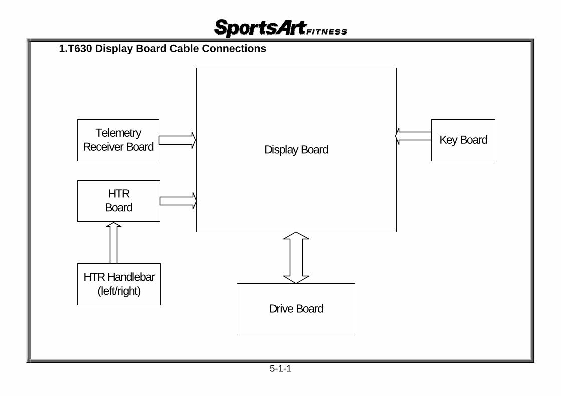
1.T630 Display Board Cable Connections
Display Board
HTRBoard
Key BoardTelemetry Receiver Board
HTR Handlebar (left/right)
Drive Board
4-1-1

2.T630 Drive Board Cable Connections
Display Board
Drive Board
Calibration Switch
Incline Motor
MotorOptic
Sensor
Inductor
FUS
E
EMI Filter
On/Off Switch
Thermal Sensor
Transformer
Power Cord
4-1-2
1.T630 Display Board Cable Connections
Display Board
HTRBoard
Key BoardTelemetry Receiver Board
HTR Handlebar (left/right)
Drive Board
5-1-1

2.T630 Display Board Components
5-1-2

3.T630 Display Board LED Indicators
POWER1 Indicator Lit indicates 5 VDC
power supply
5-1-3

4.T630 Display Board Cable Connectors
CON3 To heart rate board
CON2 To EMG STOP
CON4 To telemetry receiver board
CON1 to drive board
CON5 To key board
5-1-4

1.T630 Drive Board Cable Connections
Display Board
Drive Board
Calibration Switch
Incline Motor
MotorOptic
Sensor
Inductor
FUS
E
EMI Filter
On/Off Switch
Thermal Sensor
Transformer
Power Cord
5-2-1

2. T630 Drive Board Components
5-2-2

3. T630 Drive Board LED Indicators
LED1 SOFT Indicator Two seconds after start up, this LED lights
LED10 Motor Overheat Shutoff Indicator Lit indicates motor overheat shutoff is activated
LED2 POWER Indicator Lit indicates power supply
LED5 EMG Indicator Lit indicates drive board is supplying power to motor. Not lit indicates emergency off function is activated.
LED9 UP Indicator Lit indicates incline is operating up.
LED7 DN Indicator Lit indicates incline is operating down.
5-2-3

4.T630 Drive Board LED Indicators
LED6 MC Indicator Flashing indicates motor is moving.
LED8 ZERO Indicator Lit indicates incline is calibrated.
LED11 I_SENSE LED Lit indicates start up current restriction is activated.
5-2-4

5. T630 Drive Board Cable Connections
CON7 To incline calibration switch
M+, M- To motor
CON8 To motor thermal sensor
CON2, CON3 To display board
CON5 To optic sensor
L1, L2 To inductor
CON6 To incline motor
CON1 To transformer
AC1, AC2 To power cord
5-2-5

6. T630 Drive Board Jumper Placement
2
1
3
JP3 1. Using the jumper to make electrical continuity across pin 1 & 2 makes the incline operate up. 2. Using the jumper to make electrical continuity across pin 2 & 3 makes the incline operate down.
5-2-6

T630 Error Message: ERR 1-Motor Does Not Rotate 1. Definition: (1) Motor doesn’t rotate. Display board CPU does not read the optic
sensor signal.
2. Block Diagram
Display Board
Drive Board
Motor2 pin
Motor Voltage
Motor Speed Signal
Inductor(220V only)
Transformer
TransformerVoltage
13 P
IN Optic
Sensor Signal
LED6_MC
6-1-1

3. Operation
Order Part Troubleshooting
1 Display Board
1. Display CPU ends out the motor control signal to the drive board to control motor speed.
s
2. If the CPU does not receive the motor speed CLOCK signal, the display shows ERR1.
2 13-PIN Data Cable
1. The SPEED signal travels from the display to the drive board via the data cable. s2. The CLOCK ignal travels from the drive board to the display board via the data
cable.
3 Drive Board 2
1. After processing the motor signal, the drive board emits voltage to the motor, making the motor rotate.
. The drive board sends the CLOCK signal to the display board.
4 Motor 1. According to voltage supply from the drive board, the motor rotates, rotating the walk belt.
5 Inductor (220V)
1. Inductor is used only on 220V models. v2. Inductor processes AC oltage from the drive board into VH voltage for the drive
board drive circuit. 6 Transformer 1. The transformer supplies power for all drive board circuits.
4. Circumstance of Malfunction
(1). Press SPEED<> or <>. The walk belt does not rotate. The display shows “ERR1”. 5. Troubleshooting
Order Part Troubleshooting
1 D 123
isplay Board
. Inspect the display CON1 cable connections.
. Inspect the display board U6 connection. Replace as a test.
. Replace the display board as a test. 6-1-2

Order TPart roubleshooting
2 t13-PIN Data 1. Inspect Cable he data cable and its connections.
3 Drive Board
se s2. Inspect d
C w
4. Replace
3. Inspect3. Inspect
1. Plea ee basic testing on pages 7-4, 7-5, 7-6. rive board CN2, CN3 connections. N1 or L1, L2 connections. hether the drive board EMG indicator is lit. the drive board as a test.
4 tor
1. Please r2. Inspect m
for vect t
4. Replace
Mo
efer to basic testing on page 7-2. otor M+, M- connections.
3. Test3. Insp
oltage at motor M+, M- terminals. he motor brushes for wear. the motor as a test.
5 Tra orme
1. Please s1. Inspect t
t3. Replace
nsf r 2. Test the
ee basic testing on page 7-4. he transformer wires and their connections. ransformer secondary wires for voltage. the transformer as a test.
6 Induc (21. The indu
tor 20V) 2. Inspect t3. Replace
ctor is used only on 220V models. he inductor wire connections. the inductor as a test.
6-1-3
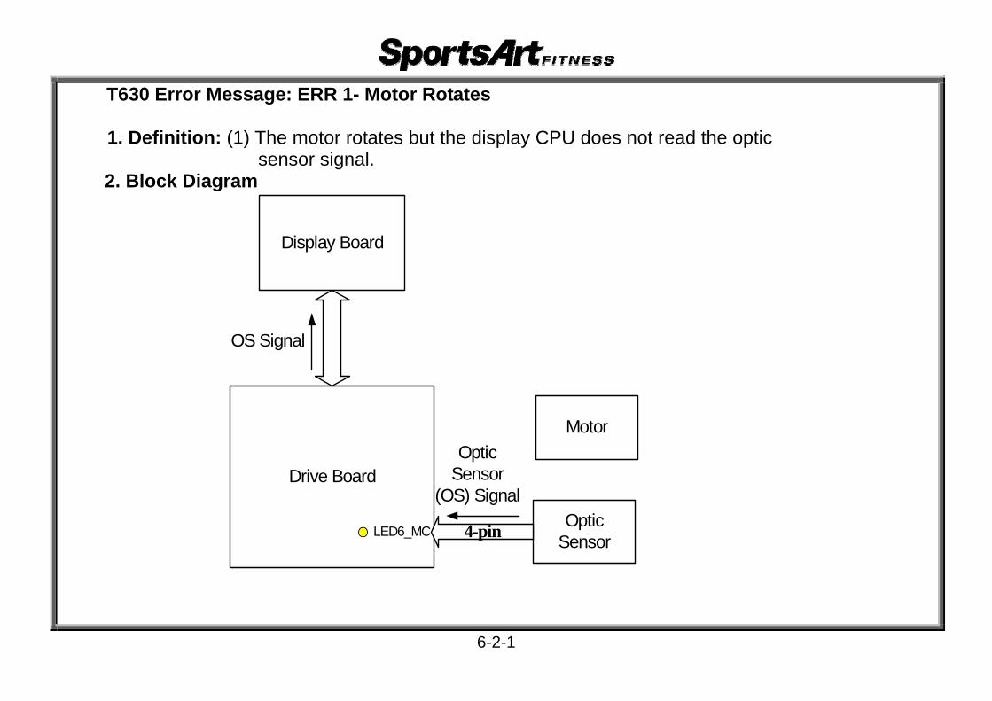
T630 Error Message: ERR 1- Motor Rotates 1. Definition: (1) The motor rotates but the display CPU does not read the optic
sensor signal. 2. Block Diagram
Display Board
Drive Board
Motor
OS Signal
LED6_MCOptic
Sensor4-pin
Optic Sensor
(OS) Signal
6-2-1

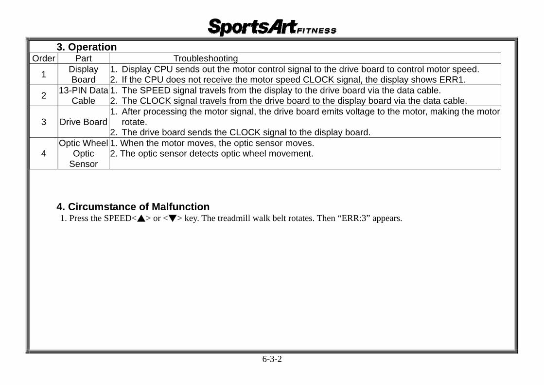
3. Operation
Order Part Troubleshooting
1 Display Board
1. Display CPU sends out the motor control signal to the drive board to control motor speed.
2. If the CPU does not receive the motor speed CLOCK signal, the display shows ERR1.
2 13-PIN Data Cable
1. The SPEED signal travels from the display to the drive board via the data cable. 2. The CLOCK signal travels from the drive board to the display board via the data
cable.
3 Drive Board 2
1. After processing the motor signal, the drive board emits voltage to the motor, making the motor rotate.
. The drive board sends the CLOCK signal to the display board.
4 Motor 1. According to voltage supply from the drive board, the motor rotates, rotating the walk belt.
5 Inductor (220V)
1. Inductor is used only on 220V models. 2. Inductor processes AC voltage from the drive board into VH voltage for the drive
board drive circuit. 6 Transformer 1. The transformer supplies power for all drive board circuits.
4. Circumstance of Malfunction
(1). Press SPEED<> or <>. The walk belt does not rotate. The display shows “ERR1”. 5. Troubleshooting
Order Part Troubleshooting
1 D 123
isplay Board
. Inspect the display CON1 cable connections.
. Inspect the display board U6 connection. Replace as a test.
. Replace the display board as a test. 6-2-2

Order TPart roubleshooting
2 th13-PIN Data 1. Inspect Cable e data cable and its connections.
3 Drive Board
se s2. Inspect d
Cw
4. Replace
3. Inspect 3. Inspect
1. Plea ee basic testing on pages 7-4, 7-5, 7-6. rive board CN2, CN3 connections. N1 or L1, L2 connections. hether the drive board EMG indicator is lit. the drive board as a test.
4 M or
1. Please re2. Inspect m
for vect th
4. Replace t
ot
fer to basic testing on page 7-2. otor M+, M- connections.
3. Test 3. Insp
oltage at motor M+, M- terminals. e motor brushes for wear. he motor as a test.
5 Optic ens
1. Inspect th2. Inspect
oe t
S or optic sens3. Replac
e optic sensor wires and their connections. whether the MC indictor on the drive board flashes as the r wheel rotates. he optic sensor as a test.
6-2-3

T630 Error Message: ERR 3 1. Definition: Display SPEED setting and actual speed differ.
2. Block Diagram
Display Board
Drive Board
Motor
Optic
Sensor Signal
LED6_MCOptic
Sensor4 pin
Optic Sensor Signal
Motor Speed Signal
Optic Wheel
6-3-1
3. Operation
Order Part Troubleshooting
1 D 12 isplay
Board . Display CPU sends out the motor control signal to the drive board to control motor speed. . If the CPU does not receive the motor speed CLOCK signal, the display shows ERR1.
2 1 3-PIN Data Cable
12
. The SPEED signal travels from the display to the drive board via the data cable.
. The CLOCK signal travels from the drive board to the display board via the data cable.
3 D1
rive Board2
. After processing the motor signal, the drive board emits voltage to the motor, making the motor rotate.
. The drive board sends the CLOCK signal to the display board.
4O
S
ptic WheelO
12.ptic
ensor
. When the motor moves, the optic sensor moves. The optic sensor detects optic wheel movement.
4. Circumstance of Malfunction 1. Press the SPEED<> or <> key. The treadmill walk belt rotates. Then “ERR:3” appears.
6-3-2

5. Troubleshooting
Order TroublPart eshooting
1 Disp Bopect t
Ut
lay ard 2. Inspect 3.Replace
1. Ins he display board CON1 cable connection. 6 IC on the drive board. he display as a test.
2 13-PIN Dat ta 1. Inspect Cable he data cable and its connections.
3 Drive Boardse s
de
2. Inspect3. Replac
1. Plea ee basic testing on pages 7-6. rive board CN5 connections. the drive board as a test.
4 tor 1. Please rlace Mo efer to basic testing on page 7-2.
2. Rep the motor as a test.
5 Opti Whee wc l 1. Inspect hether the optic wheel has all of its teeth.
6 Optic ens
1. Inspect w2. Inspect
e3. Replace
S or board flick
hether the optic sensor is connected properly. whether the drive board optic sensor MC LED on the drive rs when the optic wheel is rotated. the optic sensor as a test.
6-3-3

T630 Error Message: ERR 7 1.Definition: (1)Incline motor calibration malfunction
(2)Decline order was issued 35~40 seconds but there was no calibration signal.
2. Block Diagram
Display
Drive Board
Calibration Signal
Incline Motor
Calibration Switch2PIN
13-P
IN
Calibration Signal
LED8 ZERO
AC Incline Motor VoltageLED7
INC_DN
LED9 INC_UP
6-4-1

3. Operation
art Order OperaP tion
1 D la
Peco
ap
isp y Board 2. If th
1. r the incline setting on the display, the display board CPU sends the INCLINEmmand signal to the drive board.
e INCLINE is at 0% for 35 seconds and no calibration signal is received, ERR7pears.
2 13-PI 1. Th
Th
N Data Cable driv
2.
e incline command signal travels via the data cable from the display board to the e board.
e calibration signal travels via the data cable from the drive board to the display.
3 e 1. Aft
Driv Board inc2. Th
er processing the incline command signal, the drive board emits power to the line motor, making the motor operate. e drive board sends the incline calibration signal to the display board.
4 Inclinelibrwi
Wh ation tch
1. Ca
S
en the incline motor declines to 0%, the calibration switch operates.
5 2-PIN Cable 1. The incline calibration signal travels the incline calibration switch cable to the display.
4. Circumstance of Malfunction 1. When the treadmill starts up or when incline operates down, if the display does not receive
the incline calibration signal within 35~40 seconds, ERR7 appears.
5. Circumstance of Malfunction PartOrd Insper ection
1 DispBoa
. InIn
R
lay rd 2.
3.
1 spect the CON1 connection on the display board. spect whether U6 IC on the display is seated properly. Replace as a test. eplace the display as a test.
2 13-PCab
InIN le
1. spect the cable and its connections.
6-4-2

Order Part Inspection
3 ve boa1. Please
pect plac
Dri rd 2. Ins3. Re
see basic testing, pages 7-8 and 7-9. the connections of CON6 and CON7 on the drive board.
e the drive board as a test.
4 Incline CaSwitch
1. Pleasect
Replac
libration 2. Inspe3.
refer to basic testing 7-9. the incline wire connection. e the incline calibration switch.
5 IN Ca pect 2-P ble 1. Ins the cable and its connection.
6-4-3

T630 Error Message: Display Soft Key Malfunction 1. Circumstance of Malfunction: (1) Turn on unit. Do not press any keys. Display reacts as if keys were pressed.
(2) Turn on unit. Press a key. Display shows no reaction.
2. Block Diagram
Display Board
9 PI
N
Soft Keys
Bridge Board
6-5-1
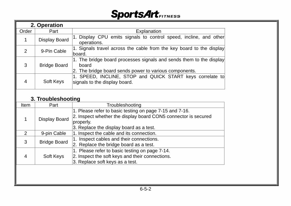
2. Operation
r Orde ExplanationPart
1 Displ Boa play ay rd operatio1. Dis CPU emits signals to control speed, incline, and other
ns.
2 9-Pin Cable 1. Signals t board. ravel across the cable from the key board to the display
3 Brid Boar1. The brid
ge d board 2. The brid
ge board processes signals and sends them to the display
ge board sends power to various components.
4 So eys 1. SPEED,
thft KINCLINE, STOP and QUICK START keys correlate to
e display board. signals to
3. Troubleshooting Item TroubleshooPart ting
1 Displ Boa
1 ase re2. Inspect w
3. Replace t
ay rd properly.
. Ple fer to basic testing on page 7-15 and 7-16. hether the display board CON5 connector is secured
he display board as a test. 2 th9-pin Cable 1. Inspect e cable and its connection.
3 Brid Boar c ge d 2. Replace
1. Inspect ables and their connections. the bridge board as a test.
4 Sof eys 1. Please re
t the
t Kfer to basic testing on page 7-14.
2. Inspec3. Replac
e soft keys and their connections. soft keys as a test.
6-5-2
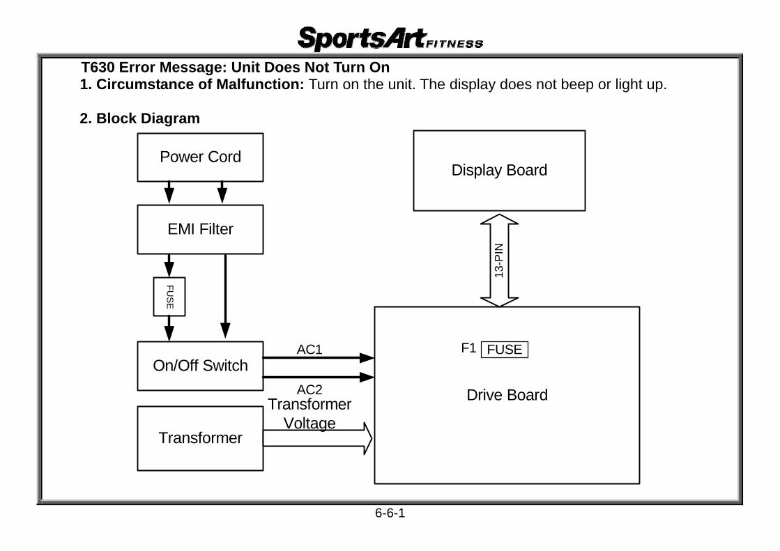
T630 Error Message: Unit Does Not Turn On 1. Circumstance of Malfunction: Turn on the unit. The display does not beep or light up.
2. Block Diagram
Display Board
Drive Board
Transformer
Transformer Voltage
13-P
IN
F1 FUSEOn/Off Switch
EMI Filter
Power Cord
FUS
E
AC1
AC2
6-6-1

3. Operation
r t Orde Operation Par1. oa Display B rd 1. After the display board receives VCC power, the display lights up. 2 13-P Cab eIN le 1. The driv board VBB power travels the data cable to the display.
3 Drive Board a voltage. 1. After st bilizing voltage, the drive board supplies VBB and VCC
4 F1 use 1. The fuseF p otects the drive board by breaking when current is too rhigh.
5 Pow Cord ser 1. Provide power. 6 poEMI Filter 1. Filters wer. 7 seFuse 1. The fu protects the unit by breaking when current is too high.
8 On/O Swit en seeff ch 2. When s
1. Wh t to “0”, the drive board receives no power. t to “1”, AC1, AC2 send power to the drive board.
9 Tra orme nnsf r 1. The tra sformer provides power for drive board circuits.
4. Troubleshooting r t Orde TroubleshoPar oting
1 Disp Boase r
lay ard 2. Inspect
2. Replace
1. Ple efer to basic testing, pages 7-15 and 7-16. whether display board CON1 is connected properly. the display as a test.
2 13-PIN DatCable
a 1. Inspect whether the data cable and its connections.
3 Drive Boar
se r2. Inspect d
d d
5. Replace
d 3. Inspect4. Inspect
1. Plea efer to basic testing, pages 7-4 and 7-7. rive board CON2, CON3 connections. rive board AC1, AC2 connections. rive board CON1 connections. the drive board as a test.
6-6-2

5. Troubleshooting r t Orde TroubleshoPar oting
4 ct F1 Fuse 1. Inspe whether the F1 fuse has blown.
5 Po Cor ct t wer d 2. Inspect
1. Inspe he power cord connection. whether the power cord is connected to the unit properly.
6. e rEMI Filter 1. Pleas efer to basic testing on page 7-1.
7 Fuse and FHolder
ct
lace
use 2. Inspect t3. Rep
1. Inspe whether the fuse has blown. he fuse holder wire connections. the fuse as a test.
8 On/ Swi
1. When th2. If not,
3. Replace
Off tch connection
e on/off switch is on “1”, does the switch light up? inspect the power cable connections and EMI filter
s. the on/off switch.
9 Tra orme1. Please r
tnsf r 2. Inspectefer to basic testing page 7-4. he transformer cable and its connections.
6-6-3
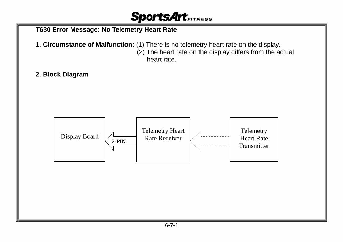
T630 Error Message: No Telemetry Heart Rate 1. Circumstance of Malfunction: (1) There is no telemetry heart rate on the display.
(2) The heart rate on the display differs from the actual heart rate.
2. Block Diagram
Telemetry Heart Rate Transmitter
Telemetry Heart Rate Receiver 2-PIN
Display Board
6-7-1

3. Operation
r rt Orde Operation Pa1 Display Board 1. The display shows the heart rate value after receiving it. 2 2- CaPIN b ele 1. The h art rate signal travels the cable to the display board.
3 H t RatRec er
eear e Board
1. The hsignal to teiv
art rate receiver board receives and transmits the heart rate he display board.
4 Heart RatTr smitte
ree r
it to the an
1. The heart rate transmitter strap detects the user’s pulse and transmits ceiver board.
4. Troubleshooting
t Order Par Troubleshooting
1 Dis y Bospect
tpla ard 2. Inspec3. Replac
1. In whether the display CON3 cable is connected properly. the U6 IC connection. Replace as a test. e the display board as a test.
2 2- Cab t PIN le 1. Inspec the cable and its connections.
3 H t RatRec e B
eear e c oard
1. Replaeiv
the receiver board as a test.
4 Heart RTr smitte ce
ate e r
1. Pleas2. Replaan
refer to basic testing on page 7-17. the transmitter as a test.
6-7-2

T630 Error Message: Incline Does Not Operate Up or Down 1. Circumstance of Malfunction: After pressing the incline key, the display incline values change
but the incline does not operate up or down.
2. Block Diagram
Display Board
Drive Board
LED9 INC_UP
Incline Up/Down Signal
Incline Motor
13-P
IN
AC Incline Motor Voltage
LED7 INC_DN
LED8 ZERO
FUSE3-PIN
F2
6-8-1

3. Operation
r Part Orde Operation
1 D lay The oisp Board board t
1. display board CPU sends INCLINE command signals to the drive control incline operation.
2 1 PIN I3- Cable 1. INCL NE command signals travel the display board to the drive board.
3 ve BoDri ard 1. After in
processing incline command signals, the drive board emits voltage to cline motor, making it operate. the
4 IN C a3-P able 1. Volt ge travels the three-in cable from the drive board to the incline motor.
5 I ine nnncl Motor 2. Whe
1. Whe the drive board INC_UP indicator lights, the incline operates up. the drive board INC_DN indicator lights, the incline operates down.
4. Troubleshooting
rOrder Troubles Pa t hooting
1 Di ay B
nspeINCL<
3. Repla
spl oard 2. Inspe
1. I ct whether incline window values change when you press >/<>.
ct whether the display CON1 cable is connected properly. ce the display board as a test.
2 13 N C c-PI able 1. Inspe t the 13-pin data cable and its connections.
3 D e Bo
e2. Inspec
c3. Repla
riv ard 2. Inspe
1. Pleas refer to basic testing, page 7-8. t CON2, CON3 cable connections on the drive board. t CON6, CON7 connections on the drive board.是否接好
ce the drive board as a test. 4 3- N Ca cPI ble 1. Inspe t the 3-pin incline cable and its connections.
5 In e M seclin otor 2. Repla1. Plea refer to basic testing, page 7-13.
ce the incline motor as a test.
6-8-2

T630 Error Message: Main Fuse Broke 1. Circumstance of Malfunction: (1) Main fuse is broken. Turn on unit power.
Display does not light up. (2) Replace the fuse. Turn on power. The fuse breaks again.
2. Block Diagram
Display Board
Drive BoardOn/Off Switch
EMI Filter
FUS
E
AC1
AC2
LED1 POWER1
LED2 PWR
6-9-1

3. Operation
t Order Par Operation 1 t esEM FilI er 1. Provid voltage from the exterior power supply.
2 Fuse d an Fuse 1. When thbreaks. Holder
e drive board or other components malfunction, the fuse
3 On/O Swit n th ff ch provided to
1. Whe e “-” side on the On/Off switch is pressed, exterior power is the drive board.
4 Drive Board 1. If there isis 2. If there
no component malfunction, the display operates normally. a component malfunction, the drive board shorts out.
4. Troubleshooting
t Order Par Troubleshooting
1 EMI Fil ase r tter 2. Inspect
1. Ple efer to basic testing, page 7-1. he wire connectors at the EMI filter.
2 Fuse and Fuse de
t tt tHol r
1. Inspec2. Inspec
he fuse specifications: Is the fuse the correct type? he fuse holder.
3 On/O Swff itch 1. Inspect the power supply cord connections.
4 Drive Board 2. Inspect t t
4. Replace
3. Inspect
1. Inspect the drive board wire connections. he drive board bridge rectifier BD1 for a short. he drive board IGBT for a short. the drive board if necessary.
6-9-2

T630 Error Message: Service Required 1. Definition: The motor has overheated. The unit is operating in a protective mode.
2. Block Diagram
Display
Drive Board
Motor
Thermal Sensor Signal
LED10_MT-OTP Thermal Sensor
Thermal Sensor Signal
6-10-1

3. Operation r art Orde OperatioP n
1 Motor The al
When t.
rm Sensor 2. When open.
1. the thermal sensor is not too hot, the sensor circuit is an electrical
eshor
th thermal sensor is too hot, the sensor circuit is an electrical
2 D e Bo veriv ard The dri board sends the thermal sensor signal to the display. 3 D a Ca hat b tle 1. The ermal sensor signal travels from the drive board to the display.
4 Di ay B spl oard 2. If theService R
1. The display CPU detects the thermals sensor signal. thermal sensor circuit is an electrical open, the display shows equired and beeps.
4. Troubleshooting
Order Part Troubleshooting
1 Walk Belt 1. Add lubrication as a test. 2. Adjust walk belt tightness. 3. Inspect the walk belt wear. Replace if necessary.
2 Walk Deck and Front and Rear
Rollers
1. Clean the front and rear rollers. 2. Inspect the walk deck for wear. Replace if necessary.
3 Motor
1. Inspect the motor cable and its connection. 2. When the display shows Service Required, inspect whether the
motor is too hot. If so, inspect the walk belt, deck, and motor. 3. Inspect the motor brushes for wear. Replace if necessary. 4. Replace the motor as a test.
4 Drive Board 1. Inspect the motor thermal sensor cable and its connections. 2. Replace the drive board as a test.
6-10-2

T630 Error Message: Heart Touch Rate (HTR) Malfunction 1. Circumstance of Malfunction: (1) Place both hands on the HTR contacts.
Display shows no reaction. (2) Do not place hands on the HTR contacts. Display shows a
heart rate value.
2. Block Diagram
Display Board HTR Board4-PIN
HTR Contact (Right)
Heart Rate Signal
HTRContact (Left)
2-PIN
2-PIN
5-PINCON4
6-11-1

3. Operation
Order Part Operation 1 C HTR ontact 1. HTR contact pads detect the user’s pulse.
2 PIN C on2- able pads
1. The signal travels through two, 2-pin cables, one connected to the contact each side.
3 PIN C 5- able 1. The 2-pin cable connects to a 5-pin cable, which connects to the HTR board.
4 TR B e H oard 2. Th
1. The HTR board detects the heart rate signal. HTR board sends the heart rate signal to the display board.
5 PIN C 1. The C4- able 2. VC
HTR board signal travels via the 4-pin cable to the display board. power supply travels to the HTR board.
6 playDis Board 1. The display shows the heart rate value.
4. Troubleshooting
Order Part Troubleshooting
1 HTR Bo 1. Cleanest tard 2. T
the HTR contact pad. he HTR cable.
2 -PIN C nspe2 able 1. I ct the cable and its connections. 3 -PIN C nspe5 able 1. I ct the cable and its connections.
4 HTR Bo nspeReplaard 2.
1. I ct the 4-pin cable from the HTR board to the display board. ce the HTR board as a test.
5 -PIN C nspe4 able 1. I ct the cable and its connections.
6 isplay
1. Inspe2. Inspe
epla4. Repla
D Board 3. R
ct the display CON4 cable connection. ct the display board U2 IC connection. ce IC U2 or U4 40106 as a test. ce the display board as a test.
6-11-2

T630 Error Message-Safety Key Does Not Operate
1. Circumstance of Malfunction:(1) Put Safety Key in place. Unit has no reaction. (2) Do not put Safety Key in place. Unit operates as if the key was
in place. 2. Block Diagram
Display Board
Safety Key Board
Safety Key
5-12-01

3. Operation
Order Part Operation
1 Saf Key use th exety 1. To e machine, put the safety key in place. Turn on the unit.
2. While ercising, remove the safety key. They unit stops.
2 Safety Key
1. If the safand the
theical
h the open circ
Board
ety key is in place, the reed switch on the safety key board magnet creates an electrically closed circuit.
2. With electr
3. Wit
safety key in place, the reed switch creates a closed circuit. The unit can be operated. safety key not in place, the reed switch is an electrically uit. The unit cannot be operated.
3 Safety Key y heCable
The safetcable to t
key board reed switch status is transmitted through the display.
4 Display BoaU d
rd 1. If the saf2. I the saf
The CP etects the safety key status. ety key is in place, the treadmill can operate.
f ety key is not in place, the treadmill does not operate.
4. Circumstance of Malfunction
TroubOrder lPart eshooting 1 hSafety Key Inspect w ether the safety key magnet for magnetism.
2 hSafety Key Board
Test whet er the safety key board reed switch operation.
3 the Cable Inspect cable connections.
3 Displ Bo ect way ard 2. Inspect t1. Insp hether the IC chip is inserted properly.
he safety key circuit condition.
5-12-02

Testing-EMI Filter
(1) A to B Test (2) C to D Test
C A
B D
7-1-1

(3) A to E Test
Test Procedure 1. Remove wires from the filter. 2. Set voltmeter to the 200 ohm setting. Place probes as indicated. 3. Normal test results are shown below.
Test Points Normal Reading Explanation 1. A-B 0 (continuity) There should be continuity. OL means the line connection is broken. 2. C-D 0 (continuity) There should be continuity. OL means the line connection is broken. 3. A-E 1 or OL (open line) OL open line is normal. Continuity here indicates a short.
A
E
7-1-2

Troubleshooting 1. Continuity test: If there is not continuity during the A-B and C-D tests, the filter is bad. Replace it. 2. Open test: If there is a short across A-E, the filter is bad. Replace it.
7-1-3

Testing-DC Motor
Test Procedure 1. Remove motor M+, M- wire connections from the drive board. 2. Set multimeter to the 200 VDC setting. Place probes on the M+, M- wire connectors. 3. Rotate the motor. Motor should produce voltage. If there is no voltage, the motor has an electrical “open.” Inspect the motor brushes and commutator.
7-2-1

Testing-Transformer Voltage
1.Test Configuration
Drive Board
CON1 Transformer Connections
7-3-1

Test Procedure 1. Inspect transformer wire connections at the drive board CON1 connector. 2. Set multi-meter to the AC 200V setting. 3. Turn on unit power. Place multi-meter probes on the connector for the transformer’s two red wires (or two blue wires on
a 220V unit) as shown. 4. Normal reading: AC 110V North America (or 220V Europe). 5. Test secondary (output) voltages in order. Note normal specifications below.
Inspection Points 1. If the transformer primary (red wires for 110V power supply or blue wires for 220V power
supply) have no voltage, there is no incoming voltage to the transformer. Inspect F1 3A fuse on the drive board. 2. If any of the secondary wires have no voltage, the transformer is bad.
Transformer Wires Red probe Black probe Voltage (AC)
RED/(BLUE) RED/(BLUE) 110V (Red)/220V(Blue) BLACK BLACK 12-13V WHITE WHITE 12-13V
ORANGE ORANGE 18-20V YELLOW YELLOW 10-12V
7-3-2

Testing-Inductor
Test Procedure 1. Remove the inductor wires from the drive board. 2. Set voltmeter to the ohm setting. Place probes separately on the wire connectors. 3. Normal reading: 10 ohm or less. 4. If there is no reaction, the inductor has an electrical open. Replace it.
7-4-1

Testing-DC Motor Voltage
1. Test Configuration
7-5-1

Test Procedure 1. Set voltmeter to the 200 VDC setting. Place probes separately on the M+, M- terminals. 2. Turn on treadmill. Press SPEED<> up. Motor rotates.
Normal reading at the lowest speed: 0.2 KPH (0.1 MPH), 5.5-6.5V (110V) or 9-11V (220V). Normal reading at highest speed: 20.0 KPH (12.0 MPH), 100-120V (110V) or 210-230V (220V).
3. If the drive board does emit voltage, the motor cannot operate. The problem is in front of the motor.
Inspect If the motor does not operate: 1. If the drive board EMG indicator lights, IGBT has an electrical short. Test the IGBT. 2. Replace the drive board and test.
7-5-2

Testing-Drive Board IGBT
Component and LED Indicator Placement
Q2 Q3
LED11 Current Restriction Indicator
7-6-1
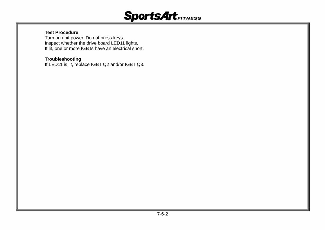
Test Procedure Turn on unit power. Do not press keys. Inspect whether the drive board LED11 lights. If lit, one or more IGBTs have an electrical short. Troubleshooting If LED11 is lit, replace IGBT Q2 and/or IGBT Q3.
7-6-2

Testing-Drive Board VCC Power
Drive Board VCC Power Indicator Placement
LED2 VCC
7-7-1

Test Procedure 1. Turn on unit power. Power switch lights up. 2. Drive board LED2 lights. Troubleshooting If the drive board VCC power indicator does not light: 1. Inspect AC1, AC2 wire connections. 2. Inspect transformer wire connections. 3. Inspect whether fuse F1 2A is broken. Replace if necessary. 4. Inspect CON2, CON3 connections and wires.
7-7-2

Testing-Drive Board Incline Motor Power
LED7 INC_DN
LED9 INC_UP
7-8-1

Test Procedure 1. Put voltmeter to the 600 VAC setting. Place the red probe on the CON6-WHITE wire pin. To test for up voltage,
place the black probe on the CON6-BLACK wire pin. To test down voltage, place the probe on the CON6-RED wire pin.
2. Turn on power. Press QUICK START or another mode of operation. 3. Press INCL<>. The drive board INC_UP LED lights. Normal reading: 108~110V (220V: 215~220V). Incline
operates upward. 4. Press INCL<>. The drive board INC_DN LED lights. Normal reading: 108~110V (220V: 215~220V). Incline operates downward. 5. If there is no voltage, the drive board may be defective. Inspection Points Press INCL<>. The drive board INC_UP LED lights. CON6 emits AC voltage. If not: 1. Inspect whether LED9 lights. 2. Inspect whether K5 RELAY activates. 3. Inspect the F2 3A fuse on the drive board. 4. Inspect whether Q15 BT137 is burnt. Press INCL<>. The drive board INC_DN LED lights. CON6 emits AC voltage. If not: 1. Inspect whether LED7 lights. 2. Inspect whether K5 RELAY activates. 3. Inspect the F2 3A fuse on the drive board. 4. Inspect whether Q15 BT137 is burnt.
7-8-2

Testing-Incline Limiter Switch
Test Configuration
LED8 ZERO Indicator
7-9-1

Test Procedure Put voltmeter to the 20K Ω setting. Place probes on the calibration switch pins. Touch the switch to activate it. Normal reading: 0 Ω. Turn on power. Touch the switch again. LED8 ZERO lights. Inspection Points If not as above, replace the switch and test again.
7-9-2

Testing-Optic Sensor Signal
Test Configuration
LED6 MC Indicator
Optic sensor board
Optic sensor wheel
7-10-1

Test Procedure 1. Make sure that the optic wheel spins in the middle of the optic sensor nibs and that there are no broken or bent
teeth. 2. Inspect whether the optic sensor wire is connected properly. 3. Turn on power. Do not press any keys. Turn the motor slowly with your hand. The drive board MC indicator lights. 4. If the MC indicator does not flash, the optic sensor is bad. Replace it.
Inspection Points If when the motor spins, the MC indicator on the drive board does not light, inspect: 1. whether the optic wheel spins in the middle of the optic sensor nibs. 2. whether the optic wheel has missing, broken, or bent teeth.
the optic sensor wire connections. 3. replace the optic sensor and test unit operation.
7-10-2

Testing-Optic Sensor Signal LED
Test Configuration
LED6 MC Indicator
Optic Sensor
Optic Wheel
7-11-1

Test Procedure 1. Inspect whether the optic sensor wires are connected properly. 2. Turn on unit power. Do not press any keys. Rotate the motor slowly. 3. When the optic wheel moves, LED6 MC on the drive board flashes. 4. If the drive board MC LED does not flash, the optic sensor signal is malfunctioning. Inspection Points If the MC indicator on the drive board does not flash when the motor moves, inspect: 1. wire connections from the optic sensor to the drive board. 2. replace the optic sensor as a test.
7-11-2

Testing-AC Incline Motor Resistance
Fig. 1
Test Position 1 Test Position 2
7-12-1

Test Configuration
Fig. 2
7-12-2
Test Position

Test Procedure 1. Remove the AC incline motor wire connection from the drive board. 2. Put voltmeter to the 200 ohm setting. Place probes separately on the red and white wires of the AC
wires as shown in Fig. 1. Normal reading: 22.5 ohm or less. (Readings on black and white are the same.) 3. Place probes separately on red and black wires as shown in Fig. 2. Normal reading: 43.5 ohm or less. 4. If there is no reading, the incline motor is bad.
Circumstance of Malfunction 1. Press INCLINE<> or INCLINE<> key. Incline fails to operate. After about 35 seconds,
ERR7 appears.
7-12-3

Testing-Display Board VBB Circuit
7-13-1

Test Procedure 1. Turn on power. Drive board LED2 lights. 2. Put multi-meter to the DC 20 VDC setting. Place probes as shown. 3. Normal reading: about 15~16 VDC.
Inspection Points If there is not 15~16 VDC, inspect: 1. Data cable wire connections from the drive board to the display board. 2. Whether the data cable is pinched or broken. 3. Replace drive board component BD3 KBU1006 and test operation.
7-13-2

Testing-Display Board VCC Circuit
LED1 POWER Indicator
7-14-1

Test Procedure 1. Turn on power. Drive board LED2 lights. 2. Put voltmeter to the DC 20 VDC setting. Place probes as shown. 3. Display board LED1 lights. Normal reading: 4.9~5 VDC. 4. Display beeps once and lights up.
Inspection Points If after turning unit power, the LED1 POWER indicator on the display and other display windows do not light, inspect:1. whether there is VCC voltage 2. replace D14 UF5406G or U5 SK8051S and test operation.
7-14-2

Testing-Telemetry Heart Rate
Telemetry Receiver Board (under display)
Heart rate telemetry transmitter
7-15-1

Static Test 1. Wear the telemetry strap in properly. 2. Turn on unit power. Stand on walk belt about 80 cm from the display. 3. After five seconds, the display shows heart rate value.
Active Test 1. Wear the telemetry strap in properly. 2. Press SPEED<> or <> key to set the SPEED setting. 3. After the walk belt starts to rotate, run on the walk belt about 80 cm from the display. 4. After five seconds, the display shows heart rate value.
Inspection Points If the static test failed, inspect: 1. Wires from the display to the telemetry receiver board. 2. Replace the telemetry strap and test again.
If the static test passed but the active test failed, inspect: 1. The telemetry strap. Batteries may be low. The strap might not be fastened securely. 2. Replace the telemetry strap and test again.
7-15-2

Testing-HTR Board LED Indicators
Indicator Color Indicates Explanation LED1 Red Telemetry heart rate signal Flashes to indicate incoming telemetry signal LED2 Green HTR handlebar signal Lights to indicate hands on HTR grips LED3 Orange HTR heart rate Flashes to indicate incoming HTR signal LED4 Red Outgoing heart rate signal Each flash indicates an outgoing heart rate signal
LED2 LED3 LED4 LED1
7-16-1

Test Procedure 1. Do not hold HTR grips. No LEDs on the HTR board light. 2. Hold the HTR grips with both hands. HTR board LED2 lights. 3. When the HTR signal enters the board, LED3 flashes. 4. When the HTR board emits the HTR signal to the display, LED4 flashes. 5. Within ten seconds, the heart rate window displays a heart rate value.
Inspection Points If not as above, refer to the chart below.
Order n e g Malfunctio Caus Troubleshootin
1 ht e es LED1 does not lig No telemetry signal is entering thboard. Telemetry transmitter, wir
2 ht s. d. LED2 does not lig No one is holding HTR grip HTR grips, wires from grips to HTR boar
3 ht d. d. LED3 does not lig No HTR is entering the boar HTR grips, wires from grips to HTR boar
4 ht R rd LED4 does not lig The HTR board is not emitting an HTsignal. HTR boa
5 o y No heart rate display
on board is not sending a signal tthe display. HTR 3-pin cable, displa
7-16-2

Testing - HTR Handlebar Continuity (3-pin cable to HTR handlebars)
1. Do not turn on unit power. Disconnect the 3-pin wire connectors from the HTR board. 2. Put voltmeter to the 200 ohm setting. Place probes as shown. 3. Test configuration
Signal Line Continuity Test Ground Line Continuity Test Te s st Point Normal Reading Te s st Point Normal Reading A-a Continuity A-GND Open A-b Open Frame to GND Open
Fig. 1 Fig. 2
(HTR board 3-pin cable)
a
GND A
b
7-17-1

Test Procedure 1. Do not hold HTR grips. No LEDs on the HTR board light. 2. Hold the HTR grips with both hands. HTR board LED2 lights. 3. When the HTR signal enters the board, LED3 flashes. 4. When the HTR board emits the HTR signal to the display, LED4 flashes. 5. Within ten seconds, the heart rate window displays a heart rate value.
Inspection Points
1. If not as above, refer to the chart below.
Order n e g Malfunctio Caus Troubleshootin
1 s LED1 does not light No telemetry signal is enteringthe board. Telemetry transmitter, wire
2 . . LED2 does not light No one is holding HTR grips HTR grips, wires from grips to HTR board
3 . . LED3 does not light No HTR is entering the board HTR grips, wires from grips to HTR board
4 n d LED4 does not light The HTR board is not emitting aHTR signal. HTR boar
5 y No heart rate display
on HTR board is not sending asignal to the display. 3-pin cable, displa
7-17-2

T630 Treadmill Walk Belt Adjustment Walk belt adjustment is needed when the belt tracks too much to one side or when the belt is too loose or tight.
Step 1. Set speed to 4 KPH/ 2.5 MPH.
Step 2. The walk belt should rotate in the center of the deck with equal space on both sides. To adjust a walk belt that tracks improperly to one side, turn one adjustment screw. Example: If the walk belt tracks to the right side, turn the right adjustment screw clockwise. This adjusts the right side of the rear roller toward the back, pushing the walk belt to the left side. Likewise, turning the left adjustment screw clockwise would make the walk belt move toward the right side.
A B
Step3. To increase or decrease walk belt tightness, turn adjustment screws on both sides. Turning adjustment screws clockwise pulls the belt tighter. Turning counterclockwise makes the belt looser. Tip: To maintain tracking when tightening or loosening a walk belt, simultaneously turn adjustment screws on both sides an equal amount.
8-1-1

T630 Treadmill Walk Belt Tightness Adjustment
Step 1: Set speed to 4 KPH/2.5 MPH.
Step 2: If belt tends to one side, adjust one side only until the margin (A&B) on both sides is
the same.
Clockwise tightens belt
Counter- clockwise loosens belt
A B
8-1-2

T650/T650M Treadmill Walk Belt Tightness Adjustment Step 3: Test belt tightness by lightly bearing against it.
Step 4. If too loose, turn adjustment screws on both sides equally one half to one turn. If too tight,turn adjustment screws on both sides counterclockwise one half to one turn.
Notes:
When you test belt tightness, if the motor operates normally, 1. But the walk belt can be stopped for more than ½ second, the walk belt is too loose.
Simultaneously rotate both adjustment screws clockwise 1/2 to one turn. Test again. Adjust until the walk belt slips briefly but quickly regains traction and begins to rotate.
2. And the walk belt cannot be stopped or slowed whatsoever, the belt may be too tight. Simultaneously rotate adjustment screws counterclockwise 1/2 to one turn. Test again.
8-1-3
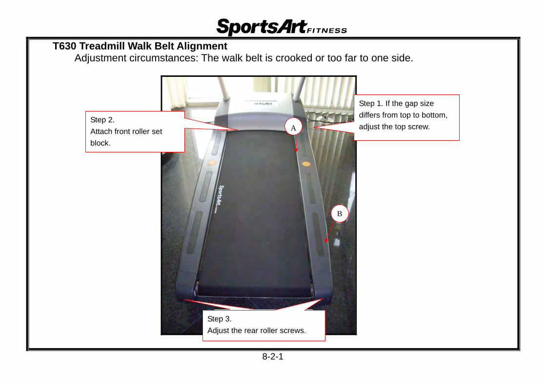
T630 Treadmill Walk Belt Alignment
Adjustment circumstances: The walk belt is crooked or too far to one side.
Step 1. If the gap size differs from top to bottom, adjust the top screw.
Step 2. Attach front roller set block.
A
B
Step 3. Adjust the rear roller screws.
8-2-1

Step 1. Adjust left/right rear roller screws.
2. Adjust the walk belt left/right adjustment screws.
Step 2:1.Use a tool to pry the front roller tight.
2. Install the front roller adjustment block, adjusting its position with the screw.
8-2-2

Step 3:1. Adjust rear roller adjustment screws. 2. Job complete: a straight walk belt.
8-2-3

T630 AC Motor Incline Software Calibration Procedure
1. Test Configuration
8-3-1

2. Software Calibration and Testing (1) Press INCL<> key until the incline window shows 15%. When the incline operates up, LED9
on the drive board lights. When the incline stops moving, LED8 extinguishes. (2)Press INCL<> key until the incline window shows 0%. When the incline operates down,
LED7 on the drive board lights. When the incline stops moving, LED8 extinguishes. (3)When the drive board LED8 ZERO indicator lights, incline calibration has been completed.
3.Calibration when not in Operation (1) In QUICK START mode, press the STOP key. Or, in the PROGRAM mode, press the STOP key three
seconds. (2)Turn off unit power. Then turn on unit power. (3) When the model number scrolls across the display, the incline declines until the calibration switch is hit, then
the drive board LED8 ZERO indicator lights. In operation, the INCLINE window shows 0%, indicating incline calibration has been completed.
8-3-2

T630 AC Incline Motor Calibration – Hardware Calibration Procedure
Step 1. Set the unit onto a block.
Step 2. Disconnect the calibration switch wire..
Step 3. Remove the incline motor cover.
Step 4. Press INC DN key until the incline declines fully. Then turn off unit power.
8-4-1

Step 5. Set off the AC incline motor down limiter.
Step 6. Remove CON6 and the ground connector.
Step 7. Remove the R-clip and lower incline pin.
Step 8. Remove the hitch pin and upper incline pin.
8-4-2

Step 9. Remove the AC incline motor set.
Step 10. Set the distance between holes to 264 mm.
Step 11. After calibrating the incline,
reinstall the incline. Connect wires.
Step 12. Press the INC UP key to 2% and stop. Let unit operate.Press the INC DN key to 0% to complete calibration.
264 mm
8-4-3

Step 13. Test Procedure (1) Press INCL<> until the incline window shows 15%. As the incline operates upward, indicator LED 9 lights.
When the incline stops operating, LED8 extinguishes. (2)Press INCL<> until the incline window shows 0%. As the incline operates downward, LED7 lights.
When the incline stops operating, LED8 lights. (3) The LED8 ZERO indicator on the drive board lights to indicate completion of the calibration process.
8-4-4
Top Related