


Languages
Pages
Legal


Studies on Aluminum–Fly-Ash
Composite Produced by Impeller Mixing
A THESIS SUBMITTED IN PARTIAL FULFILLMENT OF THE REQUIREMENTS FOR THE DEGREE OF
Master of Technology
In
Metallurgical & Materials Engineering
Submitted
By
Shuvendu Tripathy Roll No.207MM103
Department of Metallurgical & Materials Engineering National Institute of Technology
Rourkela 2009

Studies on Aluminum – Fly-Ash
Composite Produced by Impeller Mixing
A THESIS SUBMITTED IN PARTIAL FULFILLMENT OF THE REQUIREMENTS FOR THE DEGREE OF
Master of Technology
In
Metallurgical & Materials Engineering
Submitted
By
Shuvendu Tripathy Roll No.207MM103
Under the guidance of Prof.S.Sarkar
Department of National Metallurgical & Materials Institute of Technology
Rourkela 2009

National Institute of Technology
Rourkela
CERTIFICATE
This is to certify that the thesis entitled, “Studies on Aluminum–Fly-AshComposite
Produced by Impeller Mixing”, submitted by Shuvendu Tripathy in partial fulfillment of
the requirements for the award of Master of Technology Degree in Metallurgical and
Materials Engineering at the National Institute of Technology, Rourkela (Deemed
University) is an authentic work carried out by him under my supervision and guidance.
To the best of my knowledge, the matter embodied in the thesis has not been submitted to any
other University/ Institute for the award of any degree or diploma.
Date: Prof.S.Sarkar
Dept. of Metallurgical & Materials Engineering,
National Institute of Technology,
Rourkela

ACKNOWLEDGEMENT
With deep regards and profound respect, I avail this opportunity to express my deep sense of
gratitude and indebtedness to Prof. S. Sarkar , Metallurgical and Materials Engineering
Department, NIT Rourkela, for introducing the present research topic and for his inspiring
guidance, constructive criticism and valuable suggestion throughout in this research work. It
would have not been possible for me to bring out this thesis without his help and constant
encouragement.
I am sincerely thankful to Dr B.B.Verma, Professor and Head metallurgical and Materials
Engineering Department for his talented advice and providing necessary facility for my work.
Last but not the least; I am highly grateful to lab. members of Department of Metallurgical
and Materials Engineering, N.I.T., Rourkela, especially Mr.Heymbram, R. Pattanaik, U.K.
Sahu for their help during the execution of experiment.
Date: Shuvendu Tripathy

CONTENTS
LIST OF FIGURES i
LIST OF TABLES ii
ABSTRACT IV
CHAPTER-1:
1.1 INTRODUCTION 1
CHAPTER-2:
2. LITERATURE SURVEY
2.1. Composite 3
2.2. Classifications of composites 4
2.3. Strengthening mechanism of composite 6
2.4. Interfacial bonding mechanism 8
2.5. Metal matrix composite 10
2.6. Fabrication techniques for metal matrix composites 11
2.7. Role of magnesium in cast aluminiurn alloy matrix composites 16
2.8. Particulate reinforced metal matrix composites 17
2.9. Aluminium -fly ash particulate reinforced composite 20
2.10. Fly ash 23
2.11. Why fly ash 24
2.12. Chemical reaction between al and fly ash 25
2.13. Wear behaviour 26

CHAPTER-3:
3. EXPERIMENTAL WORK
3.1 Raw materials 30
3.2 Melting and casting 30
3.3 Microstructural characterization 31
3.4 Particle size analysis 32
3.5 Mechanical properties observation 33
3.6 Sliding wear behavior 34
3.7 Worn surface and debris examination 34
CHAPTER-4
4. RSEULTS AND DISCUSSION
4.1 fly ash analysis 35
4.2 Optical microstructure of cast composite 37
4.3 SEM micrographs of the MMCs 39
4.4 Distribution of particles in MMCs 41
4.5 Mechanical properties determination 43
4.6 Wear behavior 45
4.7 Frictional characteristics 49
4.8 Microscopic examination 50
4.9 SEM micrographs of worn surface of the composite 53
4.10 Wear debris 54
4.11 Fractograph of the selected composite 56

CHAPTER-5:
CONCLUSION 57
CHAPTER-6:
REFERENCES 58

i
LIST OF FIGURES
2.1. Schematic diagram showing the contact angle
that describes wettability 8
3.1. Laboratory stir casting set up 31
3.2: JEOL JSM-6480LV scanning electron microscop 32
3.3: Malvern particle size analyzer
(Model Micro-P, range 0.05-550 micron) 33
4.1SEM Micrograph of fly ash used in the study 35
4.2. Particle size analysis of fly ash 36
Optical micrographs of MMCs
4.3. Al+ 5% fly ash composite 37
4.4. Al+ 10% fly ash composite 37
4.5. Al+15% fly ash composite 37
4.6. Al+20% fly ash composite 37
4.7. Al+2%Si+10% fly ash composite 38
4.8. Al+2%Mg+10% fly ash composite 38
SEM micrographs of MMCs
4.9. Al+ 5% fly ash composite 39
4.10. Al+ 10% fly ash composite 39
4.11. Al+15% fly ash composite 39
4.12. Al+ 20% fly ash composite 39
4.13. Al+2%Si+10% fly ash composite 40
4.14. Al+2%Mg+10% fly ash composite 40
4.15. Macrographs showing distribution of particles 41
4.16. Graph showing variation in hardness with
composition of MMCs 43

ii
4.17-Wear behavior of MMCs with different
composition under normal load of 10N 45
4.18-.Wear behavior of MMCs with different
composition under normal load of 15N 46
4.19-Wear behavior of MMCs with different
composition under normal load of 20N 47
4.20- Wear behavior of MMCs with variation in normal load 47
4.21- Variation of behavior of MMCs with variation
in sliding velocity 48
4.22- Variation of coefficient of friction with
composition of the composite 49
4.23-Grooves and scratch marks indicating abrasion wear 50
4.24- Deep smooth and large grooves under higher loads 50
4.25- Wear debris filling the valleys in the wear surface 51
4.26- Delamination of wear surface under a loadof 20N 52
4.27—SEM micrographs of the worn surfaces after the wear test under velocity
1 m/s; time 30min; (a) load 10N and (b) 20N. 53
4.28-SEM micrographs of debris of the MMCs at different loads at (a) 10N, (b)
15Nan(c) 20N 54
4.29-SEM fractograph of Al+2%Mg+10%fly ash 56

iii
LIST OF TABLES
2.10. Chemical Requirements for Fly Ash Classification 23
4.1. Chemical composition of fly ash 35
4.2. BHN values of the samples 43
4.3. Tensile properties of the unreinforced alloys and its composite 44

iv
ABSTRACT
Metal matrix composites (MMCs) constitute an important class of design and weight-
efficient structural materials that are encouraging every sphere of engineering applications.
There has been an increasing interest in composites containing low density and low cost
reinforcements. Among various discontinuously dispersed solids used, fly ash is one of the
most inexpensive and low density reinforcement available in large quantities as solid waste
by-product during combustion of coal in thermal power plants. Hence, composites with fly
ash as reinforcement are likely to overcome the cost barrier for wide spread applications in
automotive and small engine applications. To produce Al matrix cast particle composites,
wettaility of the ceramic particles by liquid Al is essential. To improve wettabilty, elements
such as Mg and Si are added into Al melt to incorporate the ceramic particles. The present
investigation has been focused on the utilization abundant available industrial waste fly ash in
useful manner by dispersing it into aluminium/aluminium-magnesium/aluminium-silicon
matrix to produced composites by liquid metallurgy route. Wide size range (0.1-100µm) fly
ash particles were used. These composites were observed with the help of optical
micrography, x ray micro analysis, x ray diffraction, wet chemical analysis, and image
analysis. The dry sliding wear behavior of the composites in the cast conditions was studied
at different loads and different sliding velocities with the help of Pin-On-Disc wear test
machine. The worn surfaces and wear debris were analyzed using optical microscope and
scanning electron microscope. The mechanical properties such as hardness and tensile
strength have been investigated.

1
CHAPTER-1
Introduction
Conventional monolithic materials have limitations with respect to achievable combinations
of strength, stiffness, and density. In order to overcome these shortcomings and to meet the
ever-increasing engineering demands of modern technology, metal matrix composites are
gaining importance. In recent years, discontinuously reinforced aluminum based metal matrix
composites have attracted world wide attention as a result of their potential to replace their
monolithic counterparts primarily in automobile and energy sector. [1]
The basic idea is that continuous fiber reinforced composite has better strength but the
processing methods is highly expensive which hinders their adoption. The continuous fiber
reinforced composites do not allow secondary forming such as rolling, forging and extrusion.
As results of these limitations new efforts on the research of discontinuous reinforcements
have been used. [2, 3] At early stages of development of metal matrix composite emphasis
was given on the preparation of fiber reinforced composite only. But due to the high cost
associated with the process of production, anisotropic properties of the resultant composite
and difficulties associated with the fabrication process, production of this type of composites
has been limited. Now a days the particulate reinforced Al matrix composite are gaining
importance because of their low cost with advantage like isotropic properties. The
strengthening of aluminum alloys with dispersion of fine ceramic particulate composite
materials were developed as an alternative of unreinforced alloy, for obtaining materials with
high stiffness (high strength/modulus and low density) with special interest for the wear
resistant and structural applications. [4, 5] The dispersion strengthened alloys can be
classified, based on the size and volume % of particles uniformly dispersed in the matrix.
Aluminum alloys reinforced with ceramic particles exhibit superior mechanical properties to
unreinforced Al alloys and hence are candidate for engineering applications. The aluminum
metal matrix composites are produced either by casting route or by power metallurgy. The
former has the advantages of producing the composites as lower cost of production and
possibility of producing larger components. However, the inherent difficulties of casting
route are non wettability of ceramic particles by liquid aluminum [6], segregation of particles,
higher porosity level and extensive inter-facial reaction due to higher processing temperature.
Wettabilty of the particles can be improved by coating the particles with metals such as Ni
and Cu, addition of active elements such as Mg into liquid aluminum or preheating of the

2
particles before addition into liquid aluminium [6]. The most conventional method of
production of composites by casting route is vortex method, where the liquid aluminum
containing 2-5% Mg is stirred with an impeller and ceramic particles are incorporated into
vortex formed by stirring of the liquid metals. Addition of Mg into the liquid metal reduces
the surface tension [7] and there by avoids the rejection of the particles from the melts. With
out addition of Mg recovery of the particles into the melt is quite low. Hence 2-5% Mg is
generally added into the Al melts before incorporation of the particles. However, the
chemistry of the particles of an Al alloy is changed with addition Mg that can be deleterious
to the mechanical properties of the composites.
The present investigation has been focused on utilization of waste fly ash in useful manner by
dispersing it in aluminum matrix to produce composite. In the present work, fly-ash which
mainly consists of refractory oxides like silica, alumina, and iron oxides, was used as the
reinforcing phase and to increase the wetabbility magnesium and silicon were added.
Composites were produced with different percentages of reinforcing phase. Further, these
composites were characterized with the help of, optical micrography, x ray micro analysis, x
ray diffraction, wet chemical analysis, and image analysis. Mechanical and wear properties of
the composites were also evaluated.

3
CHAPTER-2
2. Literature Review
2.1 Definition of composite material:
The composite material can be defined as the system of material consisting of a mixture of
combination of two or more micro constituents insoluble in each other and differing in form
and or in material composition .These materials can be prepared by putting two or more
dissimilar material in such way that they function mechanically as a single unit. The
properties of such materials differ from those of their constituents. These materials may have
a hard phase embedded in a soft phase or vice versa. Normally in the composite material have
a hard phase in the soft ductile matrix where the hard phase act as a reinforcing agent
increase the strength and modulus, and soft phase act as matrix material. The requirement for
satisfying the above mentioned condition is
a. The composite material has to be man-made
b. The composite material must be a combination of at least two chemically distinct materials
with an interface separating the components.
c. The properties of composite should be three dimensionally combined.

4
2.2 Classification of Composites
2.2.1 On the basis of Matrix composite can be classified in the following
groups:
a) Polymer-matrix composites (PMC)
The most common matrix materials for composites are polymeric. Polyester and viny esters
are the most widely used and least expensive polymer resins. These matrix materials are
basically used for fiber glass reinforced composites. For mutations of a large number resin
provide a wide range of properties for these materials .The epoxies are more expensive and in
addition to wide range of ranging commercials applications ,also find use in PMCs for
aerospace applications. The main disadvantages of PMCs are their low maximum working
temperature high coefficients of thermal expansion and hence dimensional instability and
sensitivity to radiation and moisture. The strength and stuffiness are low compared with
metals and ceramics. [9, 10]
b) Metal-matrix composites (MMC)
The matrix in these composites is a ductile metals .These composites can be used at higher
service temperature than their base metal counterparts. These reinforcements in these
materials may improve specific stuffiness specific strength, abrasion resistance, creep
resistance and dimensional stability. The MMCs is light in weight and resist wear and thermal
distortion, so it mainly used in automobile industry. Metal matrix composites are much more
expensive those PMCs and, therefore, their use is somewhat restricted. [9, 10]
c) Ceramic-matrix composites (CMC)
One of the main objectives in producing CMCs is to increase the toughness. Ceramics
materials are inherent resistants to oxidation and deterioration at elevated temperatures; were
it not for their disposition to brittle fracture, some of these materials would be idea candidates
for use in higher temperature and serve- stress applications, specifically for components in
automobile an air craft gas turbine engines .The developments of CMCs has lagged behind
mostly for remain reason, most processing route involve higher temperature and only
employed with high temperature reinforcements[9].

5
2.2.2 On the basics of reinforcement can be classified into three types:
a) Particle reinforced composites
Particulate reinforcements have dimensions that are approximately equal in all directions
.The shape of the reinforcing particles may be spherical, cubic, platelet or any regular or
irregular geometry. These composite can classified under two sub groups [8]:
(i) Large particle composites
(ii) Dispersion strengthened composites
b) Fiber reinforced composites
A fibrous reinforcement is characterized by its length being much greater than its cross-
sectional dimension .However the ratio of length to the cross sectional dimension know as the
aspect ratio, can vary considerably .In single layer composite long fibers with high aspect
ratios give that are called continuous fiber reinforced composites whereas discontinuous fiber
reinforced composites are fabricated using short fibres of low aspect ratio .The orientation of
the discontinuous fibres may be random or preferred .The frequently encountered preferred
orientation in the case of continuous fibre composite is termed unidirectional and the
corresponding random situation can be approximated to by bidirectional woven
reinforcement [10].

6
2.3 Strengthening mechanism of composite
2.3.1 Strengthening mechanism of fiber reinforced composite
Rule-Of-Mixture
Most studies concerned with the evaluation of mechanical behavior of fiber reinforced
composites use what is called a "Rule-Of-Mixtures"(ROM) to predict and/or to compare the
strength properties of the composite The ROM is nothing but an operational tool that uses
weighted volume average of the component properties in isolation to obtain the magnitude of
the property for the composite. Specifically, in the case of composite containing uniaxially
aligned, continuous fibers, the composite stress is written as
σc = σf Vf + σm Vm (1)
Where σ is the axial stress, V is the volume fraction of the component and the subscripts c, f
and m refer to the composite, fiber and matrix, respectively. It is to be noted that
Vf + Vm = 1
Under conditions of isostatic, i.e, the longitudinal strain in the components being equal, one
may write another ROM relationship for the elastic moduli,
Ec = Ef vf + Em Vm (2)
Where E is the elastic modulus and the subscripts represent the components as before. Eq. (2)
neglects any transverse strain arising because of the different contractile tendencies of the
components (i.e, vf = v, where v is Poisson's ratio). However, for metallic systems, the
difference in Poisson's ratio of the two components is generally insignificant and the ROM
values are generally found to be within the limits of the experimental error.
Another example of a property for which ROM works very well is the density ρ. One can
write as ρc = ρf vf + ρm vm (3)
It would appear from these studies that the ROM as applied conventionally to the strength
properties of composites with metallic matrices is not valid. The whole is more than the sum
of individual components in isolation [11].

7
2.3.2 Strengthening mechanism of particulate composite
a) Large-particle composite
Particle-Reinforced Composites can be large-particle and dispersion-strengthened composites
are the two subclassifications of particle-reinforced composites. The distinction between
these is based upon reinforcement or strengthening mechanism. The term ―large‖ is used to
indicate that particle–matrix interactions cannot be treated on the atomic or molecular level;
rather, continuum mechanics is used. For most of these composites, the particulate phase is
harder and stiffer than the matrix. These reinforcing particles tend to restrain movement of
the matrix phase in the vicinity of each particle. In essence, the matrix transfers some of the
applied stress to the particles, which bear a fraction of the load. The degree of reinforcement
or improvement of mechanical behavior depends on strong bonding at the matrix–particle
interface.
b) Dispersion strengthened composite
For dispersion-strengthened composites, particles are normally much smaller, with diameters
between 0.01 and 0.1 m (10 and 100 nm). Particle–matrix interactions that lead to
strengthening occur on the atomic or molecular level. The mechanism of strengthening is
similar to that for precipitation hardening. Whereas the matrix bears the major portion of an
applied load, the small dispersed particles hinder or impede the motion of dislocations. Thus,
plastic deformation is restricted such that yield and tensile strengths, as well as hardness,
improve.

8
2.4. Interfacial bonding Mechanisms
Once the matrix has wet the reinforcement, and is therefore in intimate contact with
reinforcement, bonding will occur A number of different types of bond may formed .The type
of bonding varies from system to system and dependent on fine details such as the presence
of surface contaminates or of added surface active agents .
2.4.1 Adsorption and wetting
Wettability is another significant problem when producing cast metal matrix composites.
Wettability can be defined as the ability of a liquid to spread on a solid surface. Good
wettability means that the liquid (matrix) will flow over the reinforcement covering every
‗bump‘ and dip of the rough surface of the reinforcement and displacing air. It also describes
the extent of intimate contact between liquid and a solid.
(Fig 2.4. Schematic diagram showing the contact angle that describes wettability)
Wettability will not occur if the viscosity of the matrix is not too high and if wetting result in
a decrease in the free energy of the system. Successful incorporation of solid ceramic
particles into casting requires that the melt should wet the solid ceramic phase. The problem
of the wetting of the ceramic by molten metal is one of surface chemistry and surface tension.
The chemistry of the particle surface, including any contamination, or oxidation, the melt
surface and oxide layer must be considered. All the surfaces have associated with the free
energy (per unit area)
γsl= free energy per unit area of solid- liquid interfaces, γsv= free energy per unit area of
solid- vapor interfaces,γlv= free energy per unit area of liquid- vapor interfaces
The spreading coefficient can be defined as
SC= γsv – (γsl + γlv) 1
The bonding force between the liquid and solid phases can be expressed in terms of contact
angle referred to in the Young-Dupre‘s equation [12].
9
γsv= γsl +γlvCosθ 2
Cosθ= (γsv- γsl)/ γlv 3
θ may be used as a measure of the degree of wettability.
(i) θ =1800 , no wettability
(ii) θ =00 , perfect wettability
(iii) 00<θ<180
0, partial wettability
2.4.2 Inter-diffusion
Various types of diffusion process which promote the adhesion can take place at the interface.
The diffusion of free chain ends at the interface between two polymers, which leads to chain
entanglements and a rise in the adhesive strength. Inter diffusion can take place in non
polymeric systems, particularly if it is accompanied by a chemical reaction. The adhesive
strength dependent on the nature of the resultant inters atomic bonds. Inter-diffusion plays
only a minor role at low temperatures, but at elevated temperatures approaching the melting
point of the matrix, inter-diffusion and chemical reaction can result in the formation of brittle
inter metallics which are detrimental to the mechanical properties of MMCs.
2.4.3 Chemical bonding
Various types of chemical reaction may occur at the interface, either deliberately or
inadvertent. These bonds may be covalent, ionic, metallic, etc and in many cases very strong.
These are many examples of inter facial bond strength being raised by localized chemical
reactions. For strong chemical bonding between the reinforcement and matrix a controlled
amount of chemical reaction at the interface is always desirable. However, too thick an inter-
facial zones adversely the mechanical properties of the composites and leads to premature
failure.
2.4.3 Mechanical adhesion
Mechanical interlocking or keying of two surfaces can be lead to reasonable bond. Clearly
the interlocking is greater and hence the mechanical bonding more effective, the rougher the
interface. Also any concentration of the matrix onto the reinforcement is favorable to
bonding. Mechanical bonding plays a major role in load transfer by shear. Two separate
factors affect mechanical adhesion namely (1) Surface roughness, which control the amount
of mechanical interlocking that can occur, and (2) The presence of residual stresses in the
matrix as a result of fabrication. In most cases a purely mechanical bond is not encountered
and mechanical bonding operates in conjunction with another bonding mechanism.

10
2.5 Metal matrix composites
Metal-matrix composites (MMCs) are engineered combinations of two or mote materials
(one of which is a metal) where tailored properties are achieved by systematic combinations
of different constituents. Conventional monolithic materials have limitations in respect to
achievable combinations of strength, stiffness and density .Engineered MMCs consisting of
continuous or discontinuous fibres, whiskers, or particles in a metal achieve combinations of
very high specific strength and specific modulus. Furthermore, systematic design and
synthesis procedures allow unique combinations of engineering properties in composites like
high elevated temperature strength, fatigue strength, damping property, electrical and thermal
conductivities, friction coefficient, wear resistance and expansion coefficient. Structurally,
MMCs consist of continuous or discontinuous fibres, whiskers, or particles in an alloy matrix
which reinforce the matrix or provide it with requisite properties not achievable in monolithic
alloys. In a broader sense, cast composites, where the volume and shape of phase is governed
by phase diagrams, for example, cast iron and aluminum-silicon alloys, have been produced
by foundries for a long time. The modern composites differ in the sense that any selected
volume, shape and size properties in composites like high elevated temperature of
reinforcement can be artificially introduced in the matrix. The modem composites are non
equilibrium combinations of metals and ceramics, where there are fewer thermodynamic
restrictions on the relative volume percentages, shapes and size of ceramic phases. Composite
materials are attractive since they offer the possibility of attaining property combinations
which are not obtained in monolithic materials and which can result in a number of
significant service benefits. These could include increased strength, decreased weight, higher
service temperature, improved wear resistance, higher elastic modulus, controlled coefficients
of thermal expansion and improved fatigue properties. The quest for improved performance
has resulted in a number of developments in the area of MMC fabrication technology .These
includes both the preparation of the reinforcing phases and the development of fabrication
techniques [13].

11
2.6 Fabrication techniques for metal matrix composites
A number of composite fabrication techniques have been developed that can be placed into
four broad categories. These are: (i) powder metallurgical techniques, (ii) liquid metallurgy.
The liquid metallurgy techniques include unidirectional solidifications to produce
directionally aligned MMCs, suspension of reinforcement in melts followed by solidification,
compocasting, squeeze casting, spray casting, and pressure infiltration. The liquid metallurgy
techniques are the least expensive of all, and the multi-step diffusion bonding techniques may
be the most expensive [14].
2.6.1 Powder metallurgical techniques
Powder blending followed by consolidation (PM processing), diffusion bonding and vapor
deposition techniques come under solid state processing Powder metallurgy techniques offer
the following three advantages over liquid metallurgy techniques for fabricating MMCs.[15]
(a) Lower temperatures can be used during preparation of a PM-based composite compared
with preparation of a liquid metallurgy-based composite. The result is lesser interaction
between the matrix and the reinforcement when using the' PM technique. By minimizing
undesirable inter-facial reactions, improved mechanical properties are obtained.
(b) In some cases, PM techniques will permit the preparation of composites that cannot be
prepared by the liquid metallurgy. For instance, fibres or particles of silicon carbide will
dissolve in melts of several metals like titanium, and such composites will be difficult to
prepare using liquid metallurgy techniques.
(c) However, PM techniques remain expensive compared to liquid metallurgy techniques for
the composites like AI-SiC particle composites. In addition, only small and simple shape can
be produced by PM techniques.
Power blending and consolidation
Blending of metallic power and ceramic fibers or particulate has the advantage of close
control over the ceramic content. Blending can be carried out dry or in liquid suspension.
Blending is usually followed by cold compaction, canning, degassing and high temperature
consolidation stage such as hot isostatic pressing (HIP) or extrusion. PM processed AMCs,
contain oxide particles in the form of plate-like particles of few tens of nm thick and in
volume fractions ranging from 0-05 to 0-5 vol% depending on powder history and processing
conditions. These fine oxide particles tends to act as a dispersion-strengthening agent and
often has strong influence on the matrix properties particularly during heat treatment [16].

12
Diffusion bonding:
Mono filament-reinforced AMCs are mainly produced by the diffusion bonding (foil-fibre-
foil) route or by the evaporation of relatively thick layers of aluminum on the surface of the
fibre. 6061 Al-boron fibre composites have been produced by diffusion bonding via the foil-
fibre-foil process [17]. However, the process is more commonly used to produce Ti based
fibre reinforced composites. The process is cumbersome and obtaining high fibre volume
fraction and homogeneous fibre distribution is difficult. The process is not suitable to produce
complex shapes and components.
2.6.2 Physical vapor deposition:
The process involves continuous passage of fibre through a region of high partial pressure of
the metal to be deposited, where condensation takes place so as to produce a relatively thick
coating on the fibre. The vapor is produced by directing a high power electron beam onto the
end of a solid bar feed stock. Typical deposition rates are 5–10 µm per minute. Composite
fabrication is usually completed by assembling the coated fibres into a bundle or array and
consolidating in a hot press or HIP operation. This technique can produced composites with
uniform distribution of fibre and volume fraction as high as 80% [18].
2.6.3 Liquid metallurgy route
Liquid state processes include stir casting or compocasting, infiltration, spray casting and in
situ (reactive) processing. The selection of the processing route depends on many factors
including type and level of reinforcement loading and the degree of micro structural integrity
desired.
Stir casting:
This involves incorporation of ceramic particulate into liquid aluminum melt and allowing
the mixture to solidify. Here, the crucial thing is to create good wetting between the
particulate reinforcement and the liquid aluminum alloy melt. The simplest and most
commercially used technique is known as vortex technique or stir-casting technique. The
vortex technique involves the introduction of pretreated ceramic particles into the vortex of
molten alloy created by the rotating impeller. Lloyd (1999) has reports that vortex-mixing
technique for the preparation of ceramic particle dispersed aluminum matrix composites was
originally developed by Surappa & Rohatgi (1981) [19] at the Indian Institute of Science,
Bangalore. Subsequently several aluminum companies further refined and modified the
process which are currently employed to manufacture a variety of aluminum metal matrix
composites on commercial scale [20].

13
The vortex method is one of the better known approaches used to create and maintain a good
distribution of the reinforcement material in the matrix alloy. In this method, after the matrix
material is melted, it is stirred vigorously to form a vortex at the surface of the melt, and the
reinforcement material is then introduced at the side of the vortex. The stirring is continued
for a few minutes before the slurry is cast. There are different designs of mechanical stirrers.
Among them, the turbine stirrer is quite popular. During stir casting for the synthesis of
composites, stirring helps in two ways: (a) transferring particles into the liquid metal, and (b)
maintaining the particles in a state of suspension.
Micro structural inhomogeneities can cause notably particle agglomeration and sedimentation
in the melt and subsequently during solidification. Inhomogeneity in reinforcement
distribution in these cast composites could also be a problem as a result of interaction
between suspended ceramic particles and moving solid-liquid interface during solidification.
Generally it is possible to incorporate up to 30% ceramic particles in the size range 5 to 100
μm in a variety of molten aluminum alloys .The process is not suitable for the incorporation
of sub-micron size ceramic particles or whiskers. Another variant of stir casting process is
compocasting. Here, ceramic particles are incorporated into the alloy in the semi solid state.
Infiltration process:
Liquid metal is injected into the interstices of the porous preforms of continuous fibre/short
fibre or whisker or particle to produce MMCs. Depending on the nature of reinforcement and
its volume fraction preform can be infiltrated, with or without the application of pressure or
vacuum. MMCs having reinforcement volume fraction ranging from 10 to 70% can be
produced using a variety of infiltration techniques. In order for the preform to retain its
integrity and shape, it is often necessary to use silica and alumina based mixtures as binder.
Some level of porosity and local variations in the volume fractions of the reinforcement are
often noticed in the MMCs processed by infiltration technique. The process is widely used to
produce aluminum matrix composites having particle/whisker/short fibre/continuous fibre as
reinforcement.
In most of the cases the fibres do not act as preferential crystal nucleation sites during melt
solidification .One consequences of this is that the last liquid to freeze , which is normally
solute enriched, tend to locate around the fibres[21].

14
Spray deposition:
Spray deposition techniques fall into two distinct classes, depending whether the droplet
stream is produced from a molten bath (Osprey process) or by continuous feeding of cold
metal into a zone of rapid heat injection (thermal spray process). The spray process has been
extensively explored for the production of MMCs by injecting ceramic particle/whisker/short
fibre into the spray. MMCs produced in this way often exhibit inhomogeneous distribution of
ceramic particles. Porosity in the as sprayed state is typically about 5–10%. Depositions of
this type are typically consolidated to full density by subsequent processing. Spray process
also permit the production of continuous fibre reinforced aluminum matrix composites. For
this, fibres are wrapped around a mandrel with controlled inter fibre spacing, and the matrix
metal is sprayed onto the fibres. A composite mono type is thus formed; bulk composites are
formed by hot pressing of composite mono types. Fibre volume fraction and distribution is
controlled by adjusting the fibre spacing and the number of fibre layers. MMCs processed by
spray deposition technique are relatively inexpensive with cost that is usually intermediate
between stir cast and PM processes.
In-situ processing (reactive processing):
There are several different processes that would fall under this category including liquid-gas,
liquid-solid, liquid-liquid and mixed salt reactions. In these processes refractory
reinforcement are created in the aluminium alloy matrix. One of the examples is directional
oxidation of aluminium also known as DIMOX process. In this process the alloy of Al–Mg is
placed on the top of ceramic preform in a crucible. The entire assembly is heated to a suitable
temperature in the atmosphere of free flowing nitrogen bearing gas mixture. Al–Mg alloy
soon after melting infiltrates into the preform and composite is formed.
Martin–Marietta‘s exothermic dispersion process or the XDTm process is another in-situ
technique for composite processing. XDTm process is used to produce TiB2 reinforced
aluminium matrix composites. The process is flexible and permits formation of both hard and
soft phases of various sizes and morphologies that includes whiskers, particles and platelets
in aluminium alloy matrices.
Gas–liquid reaction is also utilized to produce TiC reinforced aluminium matrix composites.
For example, by bubbling carbonaceous gas like methane into Al–Ti melt kept at elevated
temperature it is possible to produce Al–TiCp composites [22]. London and Scandinavian
Metallurgical Company has developed an in-situ technique, which utilities reaction between

15
mixed salts to produce a dispersion of fine TiB2 particles in an aluminium matrix. A major
limitation of in-situ technique is related to the thermodynamic restrictions on the composition
and nature of the reinforcement phase that can form in a given system, and the kinetic
restrictions on the shape, size and volume fraction of the reinforcement that can be achieved
through chemical reactions under a given set of test conditions.
16
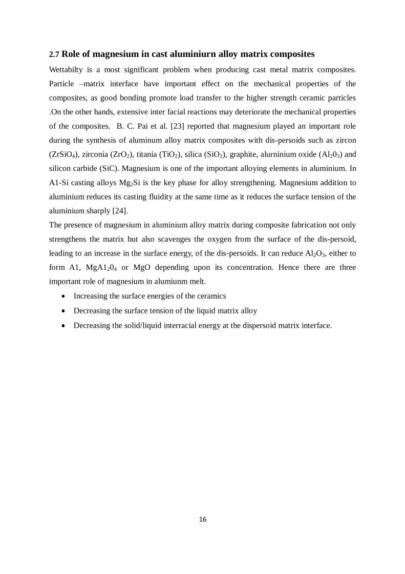
2.7 Role of magnesium in cast aluminiurn alloy matrix composites
Wettabilty is a most significant problem when producing cast metal matrix composites.
Particle –matrix interface have important effect on the mechanical properties of the
composites, as good bonding promote load transfer to the higher strength ceramic particles
.On the other hands, extensive inter facial reactions may deteriorate the mechanical properties
of the composites. B. C. Pai et al. [23] reported that magnesium played an important role
during the synthesis of aluminum alloy matrix composites with dis-persoids such as zircon
(ZrSiO4), zirconia (ZrO2), titania (TiO2), silica (SiO2), graphite, alurninium oxide (Al203) and
silicon carbide (SiC). Magnesium is one of the important alloying elements in aluminium. In
A1-Si casting alloys Mg2Si is the key phase for alloy strengthening. Magnesium addition to
aluminium reduces its casting fluidity at the same time as it reduces the surface tension of the
aluminium sharply [24].
The presence of magnesium in aluminium alloy matrix during composite fabrication not only
strengthens the matrix but also scavenges the oxygen from the surface of the dis-persoid,
leading to an increase in the surface energy, of the dis-persoids. It can reduce Al2O3, either to
form A1, MgA1204 or MgO depending upon its concentration. Hence there are three
important role of magnesium in alumiunm melt.
Increasing the surface energies of the ceramics
Decreasing the surface tension of the liquid matrix alloy
Decreasing the solid/liquid interracial energy at the dispersoid matrix interface.

17
2.8 Particulate reinforced metal matrix composites
The other tendency in the research of Al matrix composites is to develop more inexpensive
production techniques especially for discontinuously reinforced MMCs. The large
consumption of monolithic aluminium alloys has enabled the development of production
technology to very efficient and reliable level. Many of these technologies can be applied to
production of aluminium matrix composites as well. For instance, standard shaping methods,
such as extrusion, forging and rolling, can be used. Traditionally, liquid state processes [25-
26, 6], such as various casting methods, and powder metallurgical methods are used in
production of particulate reinforced Al matrix composites. However, new deposition and in
situ processes are potentially very efficient and economical and, therefore, they are actively
studied. Powder metallurgical route is difficult to be automated and, thus it is very probably
not the right answer for economical production of A1 matrix composites. Hence, the most
promising processes are found among on the liquid state, deposition and in situ processes.
The most simple, inexpensive and widely used methods for monolithic Al parts are various
casting techniques. It is therefore natural that a lot of emphasize is put on developing these
techniques for Al matrix composites as well. In order to ensure homogenizes distribution of
reinforcement particles in the matrix metal stirring my using mechanical, electromagnetic or
gas mixing is necessary. Especially, semi-solid slurry mixing methods, such as compocasting
or rheocasting [27], have gathered increasing interest. Because of the high viscosity of the
slurry higher volume fractions of reinforcement can be processed than in normal casting and
the particles are more homogeneously distributed as well. It is even possible to use non-
wetting particles, which are entrapped in the slurry. Moreover, the reactions between the
matrix and reinforcements are reduced.
The SiC particles are the most common discontinuous reinforcements in Al matrix
composites although the density of SiC is slightly higher than that of Al. This is because it is
inexpensive and readily available but still gives the composite high strength and elastic
modulus. The improved wear resistance is often the primary feature as well. In the same way
as in the case of continuous SiC fibres the possibility of chemical reactions limits the high
temperature applications and may cause problems in production. Excess Si reduces the
reactivity of SiC in A1 remarkably. Another widely used particulate reinforcement in Al
matrix composites is Al203. In comparison to SiC it is much more inert in Al and it is also
oxidation resistant. Accordingly, it is much more suitable for high temperature fabrication and
use. In order to overcome the problem of poor wettability of A1203 by A1, which disturbs

18
especially the liquid stirring production routes, the matrix is alloyed or the reinforcement is
surface coated. As described previously, Li is found to be a beneficial alloying element. MgO
on the surfaces of A1203 is also improving the wettability. On the other hand, in squeeze
casting the wettability is not as large problem as in liquid stirring. Therefore, this efficient
technique has been often utilized in production of particulate A1203 reinforced Al matrix
composites. In fact, this combination of production method and composite material Al is
currently the most promising candidate for large scale production of relatively inexpensive
MMCs for general Al applications. In the early stage of development of the cast particulate
composite, the particles are injected in molten Al through carrier gas[28], to achieve greater
recovery, the coating of the particles has been suggested than the uncoated one e.g. Nickel
coating with graphite particles in case of Al matrix composites. Ni improves the wettability of
the particle by Al melt. Not only Ni but also the addition of Mg, Li, Si Ca, in Al melt
improves wettabi1ity either by changing the interface energy through some interracial
reaction or by modifying the oxide layers in the metal surface Detailed investigation of Pai et
al. and P.K.Rohatgi [6] and co workers have observed that magnesium increases the
wettability of the fly ash in the Al melt. In a recent study it has been demonstrated that the
addition of Ca improves the wettability of Al 4.5% eu melt by its effects on improvement of
retention of particles is less that with Mg addition. To ensure the uniform distribution of
particles, stirring of the melt are suggested.
To ensure the uniform distribution of particles, stirring of the melt are suggested. Pellet
methods are developed to incorporate ceramic particles into Al melt by Pai and Mc Donald
and co workers [29, 30]. In this method the coarser particles of base alloy and reinforcing
ceramic particles are mixed and pressed to form pellets. These pellets were subsequently
plunged into the melt followed by slow stirring manually or mechanically. But the
distribution of particles of the cast particulate composite was not satisfactory uniform when it
is prepared by injection technique or pallet method without stirring. To over come such
difficulty Vortex method was developed [19, 31]. This the most common method used at
present for cast metal matrix particulate composite. In this method molten metal in a crucible
is stirred with a available impeller to form a vortex in the melt. Required amount of ceramic
particles are added into the vortex at a predetermined rate. The particles get entrapped in the
melt and distribute uniformly in it during stirring. The development of SiO2 coating on fly
ash particles is demonstrated as an effective way to improve matrix-reinforcement bonding
during the manufacturing by a liquid route of Al matrix composite [32].

19
Heat treatment of the particles before dispersion into the melt aids their transfer by causing
desorption of adsorbed gases from the particle surface. Heating silicon carbide particles to
9008C, for example, assists in removing surface impurities and in the desorption of gases,
and alters the surface composition by forming an oxide layer on the surface[33].The addition
of pre-heated alumina particles in Al-Mg melt has been found to improve the wetting of
alumina [34]. A clean surface provides a better opportunity for melt-particles interaction, and
thus, enhances wetting. Ultrasonic techniques, various etching techniques, and heating in a
suitable atmosphere can be used to clean the particle surface. Ultrasonic vibration has been
applied to molten aluminium in order to improve the wettability of alumina particles [35].
S. Sarkar and S. C. panigrahi have worked on the Effect of Particle Distribution on the
properties of Aluminum Matrix In-situ Particulate Composites [36] and conclude that
discontinuously reinforced aluminum matrix composites are fast emerging materials that
compete with conventional metallic materials. In-situ particulate composites in comparison
with conventional cast particulate composites produced by external addition, promote cleaner
interfaces, eliminate interface incompatibility of the matrices with the reinforcements, help to
achieve greater thermodynamic stability of reinforcement particles in the matrix at elevated
temperature, and also increase the possibility of developing coherency between the matrix
and particles formed in-situ. The morphology and the distribution of particles strongly
influence the physical and mechanical properties of the composites. In the present study,
illuminate was added to molten aluminum, aluminum–magnesium and aluminum–silicon
alloys by vortex method. The oxides present in ilumenite are observed to react with
aluminum, magnesium and resulting in production of Al2O3, MgO and metallic Fe and Ti,
which dissolved in liquid aluminum. The strength and hardness value showed considerable
improvement. The resulting composites also show appreciable ductility

20
2.9 Aluminium -fly ash particulate reinforced composite
M. Ramachandra K. Radhakrishna [37] has worked on the Effect of reinforcement of fly ash
on sliding wear, slurry erosive wear and corrosive behavior of aluminium matrix composite.
Al (12 wt% Si) as matrix material and up to 15 wt% of fly ash particulate composite was
fabricated using the stir casting rote and came forward into following conclusions
Fly ash improves abrasive wear resistance (20-30%) of Al. and reduces the coefficient
of friction.
Increase in normal load and sliding velocity increases magnitude of wear and
frictional force.
Different wear mechanisms were studied under varying different parameter such as
normal load, % of fly ash content and sliding velocity. Four different mechanisms are
found that are abrasion, oxidation, delamination, thermal softening and adhesion.
Corrosion resistance of reinforced composite has decreased with increase in flyash
content.
Sudarshan, M.K. Surappa [38, 39] have synthesized A356 Al–fly ash particle composites
.They studied mechanical properties and dry sliding wear and come into brief idea that
Fly ash with narrow size range (53–106µm) show better properties compared with
the wider size range (0.5–400µm) particles.
The damping capacity of composite increases with the increase in volume fraction of
fly ash.
Fracture surface of composites show mixed mode (ductile and brittle) fracture.
The 6% of fly ash particles into A356 Al alloy shows low wear rates at low loads (10
and 20 N) while 12% of fly ash reinforced composites show lower wear rates
compared to the unreinforced alloy in the load range 20–80 N.
The types of wear dominant in unreinforced alloy are adhesive wear, whereas abrasive
wear is predominant in composites. At higher load, subsurface delamination is the
main mechanism in both the alloy as well in composites.
R.Q. Guoa and P.K. Rohatgi, while studding the changes of chemical reaction between the Al
and the fly ash during synthesis or reheating [40] of fly ash found out that
The chemical reactions do occur between the fly ash an Al melts. The SiO2and Fe2O3
present in the fly ash is reduced to Si and Fe .The melt oxidized to Al2O3.

21
The above mentioned reactions do occur rapidly at the temperature more than 8500C
.At this higher temperature the free energy of transformation has significant negative
value to occur this reaction spontaneously.
The reaction between Al and fly ash complete after10 hours
P. K. Rohatgia, J. K. Kima, [41] and co workers have worked on Compressive characteristics
of A356/fly ash cenosphere composites synthesized by pressure infiltration technique and
conlude that
Using gas pressure infiltration up to 20 to 65% volume percentage of fly ash can be
reinforced.
The various factors affecting the densities of the composites melt temperature, applied
pressure, and the size of particles.
P. K. Rohatgi, N. Gupta, and Somon Alaraj [42] have studied the coefficient of thermal
expansion of pure Al containing 65 vol% of hollow fly ash particles and suggested that
Composites with a lower coefficient of thermal expansion can be made by
incorporating cenospheres under controlling the processing parameter for a given
volume fraction of reinforcement.
Composite synthesized at different pressure for different infiltration time (min) and
came to conclude tha increase in the infiltration pressure and temperature improves
the infiltration and decreases the entrapped air voids, as a result of which lower the
coefficient of thermal expansion.
J. Sobczak, J. Bienias and co workers [43] have synthesized fly ash particles as reinforcement in
metal matrix composites by squeeze casting technology and gravity casting and compared
between them and have come to following conclusion
Squeeze casting technology is much useful in comparison with gravity casting.
Because it has structural homogeneity with less porosity and good interracial bonding.
Due to presence of fly ash particle in the composite the corrosion is pitting type
corrosion.
S. Sarkar, S. sen and S. C. Mishra and co workers has studied on Aluminum – fly ash
composite produced by impeller mixing[7] and came into a brief idea that
Up to 17wt% fly ash reinforcement can be reinforced by liquid metallurgy route.

22
The addition of magnesium into the alumium melt increase the wettabilty and thus
increase in the mechanical properties such as hardness, tensile strength and the wear
resistance is observed.
P.K. Rohatgi, D. Weiss, and Nikhil Gupta [44] in this paper studied that al- fly composite can
be used for automotive and other applications and show details on environmental and energy
benefits.
The potential cost, energy, and pollution savings as a result of incorporation of fly ash
in aluminum is huge.
The potential reduction in cost and energy content of individual auto parts, energy
consumption, and emissions due to the replacement of 20% aluminum by fly ash
show the substantial benefit of using ALFA composites.

23
2.10 FLY ASH
Fly ash is one of the residues generated in the combustion of coal. It is an industrial
byproduct recovered from the flue gas of coal burning electric power plants. Depending upon
the source and makeup of the coal being burned, the components of the fly ash produced vary
considerably, but all fly ash includes substantial amounts of silica (silicon dioxide, SiO2)
(both amorphous and crystalline) and lime (calcium oxide, CaO). In general, fly ash consists
of SiO2, Al2O3, and Fe2O3 as major constituents and oxides of Mg, Ca, Na, K etc. as minor
constituent. Fly ash particles are mostly spherical in shape and range from less than 1 μm to
100 μm with a specific surface area, typically between 250 and 600m2/kg. The specific
gravity of fly ash vary in the range of 0.6-2.8 gm/cc. Coal fly ash has many uses including as
a cement additive, in masonry blocks, as a concrete admixture, as a material in lightweight
alloys, as a concrete aggregate, in flow able fill materials, in roadway/runway construction, in
structural fill materials, as roofing granules, and in grouting. The largest application of fly ash
is in the cement and concrete industry, though, creative new uses for fly ash are being
actively sought like use of fly ash for the fabrication of MMCs.
2.10.1Classification on the basis of Chemical Composition:
Fly ash is a pozzolanic material and has been classified into two classes, F and C, based on
the chemical composition of the fly ash. According to ASTM C 618, the chemical
requirements to classify any fly ash are shown in Table 2.10.1.
Table 2.10.1Chemical Requirements for Fly Ash Classification
Properties Class F Class C
Silicon dioxide (SiO2) plus aluminum oxide
(Al2O3) plus iron oxide (Fe2O3), min, %
70.0 50.0
Sulfur trioxide (SO3), max, % 5.0 5.0
Moisture Content, max, % 3.0 3.0
Loss on ignition, max, % 6.0* 6.0
2.11.2 On basis of size, shape and structure:
1. Precipitator fly ash

24
It is spherical in nature, the spheres are solid and the density is in the range of 2.0–2.5 g cm-3.
2. Cenosphere fly ash
It is also spherical in shape but these spheres are hollow, so the density of this kind of fly ash
is very less as compared to the precipitator fly ash. Here density is less than 1 gm cm-3 (0.3-
0.6gm/cc)
2.11 WHY FLY ASH
1. The preference to use fly ash as a filler or reinforcement in metal and polymer matrices is
that fly ash is a byproduct of coal combustion, available in very large quantities at very low
costs since much of this is currently land filled. Currently, the use of manufactured glass
micro spheres has limited applications due mainly to their high cost of production. Therefore,
the material costs of composites can be reduced significantly by incorporating fly ash into the
matrices of polymers and metallic alloys. However, very little information is available on to
aid in the design of composite materials, even though attempts have been made to incorporate
fly ash in both polymer and metal matrices. Cenosphere fly ash has a lower density than talc
and calcium carbonate, but slightly higher than hollow glass. The cost of cenosphere is likely
to be much lower than hollow glass .Cenosphere may turn out to be one of the lowest cost
fillers in terms of the cost per volume.
2. The high electrical resistivity, low thermal conductivity and low density of fly-ash may be
helpful for making a light weight insulating composites.
3. Fly ash as a filler in Al casting reduces cost, decreases density and increase hardness,
stiffness, wear and abrasion resistance. It also improves the maintainability, damping
capacity, coefficient of friction etc. which are needed in various industries like automotive
etc.
4. As the production of Al is reduced by the utilization of fly ash. This reduces the generation
of green house gases as they are produced during the bauxite processing and alumina
reduction.

25
2.12Chemical reaction between al and fly ash
The thermodynamic analysis indicates that there is possibility between the reaction of Al melt
and the fly ash particles. The particles contain alumina, silica and iron oxide which during
solidification process of Al fly ash composites or during holding such composites at
temperature above 8500 C, are likely to undergo chemical reactions, reported by
P.K.Rohatagi and Guo. The experiments indicate that there is a progressive reduction
between SiO2, Fe2O3 and mullite by Al and formation of Al2O3, Fe and Si. The wall of
cenosphere fly ash particles progressive disintegrates into discrete particles into the reaction
progress.

26
2.13 Wear behavior
Wear behavior is the surface damage or removal of material from one or both of two solid
surfaces in a sliding, rolling, or impact motions relative to one another. So it is surface
phenomenon that occurs by displacements and detachments of materials. Wear problems
generally differ from those entailing outright breakage, as wear usually a progressive loss of
weight and alterations of dimensions over a periods of time.
Wear is undesirable products in almost all machine applications such as bearings seals gears,
and cams etc. Wear of those components may range forms mild polishing type attrition to
rapid and severe removal of material accommodating with surface roughing. W heather or not
wear constitutes failure of these components depends upon whether the wear deleteriously
affects the ability of the components to function. Even mild polishing type ear of a close
fitting pool in a hydraulic vale may cause excessive leakage and thus constitute failure, even
though the surface of the pool is smooth and apparently undamaged .On the other hand, a
hammer in rock crusher can continue to function satisfactorily in spite of serve detecting,
gouging and removal of as much as several inches of surface metal.
Laws of wear
The laws governing wear are not completely clear but both adhesive and abrasive wear a
simple equation can be written as:
V/X = K*(W/H)
Where,
V=Wear volume
X=Sliding distance
W=Normal load applied
H=Initial hardness of the softer sliding components
K= Wear coefficients
Further it has also been shown that there is relation between hardness H of the metal and its
yield or flow pressure σy which given by:
H= 3* σy
From these equations we can conclude that the total volume of the metal removed due to
sliding is directly proportional to applied loads, sliding distance and inversly proportional to
hardness of the softer sliding component.

27
2.12.1Types of wear
Wear has been categorized in various ways. The phenomenological approach is based on a
macroscopic description of appearance of the worn surface. For that is suffering, rubbing
fitting. But his system has its limitations as it goes not focus on his mechanism of wear and
therefore must relay almost entirely on imperial solutions to wear problems.
Another way is to categorize wear ways on the fundamental mechanism that operating but
this approach is complicated by the fact that more than one mechanism may be operating at a
time and by the lack of sufficient information .A third type of classification describes wear
based on the shape and size of the wear debris particles generated.
A potential wear situ tons exists whenever there is a relative motion between two solids under
loads. Broadly speaking the motion can be unit directional or reciprocating either sliding or
rolling .There may be a combination of rolling and sliding are wear may occur due to
oscillatory movement at small amplitudes metal can interact with non metal or liquids such as
lubricating or marine water.
Depending on the nature of movement of the media following types wear has been classified.
Abrasive wear
Adhesive wear
Corrosion wear
Erosive wear
Fatigue wear
Fretting
Abrasive wear
Abrasive wear occurs when asperities of rough, hard surface or hard particles slide on a softer
surface and damage the interface by plastic deformation or fracture. In case of ductile
materials with high fracture toughness, hard asperities or hard particles result in the plastic
flow of the softer material. Most metallic and ceramic surfaces during sliding show clear
evidence of plastic flow, even some ceramic brittle materials. In one way abrasive wear is
classified as gouging abrasion, high stress (grinding) abrasion. In` gouging, abrasion large
particles are removed from surface, leaving dip groves and/or pits .High stress or grinding
abrasion is accompanied by fracture of the abrasive particles. Low stress or scratching
abrasion occurs when the loads is low enough that the abrasive particles are not fracture.
Another way of classification divides abrasion into two bodies or three body abrasion. In the
first case the hard surface is the harder of two rubbing surface (two body abrasion), for

28
example, in mechanical operations such as grinding, cutting and machining. In three body
abrasion; the hard surface is a third body generally a small particle of abrasive, caught
between the two surfaces and sufficiently harder that is able to abrade either one or both
mating surfaces, for examples, in free-abrasive lapping and polishing.
Adhesive wear
Adhesive wear occurs when two nominally flat bodies are in sliding contact, whether
lubricated or not. Adhesion (or bonding) occurs at the asperity contacts at the interface, and
these contacts are shared by sliding which may result in detachment of a fragment from one
surface and attachment to the other surface .As the sliding continues the transferred fragment
may come off the surface on which they are transferred and be transferred back to original
surface ,or else from loses wear particles .Some are fractured by fatigue process during
repeated loading and unloading action resulting in the form of lose particles.
Corrosive wear
Wear where contribution to the wear rate by the chemical reaction with the environment .In
certain cases chemical reaction is followed by removal of the corrosion product by
mechanical action that is abrasion .It may be occur that the mechanical action precedes the
chemical action and results in he formation of very small particles of debris, which
subsequently react with environment. Due to the chemical reaction change the corrosion by
reaction with environment.
Erosive wear
This type of wear results when grits impinge on solids while cavitations erosion may arise
when a components rotates in a medium .Erosion of surface can take place in a liquid
medium,even without the presence of solid abrasive in that medium. Cavitations involve
formation and subsequent collision of bubbles within the liquids .The collision of liquid
droplets with the solid surface at high speed results in form of liquid erosion called liquid
impingement. It involves the progressive removal of materials from surfaces by repeated
impulse loading at microscopically small areas.
Fatigue wear
Fatigue wear arises as a result of cyclic loadings for examples in rolling elements bearings
lose of materials occurs by spelling of surface layers .It may be due to failure of lubricated
contacts as in gears, friction drives and ball and roller bearings. The fatigue cracks are
believed starts below the surface at a point where the shear stress is maximum so improve

29
the components .Working is done at low contacts loads and having an optimum depth of hard
cases coupled with a high degree of surface finish .
Fretting
Fretting occurs where low amplitude oscillatory motion in tangential direction takes place
between contacting surfaces, which are nominally at rest. This is a common occurrence
science most machinery is subjected to vibration, both in transit and in operation .Basically,
fretting is a form of adhesive or abrasive wear where the normal load causes adhesion
between asperities and oscillatory movement causes rupture resulting in wear debris.
Fretting may be of two type; One is contact collision that takes place between the bore of
bearings and the shaft or between the out side surface of bearing contact and bore housing.
Another type is fretting damage within bearing contact area .This type of fretting is
frequently reffed as false braining.

30
CHAPTER-3
3. EXPERIMENTAL WORK
3.1 Raw materials
The matrix material used in the experiment investigation was commercially pure
aluminium.The fly ash was collected from RSP steel pant Orissa, India. The particle size of
the fly as received condition lies in the range from (0.1-100 μm).
3.2 Melting and casting
The aluminum fly ash metal matrix composite was prepared by stir casting route. For this we
took 500gm of commercially pure aluminum and desired amount of fly ash particles. The fly
ash particle was preheated to 3000C for three hour to remove moisture. Commercially pure
aluminum was melted in a resistance furnace. The melt temperature was raised up to 7200C
and it was degassed by purging hexa chloroethane tablets. Then the melt was stirred with the
help of a mild steel turbine stirrer. The stirring was maintained between 5 to 7 min at an
impeller speed of 200 rpm .The melt temperature was maintained 7000C during addition of
fly ash particles. The dispersion of fly ash particles were achieved by the vortex method. The
melt with reinforced particulates were poured into the preheated permanent metalic mold.
The pouring temperature was maintained at 6800C.The melt was then allow to solidify the
moulds. The composites were made with a different amount of fly-ash (i.e.5, 10, 20, wt %),
Magnesium and silicon were added to increase the wettability of fly ash particles.

31
Fig 3.1.Laboratory stir casting set up
3.3 Microstructural characterization.
3.3.1 Scanning electron microscopy
Micro structural characterization studies were conducted on unreinforced and reinforced
samples. This is accomplished by using scanning electron microscope. The composite
samples were metallographically polished prior to examination. Characterization is done in
etched conditions. Etching was accomplished using Keller‘s reagent. The SEM micrographs
of composite and wear debris were obtained using the scanning electron microscope. The
images were taken in both secondary electron (SE) and back scattered electron (BSE) mode
according to requirement. Microscopic studies to examine the morphology, particle size and
micro structure were done by a JEOL 6480 LV scanning electron microscope (SEM)
equipped with an energy dispersive X-ray (EDX) detector of Oxford data reference system.
Micrographs are taken at suitable accelerating voltages for the best possible resolution using
the secondary electron imaging.

32
Fig 3.2: JEOL JSM-6480LV scanning electron microscop
3.3.2 Optical microscopy
The casting procedure was examined under the optical microscope to determine the casr
structure .A section was cut from the castings. It is first belt grinded followed by polishing
with different grade of emery papers. Then they were washed and polished in clothes and
then washed, dried and etched with Keller‘s solution and then examined though optical
microscope.
3.4 Particle size analysis
Particle size of the milled powder was measured by Malvern particle size analyzer (Model
Micro-P, range 0.05-550 micron). Firstly, the liquid dispersant containing 500 ml of distilled
water was kept in the sample holder. Then the instrument was run keeping ultrasonic
displacement at 10.00 micron and pump speed 1800 rpm.

33
Figure 3.3: Malvern particle size analyzer (Model Micro-P, range 0.05-550 micron).
3.5 Mechanical properties observation.
3.4.1 Hardness
Bulk hardness measurements were carried out on the base metal and composite samples by
using standard Brinnel hardness test. Brinnel hardness measurements were carried out in
order to investigate the influence of particulate weight fraction on the matrix hardness. Load
applied was 750kgs and indenter was a steel ball of 5 mm diameter.
3.4.1 Tensile test
The tensile testing of the composite was done, on Instron testing machine. The sample rate
was 9.103pts/sec and cross-head speed 5.0 mm/min. Standard specimens with 30mm guge
length were used to evaluate ultimate tensile strength. The comparison of the properties of the
composite material was made with the commercially pure Al.

34
3.6 Sliding wear behavior
Wear has been defined as the displacement of material caused by hard particles or hard
protuberances where these hard particles are forced against and moving along a solid surface.
Two body sliding wear tests were carried out on prepared composite specimens. A Ducom,
Bangalore makes computerized pinion- disc wear test machine was used for these tests. The
wear testing was carried out at a constant sliding velocity of 1m/sec with normal loads of
10N, 15N, 20N. A cylindrical pin of size 1.1cm diameter and 2.1cm length prepared from
composite casting was loaded through a vertical specimen holder against horizontal rotating
disc. Before testing, the flat surface of the specimens was abraded by using 2000 grit paper.
The rotating disc was made of carbon steel of diameter 50 mm and hardness of 64 HRC.
Wear tests were carried out at room temperature without lubrication for 30 min. The principal
objective of investigation was to study the coefficient of friction and wear.
3.7 Worn surface and debris examination
The debris and worn surface wear pin were studied under SEM and optical microscope.

35
CHAPTER-4
4. Results and discussions
4.1 Fly ash analysis
Table 4.1Composition of fly ash used as reinforcement in wt%
Compounds Percentages (%)
SiO2 67.2
Al2O3 29.6
Fe2O3 0.1
CaO 1.4
MgO 1.7
Fig 4.1SEM Micrograph of fly ash used in the study.

36
Fig.4.2- Particle size analysis of fly ash
Fly ash from Rourkel steel plant (India) had a wide particle size distribution. The particle size
of the fly as received condition, lies in the range from (0.1-100 μm).The SEM micro-graph of
the fly ash is shown in fig4.1. The major components of fly ash as received from the source
and used for reinforcement are listed in Table 4.1 in wt%. The fly ash consist mainly Al2O3
(29.6 wt %) and SiO2 (67.2wt %).

37
4.2. Optical microstructure of cast composites
Fig.4.3- Al+ 5% fly ash composite . Fig4.4- Al+ 10% fly ash composite
Fig.4.5-Al+15% fly ash composite Fig.4.6-Al+20% fly ash composite
50X 50X
50X 50X

38
Fig.4.7-Al+2%Si+10% fly ash composite Fig.4.8- Al+2%Mg+10% fly ash composite
50X 50X

39
4.3. SEM micrographs of the MMCs
Fig.4.9- Al+ 5% fly ash composite Fig.4.10-Al+ 10% fly ash composite
Fig.4.11-Al+15% fly ash composite Fig.4.12-Al+ 20% fly ash composite

40
Fig.4.13- Al+2%Si+10% fly ash composite Fig.4.14-Al+2%Mg+10% fly ash composite
The SEM micrographs of Al-fly ash composites are shown in fig 4.8 to 4.14.
The size, density, type of reinforcing particles, and its distribution have a pronounced effect
on the properties of particulate composites. The variables affecting the distribution of
particles are solidification rate, fluidity, type of reinforcement, and the method of
incorporation. It is essential to get particles uniformly throughout the casting during
particulate composite production. The first task is to get a uniform distribution of particles in
the liquid melt and then to prevent segregation/agglomeration of particles during pouring and
progress of solidification. One of the major requirements for uniform distribution of particles
in the melt is its wettability.

41
4.4. Distribution of particles in MMCs
Fig 4.15(a) Different locations of selected sample
Al-10% Fly ash composite
Al+2%Si+10%Fly ash
Al+2%Mg+10%Fly ash
Fig.4.15 (b) Macrographs showing distribution of particles

42
The micro structure of the samples, cut from the plate casting at different locations, were
observed to study the particle distribution(fig 4.15.a )In the case of Al–10% Fly ash, particles
were not uniformly distributed throughout the casting. The particles were segregated at the
top, bottom, and sides of the plates. The interior of the casting contained very few particles,
whereas in the case of Al–2% Mg–10% fly ash and Al–2% Si–10% fly ash particles were
present more or less throughout the casting. The particle distribution strongly influences the
density of composites. Thus, the density distribution can be used as a measure of particle
distribution. In case of Al–10% fly ash, particle rejection was also high. Figure 4.15.b shows
schematically the particle distribution in the cast plates.

43
4.5. Mechanical properties of cast composites
Table 4.2 Hardness
Sl No. Samples Designation Hardness
(BHN)
1 As cast Al 58.31
2 Al+10%fly ash 67.05
3 Al+2%Si+10%fly ash 70.09
4 Al+2%Mg+10%fly ash 85.95
Fig.4.16- Graph showing variation in hardness with composition of MMCs
The above table shows that incorporation of fly ash particles in Aluminum matrix causes
reasonable increase in hardness. The strengthening of the composite can be due to dispersion
strengthening as well as due to particle reinforcement. Thus, fly ash as filler in Al casting
reduces cost, decreases density and increase hardness which are needed in various industries
like automotive etc.

44
Table 4.3.Tensile properties composites
This indicates that the fly ash addition leads to improvement in the ultimate tensile strength.
Form the table it is clear that addition of Mg improve the tensile properties of the composite.
The size range of the particles is very wide. The size ranges of the fly ash particles
indicate that the composite prepared can be considered as dispersion strengthened as well as
particle reinforced composite. As is seen from the particle size distribution there are very fine
particles as well as coarse ones (1-100 μm). Thus the strengthening of composite can be due
to dispersion strengthening as well as due to particle reinforcement. Dispersion strengthening
is due to the incorporation of very fine particles, which help to restrict the movement of
dislocations, whereas in particle strengthening, load sharing is the mechanism.
Sl No. Samples Designation Hardness (BHN) U.T.S
(Mpa)
%
Elongation
2 Al+10%fly ash 67.05 129 4
3 Al+2%Si+10%fly ash 70.09 145 3
4 Al+2%Mg+10%fly ash 85.95 159 2

45
4.6. Wear behavior
Wear behavior of different composite was studied with different parameter like sliding
velocity and applied loads. There result and discussion are given in the following subsections.
4.6.1. Effect of sliding distance
For the entire composites the sliding velocity is 1m/sec and the total running time is 30min
with a constant load of 10N.
Pure Aluminum Al+2%Si+10%fly ash
Al+10%fly ash Al+2%Mg+10%fly ash
Fig.4.17-Wear behavior of MMCs with different composition under normal load of 10N
Figs. 4.17, 4.18 and4.19 show of wear curves of MMCs specimen with 10% fly ash, 2%
10% fly ash with 2% Si and 10% fly ash with 2% Mg content with normal load of 10N, 15N,
20N. All the MMCs showed a very small initial nonlinear wear regime. After a certain sliding
distance, the wear has increased linearly with time indicating steady state wear regime. The
transition from initial wear regime to steady state regime has taken place with in few minutes
(2–3 min) of commencement of the test From the graph (Fig.4.17) it is evident that the wear
resistance of composite is much greater than the commercially pure aluminium .Bulk wear
decrease with addition of magnesium. Incorporation of fly ash content significantly reduces
wear. This evidence from the amount of wear observed for commercially pure aluminum and
composite with 2% Mg +10%fly ash content. This is because of the presence of hard fly ash
particle which will increase over all bulk hardness.

46
Al+10%fly ash Al+2%Si+10%fly ash
Al+2%Mg+10%fly ash
Fig.4.18-.Wear behavior of MMCs with different composition under normal load of 15N
In the initial wear regime, the reinforced particles act as load carrying elements and as
inhibitors against plastic deformation and adhesion of matrix material. In the later stages of
wear regime, the worn particles get dislodged from their positions in the matrix and get
mixed with the wear debris. The wear debris containing matrix material, worn particles and
Fe from the disc get pushed into the craters formed by dislodging of particles and act as load
bearing elements.

47
Al+10%fly ash Al+2%Si+10%fly ash
Al+2%Mg+10%fly ash
Fig.4.19-Wear behavior of MMCs with different composition under normal load of 20N
20N 15N 10N
Fig.4.20- Wear behavior of MMCs with variation in normal load
Fig.4.20. Shows the relation between applied load and wear of the MMCs
(Al+2%Mg+10%fly ash) produced for a particular velocity 1m/sec. The amount of wear has
been increased with increase in normal load.

48
4.6.2. Effect of varition sliding velocity
1m/sec 0.6m/sec 0.2m/sec
Fig.4.21- Variation of behavior of MMCs with variation in sliding velocity
Variation in sliding velocity was achieved by varying rotational speed of the disc with
different rpm keeping track diameter constant .The wear of the composite is significantly
increase with increase in sliding velocity.

49
4.7. Frictional characteristics
Pure Aluminum Al+2%Si+10%fly ash
Al+10%fly ash Al+2%Mg+10%fly ash
Fig.4.22- Variation of coefficient of friction with composition of the composite
The coefficient of friction has been decreased with increased fly ash content as evident from
Fig.4.22.In the test of normal load of 10N and sliding velocity of 1m/sec were used.
Composite (Al+2%Mg+10%fly ash) showed lowest coefficient of friction 0.05and and
commercially pure aluminium exhibited a coefficient of friction range 0.07 to 0.09.The
presence of cenosphere particles will reduce the friction by providing point contact counter
face and pin. The coefficient of friction may have reduced with the increase in cenosphere
particles in fly ash as the presence of cenosphere particles with reduce the friction by
providing point contact between counter face and pin.

50
4.8. Microscopic examination
Optical microscopic examination of the worn pin surfaces identified different wear
mechanism operating under various sliding conditions. In the following sections the observed
wear mechanisms are discussed in relation to the sliding conditions and wear rates for better
understanding of the tribological characteristics.
Fig.4.23-Grooves and scratch marks indicating abrasion wear
Fig.4.24- Deep smooth and large grooves under higher loads
50X
50X
Slide Direction
Wear grooves

51
Fig.4.25- Wear debris filling the valleys in the wear surface
Fig.4.26- Delamination of wear surface under a load of 20N
100X
50X
Delamination
Oxide Debris

52
Abrasion
Most of the grooves are parallel to the sliding direction; it is evident from the worn pins
(fig.4.23). Grooving and scratching appear more severe at the higher loads of 20N and higher
sliding velocity of 1m/sec (Fig. 4.24).Grooves was less severe for lower loads. Such features
are characteristics of abrasion, in which hard asperities of the steel counter face, or hard
reinforced particles in between the contacting surfaces, plough or cut into the pin, causing
wear by the removal of small fragments of material. The abrasion took place primarily via
ploughing, in which material is displaced on either side of the abrasion groove with out being
removed. The abrasion is extensive in Al/fly ash composites tested, due to the presence of
dislodged and fractured fly ash, that become trapped in the sliding interface gets embedded in
the counter face, contributing to abrasive wear. In addition, fractured fly ash particles trapped
between the sliding surfaces would also cause abrasion of the steel disc, as would work-
hardened fragments of matrix alloy and steel.
Oxidation
From optical microscope observation, the dark surfaces are found to be covered extensively
by a thin layer of fine particles. Large amounts of fine powder are also present in the wear
debris. These characteristics are indicative of oxidative wear, in which frictional heating
during sliding causes oxidation of the surface, with wear occurring through the removal of
oxide fragments. Over continuous sliding, oxide wear debris fills out the valleys on the pin
surface, and gets compacted into a protective layer preventing metallic contact and wear rate
of the composite drops accordingly Fig. 4.25.
Delamination
For higher loads of 20N with speed of 1m/sec and the MMCs (Al+2%Mg+10%fly ash), the
wear mechanism has been linked to the process of delaminationin fig 4.26. This is a fatigue-
related wear mechanism in which repeated sliding induces subsurface cracks that gradually
grow and eventually shear to the surface, forming long thin wear sheets. Delamination is
observed to be more extensive under the higher load of 20N.

53
4.9. SEM micrographs of the worn surface the composite
(a)
(b)
Fig.4.27—SEM micrographs of the worn surfaces after the wear test under velocity 1 m/s;
time 30min; (a) load 10N and (b) 20N.
Examination of the worn surfaces of aluminum–fly ash composites under the SEM after wear
test shows that under the load of 10N, the worn surface has relatively less ploughing and
cutting, as shown in Figure 4.27(a). However, at the load of 20N, fractured fly ash particles
are frequently present on the worn surface, as shown in Figure 4.27 (b).

54
4.10. Wear debris
(a)
(b)
Fig.4.28-SEM micrographs of debris of the MMCs at different loads at (a) 10N, (b) 15Nand
(c) 20N

55
The material is transferred back and forth several times during the sliding process and
eventually produces particles of wear debris. When the applied load results in stresses higher
than the fracture stress of fly ash particles, these particles loose their ability to support the
load. Consequently, the aluminium matrix comes in direct contact with the counter face and
large plastic strains are imposed on the contact surfaces of the pin. The severe localized
deformation gives rise to crack formation, a process in which fly ash particle/matrix
decohesion plays an important role. Surface delamination is also contributed to process of
debris formation. Visual observations indicate wear debris are dark in co lour.
A substantial quantity of wear debris was generated during the tests. Two major
morphologies, particle-like or flake- observed in all tests, the only difference is the relative
amount of each type, and this could be influenced to a great degree by the normal load and
sliding velocity. The particle size and irregularity increased with the applied load .The fig
4.27 shows that the size of the particles larger and irregular for 20N applied load as compared
with15N and 10N load. The volume of the wear debris increases with increasing normal
loads and sliding velocity, thereby resulting in greater wear loss for higher loads and sliding
velocities.

56
4.11. Fractograph of the selected composites
.
(a)
Fig4.29-SEM fractograph of Al+2%Mg+10%fly ash
The tensile fracture surface of fly ash reinforced is shown in fig 4.29.The fractograph taken in
SEM revealed absence of dimples which are indicative of ductile fracture. This observation is
consistent with mechanical properties results with show a reduction in elongation. (Table no
4.3).

57
CHAPTER-5
CONCLUSIONS
The flowing conclusion may be drawn form the present work:
From the study it is concluded that we can use fly ash for the production of
composites and can turn industrial waste into industrial wealth. This can also solve the
problem of storage and disposal of fly ash.
Fly ash up-to 20% by weight can be successfully added to commercially pure
aluminum by stir casting route to produce composites.
Addition of magnesium and silicon improves the wettability of fly ash with
aluminium melt and thus increases the retention of the fly ash in the composite.
Hardness of commercially pure aluminium is increased from 58BHN to 86BHN with
addition of fly ash and magnesium.
The Ultimate tensile strength has improved with increase in fly ash content. Where as
ductility has decreased with increase in fly ash content.
The effect of increased reinforcement on the wear behavior of the MMCs is to
increase the wear resistance and reduce the coefficient of friction. The MMCs
exhibited better wear resistance due to its superior load bearing capacity.
The wear resistance of composites is much greater than the commercially pure
aluminium.
Different wear mechanisms were found to operate under the test conditions of
variation of normal loads, composition, and sliding velocity .They are oxidation
abrasion and delamination.
Increased normal load and sliding velocity increases magnitude of wear and frictional
force.

58
CHAPTER-6
References
[1] Mahendra.K.V and Radhakrishna. K, Castable composites and their application in
automobiles, Proc. IMechE Vol. 221 Part D: J. Automobile Engineering, (2007): pp. 135-140
[2] Hung N. P, Boey,F.Y.C. Khor K.A, Phua Y.S. and Lee H.F, Machinability of aluminum
alloys reinforced with siliconcarbide particulates, Journal of Materials Processing
Technology,56 (1996): pp. 966-977
[3] Lindroos V.K, Talvitie M.J, Recent advances in metal matrix composites, J. Mater. Proc.
Technol. 53 (1995): pp. 273–284.
[4] Mohanty Samrat, Chugh Y.P., Development of fly ash-based automotive brake lining,
Tribology International 40 (2007): pp. 1217–1222
[5] Rohatgi P.K,Weiss D, and Gupta Nikhil, Applications of Fly Ash in Synthesizing Low-
Cost MMCs for Automotive and Other Applications, Journal of the Minerals, Metals and
Materials Society, vol 58,(2006): pp 71-76
[6] Rohatgi P.K, Asthana R, Das, S Solidification, structures, and properties of cast metal-
ceramic particle composites, International metals reviews,31(1986): pp. 115-139
[7] Sarkar S., Sen S. and Mishra S. C, Aluminum – fly ash composite produced by impeller
mixing, Journal of reinforced plastics and composites,(2008):pp 1-6
[8] William D. Callister, Jr., Materials Science and Engineering-Materials Science and
Engineering-An Introduction. Asia, John Wiley & Sons, 2001
[9] Hull D, Clyne T W, An Introduction to Composite Materials, Cambridge, UK: Cambridge
Univ. Press, 1996
[10]Matthews F.L., Ralwlings R.D, Composite materials engineering ans science, Glasgow,
UK, Champaman and hall, 1994
[11] Chawla K.K, On the applicability of the "Rule-of-Mixtures" to the strength properties of
metal-matrix composites, Revista Brasileira de Física,4(1974):pp 411-418
[12] Narciso J , Alonso A, Pamies A, Cordovilta C.G, Louis E, Wettability of binary and
ternary alloys of the system Al-Si-Mg with SiC particulates, Scripta Metall. 31 (1994):pp
1495-1500.
[13] Rohatgi P.K, Metal-matrix Composites, Defence Science Journal, Vol 43, No 4, (1993):
pp 323-349
[14] Ibrahim, I.A., Mohamed, F.A., Lavernia, E.J. Journal of Materials Science 26 (5)(
1991):pp. 1137-1156

59
[15] Liu Y. B, Lim S. C, Lu l, Lai M. O, Recent development in the fabrication of metal
matrix-particulate composites using powder metallurgy techniques,journal of materals
science 29 (1994): pp999-2007
[16]Upadhyay G.S, Power metallurgy metal matrix composite:a review of Lanxide‘s
composite technologies,Mat.Sci. & Eng, A 162(1989): pp217-228
[17]Smith P.R, Froes F.H, Development in titanium metal matrix composites, j. Metals,
36(1984): pp 19-26
[18]Ward-close C.M, Partridge P.G, A fiber coating process for advanced metal matrix
composites, j. Mat.Sci 25(1990): pp 4315-4323
[19] Surappa M. K., P. K. Rohatgi, Preparation and properties of cast aluminium-cerarnic
particle composites, journal of materials science, 16 (1981): pp 983-993
[20] J Hashim, Looney L, and Hashmi M.S.J, Metal matrix composites: production by the stir
casting method, Journal of Materials Processing Technology 92-93 (1999): pp 1-7
[21]Mortensen A, Cornie J, On the infiltration of metal matrix composites, Metall. Trans,
18A (1987): pp1160-1163
[22] Banerji Abinash and Reif Winfried, Development of AI-Ti-C grain refiners containing
TiC, 17A (1986): pp 2127-2137
[23] Pai B. C, Geetha Ramani, Pillai R. M, Satyanarayana K. G, Role of magnesium in cast
aluminiurn alloy matrix composites, Journal of materials science 30 (1995):pp 1903-1911
[24] Korolkov A. M., Casting properties of metals and alloys, Consultant Bureau, New York,
(1963): pp. 26, 37
[25] Mehrabian. R, Processing / microstructure relationships in surface melting, Mater. Res.
Soc. Symp, 120 (1983) pp: 733-744
[26] Savage .W. Proc. 2nd Int. Conf on Cast Met. Matrix Composite., IL, USA, (1994): pp.
100
[27] Mehrabian .R. Riek R.G. and Flemings.M.C. Cast composites of aluminum alloys, Met.
Trans. 5 (1974) pp. 1899
[28] Rohatgiand P.K, Badia .F.A, Dispersion of graphite particles in aluminum castings
through injection of the melt, Trans amer foundrymens soc, 77, (1969): pp402-406
[29] Pai B. C, Rohatgi P. K, Production of cast aluminium-graphite particle composites using
a pellet method, Journal of materials science 13 (1978): 329-335
[30]Badia.F.A, McDonland, Graphite Al - A New Method of Production and Some Foundry
Characteristics.Trans Am Foundrymen's Soc Volume 7(1971): pp 630

60
[31] Krishnan B. P, Surappa M. K, Rohatgi P. K, The OPAL process: a direct method of
preparing cast aluminium alloy-graphite particle composites, Journal of materials science 16
(1 981): pp 1209-1 216
[32] Rizam. S.S. Hafizal.Y, Effect of particle coating on matrix-reinforcement bonding,
IcoSM (2007): pp174-177
[33] Agarwala V., D. Dixit, Fabrication of aluminium base composite by foundry technique
Trans. Japan Inst. Met, 22 (1981): pp251.
[34] Pai, Ray B.C.,S. Prabhakar K.V., Rohatgi P.K., Fabrication of Aluminum-Alumina
(Magnesia) Particulate Composites in Foundries Using Magnesium Additions to the Melts,
Mater Sci. Eng, 24(1976): pp 31.
[35] Tsunekawa Y, Nahanishi H, Okumiya M, Mohri N, Application of ultrasonic vibration to
molten aluminum infiltration, Key Eng. Mater. 104-107 (1995): pp 215-224.
[36] Sarkar S Mohan S, Panigrahi S.C, Effect of particle distribution on the properties of
aluminum matrix in-situparticulate composites, Journal of reinforced plastics and composites,
vol. 27(2008):pp 1177-1187
[37] Radhakrishna M. Ramachandra K., Effect of reinforcement of flyash on sliding wear,
slurry erosive wear and corrosive behavior of aluminium matrix composite, Wear 262 (2007):
pp1450–1462
[38]Sudarshan, Surappa M.K., Synthesis of fly ash particle reinforced A356 Alcomposites
and their characterization, Materials Science and Engineering A 480 (2008): pp 117–124
[39] Sudarshan, Surappa M.K. Dry sliding wear of fly ash particle reinforcedA356 Al
composites, Wear 265 (2008): pp 349–360
[40] Guoa R.Q. and Rohatgi P.K. ,Chemical reactions between alumium and fly ash during
synthesis and reheating of Al-fly ash composite,Metallurgical and materials translation B
volume 29B, june (1998): pp 519-525
[41] Rohatgia P. K., J. Kima K., Gupta N., Alaraj Simon, and A. Daoud, Compressive
characteristics of A356/fly ash cenosphere composites synthesized by pressure infiltration
technique, Composites: Part A 37 (2006): pp 430–437
[42] Rohatgi P. K., Gupta N., and Alaraj Somon, Thermal Expansion of Aluminum–Fly Ash
Cenosphere Composites Synthesized by Pressure Infiltration Technique, Journal of
Composite materials, Vol. 40, No. 13(2006) :pp1163-1174

61
[43]J. Bienias, Walczak M., Surowska B., Sobczak J., Microstructure and corrosion
behaviourof aluminum fly ash composites, Journal of Optoelectronics and Advanced
Materials Vol. 5, No. 2, June (2003): pp. 493 – 502.
[44] Rohatgi P.K., Weiss D., and Gupta Nikhil, Applications of fly ash in synthesizing
low-cost mmcs for automotive and other applications,JOM (2006): pp71-76
Top Related