


Languages
Pages
Legal

Structural modelling. Configurations
Lecture 5
Outline
• 5.1. Structural modelling
• 5.2. Generics
• 5.3. Configurations

5.1.Structural modelling
• Structural modelling = when an architecture is modelled as a set of components interconnected by signals.
• The behaviour of the architecture does not result explicitly from the structural description
• Basic statement: – component instantiation statement: - a concurrent
statement
• In the declarative part of the architecture will appear the component declarations
Component declaration
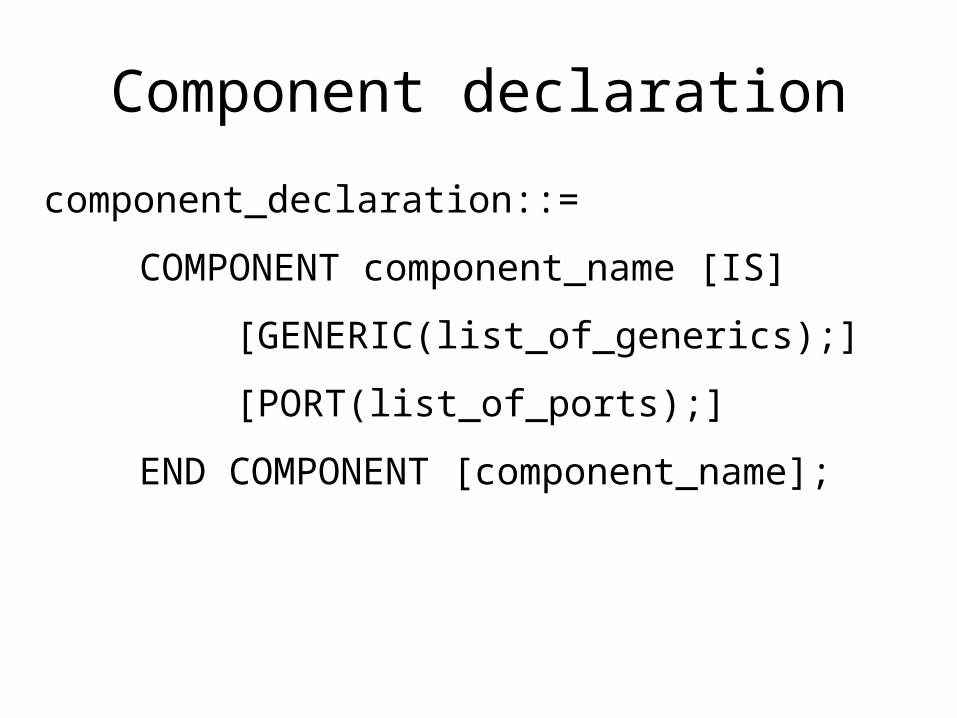
component_declaration::=
COMPONENT component_name [IS]
[GENERIC(list_of_generics);]
[PORT(list_of_ports);]
END COMPONENT [component_name];
Component declaration
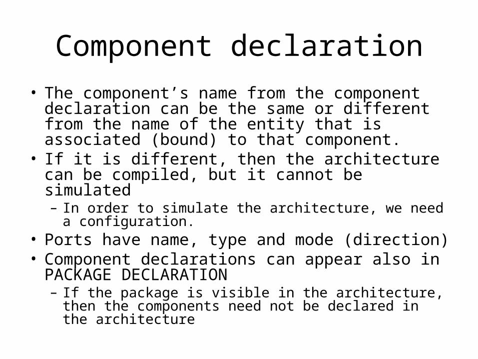
• The component’s name from the component declaration can be the same or different from the name of the entity that is associated (bound) to that component.
• If it is different, then the architecture can be compiled, but it cannot be simulated– In order to simulate the architecture, we need a
configuration.• Ports have name, type and mode (direction)• Component declarations can appear also in
PACKAGE DECLARATION– If the package is visible in the architecture, then the
components need not be declared in the architecture
Component instantiation statement
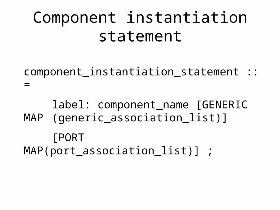
component_instantiation_statement ::=
label: component_name [GENERIC MAP (generic_association_list)]
[PORT MAP(port_association_list)] ;
Component instantiation statement
• Component instantiation statement has a mandatory label:– The label can be any legal identifier and it is
considered the name of the component instantiation
• The component name should be the same like in the component declaration
• The PORT MAP clause makes the association between the formal ports and the actual ports.

Ports• Formal ports are those from the component
declaration• The actual ports can be:
– Ports of the modelled entity– Internal signals.
• For a formal input port, the actual can be an expression (e.g. a value).
• As an actual port can be used the keyword OPEN, which means that the port is not connected– An input port can be OPEN only if it has an initial
value specified at the declaration– A port that is an unconstrained array cannot be OPEN– Any other port may be left unconnected (OPEN).
Ports: mode
• IN: the port can be read, but not written– The IN mode is implicit, i.e., if the mode of a port is
not specified, then it will be considered IN
• OUT: the port can be written, but cannot be read• INOUT: can be both read and written
– An INOUT port may have more than one driver, when it must be a resolved signal.
• BUFFER: can be both read and written– May have a single driver– A formal port BUFFER can be associated an actual
port of mode buffer or an internal signal.

PORT MAP• Associations from the PORT MAP clause
can be:– Positional– Named.
• In positional association– Only the name of the actual port is specified– From its position, it results to which formal
port it is associated– Order of the actuals must coincide with the
order of ports from the component declaration.
PORT MAP
• In the named association:– It is specified name_formal_port => actual_port– Ports’ order is not imporant– Each formal port from the named association is visible only in that
component instantiation statement.
• The positional association can generate errors that are very hard to debug !
• Association rules– 1. The type of the formal and actual port must coincide– 2. If the formal port is readable so must be the actul; if the
formal port is writable so must the actual be.

PORT MAP• The association rules are valid for both types of
association (named and positional).• An internal signal is considered to be both readable and
writable => it may be associated with a formal of any mode, if they have the same type.
• Consequences of the rules:– If an actual port is of mode OUT, it may not be associated to a
formal port of mode IN or INOUT – If an actual port is of mode IN it may not be associated to a
formal port of mode OUT or INOUT.– If an actual port is of mode INOUT it may be associatd to a
forma port of mode IN, OUT or INOUT• Port associations can be made for:
– vectors (e.g. of bits): x(3 DOWNTO 1) => y, where y is BIT_VECTOR(2 DOWNTO 0)
– Or parts of vectors: a(4 downto 1) => b(5 downto 2);

PORT MAP (updated)
• According to 2002 edition of “1076 IEEE Standard VHDL Language Reference Manual”:– For a formal port of mode IN, the actual may be of
mode IN, INOUT or BUFFER– For a formal port of mode OUT, the actual may be of
mode OUT, INOUT or BUFFER– For a formal port of mode INOUT, the actual may be
of mode INOUT or BUFFER– For a formal port of mode BUFFER, the actual may
be of mode OUT, INOUT or BUFFER
Example: the parity generator
V(3)
V(2)
V(1)
V(0)
s1
s2
s3 evenxor1
xor2
xor3
inv1
odd
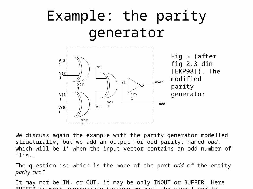
We discuss again the example with the parity generator modelled structurally, but we add an output for odd parity, named odd, which will be 1’ when the input vector contains an odd number of ‘1’s..
The question is: which is the mode of the port odd of the entity parity_circ ?
It may not be IN, or OUT, it may be only INOUT or BUFFER. Here BUFFER is more appropriate because we want the signal odd to have only one driver.
Fig 5 (after fig 2.3 din [EKP98]). The modified parity generator
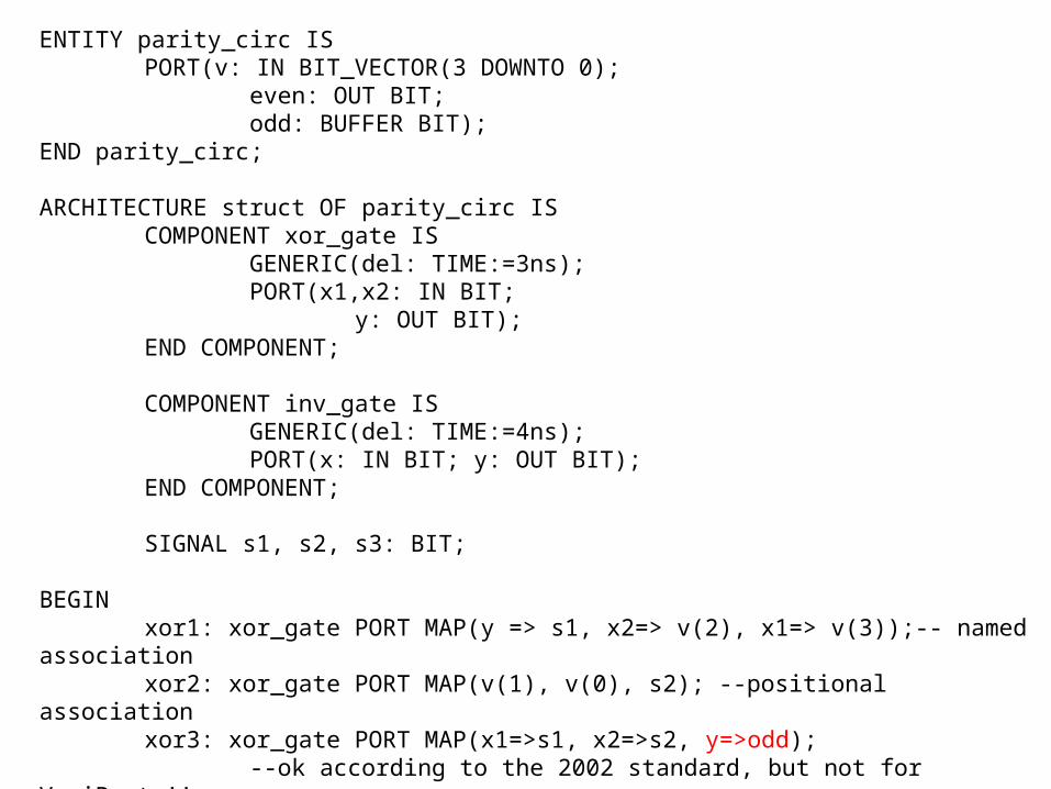
ENTITY parity_circ ISPORT(v: IN BIT_VECTOR(3 DOWNTO 0);
even: OUT BIT;odd: BUFFER BIT);
END parity_circ;
ARCHITECTURE struct OF parity_circ ISCOMPONENT xor_gate IS
GENERIC(del: TIME:=3ns);PORT(x1,x2: IN BIT;
y: OUT BIT);END COMPONENT;
COMPONENT inv_gate IS GENERIC(del: TIME:=4ns);PORT(x: IN BIT; y: OUT BIT);
END COMPONENT;
SIGNAL s1, s2, s3: BIT;
BEGINxor1: xor_gate PORT MAP(y => s1, x2=> v(2), x1=> v(3));-- named associationxor2: xor_gate PORT MAP(v(1), v(0), s2); --positional associationxor3: xor_gate PORT MAP(x1=>s1, x2=>s2, y=>odd);
--ok according to the 2002 standard, but not for VeriBest !!inv1: inv_gate PORT MAP(x=>odd, y=>even);

-- The code accepted by VeriBest:--xor3: xor_gate PORT MAP(x1=>s1, x2=>s2, y=>s3);--inv1: inv_gate PORT MAP(x=>s3, y=>even);--odd<=s3;
END ARCHITECTURE struct;
CONFIGURATION cfg_ parity_circ OF parity_circ ISFOR struct
FOR ALL: xor_gate USE ENTITY WORK.xor2(behave);END FOR;FOR inv1: inv_gate USE ENTITY WORK.inverter(behave);END FOR;
END FOR;END CONFIGURATION;
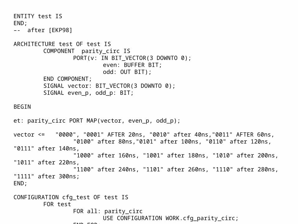
ENTITY test ISEND;–- after [EKP98]
ARCHITECTURE test OF test IS COMPONENT parity_circ IS
PORT(v: IN BIT_VECTOR(3 DOWNTO 0);even: BUFFER BIT;odd: OUT BIT);
END COMPONENT;SIGNAL vector: BIT_VECTOR(3 DOWNTO 0);SIGNAL even_p, odd_p: BIT;
BEGIN
et: parity_circ PORT MAP(vector, even_p, odd_p);
vector <= "0000", "0001" AFTER 20ns, "0010" after 40ns,"0011" AFTER 60ns,"0100" after 80ns,"0101" after 100ns, "0110" after 120ns, "0111" after 140ns,"1000" after 160ns, "1001" after 180ns, "1010" after 200ns, "1011" after 220ns,"1100" after 240ns, "1101" after 260ns, "1110" after 280ns, "1111" after 300ns;
END;
CONFIGURATION cfg_test OF test ISFOR test
FOR all: parity_circUSE CONFIGURATION WORK.cfg_parity_circ;
END FOR;END FOR;
END CONFIGURATION;
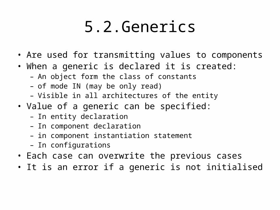
5.2.Generics
• Are used for transmitting values to components• When a generic is declared it is created:
– An object form the class of constants– of mode IN (may be only read)– Visible in all architectures of the entity
• Value of a generic can be specified:– In entity declaration– In component declaration – in component instantiation statement– In configurations
• Each case can overwrite the previous cases• It is an error if a generic is not initialised
Generics
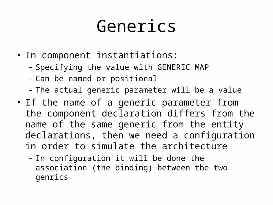
• In component instantiations: – Specifying the value with GENERIC MAP
– Can be named or positional
– The actual generic parameter will be a value
• If the name of a generic parameter from the component declaration differs from the name of the same generic from the entity declarations, then we need a configuration in order to simulate the architecture– In configuration it will be done the association (the
binding) between the two genrics
Generics
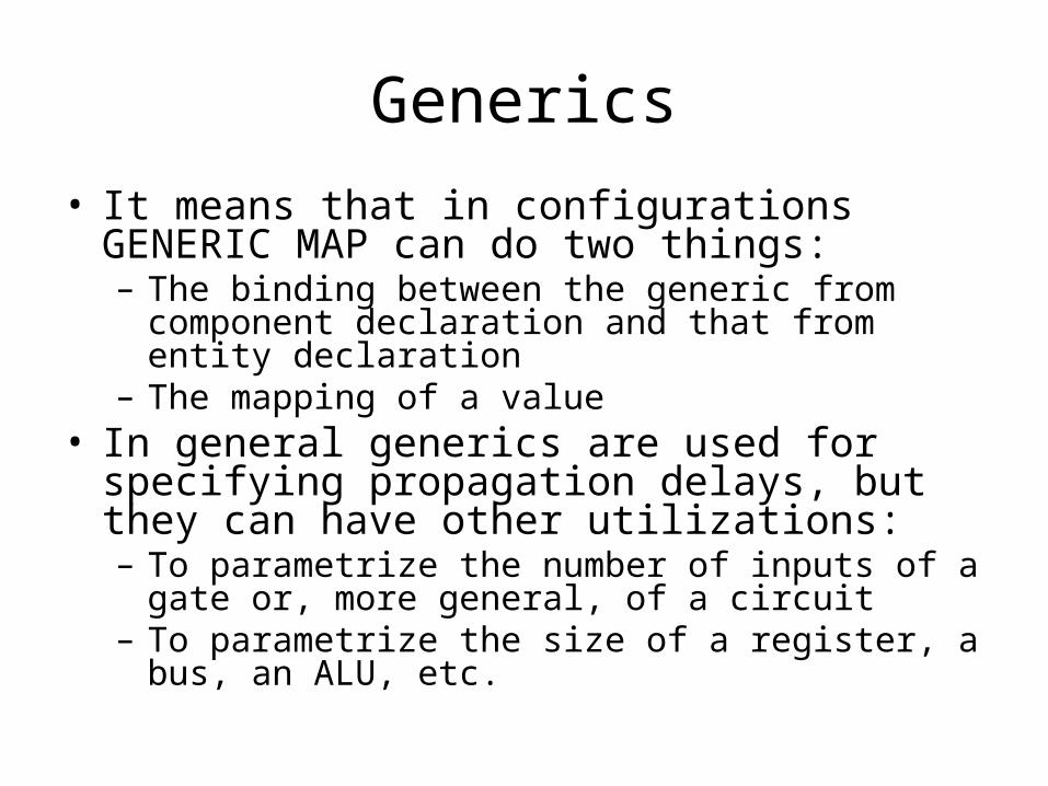
• It means that in configurations GENERIC MAP can do two things:– The binding between the generic from component
declaration and that from entity declaration– The mapping of a value
• In general generics are used for specifying propagation delays, but they can have other utilizations:– To parametrize the number of inputs of a gate or,
more general, of a circuit– To parametrize the size of a register, a bus, an ALU,
etc.

Example: N inputs gateENTITY generic_or_gate IS
GENERIC( del: TIME:=5ns; n: INTEGER:=2);PORT(x: IN BIT_VECTOR(n-1 DOWNTO 0); y : OUT BIT);
END generic_or_gate;ARCHITECTURE behave OF generic_or_gate ISBEGIN PROCESS(x)
VARIABLE: temp: BIT:=‘0’; BEGIN
temp:=‘0’;FOR i IN n-1 DOWNTO 0 LOOP
temp:=temp OR x(i);EXIT WHEN temp=‘1’;
END LOOP;y<= temp AFTER del;
END PROCESS;END ARCHITECTURE;

Register example
ENTITY gen_register IS
GENERIC(n: NATURAL:=8);
PORT( parallel_in: IN BIT_VECTOR(n-1 DOWNTO 0);
parallel_out: OUT BIT_VECTOR(n-1 DOWNTO 0);
reset, clock, command1, command2: IN BIT;
serial_in: IN BIT);
END gen_register;

5.3. Configurations
• Have two utilizations:– The binding between an entity and one of its
architectures (the example with the parity generator)
– The binding between a component and the corresponding entity-architecture pair• In structural descriptions• It is the typical utilization
• There exists:1. Configuration specification2. Configuration declaration

Configurations
• Configuration specification– The binding is done in the architecture body– Used for small projects (the architecture must be
recompiled if there are changes)• Configuration declaration
– It is a separate design unit– Advantage: does not need the recompilation of the
architecture if we make changes• A component instantiation may not be bound
in both configuration specification and configuration declaration, but only in one of them.

Configurations
• There are two styles of configurations:1. With entity-architecture pairs
– It is used USE ENTITY WORK.entity(architecture);
2. The lower level configuration:– Configurations are used in order to bind components to
entities pt a lega componente de entitati;– In the form: USE CONFIGURATION
WORK.configuration_name;
– The difference between the two styles appears if the architecture of the entity associated to the component is modelled structurally

Configurations: examples
inv
a b
Suppose that we have an inverter gate named inv, with one input a and one output b, like in next figure:
Suppose that we have an entity test, without ports, that contains a component named neg, which will be bond to the entity inv, and two internal signals, s1 and s2, connected like in next figure:
et
s1 s2
test
Fig 6. Inveter
Fig 7. Entity test that contains the inverter
Configurations: examples
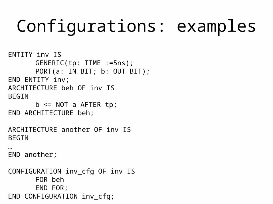
ENTITY inv ISGENERIC(tp: TIME :=5ns);PORT(a: IN BIT; b: OUT BIT);
END ENTITY inv;ARCHITECTURE beh OF inv ISBEGIN
b <= NOT a AFTER tp;END ARCHITECTURE beh;
ARCHITECTURE another OF inv ISBEGIN…END another;
CONFIGURATION inv_cfg OF inv ISFOR behEND FOR;
END CONFIGURATION inv_cfg;

Configuration specification: exampleENTITY test IS
END test;
ARCHITECTURE netlist_config_spec OF test IS
COMPONENT neg IS
GENERIC (tp: TIME :=3ns);
--GENERIC(tp1: TIME :=3ns);
PORT(x: IN BIT; y : OUT BIT);
END COMPONENT;
SIGNAL s1, s2: BIT;
FOR et:neg -- FOR ALL:neg -- FOR OTHERS:neg
USE ENTITY WORK.inv(beh)
--USE CONFIGURATION WORK.inv_cfg
GENERIC MAP(tp =>7ns)-- GENERIC MAP(tp => tp1)
PORT MAP(a=>x, b=>y);
BEGIN
et: neg GENERIC MAP(10ns) PORT MAP(s1,s2);
END ARCHITECTURE;
Configuration specificationSynthax:
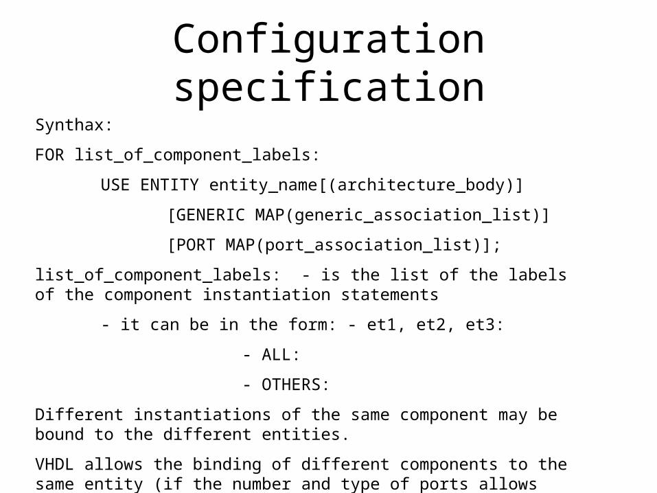
FOR list_of_component_labels:
USE ENTITY entity_name[(architecture_body)]
[GENERIC MAP(generic_association_list)]
[PORT MAP(port_association_list)];
list_of_component_labels: - is the list of the labels of the component instantiation statements
- it can be in the form: - et1, et2, et3:
- ALL:
- OTHERS:
Different instantiations of the same component may be bound to the different entities.
VHDL allows the binding of different components to the same entity (if the number and type of ports allows that) – for debugging, but it is confuzing !
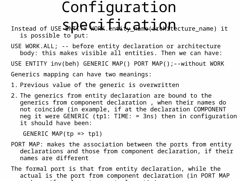
Configuration specificationInstead of USE ENTITY WORK.entity_name(architecture_name) it is possible to put:
USE WORK.ALL; -- before entity declaration or architecture body: this makes visible all entities. Then we can have:
USE ENTITY inv(beh) GENERIC MAP() PORT MAP();--without WORK
Generics mapping can have two meanings:
1. Previous value of the generic is overwritten
2. The generics from entity declaration are bound to the generics from component declaration , when their names do not coincide (in example, if at the declaration COMPONENT neg it were GENERIC (tp1: TIME: = 3ns) then in configuration it should have been:
GENERIC MAP(tp => tp1)
PORT MAP: makes the association between the ports from entity declarations and those from component declaration, if their names are different
The formal port is that from entity declaration, while the actual is the port from component declaration (in PORT MAP we have (formal_port => actual_port) )
The drawback of configuration specification is that when there are changes (a component is associated to another entity or architecture), the entire architecture should be recompiled. This drawback is removed by configuration declaration.
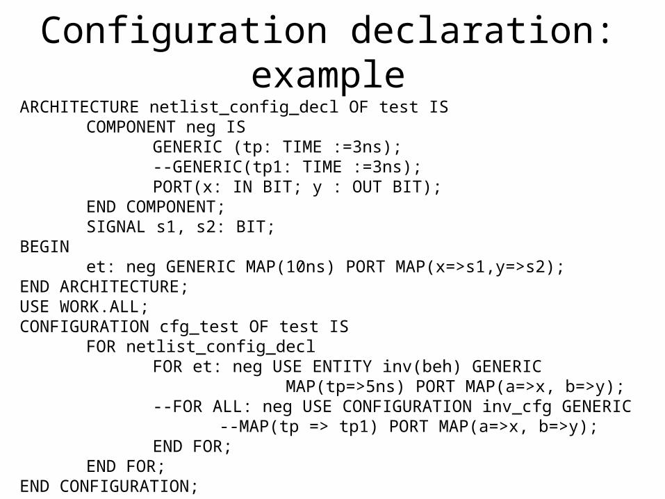
Configuration declaration: exampleARCHITECTURE netlist_config_decl OF test IS
COMPONENT neg ISGENERIC (tp: TIME :=3ns);--GENERIC(tp1: TIME :=3ns);PORT(x: IN BIT; y : OUT BIT);
END COMPONENT;SIGNAL s1, s2: BIT;
BEGINet: neg GENERIC MAP(10ns) PORT MAP(x=>s1,y=>s2);
END ARCHITECTURE;USE WORK.ALL;CONFIGURATION cfg_test OF test IS
FOR netlist_config_declFOR et: neg USE ENTITY inv(beh) GENERIC
MAP(tp=>5ns) PORT MAP(a=>x, b=>y);--FOR ALL: neg USE CONFIGURATION inv_cfg GENERIC
--MAP(tp => tp1) PORT MAP(a=>x, b=>y);END FOR;
END FOR;END CONFIGURATION;
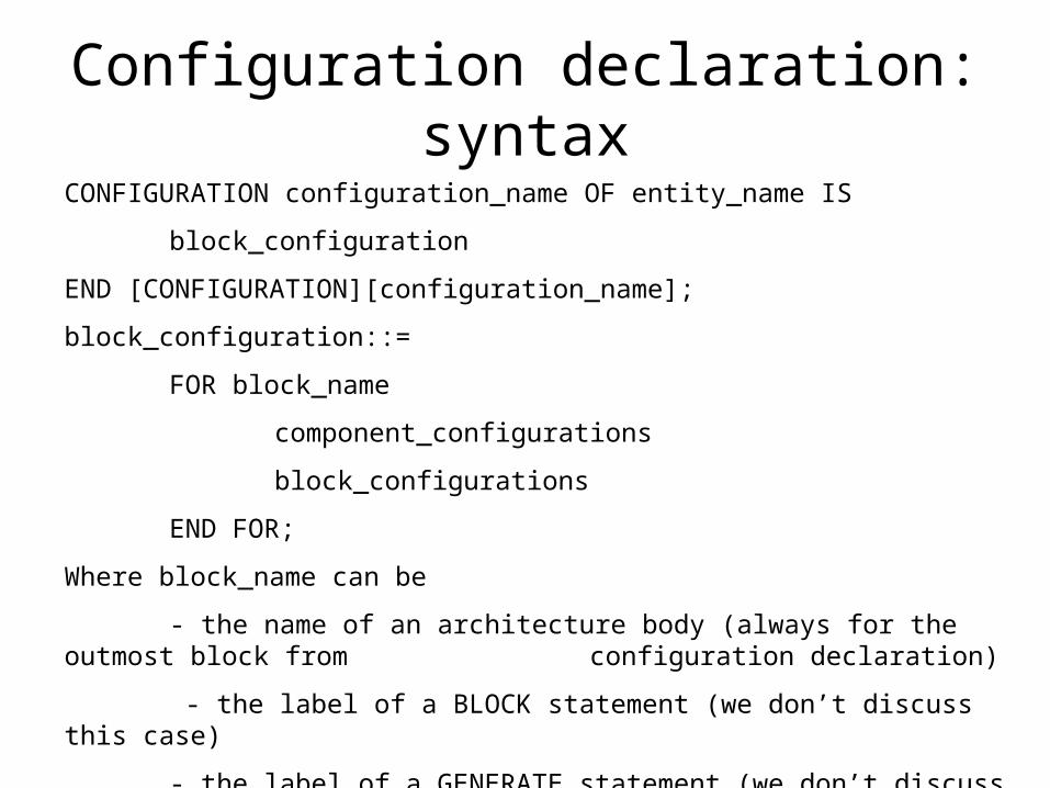
Configuration declaration: syntax
CONFIGURATION configuration_name OF entity_name IS
block_configuration
END [CONFIGURATION][configuration_name];
block_configuration::=
FOR block_name
component_configurations
block_configurations
END FOR;
Where block_name can be
- the name of an architecture body (always for the outmost block from configuration declaration)
- the label of a BLOCK statement (we don’t discuss this case)
- the label of a GENERATE statement (we don’t discuss this case)
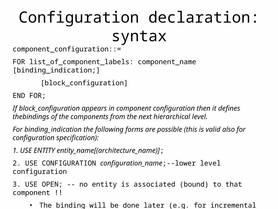
Configuration declaration: syntaxcomponent_configuration::=
FOR list_of_component_labels: component_name [binding_indication;]
[block_configuration]
END FOR;
If block_configuration appears in component configuration then it defines thebindings of the components from the next hierarchical level.
For binding_indication the following forms are possible (this is valid also for configuration specification):
1. USE ENTITY entity_name[(architecture_name)];
2. USE CONFIGURATION configuration_name;--lower level configuration
3. USE OPEN; -- no entity is associated (bound) to that component !!
• The binding will be done later (e.g. for incremental configurations)

Lower level configurationNext example shows the difference between lower level configuration and entity – architecture pairs configurations, in a structural model that contains several hierarchic levels.
Entity test from previous examples is now a component of another entity, named big_test, that has no ports, like in the next figure:
et
a b
et1
test
big_test
We present one example of lower level configuration, and one example of entity-architecture style configuration, for the configuration of the entity big_test.
Fig 8. Entity big_test, which contains the entity test from fig 7.

Entity big_test with its architecture and a lower level style configuration:
ENTITY big_test ISEND big_test;ARCHITECTURE netlist OF big_test IS
COMPONENT test ISEND COMPONENT;
BEGINet1: testEND ARHITECTURE netlist;CONFIGURATION cfg_big_test OF big_test IS
FOR netlistFOR ALL: test USE CONFIGURATION WORK.cfg_test;END FOR;
END FOR;END CONFIGURATION;
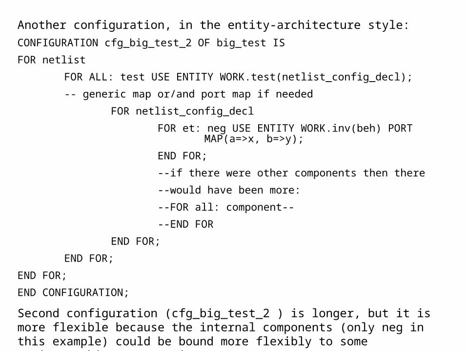
Another configuration, in the entity-architecture style:
CONFIGURATION cfg_big_test_2 OF big_test IS
FOR netlist
FOR ALL: test USE ENTITY WORK.test(netlist_config_decl);
-- generic map or/and port map if needed
FOR netlist_config_decl
FOR et: neg USE ENTITY WORK.inv(beh) PORT MAP(a=>x, b=>y);
END FOR;
--if there were other components then there
--would have been more:
--FOR all: component--
--END FOR
END FOR;
END FOR;
END FOR;
END CONFIGURATION;
Second configuration (cfg_big_test_2 ) is longer, but it is more flexible because the internal components (only neg in this example) could be bound more flexibly to some entity(architecture) pairs.
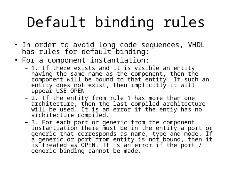
Default binding rules
• In order to avoid long code sequences, VHDL has rules for default binding:
• For a component instantiation:– 1. If there exists and it is visible an entity having the same name
as the component, then the component will be bound to that entity. If such an entity does not exist, then implicitly it will appear USE OPEN
– 2. If the entity from rule 1 has more than one architecture, then the last compiled architecture will be used. It is an error if the entiy has no architecture compiled.
– 3. For each port or generic from the component instantiation there must be in the entity a port or generic that corresponds as name, type and mode. If a generic or port from entity is not bound, then it is treated as OPEN. It is an error if the port / generic binding cannot be made.
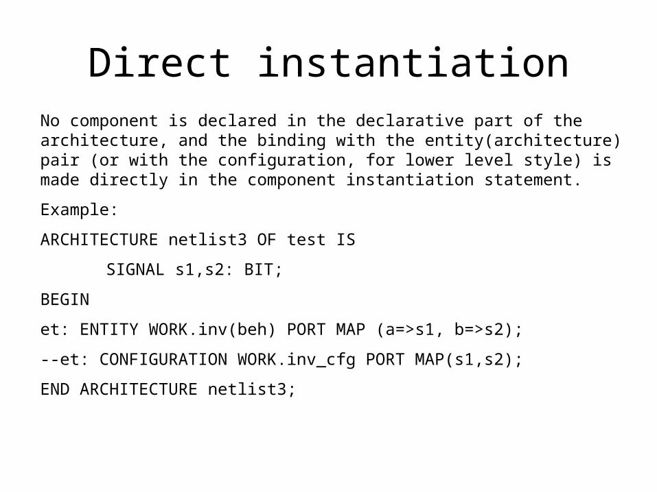
Direct instantiationNo component is declared in the declarative part of the architecture, and the binding with the entity(architecture) pair (or with the configuration, for lower level style) is made directly in the component instantiation statement.
Example:
ARCHITECTURE netlist3 OF test IS
SIGNAL s1,s2: BIT;
BEGIN
et: ENTITY WORK.inv(beh) PORT MAP (a=>s1, b=>s2);
--et: CONFIGURATION WORK.inv_cfg PORT MAP(s1,s2);
END ARCHITECTURE netlist3;

Direct instantiation: syntax
The syntax for direct instantiation statement is:
component_label: ENTITY entity_name[(architecture_name)]
[GENERIC MAP (generic_association_list)]
[PORT MAP (port_association_list)];
Or:component_label: CONFIGURATION configuration_name
[GENERIC MAP (generic_association_list)][PORT MAP (port_association_list)];
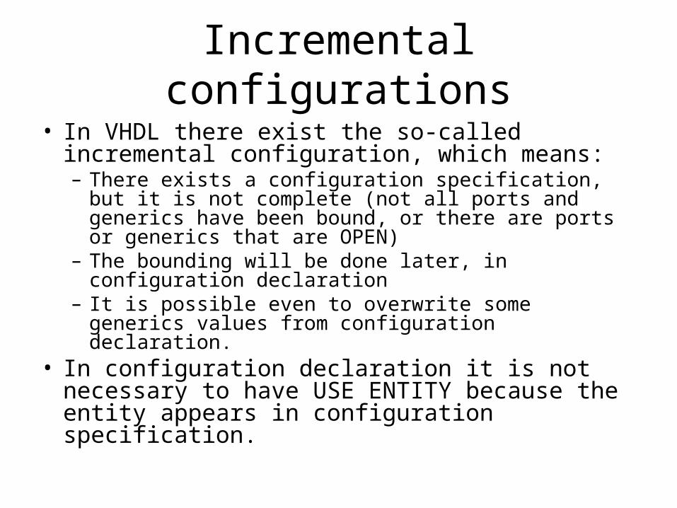
Incremental configurations
• In VHDL there exist the so-called incremental configuration, which means:– There exists a configuration specification, but it is not
complete (not all ports and generics have been bound, or there are ports or generics that are OPEN)
– The bounding will be done later, in configuration declaration
– It is possible even to overwrite some generics values from configuration declaration.
• In configuration declaration it is not necessary to have USE ENTITY because the entity appears in configuration specification.

The board-socket-chip analogy • Proposed by Alec Stanculescu• An entity which is modelled structurally can be
compared to a board on which the circuit is implemented
• The architecture of the entity corresponds to the stage when sockets are connected on the board through conductive traces:– component instantiations = sockets– PORT MAP = traces
• In this moment the board is not functional yet, because no circuits have been put in the sockets– This stage corresponds to VHDL configuration -> the
board will be functional (in VHDL we bind components to entities).
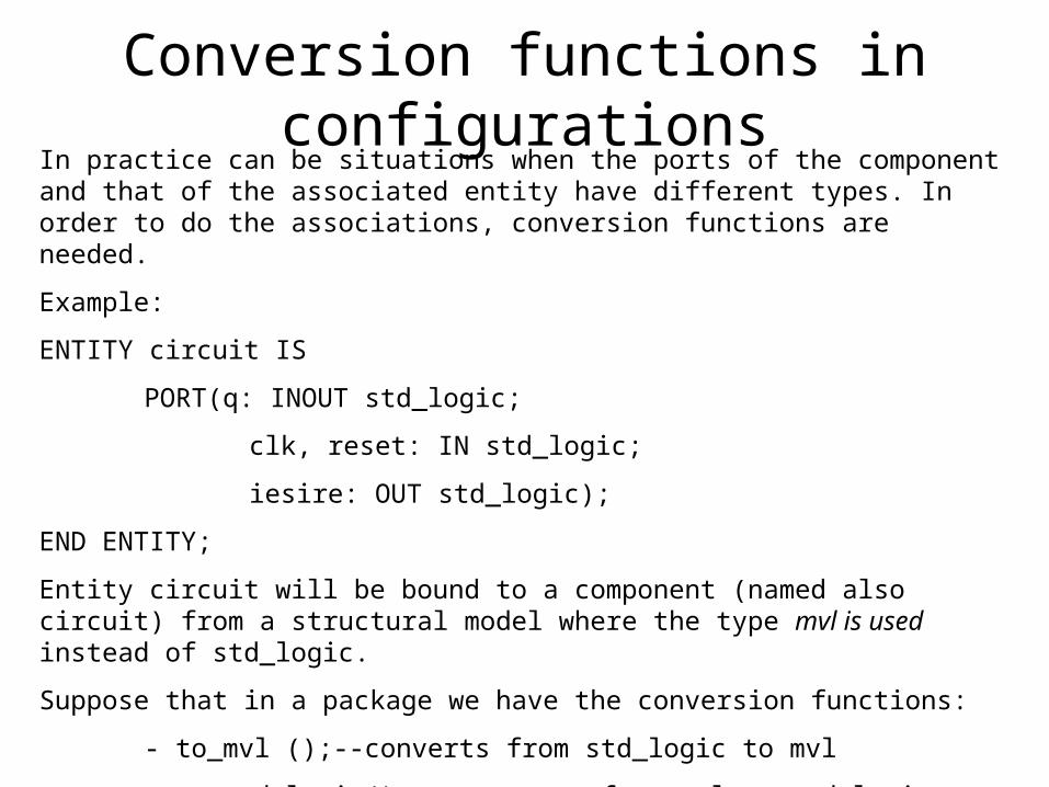
Conversion functions in configurationsIn practice can be situations when the ports of the component and that of the associated entity have different types. In order to do the associations, conversion functions are needed.
Example:
ENTITY circuit IS
PORT(q: INOUT std_logic;
clk, reset: IN std_logic;
iesire: OUT std_logic);
END ENTITY;
Entity circuit will be bound to a component (named also circuit) from a structural model where the type mvl is used instead of std_logic.
Suppose that in a package we have the conversion functions:
- to_mvl ();--converts from std_logic to mvl
- to_std_logic();-- converts from mvl to std_logic

Conversion functions in configurationsPACKAGE conversions IS
FUNCTION to_mvl(x: IN std_logic) RETURN mvl;
FUNCTION to_std_logic(x: IN mvl) RETURN std_logic;
END PACKAGE;
PACKAGE BODY conversions IS
….
END PACKAGE BODY;
USE WORK.conversions.ALL;.—for making visible the types std_logic and mvl
ENTITY x IS
END;
ARCHITECTURE y OF x ISCOMPONENT circuit IS
PORT(ctr: INOUT mvl;clk, res: IN mvl;ies: OUT mvl);
END COMPONENT;
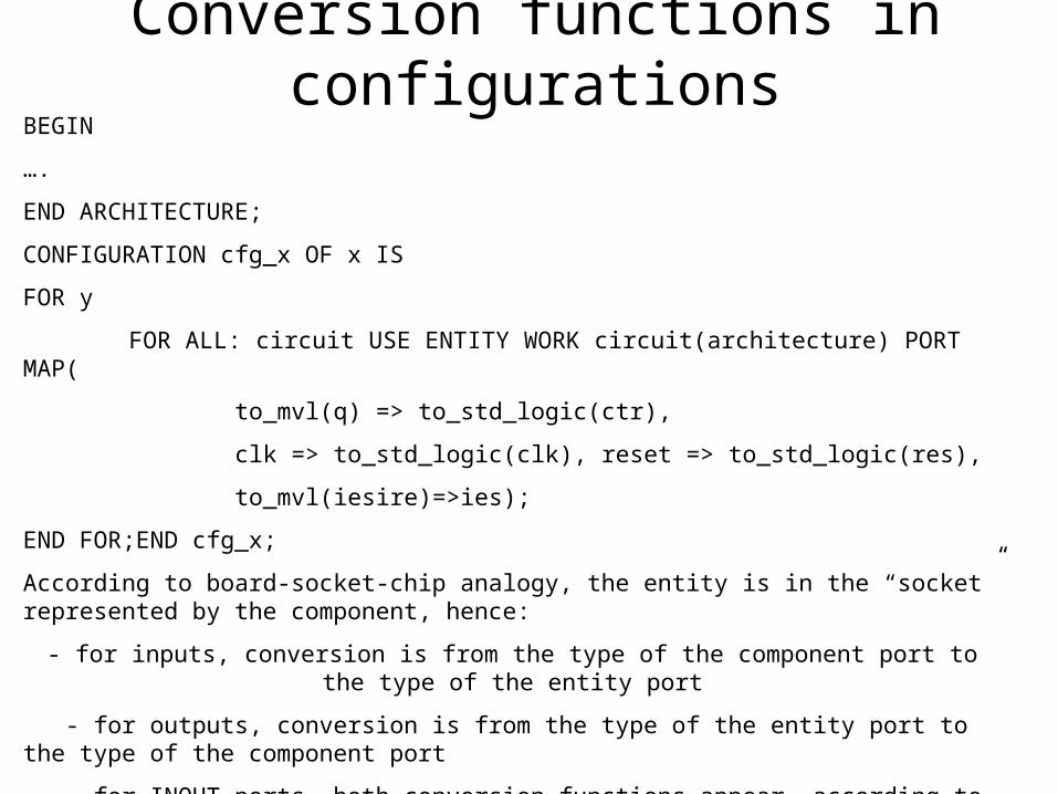
Conversion functions in configurationsBEGIN
….
END ARCHITECTURE;
CONFIGURATION cfg_x OF x IS
FOR y
FOR ALL: circuit USE ENTITY WORK circuit(architecture) PORT MAP(
to_mvl(q) => to_std_logic(ctr),
clk => to_std_logic(clk), reset => to_std_logic(res),
to_mvl(iesire)=>ies);
END FOR;END cfg_x;
According to board-socket-chip analogy, the entity is in the “socket” represented by the component, hence:
- for inputs, conversion is from the type of the component port to the type of the entity port
- for outputs, conversion is from the type of the entity port to the type of the component port
- for INOUT ports, both conversion functions appear, according to the direction of the flow of information.

COMPONENT circuit
ENTITY circuitclk
res
clk
reset
q
ctr
iesire ies
Fig 9. Conversion functions in configurations.
Conversion functions
• Are can be used whenever there is a binding beteeen generics, ports or parameters in:– Function calls– Procedure calls– Port map – Generic map
Top Related