


Languages
Pages
Legal

ST.JOSEPH COLLEGE OF ENGINEERING
DEPARTMENT OF ECE
SUBJECT: EC 6651- COMMUNICATION ENGINEERING STAFF : MARGARET.T
UNIT I
ANALOG COMMUNICATION
1. What is the need for modulation? (April-May 09 & 11)
Base band transmission has many limitations which can be overcome by using modulation, since
modulation shifts low frequency to high and reduce the size of the antenna, avoid mixing of
signals, increase the range and quality of communication.
2. What is super heterodyne receiver? (April-May 09 & 11) Heterodyne means to mix two frequencies together in a nonlinear device or to translate one
frequency to another using nonlinear mixing.
There are five sections to a super heterodyne receiver: that are RF section, Mixer/converter
section, IF section, Audio detector section, and Amplifier section.
3. State the advantages of FM over AM. (Nov-Dec 09) Frequency modulation is one type of angle modulation this has the advantages over
amplitude modulation such as Noise reduction, improved system fidelity and more efficient use of
power.
4. What are the advantages of the super heterodyne receiver? (April-May09) Advantages in SH Receiver over TRF receivers are Improved the selectivity in terms of
adjacent channels, more uniform selectivity over frequency range, improved in receiver stability,
higher gain per stage and uniform bandwidth.
5. State the advantages of FM over AM. (Nov-Dec 09) Frequency modulation is one type of angle modulation this has the advantages over
amplitude modulation such as Noise reduction, improved system fidelity and more efficient use of
power.
6. Define standing wave ratio. (Nov-Dec 09)
Standing wave the is ratio between the reflected wave and normal wave components
voltage/current at any point is known as SWR, the plot of resultant voltage or current along the line
length is termed as standing waves.
7. A carrier signal with power of 40Watts is amplitude modulated by a sinusoidal signal.
Find the power of the modulated signal if the modulation index is 0.7.
Solution: ( Nov-Dec 09)
Carrier power Pc= 40 Watts and m=0.7
Modulated power is P Total =Pc(1+(m)2/2) =
49.8Watts
ST.JOSEPH COLLEGE OF ENGINEERING
DEPARTMENT OF ECE
SUBJECT: EC 6651- COMMUNICATION ENGINEERING STAFF : MARGARET.T
8. Define Low level Modulation.
In low level modulation, modulation takes place prior to the output element of the final stage
of the transmitter. For low level AM class A amplifier is used.
9. Define High level Modulation.
In high level modulators, the modulation takes place in the final element of the final stage
where the carrier signal is at its maximum amplitude. For high level modulator class C amplifier
is used.
10. What is the advantage of low level modulation?
An advantage of low level modulation is that less modulating signal power is required to
achieve a high percentage of modulation.
11. Define Modulation and Amplitude Modulation.
Modulation is the process of varying one or more properties of a periodic waveform, called
the carrier signal, with a modulating signal which typically contains information to be
transmitted.
Amplitude Modulation is the process of changing the amplitude of a relatively high frequency
carrier signal in proportion with the instantaneous value of the modulating signal.
12. Define Modulation index.
Modulation index is a term used to describe the amount of amplitude change present in an
AM waveform .It is also called as coefficient of modulation. Mathematically modulation index is
m = Em / Ec
Where m = Modulation coefficient
Em = Peak change in the amplitude of the output waveform voltage. Ec
= Peak amplitude of the unmodulated carrier voltage.
13. Define Percentage modulation for an AM wave.
Percent modulation gives the percentage change in the amplitude of the output wave when
the carrier is acted on by a modulating signal.
14. Distinguish between low level and high level modulation.
S.No Low level modulation High level modulation
1 Modulation takes place in prior to the output ent of the final stage of the Transmitter
Modulation takes place in the t of the final stage where carrier signal is at
aximum amplitude.
2 It requires less power to achieve a high entage of modulation.
It requires much higher amplitude of modulating signal to achieve a reasonable
percent modulation
15. Define Local Oscillator tracking.
Tracking is the ability of the local oscillator in a receiver to oscillate either above or below
the selected radio frequency carrier by an amount equal to the intermediate frequency throughout
the entire radio frequency band
ST.JOSEPH COLLEGE OF ENGINEERING
DEPARTMENT OF ECE
SUBJECT: EC 6651- COMMUNICATION ENGINEERING STAFF : MARGARET.T
16. Define High side injection tracking.
In high side injection tracking, the local oscillator should track above the incoming RF carrier
by a fixed frequency equal to fRF +fIF.
17. Define Low side injection tracking.
In low side injection tracking, the local oscillator should track below the RF carrier by a fixed
frequency equal to fRF -fIF.
18. Define tracking error. How it is reduced.
The difference between the actual local oscillator frequency and the desired frequency is
called tracking error. It is reduced by a technique called three point tracking.
19. Define Heterodyning.
Heterodyne means to mix two frequencies together in a nonlinear device or to translate one
frequency to another using nonlinear mixing.
20. Explain the disadvantages of conventional/double side band full carrier system.
In conventional AM, carrier power constitutes two thirds or more of the total transmitted
power. This is a major drawback because the carrier contains no information; the sidebands contain
the information.
Second, conventional AM systems utilize twice as much bandwidth as needed with single
sideband systems.
16 MARK QUESTIONS
1. Explain the operation of Super heterodyne receiver and compare its performance
with Tunal Radio frequency receiver.
2. Explain the principle of AM, modulation index, sidebands and power considerations.
3. Explain the detection of AM signal using envelope detector and draw the block
diagram of FM receiver.
4. Explain different types of modulation systems.
5. Derive time and frequency domain representation of single frequency AM wave.
6. Explain the generation of AM in low and high level modulation.
7. Explain two types of AM detector with advantages, disadvantages and applications.
8. Explain brief about Armstrong method and Reactance modulations.
ST.JOSEPH COLLEGE OF ENGINEERING
DEPARTMENT OF ECE
SUBJECT: EC 6651- COMMUNICATION ENGINEERING STAFF : MARGARET.T
UNIT II
DIGITAL COMMUNICATION
1. State Shannon’s fundamental theorem of information capacity.
The information capacity of a communication system represents the number
of independent symbols that can be carried through that system in a given unit of
time.
It is expressed in bits per sec
The information capacity of Gaussian channel is given
by I=B log2 (1+S/N) bps
power
the channel.
2. Define bit rate and baud rate.
Bit rate refers to the rate of change of a digital information signal which is usually
binary. Unit is bpsBaud rate is also a rate of change, it refers to the rate of change of a signal
on the transmission medium after encoding and modulation. Unit is baud
3. Write the advantages of BPSK.
i) BPSK has a Bandwidth which is lower than that of a BFSK signal.
ii) BPSK has the best performance of all the systems in presence of noise.
iii) It gives the minimum possibility of error.
iv) BPSK has very good noise immunity.
4. Compare Bandwidth efficiency of BPSK and QPSK modulated signals.
Bandwidth of BPSK =fb
Bandwidth of QPSK = fb/2
Where fb is the input data rate
5. What is digital transmission?
Transmission of digital signals between two or more points in a communication
system. The original information can be of analog or digital. If it is analog then it is
converted to digital.
6. List the effects of ‘M’ in M-ary digital modulation technique.
M-ary encoding system able to transmit information at a rate that is log 2M faster than
the binary PAM system for a fixed channel bandwidth. M-ary system requires more
transmitted power.
7. What is meant by non-coherent digital modulation technique?
Non-coherent digital modulation technique is the system in which a synchronous carrier
is not used
ST.JOSEPH COLLEGE OF ENGINEERING
DEPARTMENT OF ECE
SUBJECT: EC 6651- COMMUNICATION ENGINEERING STAFF : MARGARET.T
8. What is meant by carrier recovery?
Carrier is the process of extracting a phase coherent reference carrier from a received
signal.
It is also called as phase referencing.
9. What are the types of carrier recovery?
Two types of carrier recovery circuits are
i) Squaring loop
ii) Costas loop
10. What is meant by offset QPSK?
Offset QPSK is the modified form of QPSK, where the bit waveforms on the I
channel and Q channels are shifted in phase from each other by one-half of a bit time.
11. Calculate the capacity of a standard 4 KHz telephone channel with a 30 dBsignal
to noise ratio?
Given:
B =4 KHz
S/N =30dB
Soln: I=3.32B log10 (1+S/N)
3 =3.32(4x10 ) log10
3
(1+1000) =39.84x10
=39.84Kbps
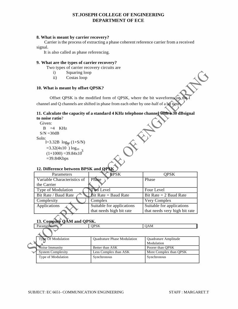
12. Difference between BPSK and QPSK
Parameters BPSK QPSK
Variable Characteristics of
the Carrier
Phase Phase
Type of Modulation Two Level Four Level
Bit Rate / Baud Rate Bit Rate = Baud Rate Bit Rate = 2 Baud Rate
Complexity Complex Very Complex
Applications Suitable for applications
that needs high bit rate
Suitable for applications
that needs very high bit rate
13. Compare QAM and QPSK. Parameter QPSK QAM
Type Of Modulation Quadrature Phase Modulation Quadrature Amplitude
Modulation
Noise Immunity Better than ASK Poorer than QPSK
System Complexity Less Complex than ASK More Complex than QPSK
Type of Modulation Synchronous Synchronous
ST.JOSEPH COLLEGE OF ENGINEERING
DEPARTMENT OF ECE
SUBJECT: EC 6651- COMMUNICATION ENGINEERING STAFF : MARGARET.T
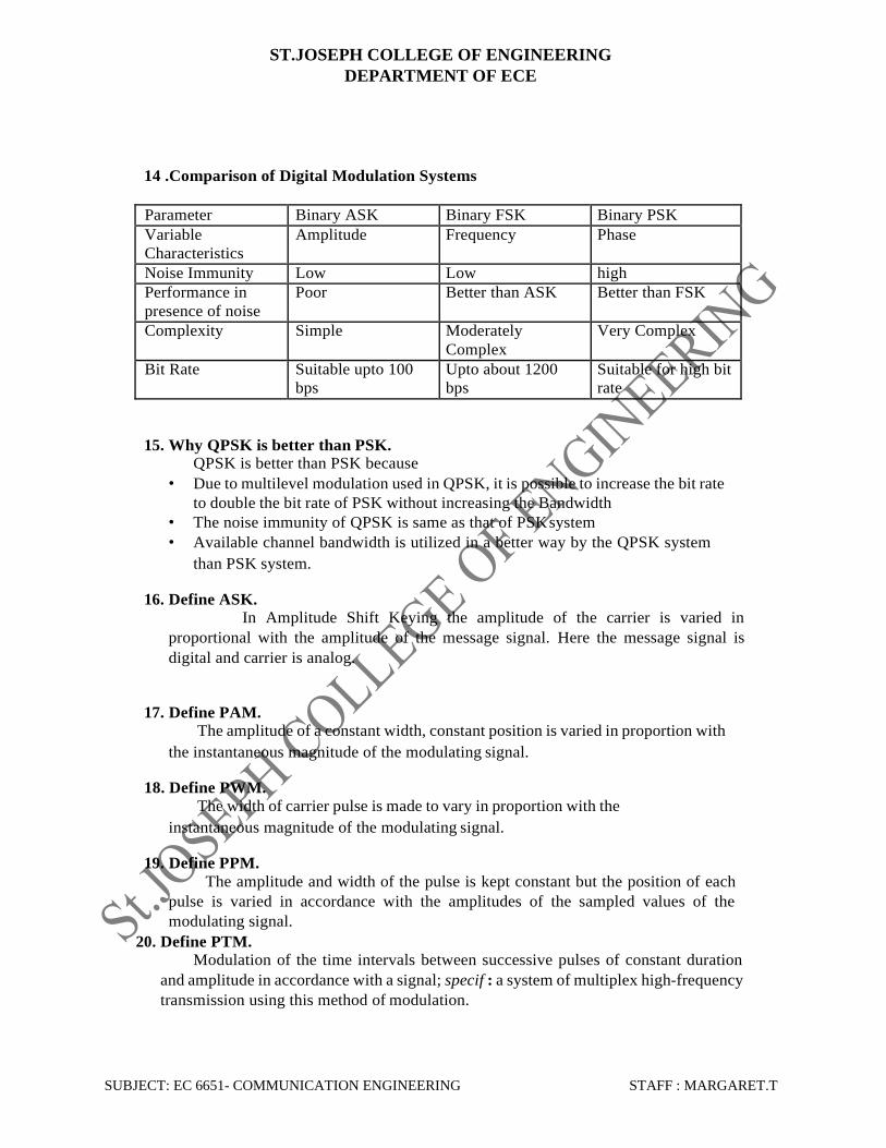
14 .Comparison of Digital Modulation Systems
Parameter Binary ASK Binary FSK Binary PSK
Variable
Characteristics
Amplitude Frequency Phase
Noise Immunity Low Low high
Performance in
presence of noise
Poor Better than ASK Better than FSK
Complexity Simple Moderately
Complex
Very Complex
Bit Rate Suitable upto 100
bps
Upto about 1200
bps
Suitable for high bit
rate
15. Why QPSK is better than PSK.
QPSK is better than PSK because
• Due to multilevel modulation used in QPSK, it is possible to increase the bit rate
to double the bit rate of PSK without increasing the Bandwidth
• The noise immunity of QPSK is same as that of PSK system
• Available channel bandwidth is utilized in a better way by the QPSK system
than PSK system.
16. Define ASK.
In Amplitude Shift Keying the amplitude of the carrier is varied in
proportional with the amplitude of the message signal. Here the message signal is
digital and carrier is analog.
17. Define PAM.
The amplitude of a constant width, constant position is varied in proportion with
the instantaneous magnitude of the modulating signal.
18. Define PWM.
The width of carrier pulse is made to vary in proportion with the
instantaneous magnitude of the modulating signal.
19. Define PPM.
The amplitude and width of the pulse is kept constant but the position of each
pulse is varied in accordance with the amplitudes of the sampled values of the
modulating signal.
20. Define PTM.
Modulation of the time intervals between successive pulses of constant duration
and amplitude in accordance with a signal; specif : a system of multiplex high-frequency
transmission using this method of modulation.
ST.JOSEPH COLLEGE OF ENGINEERING
DEPARTMENT OF ECE
SUBJECT: EC 6651- COMMUNICATION ENGINEERING STAFF : MARGARET.T
16 MARKS QUESTIONS
1. Explain the transmitter and receiver block diagram of PCM.
2. Explain the Quantization noise in PCM system. How can it be reduced?
3. Explain the functioning of a FSK digital transmitter cum receiver operation
in detail with the relevant diagrams.
4. Explain in detail about the Binary phase shift keying and its Bandwidth
considerations.
5. Explain the functioning of a ASK and PSK digital transmitter cum receiver
operation.
6. Explain in detail about the QAM and MSK and its waveform.
7. Explain the necessity of using the digital modulation and Compare
various digital modulation methods.
8. Explain in detail about the PAM and PWM and its waveform.
UNIT III
SOURCE CODES, LINE CODES AND ERROR CONTROL
1. Define Shannon Entropy.
Shannon entropy, which quantifies the expected value of the information
contained in a message. Entropy is typically measured in bits, nats, or bans. Shannon
entropy is the average unpredictability in a random variable, which is equivalent to its
information content.
2. Define Shannon source coding theorem.
Shannon's source coding theorem (or noiseless coding theorem) establishes
the limits to possible data compression, and the operational meaning of the Shannon entropy.
3. Define Shannon limit.
The Shannon limit or Shannon capacity of a communications channel is the
theoretical maximum information transfer rate of the channel, for a particular noise level.
4. Define Huffman coding.
Huffman coding is an entropy encoding algorithm used for lossless data
compression. The term refers to the use of a variable-length code table for encoding a source
symbol (such as a character in a file) where the variable-length code table has been derived in
a particular way based on the estimated probability of occurrence for each possible value of
the source symbol.
5. What are the uses of Modified Huffman coding.
ST.JOSEPH COLLEGE OF ENGINEERING
DEPARTMENT OF ECE
SUBJECT: EC 6651- COMMUNICATION ENGINEERING STAFF : MARGARET.T
Modified Huffman coding is used in fax machines to encode black on
white images (bitmaps). It combines the variable length codes of Huffman coding with
the coding of repetitive data in run-length encoding.
6. Define SNR.
Ratio of signal power to the noise power, often expressed in decibels. A
ratio higher than 1:1 (greater than 0 dB) indicates more signal than noise.
7. Define NRZ.
Non-return-to-zero (NRZ) line code is a binary code in which 1s are
represented by one significant condition (usually a positive voltage) and 0s are represented by
some other significant condition (usually a negative voltage), with no other neutral or rest
condition.
8. Define RZ.
Return-to-zero (RZ) describes a line code used in telecommunication signals in
which the signal drops (returns) to zero between each pulse. This takes place even if a
number of consecutive 0's or 1's occur in the signal. The signal is self-clocking.
9. Define Error control coding.
Error control coding aims at developing methods for coding to
check the correctness of the bit stream transmitted. The bit stream representation of a
symbol is called the codeword of that symbol.
10. Mention the types of error
Linear Block Codes Repetition
Codes
Convolution Codes
11. Define linear block codes.
A code is linear if two codes are added using modulo-2 arithmetic produces a third
codeword in the code. Consider a (n, k) linear block code. Here,
1. n represents the codeword length
2. k is the number of message bit
3. n − k bits are error control bits or parity check bits
generated from message using an appropriate rule.
12. Define Repetition Codes. This is the simplest of linear block codes. Here, a single message bit is encoded into a
block of n identical bits, producing an (n, 1) block code. This code allows variable amount
of redundancy. It has only two codewords - all-zero codeword and all-one codeword.
13. Define convolution Codes.
A convolution code is a type of error-correcting code in which each m-bit information
symbol (each m-bit string) to be encoded is transformed into an n-bit symbol, where m/n is the
code rate (n ≥ m) and

ST.JOSEPH COLLEGE OF ENGINEERING
DEPARTMENT OF ECE
SUBJECT: EC 6651- COMMUNICATION ENGINEERING STAFF : MARGARET.T
The transformation is a function of the last k information symbols, where k is the
constraint length of the code.
14. Define Block Codes.
Block codes comprise the large and important family of error-correcting codes that
encode data in blocks. Block Codes are conceptually useful because they allow coding
theorists, mathematicians, and computer scientists to study the limitations of all block
codes in a unified way. Such limitations often take the form of bounds that relate different
parameters of the block code to each other, such as its rate and its ability to detect and
correct errors.
15. Define Modified AMI Codes.
Modified AMI codes are Alternate Mark Inversion (AMI) line codes in which
bipolar violations may be deliberately inserted to maintain system synchronization. There are
several types of modified AMI codes, used in various T-carrier and E-carrier systems.
16. Define Shannon–Fano coding. In Shannon–Fano coding, the symbols are arranged in order from most probable to least
probable, and then divided into two sets whose total probabilities are as close as possible to
being equal. All symbols then have the first digits of their codes assigned; symbols in the first
set receive "0" and symbols in the second set receive "1".
17. What are the advantages of single sideband transmission?
The advantages of SSBSC are
1. Power conservation: Normally, with single side band transmission, only one sideband is
transmitted and the carrier is suppressed. So less power is required to produce essentially the
same quality signal.
2. Bandwidth conservation: Single sideband transmission requires half as much bandwidth as
conventional AM double side band transmission.
3. Noise reduction: Because a single side band system utilizes half as much bandwidth as
conventional AM, the thermal noise power is reduced to half that of a double side band
system
18. What are the disadvantages of single side band transmission?
1. Complex receivers: Single side band systems require more complex and expensive receivers
than conventional AM transmission.
2. Tuning Difficulties: Single side band receivers require more complex and precise tuning than
conventional AM receivers.
19. Define pulse code modulation.
In pulse code modulation, analog signal is sampled and converted to fix length, serial binary
number for transmission. The binary number varies according to the amplitude of the analog
signal.
ST.JOSEPH COLLEGE OF ENGINEERING
DEPARTMENT OF ECE
SUBJECT: EC 6651- COMMUNICATION ENGINEERING STAFF : MARGARET.T
20. Define critical frequency. (CAU Nov-Dec 09)
Critical frequency is the maximum frequency that the radio wave can be transmitted vertically
and still some of the frequency will be refracted back to the transmitter.
16 MARKS QUESTIONS
1. Explain briefly about BSE and BEC.
2. Explain briefly about Huffman coding.
3. Explain briefly about Convolution and block codes with neat block with example.
4. Define Entropy. List the properties of entropy.
5. Explain briefly about NRZ and RZ codes with examples.
6. Explain briefly about AMI and HDBP codes with examples.
7. Explain briefly about ABQ and MBNB codes with examples.
Explain transmission efficiency, Error control codes and applications.
UNIT IV
MULTIPLE ACCESS TECHNIQUES
1. Define spread spectrum.
Spread-spectrum techniques are methods by which a signal (e.g. an electrical,
electromagnetic, or acoustic signal) generated with a particular bandwidth is deliberately
spread in the frequency domain, resulting in a signal with a wider bandwidth.
2. Mention the uses of spread spectrum.
Used for a variety of reasons, including the establishment of secure
communications, increasing resistance to natural interference, noise and jamming, to
prevent detection, and to limit power flux density (e.g. in satellite downlinks).
3. Define multiple access.
Multiple access defined as a means of allowing multiple users to simultaneously
share the finite bandwidth with least possible degradation in the performance of the system.
4. Mention the types of multiple access.
1. Frequency Division Multiple Access (FDMA)
2. Time Division Multiple Access (TDMA)
3. Code Division Multiple Access (CDMA)
4. Space Division Multiple Access (SDMA)
5. Define Frequency Division Multiple Access (FDMA).
In FDMA, each user is allocated a unique frequency band or channel. During
ST.JOSEPH COLLEGE OF ENGINEERING
DEPARTMENT OF ECE
SUBJECT: EC 6651- COMMUNICATION ENGINEERING STAFF : MARGARET.T
the period of the call, no other user can share the same frequency band.
6. Define Time Division Multiple Access (TDMA).
TDMA systems divide the channel time into frames. Each frame is further
partitioned into time slots. In each slot only one user is allowed to either transmit or receive.
7. Mention the features of FDMA.
Continuous
transmission Narrow
bandwidth Low ISI
Low overhead
Simple hardware at mobile unit and
BS Use of duplexer
8. Mention the features of TDMA.
Multiple channels per carrier or RF channels.
Burst transmission since channels are used on a timesharing basis. Transmitter can be
turned off during idle periods.
Narrow or wide bandwidth – depends on factors such as modulation scheme, number
of voice channels per carrier channel.
High ISI – Higher transmission symbol rate, hence resulting in high ISI.
Adaptive equalizer required.
9. Define CDMA.
CDMA is also called DSSS (Direct Sequence Spread Spectrum).
In CDMA, the narrowband message signal is multiplied by a very large bandwidth
signal called spreading signal (code) before modulation and transmission over the
air. This is called spreading.
10. Spreading signal consists of
Has Chip period and and hence, chip rate
Spreading signal use a pseudo-noise (PN) sequence (a pseudo-
random sequence)
PN sequence is called a codeword
Each user has its own cordword
Codewords are orthogonal. (low autocorrelation)
Chip rate is oder of magnitude larger than the symbol rate.
11. Mention the advantages of CDMA.
Random access possible
Users can start their transmission at any time
Cell capacity is not concerete fixed like in TDMA or FDMA systems. Has soft
capacity
Higher capacity than TDMA and FDMA
No frequency management
No equalizers needed
No guard time needed
Enables soft handoff .
ST.JOSEPH COLLEGE OF ENGINEERING
DEPARTMENT OF ECE
SUBJECT: EC 6651- COMMUNICATION ENGINEERING STAFF : MARGARET.T
12. Define SDMA.
Space-division multiple access (SDMA) is a channel access method based on
creating parallel spatial pipes next to higher capacity pipes through spatial multiplexing
and/or diversity, by which it is able to offer superior performance in radio multiple access
communication systems.
13. Define modal dispersion.
Modal dispersion or pulse spreading is caused by the difference in the propagation
times of light rays that take different paths down a fiber. Modal dispersion can occur only in
multimode fibers. It can be reduced by using single mode step index fibers and graded index
fibers.
14. What are the advantages of hetero junction LEDs?
The increase in current density generates a more brilliant light spot.
The smaller emitting area makes it easier to couple its emitted light into fiber.
The small effective area has a smaller capacitance, which allows the planar hetero
junction LED to be used at higher speeds
15. What are the disadvantages of injection laser diode?
□ILDs are typically on the order of 10 times more expensive than LEDs
□Because ILDs operate at higher powers, they typically have a much shorter life time than LEDs.
□ILDs are more temperature dependent than LEDs.
16. Define instantaneous frequency deviation.
The instantaneous frequency deviation is the instantaneous change in the frequency of the carrier and
is defined as the first derivative of the instantaneous phase deviation.
17.Define frequency deviation.
Frequency deviation is the change in frequency that occurs in the carrier when it is acted on by a
modulating signal frequency. Frequency deviation is typically given as a peak frequency shift in Hertz
(∆f).The peak to peak frequency deviation (2∆f) is sometimes called carrier swing. The peak
frequency deviation is simply the product of the deviation sensitivity and the peak modulating signal
voltage and is expressed mathematically as ∆f=K1 x Vm Hz.
18. Define pulse code modulation.
In pulse code modulation, analog signal is sampled and converted to fix length, serial binary number for
transmission. The binary number varies according to the amplitude of the analog signal
19. Define direct frequency modulation.
In direct frequency modulation, frequency of a constant amplitude carrier signal is directly proportional
to the amplitude of the modulating signal at a rate equal to the frequency of the modulating signal.
ST.JOSEPH COLLEGE OF ENGINEERING
DEPARTMENT OF ECE
SUBJECT: EC 6651- COMMUNICATION ENGINEERING STAFF : MARGARET.T
20. Define critical frequency. (CAU Nov-Dec 09)
Critical frequency is the maximum frequency that the radio wave can be transmitted vertically and still
some of the frequency will be refracted back to the transmitter.
16 MARKS QUESTIONS
1. Explain different types of multiple access techniques.
2. Draw and explain the block diagram of transmitter and receiver of FDMA.
3. Draw and explain the block diagram of transmitter and receiver of TDMA.
4. Draw and explain the block diagram of transmitter and receiver of CDMA.
5. Draw and explain the block diagram of transmitter and receiver of SDMA.
6. Explain the applications of MA in wire and wireless medium.
UNIT V
SATELLITE, OPTICAL FIBER – POWERLINE, SCADA
1. Define protrude orbit. (April-May 09)
If the satellite is orbiting in the same direction as earth’s rotation and at an angular
velocity greater than that of earth, the orbit is called a prograde (or) posigrade orbit.
2. Define retrograde orbit? (April-May 09)
If the satellite is orbiting in the opposite direction as the earth’s rotation or in the same
direction with an angular velocity less than that of earth, the orbit is called a retrograde orbit.
3. Define acceptance angle.
It defines the maximum angle in which external light rays may strike the air/fiber interface
and still propagate down the fiber with a response that is no greater than 10 dB below
the maximum value.
4. Define numerical aperture.
Numerical aperture is mathematically defined as the sine of the maximum angle a light ray
entering the fiber can have in respect to the axis of the fiber and still propagate down the cable
by internal reflection.
5. Define Geo synchronous satellite? (Nov-Dec 09)
Geo synchronous or geo stationary satellites are those that orbit in a circular pattern with
an angular velocity equal to that of Erath. Geosynchronous satellites have an orbital time of
approximately 24 hours, the same as earth; thus geosynchronous satellites appear to be stationary
as they remain in a fixed position in respect to a given point on earth.
6. Define critical angle. (April-May09)
Critical angle is defined as the minimum angle of incidence at which a light ray may strike
the interface of two media and result in an angle of refraction of 90°or greater.
7. Define satellite.

ST.JOSEPH COLLEGE OF ENGINEERING
DEPARTMENT OF ECE
SUBJECT: EC 6651- COMMUNICATION ENGINEERING STAFF : MARGARET.T
Satellite is a celestial body that orbits around a planet. In aerospace terms, a satellite is a
space vehicle launched by humans and orbits earth or another celestial body.
8. State Kepler’s first law.
Kepler’s first law states that a satellite will orbit a primary body following an elliptical path.
9. State Kepler’s second law.
Kepler’s second law states that for equal time intervals of time a satellite will sweep out equal
areas in the orbital plane, focused at the bary center.
10. State Kepler’s third law.
The third law states that the square of the periodic time of orbit is proportional to the cube of
the mean distance between the primary and the satellite.
11. Define orbital satellite.
Orbital satellites are also called as Asynchronous satellite. Asynchronous satellites rotate
around earth in an elliptical or circular pattern. In a circular orbit, the speed or rotation is constant
however in elliptical orbits the speed depends on the height the satellite is above the earth.
12. Define apogee and perigee?
The point in an orbit which is located farthest from the earth is called apogee.
The point in an orbit which is located closest to earth is called perigee.
13. Define angle of inclination.
The angle of inclination is the angle between the earth’s equatorial plane and the orbital plane of a
satellite measured counterclockwise at the point in the orbit where it crosses the equatorial plane
traveling from south to north.
14. Define Descending node?
The point where the polar or inclined orbit, crosses the equatorial plane, traveling from south
to north. This point is called descending node.
15. Define ascending node.
The point where a polar or inclined orbit crosses the equatorial plane traveling from north to south is
called ascending node.
16. Define line of nodes.
The line joining the ascending and descending nodes through the center of earth is called line
of nodes.
17. Define angle of elevation.
Angle of elevation is the vertical angle formed between the direction of travel of an
electromagnetic wave radiated from an earth station antenna pointing directly toward a satellite and
the horizontal plane.
18. Define Azimuth angle.
Azimuth is the horizontal angular distance from a reference direction, either the southern or
northern most point of the horizon.
19. What are the advantages of optical fiber communication?
ST.JOSEPH COLLEGE OF ENGINEERING
DEPARTMENT OF ECE
SUBJECT: EC 6651- COMMUNICATION ENGINEERING STAFF : MARGARET.T
□Greater information capacity
□Immunity to crosstalk
□Immunity to static interference
□Environmental immunity
□Safety
□Security
20. Define a fiber optic system.
An optical communications system is an electronic communication system that uses light as
the carrier of information. Optical fiber communication systems use glass or plastic fibers to
contain light waves and guide them in a manner similar to the way
16 MARKS QUESTIONS
1. Explain the different types of satellites.
2. Explain MA techniques used in satellite communication.
3. Explain briefly about Intelsat and Insat.
4. Explain the different types of fibers used.
5. Explain briefly about optical link.
6. Explain briefly about power line carrier communication.
7. Explain briefly about SCADA.
16
Top Related