


Languages
Pages
Legal


ST/ESTST
Standard and emergency escapesliding door systems with ES operators
DORMA

For emergency exits and escape routesAll models of these DORMAsliding door systems areequipped with a redundantdrive unit, auxiliary safetycontrol and a self-monitoringradar motion detector. Theadditional ‘F’ in their type
designation indicates that theyhave been type-approved as anautomatic sliding door withoutbreakout for use in emergencyexits and escape routes.
Automatic Sliding Door Systems
DORMA ST/ES, FST/ESDORMA TST, FTST
2
For every entrance, every application, every requirement
Features and benefits
– Unbeatable performance – Problem-free adaptability
to individual requirements– Emergency exit and escape
route doors provided witha redundant drive unit, anauxiliary safety controlunit and a self-monitoringradar motion detector
– Good cost-efficiency andreliability due to provencomponents and quality-assured manufacture
– Numerous adjustableparameters
– Comprehensive range ofconnections provided asstandard
– Automatic obstructiondetection and reversingcycle
– Delivered ready to fit, withinstallation and commis-sioning also available onrequest
– Designed and manufac-tured in accordance withthe latest state of the art and in line with allrelevant standards andspecifications
– Optional, individually tailored anti-intruder protection
Automatic sliding and tele-scopic sliding door systemsfrom DORMA are available ina wide selection of modelsand designs to ensure optimum tailoring to differentstructural situations, openingsand individual demands.Whatever the specification
remit – functionality, motionsequences, visual appearance,stability, thermal insulationor anti-intruder protection –ST/ES, FST/ES, TST andFTST door systems can berelied upon not only to satisfyit in full but also to set newstandards along the way.
High-performance ES operatorsDORMA door operators arecharacterised by their fast,smooth operation, low noiseand high level of user convenience. The ES driveunits with which the door
systems described here areequipped offer plenty ofpower plus the guarantee of high functional reliabilityeven under difficult operating conditions.
Truly cost-efficient
Types, dimensions, data and functions 4Sliding doors with fine frame profilesDORMA ST-G/ES, FST-G/ES 6Sliding doors with fine frame double-glazing profilesDORMA ST-G-Iso/ES, FST-G-Iso/ES 8Sliding doors with standard frame profilesDORMA ST-R/ES, FST-R/ES 10Sliding doors with thermal break profilesDORMA ST-R-Thermo/ES, FST-R-Thermo/ES 12Telescopic sliding doors with fine frame profilesDORMA TST-G, FTST-G 14Telescopic sliding doors with fine frame double glazing profiles DORMA TST-G-Iso, FTST-G-Iso 16Telescopic sliding doors with standard frame profilesDORMA TST-R, FTST-R 18Sliding doors with concealed-rod lockingDORMA ST-R/ES, ST-G-Iso/ES 20Operator models DORMA ES, ES E, ES T, ES TE 24Accessories 26Specification text, DORMA TST, FTST 27Specification text, DORMA ST/ES, FST/ES 28
Contents Page
Convenient and safeAs microprocessor systems,the controls with their adjustable parameters andself-learning capabilitiesmeet every conceivablerequirement relating to functional scope. At thesame time, they offer a guarantee for high reliabilityand, together with the closing force monitoringsystem, ensure maximumoperational safety. Integratedlocks enable individualsecurity requirements to befully accommodated.
Large clear passage widthWith automatic telescopicsliding door systems, partic-ularly large clear passagewidths can be applied. Asthe door leaves consist oftwo sections, in the opencondition they only requirearound one third of thestructural width available forthe door system.
Due to a large number ofstandard dimensions, auto-matic sliding and telescopicsliding door systems fromDORMA guarantee theimplementation of truly cost-efficient solutions.
All the systems are made tomeasure and supplied readyto fit. If required, DORMAwill also perform the instal-lation and commissioningwork.

3
RE30
067
DORMA ST/ES, FST/ES
1 Transom with track rail, operator and control unit2 Sliding door leaves (in telescopic doors, fast-moving
and slow-moving leaves)3 Fixed side screens (for installations between extending
wall faces or similar, these side screens are not required.In order to achieve a clear passage width increase ofapprox. 200 mm or approx. 400 mm, sliding doorsfeaturing G-type fine frame profiles can be additionallyequipped with hinged safety pocket screens. These eliminate the need for a safety distance between theouter edges of the opened door and the structuraledges, and for the safety control software which isotherwise required for all sliding door versions).
4 Top light or solid panel5 Safety light barriers (photocells)6 Activator, e.g. radar motion detector
Corridor (passage) installationof emergency escape telescopic sliding doors withside screens and top light
Corridor (passage) installation of slidingdoors with side screens and top light
Wall or lintel (face-fixed) installation ofsliding doors withoutside screens
B
LW
LH
1
2 3
4
5
5
6
3 2

Automatic Sliding Door Systems
Technical data
4
Dimensions and designs ST/ES FST/ES TST FTST
Operator typeStandard ES 90 7 7 – –Standard with increased motor capacity ES 90 E 7 7 – –Enhanced ES 100 7 7 – –Enhanced with increased motor capacity ES 100 E 7 7 – –Standard telescopic operator ES 90 T – – 7 7Standard telescopic with increased motor capacity ES 90 TE – – 7 7Single-sided sliding and telescopic sliding door systemNumber of door leaves 1 1 2 2Right-handed opening action 7 7 7 7Left-handed opening action 7 7 7 7Opening width ES 90 700 – 2000 mm 1000 – 1400 mm – –
ES 90 E 700 – 2000 mm 1000 – 1400 mm – –ES 100 700 – 2000 mm 1000 – 1400 mm – –ES 100 E 700 – 2000 mm 1000 – 1400 mm – –ES 90 T – – 1800 – 1400 mm 1900 – 1400 mmES 90 TE – – 1400 – 2600 mm 1400 – 2400 mm
Door leaf weight, max. ES 90 1 x 200 kg 1 x 100 kg – –ES 90 E 1 x 200 kg 1 x 100 kg – –ES 100 1 x 200 kg 1 x 100 kg – –ES 100 E 1 x 200 kg 1 x 100 kg – –ES 90 T – – 2 x 50 kg 2 x 50 kgES 90 TE – – 2 x 50 kg 2 x 50 kg
Double-sided sliding and telescopic sliding door systemNumber of door leaves 2 2 4 4Opening width ES 90 800 – 3000 mm 1000 – 2200 mm – –
ES 90 E 800 – 3000 mm 1000 – 2500 mm – –ES 100 800 – 3000 mm 1000 – 2200 mm – –ES 100 E 800 – 3000 mm 1000 – 2500 mm – –ES 90 T – – 1400 – 2000 mm 1400 – 2000 mm
(max. emergency escape width 2500 mm) ES 90 TE – – 1800 – 4000 mm 1400 – 3000 mmDoor leaf weight max. ES 90 2 x 100 kg 2 x 75 kg – –
ES 90 E 2 x 130 kg 2 x 100 kg – –ES 100 2 x 100 kg 2 x 75 kg – –ES 100 E 2 x 150 kg 2 x 100 kg – –ES 90 T – – 4 x 38 kg 4 x 38 kgES 90 TE – – 4 x 50 kg 4 x 50 kg
Operator cross section, width x height(with square-edged cover) ES 90 G 171 x 200 171 x 200 280 x 200 280 x 200
ES 100 G-Iso 171 x 200 171 x 200 280 x 200 280 x 200ES 100 R 202 x 200 202 x 200 280 x 200 280 x 200ES 100 R-Thermo 202 x 200 202 x 200 280 x 200 280 x 200ES 90 E G 202 x 200 202 x 200 311,5 x 200 311,5 x 200ES 100 E G-Iso 202 x 200 202 x 200 311,5 x 200 311,5 x 200ES 100 E R 202 x 200 202 x 200 311,5 x 200 311,5 x 200ES 100 E R-Thermo 202 x 200 202 x 200 311,5 x 200 311,5 x 200
Clear passage height LH 2100 – 3000 mm 2100 – 3000 mm 2100 – 2500 mm 2100 – 2500 mmFixed side screens § § § §Safety distance at secondary closing edges § § § §Hinged safety pocket screens (model ST-G/ES only) § § – –Software for protection at the secondary closing edges § § § §Sliding leaf and side screen design– Fine frame (toughened glass) profiles G 7 7 7 7– Double glazing profiles G-Iso 7 7 7 7– Standard frame profiles R 7 7 7 7– Thermal break profiles R-Thermo 7 7 – –Top light § § § §Solid top panel § § § §Operator height 200 mm 200 mm 200 mm 200 mmLow-noise track rail for ES 90 and ES 90 E 2 2 2 2Low-noise track rail for ES 100 and ES 100 E 2 2 – –

Operator typeExpansion modules EM 4 EM 5Short-circuit-proof switched power supply unit 2Microprocessor control 2Function programs– Off 2– Automatic 2– Permanent open 2– Partial opening or self-regulating – partial opening 2– Exit only 2– Exit only, partial opening 2– Night-bank control 2Connection for airlock control § –Pharmacy control § –Delayed opening action for cheque card/code card reader or key switch
§
Self-learning 2Light barriers, self-monitoring (two pairs) 2Automatic reversal 2Fail-safe (opens when de-energised) 7 2Fail-secure (closes when de-energised) 7 –Emergency closing feature (ensure compliance with local regulations) § §Program selector CP 90 or CP 90C § –Connection for access control system 2Bell contact 2Door status signal §Module for connection to EIB building control system
§
Operator drive and control unit ST/ES FST/ESTST FTST
Adjustable opening and closing force, max. 150 N
2
Parameter adjustment 2Adjustable opening speed– ES 90, ES 100, ES 90 T operator 100 – 600 mm/s – ES 90 E, ES 100 E, ES 90 TE operator 100 – 750 mm/s Adjustable closing speed 100 – 550 mm/sAdjustable creep speed 30 – 90 mm/sAdjustable hold-open time 0 – 180 sPower supply data 230 V, 50/60 HzPower consumption, max. 360 WPower consumption, average 30 WOutgoing power supply 24 V, 2 ADegree of protection IP 20Type-approved by German Technical Inspectorate (TÜV) 2Tested and approved in accordance with EU low voltage directives 2Quality-assured manufacture to ISO 9000 2
2 Standard 7 Option § Accessory
Technical data ST, TST FST, FTST
Ancillary equipment ST/ES FST/ES TST FTST
Locking system– Electro-mechanical locking
(dual-action hook lock) § – § –with manual unlocking § § § §
– Automatic concealed-rod multipoint locking (only with R and G-Iso frame profiles) § § – –
– Floor lock § §* § §*– Hook bolt lock (only with
R frame profiles) § §* § §*Visual fault indicator § 2 § 2Battery pack 2 2 2 2Emergency power module (UPS) § § § §**The emergency escape function can be disabled by activating the**lock. This may only be performed by a properly authorised person.
4 x 0.14 mm2 each - included in the standard activator equipment
Operator drive and control unit
Light barrier Light barrier
2 x
0.8
mm
2
max
. ca
ble
leng
th 1
00
m
3 x
1.5
mm
2
6 x
0.8
mm
2
max
. ca
ble
leng
th 1
00
m
2 x
0.8
mm
2
Power supply1 x 230 V, 50/60 Hz
Inside:Pushbutton
Outside:Key switch, code card reader with floating (no-volt) contact or similarEmergency stop
pushbutton
16 A
Electronic program selector
Activator
2 x
0.8
mm
2
max
. ca
ble
leng
th 1
00
m
5
DORMA FST/ES, FTST connections
With ST/ES and TST, cable lead-in from left

AutomaticSliding Door Systems
DORMA ST-G/ESDORMA FST-G/ES
6
46,5
6
59
LH
351
7
20
0
H
171
1010
36
With G-type fine frame profiles
FST-G/ES
Determining the leaf size:Dependent on clear passage height LH and clear passagewidth LW. Do not exceed the maximum door leaf weight allowed for the operators (drive units) concerned. For difficult wind conditions adjust size of door.
With LM (aluminium)girder, top light andside screens
Lintel fixing (not illustrated)
Floor guide
Features– Elegant all-glass appear-
ance due to slender frameprofiles
– High stability and rigidity– Protection against
draughts by side sealsOperatorES 90 or ES 90 E as required or as dictated byleaf weights – see page 24System heightH = LH + min. 200 mm
3000
2800
2600
2400
2200
2100800700 1000 1200 1400 1600 1800 2000
LH
LW
1 2
ES 90,ES 100,ES 90 E,ES 100 E
3000
2800
2600
2400
2200
21001000800 1200 1400 1600 1800 2000 2200 2400 2600 2800 3000
LH
LW
ES 100 E
ES 90 E
ES 90,ES 100
1 2
ST-G/ES
Single leaf
3000
2800
2600
2400
2200
2100800 1000 1200 1400 1600 1800 2000
LH
LW
ES 90,ES 100,ES 90 E, ES 100 E
3000
2800
2600
2400
2200
21001000800 1200 1400 1600 1800 2000 2200 2400 2600 2800 3000
LH
LW
ES 90 E, ES 100 E
1 2
ES 90, ES 1001 2
FST-G/ES
Single leaf
Double leaf
Glazing1 Toughened
safety glass(TSG) 10 mm
2 Laminatedsafety glass(LSG) 2 x 5 mm
Double leaf
2
1
3
1
3
Glazing1 Toughened
safety glass(TSG) 10 mm
2 Laminatedsafety glass(LSG) 2 x 5 mm

LSLS
LS
200*
28
B1/B2
max
. 8
LW
5
max
. 8
39
64 10
Version -2 -1 0 1 2 3 4 5 6 7 8 9 10 11 12 13 14 15
LW 700 800 900 1000 1100 1200 1300 1400 1500 1600 1700 1800 1900 2000 2100 2200 2300 2400
DORMA ST-G/ES
1L B1 1651 1851 2051 2251 2451 2651 2851 3051 3251 3451 3651 3851 4951 4251
1L B2 1482 1682 1882 2082 2282 2482 2682 2882 3082 3282 3482 3682 3882 4082
2L B1 2446 2646 2846 3046 3246 3446 3646 3846 4046 4246 4446 4646 4846 5046 5246
2L B2 2140 2340 2540 2740 2940 3140 3340 3540 3740 3940 4140 4340 4540 4740 4940
DORMA FST-G/ES
1L B1 1651 1851 2051 2251 2451 2651 2851 3051
1L B2 1550 1750 1950 2150 2350 2550 2750 2950
2L B1 2446 2646 2846 3046 3246 3446 3646 3846 4046 4246 4446 4646 4846 5046 5246
2L B2 2300 2500 2700 2900 3100 3300 3500 3700 3900 4100 4300 4500 4700 4900 5100
Standard clear passage widths and system widths
Without side screens,without girder, withfixing to aluminiumprofiles or masonry
With side screens
With hinged safety pocket screens for increasing theclear passage width by approx. 200 or 400 mm
Without side screens,without girder, withfixing to masonry
System widthST-G/ES FST-G/ES1L B1 = 2 x LW + 251 mm B1 = 2 x LW + 251 mm
B2 = 2 x LW + 82 mm B2 = 2 x LW + 150 mm2L B1 = 2 x LW + 446 mm B1 = 2 x LW + 446 mm
B2 = 2 x LW + 140 mm B2 = 2 x LW + 300 mm
7
16 17 18 19 20 21
2500 2600 2700 2800 2900 3000
5446 5646 5846 6046 6246 6446
5140 5340 5540 5740 5940 6140
5446
5446
5300
5
4
6
7
B1: System width with 200 mm safety distanceB2: Without safety distance, with hinged safety pocket screens or safety control software*only required if safety-software is not applied

AutomaticSliding Door Systems
DORMA ST-G-Iso/ESDORMA FST-G-Iso/ES
8
48
6
70
LH
54
15
20
0
H
17136
With G-Iso double glazing fineframe profiles
FST-G-Iso/ES
With LM (aluminium)girder, top light andside screens
Lintel fixing (not illustrated)
Floor guide
Features– Elegant all-glass appearance
due to slender frame profiles– High stability and rigidity– Low k value with double
glazing– Particularly good insula-
ting properties due tointerlocking side sealsplus top and bottom seals
OperatorES 90 or ES 90 E as requiredor as dictated by leaf weights– see page 24
ST-G-Iso/ES
FST-G-Iso/ES
Double glazing1 4/12/4 mm2 5/10/5 mm3 6/8/6 mm
3000
2800
2600
2400
2200
2100800 1000 1200 1400 1600 1800 2000
LH
LW
ES 90,ES 100,ES 90 E,ES 100 E
3000
2800
2600
2400
2200
21001000800 1200 1400 1600 1800 2000 2200 2400 2600 2800 3000
LH
LW
2 ES 90 E,ES 100 E
ES 90,ES 100
1 2
3
3
3
3000
2800
2600
2400
2200
2100800700 1000 1200 1400 1600 1800 2000
LH
LW
ES 90,ES 100,ES 90 E,ES 100 E
3000
2800
2600
2400
2200
21001000800 1200 1400 1600 1800 2000 2200 2400 2600 2800 3000
LH
LW
3
ES 90 E,ES 100 E
1 2 3
2
ES 90,ES 100
Single leaf
Double leaf
Single leaf
Double leaf
System heightH = LH + min. 200 mm
2
1
3
1
3
Determining the leaf size:Dependent on clear passage height LH and clear passagewidth LW. Do not exceed the maximum door leaf weight allowed for the operators (drive units) concerned. For difficult wind conditions adjust size of door.
Double glazing1 4/12/4 mm2 5/10/5 mm3 6/8/6 mm

9
200*
B1/B2
LW 5
max
. 8
LS
max
. 8
15
86
54
80
40
20
18
Without side screens,without girder, withfixing to aluminiumprofiles or masonry
With side screens
Without side screens,without girder, withfixing to masonry
System widthST-G-Iso/ES FST-G-Iso/ES1L B1 = 2 x LW + 240 mm B1 = 2 x LW + 240 mm
B2 = 2 x LW + 80 mm B2 = 2 x LW + 150 mm2L B1 = 2 x LW + 470 mm B1 = 2 x LW + 470 mm
B2 = 2 x LW + 160 mm B2 = 2 x LW + 300 mm
B1: System width with 200 mm safety distanceB2: Without safety distance, with safety control software*only required if safety-software is not applied
Version -2 -1 0 1 2 3 4 5 6 7 8 9 10 11 12 13 14 15
LW 700 800 900 1000 1100 1200 1300 1400 1500 1600 1700 1800 1900 2000 2100 2200 2300 2400
DORMA ST-G-Iso/ES
1L B1 1640 1840 2040 2240 2440 2640 2840 3040 3240 3440 3640 3840 4040 4240
1L B2 1480 1680 1880 2080 2280 2480 2680 2880 3080 3280 3480 3680 3880 4080
2L B1 2470 2670 2870 3070 3270 3470 3670 3870 4070 4270 4470 4670 4870 5070 5270
2L B2 2160 2360 2560 2760 2960 3160 3360 3560 3760 3960 4160 4360 4560 4760 4960
DORMA FST-G-Iso/ES
1L B1 1640 1840 2040 2240 2440 2640 2840 3040
1L B2 1550 1750 1950 2150 2350 2550 2750 2950
2L B1 2470 2670 2870 3070 3270 3470 3670 3870 4070 4270 4470 4670 4870 5070 5270
2L B2 2300 2500 2700 2900 3100 3300 3500 3700 3900 4100 4300 4500 4700 4900 5100
Standard clear passage widths and system widths
16 17 18 19 20 21
2500 2600 2700 2800 2900 3000
5470 5670 5870 6070 6270 6470
5160 5360 5560 5760 5960 6160
5446
5470
5300
5
4
6

Features– Rugged frames which
reliably protect the glazing– High stability and rigidity – Protection against draughts
due to interlocking sideseals
OperatorES 90 or ES 90 E as requiredor as dictated by leafweights – see page 24
System heightH = LH + min. 200 mm
3000
2800
2600
2400
2200
2100800 1000 1200 1400 1600 1800 2000
LH
LW
ES 90,ES 100,ES 90 E,ES 100 E
3000
2800
2600
2400
2200
21001000800 1200 1400 1600 1800 2000 2200 2400 2600 2800 3000
LH
LW
3
3
ES 90 E, ES 100 E
ES 90, ES 100
1 2
4
4
4
3
1 2
ES 90 E,ES 100 E
3000
2800
2600
2400
2200
21001000800 1200 1400 1600 1800 2000 2200 2400 2600 2800 3000
LH
LW
4
1ES 90 E,ES 100 E
ES 90,ES 100
23
3
ES 90,ES 100,ES 90 E,ES 100 E
3000
2800
2600
2400
2200
2100800 1000 1200 1400 1600 1800 2000
LH
LW
1 2 3 4
ES 90, ES 100
AutomaticSliding Door Systems
DORMA ST-R/ESDORMA FST-R/ES
10
6
66
20
0H
LH
202
17
15
6
36
With R-type standard frame profiles
FST-R/ES
With LM (aluminium)girder, top light and sidescreens, or with MSHsteel hollow section girder (not illustrated)
Lintel fixing(not illustrated)
Floor guide
FST-R/ES
Single leaf
Double leaf
Single leaf
Double leaf
ST-R/ES
2
1
3
1
3
Determining the leaf size:Dependent on clear passage height LH and clear passagewidth LW. Do not exceed the maximum door leaf weight allowed for the operators (drive units) concerned. For difficult wind conditions adjust size of door.
Glazing
1 TSG, LSG, 6 mm
2 TSG, LSG, 8 mm
3 TSG, LSG, 10 mm
4 Double glazing
6/6/6mm
5 LSG 9 mm A1
Glazing
1 TSG, LSG, 6 mm
2 TSG, LSG, 8 mm
3 TSG, LSG, 10 mm
4 Double glazing
6/6/6mm
5 LSG 9 mm A1

11
15
LS
LS
max
. 8
max
. 8
B1/B2
5LW
159 72
83
200*
10
0
18
45
Without side screens,without girder, with fixingto aluminium profiles ormasonry
With side screens
Without side screens,without girder, withfixing to masonry
System widthST-R/ES FST-R/ES1L B1 = 2 x LW +267 mm B1 = 2 x LW + 267 mm
B2 = 2 x LW +104 mm B2 = 2 x LW + 150 mm2L B1 = 2 x LW + 534 mm B1 = 2 x LW + 534 mm
B2 = 2 x LW +208 mm B2 = 2 x LW + 300 mm
B1: System width with 200 mm safety distanceB2: Without safety distance, with safety control software*only required if safety-software is not applied
Version -2 -1 0 1 2 3 4 5 6 7 8 9 10 11 12 13 14 15
LW 700 800 900 1000 1100 1200 1300 1400 1500 1600 1700 1800 1900 2000 2100 2200 2300 2400
DORMA ST-R/ES
1L B1 1667 1867 2067 2267 2467 2667 2867 3067 3267 3467 3667 3867 4067 4267
1L B2 1504 1704 1904 2104 2304 2504 2704 2904 3104 3304 3504 3704 3904 4104
2L B1 2534 2734 2934 3134 3334 3534 3734 3934 4134 4334 4534 4734 4934 5134 5334
2L B2 2208 2408 2608 2808 3008 3208 3408 3608 3808 4008 4208 4408 4608 4808 5008
DORMA FST-R/ES
1L B1 1667 1867 2067 2267 2467 2667 2867 3067
1L B2 1550 1750 1950 2150 2350 2550 2750 2950
2L B1 2534 2734 2934 3134 3334 3534 3734 3934 4134 4334 4534 4734 4934 5134 5334
2L B2 2300 2500 2700 2900 3100 3300 3500 3700 3900 4100 4300 4500 4700 4900 5100
Standard clear passage widths and system widths
16 17 18 19 20 21
2500 2600 2700 2800 2900 3000
5534 5734 5934 6134 6334 6534
5208 5408 5608 5808 6008 6208
5446
5534
5300
5
4
6
AutomaticSliding Door Systems
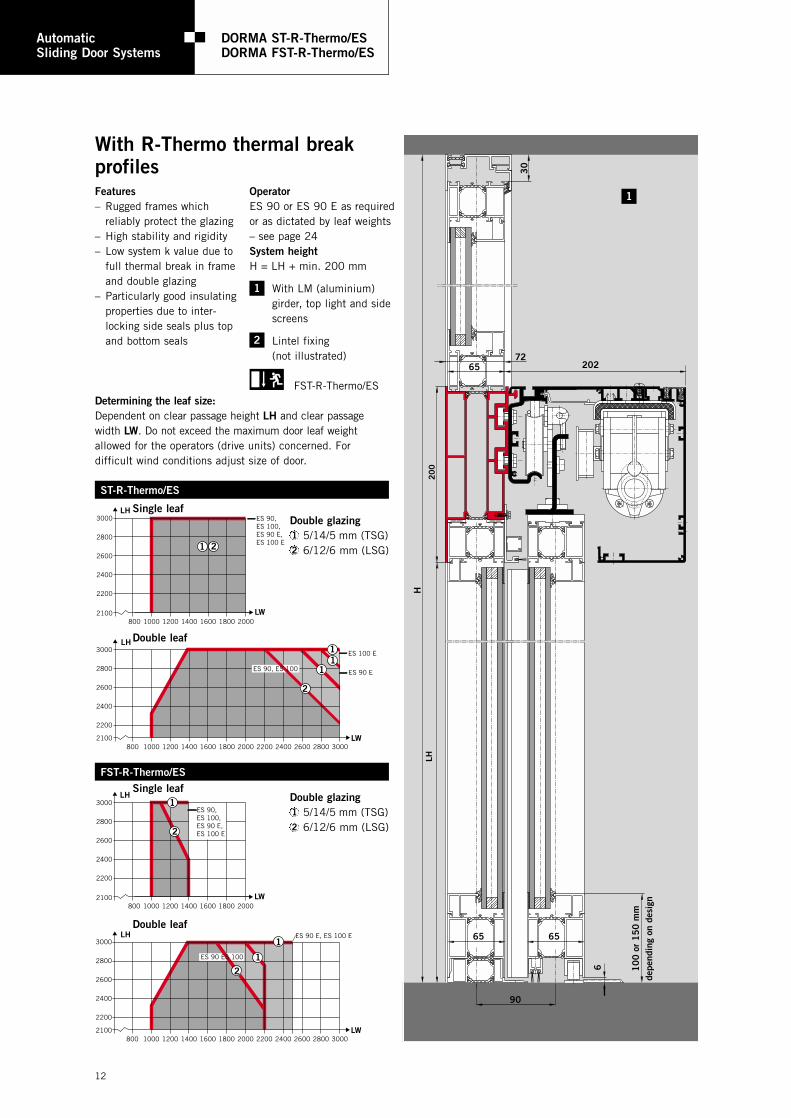
DORMA ST-R-Thermo/ESDORMA FST-R-Thermo/ES
12
90
202
H
30
20
0LH
10
0 o
r 1
50
mm
depe
ndin
g on
des
ign
6
65
65 65
72
With R-Thermo thermal breakprofiles
FST-R-Thermo/ES
Features– Rugged frames which
reliably protect the glazing– High stability and rigidity – Low system k value due to
full thermal break in frameand double glazing
– Particularly good insulatingproperties due to inter-locking side seals plus topand bottom seals
ST-R-Thermo/ES
FST-R-Thermo/ES
Double glazing1 5/14/5 mm (TSG)2 6/12/6 mm (LSG)
OperatorES 90 or ES 90 E as requiredor as dictated by leaf weights– see page 24System heightH = LH + min. 200 mm
With LM (aluminium) girder, top light and sidescreens
Lintel fixing (not illustrated)
ES 90,ES 100,ES 90 E,ES 100 E
3000
2800
2600
2400
2200
21001000800 1200 1400 1600 1800 2000 2200 2400 2600 2800 3000
LH
LW
2
1 ES 100 E
ES 90, ES 1001
1
3000
2800
2600
2400
2200
2100800 1000 1200 1400 1600 1800 2000
LH
LW
1 2
ES 90 E
3000
2800
2600
2400
2200
2100800 1000 1200 1400 1600 1800 2000
LH
LW
ES 90,ES 100,ES 90 E,ES 100 E
3000
2800
2600
2400
2200
21001000800 1200 1400 1600 1800 2000 2200 2400 2600 2800 3000
LH
LW
1
ES 90 E, ES 100 E
1
2
2
1ES 90 ES 100
Single leaf
Double leaf
Single leaf
Double leaf
2
1
1
Determining the leaf size:Dependent on clear passage height LH and clear passagewidth LW. Do not exceed the maximum door leaf weight allowed for the operators (drive units) concerned. For difficult wind conditions adjust size of door.
Double glazing1 5/14/5 mm (TSG)2 6/12/6 mm (LSG)

13
10
0
67
1
200*
max
. 8
mm
16
B1/B2
LW
25 5
25
max
. 8
Without side screens,without girder, with fixingto aluminium profiles ormasonry
With side screens
Without side screens,without girder, withfixing to masonry
System widthST-R-Thermo/ES FST-R-Thermo/ES1L B1 = 2 x LW + 272 mm B1 = 2 x LW + 272 mm
B2 = 2 x LW +122 mm B2 = 2 x LW + 150 mm2L B1 = 2 x LW +544 mm B1 = 2 x LW + 544 mm
B2 = 2 x LW +244 mm B2 = 2 x LW + 300 mm
B1: System width with 200 mm safety distanceB2: Without safety distance, with safety control software*only required if safety-software is not applied
Illustration shows "Heroal 065" profile series
Version -2 -1 0 1 2 3 4 5 6 7 8 9 10 11 12 13 14 15
LW 700 800 900 1000 1100 1200 1300 1400 1500 1600 1700 1800 1900 2000 2100 2200 2300 2400
DORMA ST-R-Thermo/ES
1L B1 1672 1872 2072 2272 2472 2672 2872 3072 3272 3472 3672 3872 4072 4272
1L B2 1522 1722 1922 2122 2322 2522 2722 2922 3122 3322 3522 3722 3922 4122
2L B1 2544 2744 2944 3144 3344 3544 3744 3944 4144 4344 4544 4744 4944 5144 5344
2L B2 2244 2444 2644 2844 3044 3244 3444 3644 3844 4044 4244 4444 4644 4844 5044
DORMA FST-R-Thermo/ES
1L B1 1672 1872 2072 2272 2472 2672 2872 3072
1L B2 1550 1750 1950 2150 2350 2550 2750 2950
2L B1 2544 2744 2944 3144 3344 3544 3744 3944 4144 4344 4544 4744 4944 5144 5344
2L B2 2300 2500 2700 2900 3100 3300 3500 3700 3900 4100 4300 4500 4700 4900 5100
Standard clear passage widths and system widths
16 17 18 19 20 21
2500 2600 2700 2800 2900 3000
5544 5744 5944 6144 6344 6544
5244 5444 5644 5844 6044 6244
5446
5544
5300
3
4
5

2500
2400
2300
2200
2100
2000800 1000 1250 1500 1750 2000
LH
LW
2500
2300
2400
2100
2200
2000
1900
18001000750 1250 1500 1750 2000 2250 2500 2750 3000 3250 3500 3750 4000
LH
LW
ES 90 TE
ES 90 T
2250 2500
1 2
1 2
14
Automatic TelescopicSliding Door Systems
DORMA TST-GDORMA FTST-G
20
0H
LH
280
min
. 5
0
RE30
8,5 5
3
min. 1204747
067
36
47
15 10
17
10
,5 53
With G-type fine frame profiles
FTST-G
Determining the leaf size:Dependent on clear passage height LH and clear passagewidth LW. Do not exceed the maximum door leaf weight allowed for the operators (drive units) concerned. For difficult wind conditions adjust size of door.
With LM (aluminium)girder, top light andside screens
Lintel fixing (not illustrated)
Floor guide without side screen
Features– Elegant all-glass
appearance due to slenderframe profiles
– High stability and rigidity– Protection against
draughts by side seals– Large clear passage widthOperatorES 90 T or ES 90 TE asrequired or as dictated byleaf weightsSystem heightH = LH + min. 200 mm
TST-G
One side (two leaves)
2500
2400
2300
2200
2100
2000900 1000 1250 1500 1750 2000
LH
LW
2500
2300
2400
2100
2200
2000
1900
18001000750 1250 1500 1750 2000 2250 2500 2750 3000 3250 3500 3750 4000
LH
LW
Technicallypossible
Emergency escapewidth range
2250 2400
1 2
1 2
FTST-G
One side (two leaves)
Both sides (two leaves each)
Both sides (two leaves each)
2
1
3
1
3
Glazing1 TSG 10 mm2 LSG 2 x 5 mm
Glazing1 TSG 10 mm2 LSG 2 x 5 mm

15
14
2
B
LW
5
LS
3028
(B-LW)/2 – 45
32 LW/4-6
LW/4-6
200
LSLS28
max
. 8
max
. 8
Version 1 2 3 4 5 6 7 8 9 10 11 12 13 14 15 16 17 18
LW 800 900 1000 1100 1200 1300 1400 1500 1600 1700 1800 1900 2000 2100 2200 2300 2400 2500
DORMA TST-G
2L B1 1428 1578 1728 1878 2028 2178 2328 2478 2628 2778 2928 3078 3228 3378 3528 3678 3828 3978
2L B2 1330 1480 1630 1780 1930 2080 2230 2380 2530 2680 2830 2980 3130 3280 3430 3580 3730 3880
4L B1 2556 2706 2856 3006 3156 3306 3456 3606 3756 3906 4056 4206
4L B2 2230 2380 2530 2680 2830 2980 3130 3280 3430 3580 3730 3880
DORMA FTST-G
2L B1 1428 1578 1728 1878 2028 2178 2328 2478 2628 2778 2928 3078 3228 3378 3528 3678 3828
2L B2 1330 1480 1630 1780 1930 2080 2230 2380 2530 2680 2830 2980 3130 3280 3430 3580 3730
4L B1 2556 2706 2856 3006 3156 3306 3456 3606 3756 3906 4056 4206
4L B2 2230 2380 2530 2680 2830 2980 3130 3280 3430 3580 3730 3880
Standard clear passage widths and system widths
With side screens
System widthTST-G FTST-G2L B1 = 3/2 LW + 228 mm B1 = 3/2 LW + 228 mm
B2 = 3/2 LW +130 mm B2 = 3/2 LW + 130 mm4L B1 = 3/2 LW +456 mm B1 = 3/2 LW + 456 mm
B2 = 3/2 LW +130 mm B2 = 3/2 LW + 130 mm
19 20 21 22 23 33
2600 2700 2800 2900 3000 4000
4356 4506 4656 4806 4956 6456
4030 4180 4330 4480 4630 6130
4356 4506 4656 4806 4956
4030 4180 4330 4480 4630
4
5
B1: System width with 200 mm safety distanceB2: Without safety distance, with safety control software
End of emergencyescape widthrange
This range is technically pos-sible but may not be allowed as emergency escape width
nm n
Without side screens,without girder, withfixing to aluminiumprofiles or masonry
Without side screens,without girder, withfixing to masonry
6

16
Automatic TelescopicSliding Door Systems
DORMA TST-G-IsoDORMA FTST-G-Iso
20
0H
LH
280
19
min
. 5
0
2332
34
RE30
8,5 70
min. 12048 48
36
With G-Iso double glazing fineframe profiles
FTST-G-Iso
With LM (aluminium)girder, top light andside screens
Lintel fixing (not illustrated)
Features– Elegant all-glass appearance
due to slender frame profiles– High stability and rigidity– Low k value with double
glazing– Particularly good insulating
properties due to inter-locking side seals plus topand bottom seals
– Large clear passage widthOperatorES 90 T or ES 90 TE as
required or as dictated byleaf weights
System heightH = LH + min. 200 mm
2
1
1
Determining the leaf size:Dependent on clear passage height LH and clear passagewidth LW. Do not exceed the maximum door leaf weight allowed for the operators (drive units) concerned. For difficult wind conditions adjust size of door.
2500
2400
2300
2200
2100
2000800 1000 1250 1500 1750 2000
LH
LW
2500
2300
2400
2100
2200
2000
1900
18001000750 1250 1500 1750 2000 2250 2500 2750 3000 3250 3500 3750 4000
LH
LW
ES 90 TE
ES 90 T
2250 2500
1 2 3
1 2 3
TST-G-Iso
One side (two leaves)
2500
2400
2300
2200
2100
2000900 1000 1250 1500 1750 2000
LH
LW
2500
2300
2400
2100
2200
2000
1900
18001000750 1250 1500 1750 2000 2250 2500 2750 3000 3250 3500 3750 4000
LH
LW
2250 2400
1 2 3
1 2 3Technically
possible
Emergency escapewidth range
FTST-G-Iso
One side (two leaves)
Both sides (two leaves each)
Both sides (two leaves each)
Double glazing1 4/12/4 mm2 5/10/5 mm3 6/8/6 mm
Double glazing1 4/12/4 mm2 5/10/5 mm3 6/8/6 mm

17
max
. 8
min.5
min. 20068
LW/4 –10
LW/4 + 63
43 41,5
4075
B1/B2
LW
max
. 8
max
. 8
max
. 8
36
75LW
15
54
With sidescreens
Without side screens, without girder, with fixing to aluminiumprofiles or masonry
System widthTST-G-Iso FTST-G-Iso2L B1 = 3/2 LW +310 mm B1 = 3/2 LW + 310 mm
B2 = 3/2 LW +155 mm B2 = 3/2 LW + 155 mm4L B1 = 3/2 LW +620 mm B1 = 3/2 LW + 620 mm
B2 = 3/2 LW +310 mm B2 = 3/2 LW + 310 mm
B1: System width with 200 mm safety distanceB2: Without safety distance, with safety control software
4
5
Version 1 2 3 4 5 6 7 8 9 10 11 12 13 14 15 16 17 18
LW 800 900 1000 1100 1200 1300 1400 1500 1600 1700 1800 1900 2000 2100 2200 2300 2400 2500
DORMA TST-G-Iso
2L B1 1510 1660 1810 1960 2110 2260 2410 2560 2710 2860 3010 3160 3310 3460 3610 3760 3910 4060
2L B2 1355 1505 1655 1805 1955 2105 2255 2405 2555 2705 2855 3005 3155 3305 3455 3605 3755 3905
4L B1 2720 2870 3020 3170 3320 3470 3620 3770 3920 4070 4220 4370
4L B2 2410 2560 2710 2860 3010 3160 3310 3460 3610 3760 3910 4060
DORMA FTST-G-Iso
2L B1 1510 1660 1810 1960 2110 2260 2410 2560 2710 2860 3010 3160 3310 3460 3610 3760 3910 4060
2L B2 1355 1505 1655 1805 1955 2105 2255 2405 2555 2705 2855 3005 3155 3305 3455 3605 3755 3905
4L B1 2720 2870 3020 3170 3320 3470 3620 3770 3920 4070 4220 4370
4L B2 2410 2560 2710 2860 3010 3160 3310 3460 3610 3760 3910 4060
Standard clear passage widths and system widths
19 20 21 22 23 33
2600 2700 2800 2900 3000 4000
4520 4670 4820 4970 5120 6620
4210 4360 4510 4660 4810 6310
4520 4670 4820 4970 5120
4210 4360 4510 4660 4810
End of emergencyescape widthrange
This range is technically pos-sible but may not be allowed as emergency escape width
nm n

18
Automatic TelescopicSliding Door Systems
DORMA TST-RDORMA FTST-R
Features– Rugged frames which
reliably protect the glazing– High stability and rigidity – Protection against
draughts due to inter-locking side seals
– Large clear passage width
OperatorES 90 T or ES 90 TE asrequired or as dictated byleaf weights
System heightH = LH + min. 200 mm
20
0H
LH
min
. 5
0
RE30
min. 130
6
15
0
171 109,5 36 36
25
With R-type standard frame profiles
FTST-R
With LM (aluminium)girder, top light and sidescreens, or with MSHsteel hollow section girder (not illustrated)
Lintel fixing (not illustrated)
2
1
1
Determining the leaf size:Dependent on clear passage height LH and clear passagewidth LW. Do not exceed the maximum door leaf weightallowed for the operators (drive units) concerned. For difficult wind conditions adjust size of door.
2500
2400
2300
2200
2100
2000800 1000 1250 1500 1750 2000
LH
LW
2500
2300
2400
2100
2200
2000
1900
18001000750 1250 1500 1750 2000 2250 2500 2750 3000 3250 3500 3750 4000
LH
LW
ES 90 TE
ES 90 T
2250 2500
1 2 3 4
1 2 3 4
TST-R
One side (two leaves)
2500
2400
2300
2200
2100
2000900 1000 1250 1500 1750 2000
LH
LW
2500
2300
2400
2100
2200
2000
1900
18001000750 1250 1500 1750 2000 2250 2500 2750 3000 3250 3500 3750 4000
LH
LW
2250 2400
1 2 3 4
1 2 3 4
Technicallypossible
Emergency escapewidth range
FTST-R
One side (two leaves)
Both sides (two leaves each)
Both sides (two leaves each)
Glazing
1 TSG, LSG, 6 mm
2 TSG, LSG, 8 mm
3 TSG, LSG, 10 mm
4 LSG 9 mm, A1
Glazing
1 TSG, LSG, 6 mm
2 TSG, LSG, 8 mm
3 TSG, LSG, 10 mm
4 LSG 9 mm, A1

19
5
105
72
100 min. 200
77
LS
LW
B1 / B2
68 72 10
72
8
-0
.5
724
max
. 8
max
. 8
max
. 8m
ax. 8
LS
LS
max
. 8
max
. 8
10
0
18
105LW
With side screens
System widthTST-R FTST-R2L B1 = 3/2 LW +370 mm B1 = 3/2 LW + 370 mm
B2 = 3/2 LW +190 mm B2 = 3/2 LW + 190 mm4L B1 = 3/2 LW +740 mm B1 = 3/2 LW + 740 mm
B2 = 3/2 LW +380 mm B2 = 3/2 LW + 380 mm
B1: System width with 200 mm safety distanceB2: Without safety distance, with safety control software
4
Version 1 2 3 4 5 6 7 8 9 10 11 12 13 14 15 16 17 18
LW 800 900 1000 1100 1200 1300 1400 1500 1600 1700 1800 1900 2000 2100 2200 2300 2400 2500
DORMA TST-R
2L B1 1570 1720 1870 2020 2170 2320 2470 2620 2770 2920 3070 3220 3370 3520 3670 3820 3970 4120
2L B2 1390 1540 1690 1840 1990 2140 2290 2440 2590 2740 2890 3040 3190 3340 3490 3640 3790 3940
4L B1 2840 2990 3140 3290 3440 3590 3740 3890 4040 4190 4340 4490
4L B2 2480 2630 2780 2930 3080 3230 3380 3530 3680 3830 3980 4130
DORMA FTST-R
2L B1 1570 1720 1870 2020 2170 2320 2470 2620 2770 2920 3070 3220 3370 3520 3670 3820 3970
2L B2 1390 1540 1690 1840 1990 2140 2290 2440 2590 2740 2890 3040 3190 3340 3490 3640 3790
4L B1 2840 2990 3140 3290 3440 3590 3740 3890 4040 4190 4340 4490
4L B2 2480 2630 2780 2930 3080 3230 3380 3530 3680 3830 3980 4130
Standard clear passage widths and system widths
19 20 21 22 23 33
2600 2700 2800 2900 3000 4000
4640 4790 4940 5090 5240 6740
4280 4430 4580 4730 4880 6380
4640 4790 4940 5090 5240
4280 4430 4580 4730 4880
End of emergencyescape widthrange
nm n
Without side screens,without girder, with fixingto aluminium profiles ormasonry
Without side screens,without girder, withfixing to masonry
5
6
This range is technically pos-sible but may not be allowed as emergency escape width

AutomaticSliding Door Systems
DORMA ST-R/ES and ST-G-Iso/ES with automaticconcealed-rod locking
20
12
3
4
5
In their double leaf version,DORMA sliding door systemsof the ST/ES design with R-type standard frame profilesor with G-Iso fine frame profiles for double glazingcome with the option of anautomatic concealed-rodlocking system. The lockingrods of high-strength steelare integrated out of sight inthe centre seal profiles.
In the locked condition, therods extend to engage bothin high-strength keeps located in the transom construction and in bushing-type keeps recessed in thefloor. This four-point lockingsystem ensures maximumresistance against all attemptsto force the sliding panelsopen.
The locking and unlockingoperations are performed bymeans of an electric motorintegrated in the transomassembly.
In the event of a power failure or in emergencysituations, the sliding leavescan be manually locked and unlocked by means of a lever mechanism. Thelocking system can only beunlocked from the outsideby an authorised opening signal. The system can beequipped with an audible orvisual locking indicator trig-gered via a floating contact.The bushing-type keepsrecessed in the floor are provided with spring-loadedcovers to protect them
against dirt and contamina-tion when the door isunlocked, and are easy toclean.
For emergency exits andescape routesA model suitable for employ-ment in emergency escaperoutes is also available.
DORMA ST-R/ES with concealed-rod multipoint locking system
High stability plus optimum protection

21
36 202
20
45
7979
52
17
4
Electric drive unit for locking and unlocking
Top keep
Concealed locking rods
Floor keep
Manual unlocking device
1
2
1
3
4
5
2
3
4
33
53 53
35
48
17
max. 30
20
46
171
10
Electric drive unit for locking and unlocking
Top keep
Concealed locking rods
Floor keep
Manual unlocking device
1
2
1
3
4
5
2
3
4
33
ST-G-Iso/ES with concealed-rod locking system ST-R/ES with concealed-rod locking system

AutomaticSliding Door Systems
DORMA ST-R/ES and ST-G-Iso/ES with automaticconcealed-rod locking
22
Features and benefits
Light barrier Light barrier16 A
3 x
1.5
mm
2
Control unit
Motor
4 x 0.14 mm2 each – included in standard DORMA equipment
2 x
0.6
mm
2
2 x
0.6
mm
2
6 x
0.6
mm
2
2 x
0.8
mm
2
8 x
0.6
mm
2
34 5 6
7 9
12
2 x
0.8
mm
2
+–
8
FST-R/ES with concealed-rod multipoint locking system – Connections
– High level of security protection
– Solves the age-old contradiction:Locked against ingress,but openable from theinside
– No impairment to thevisual attractiveness ofthe door
– Designed and manufacturedin accordance with thelatest state of the art and in line with all relevant standards andspecifications.
1 Motion detector – internal, external2 Locking system3 Power supply: 230 V, 50/60 Hz
(Illustration shows FST/ES model with cable lead-in fromthe right; ST/ES model: cable lead-in from the left)
4 Emergency stop pushbutton to be installed next to door; cable length max. 100 m. Recommendedheight of installation 0.98 – 1.05 m.
5 Key switch for activating the locking system (only FST/ESwhere used in emergency exits and escape routes)
6 Program switch, cable length max. 100 m; where installed with other lines, provide with shield
7 Key switch, code card reader with floating contact orsimilar, external
8 Blind cable for external power supply 24 V DC9 Pushbutton, internal

23
12
18
95
0
20
21
30
65
50 7
65
10
14
14
R3
19
0
22
3
R4
20
55 85
22
10862
3 2
4
2
1
3
AutomaticSliding Door Systems
Locks forDORMA ST/ES, TSTDORMA FST/ES, FTST
1
2
3
4
3
*
In-transom electro-mechanical dual-actionhook lock; with manualunlocking for FST/ESand FTST/ES (not illustrated)
Hook lock; for ST-R/ES,FST-R/ES and TST-R,FTST-R sliding doorsonly
Floor locks
Automatic concealed-rod multipoint lockingsystem; for ST-R/ES,FST-R/ES, ST-G-Iso/ESand FST-G-Iso/ES sliding doors only (see pages 20 – 22)
Lock options
2
1 3
4

2524
AutomaticSliding Door Systems
DORMA ES, ES E
Operator types
17136
20
0
DORMA ES 90
1 Standard operator withlow-noise track rail
202
20
0
36
DORMA ES 90 E
2 Standard operator withlow-noise track rail,sound-insulated motormounting and increasedmotor capacity
20
0
17136
DORMA ES 100
3 Enhanced operator withlow-noise, replaceabletrack rail
202
20
0
36
DORMA ES 100 E
4 Enhanced operator withsound-insulated motormounting, low-noise,replaceable track rail andincreased motor capacity
4
7
20
0
17136
Additional equipment 2 Expansion module EM52 Self-monitoring functions for all main components2 Electro-magnetic clutch2 Rubber rope as redundant energy source2 Self-monitoring radar motion detector in the escape direction
20
0
17136
DORMA ES 90-FST
FST operators for sliding doors in emergency exits and escape routes
20
0
17136
DORMA ES 90 E-FST DORMA ES 100-FST
20
0
17136
DORMA ES 100 E-FST
Components (Illustration shows ES 90/ES 100)
1 Track and mounting profile2 Carrier3 Door suspension device with adjustable fixture4 Motor with decoder5 Track rail6 Return pulley7 Basic module, control with integrated switched power
supply unit and multi-way connectors for optionalexpansion modules
8 Door stop
56
2
38
1
5 Standard operator withlow-noise track rail
6 Standard operator withlow-noise track rail,sound-insulated motormounting and increasedmotor capacity
7 Enhanced operator withlow-noise, replaceabletrack rail
8 Enhanced operator withsound-insulated motormounting, low-noise,replaceable track rail and increased motor capacity

AutomaticSliding Door Systems
Accessories
26
Door frame profilesHand terminal
– Program selection– Indication of the current
program– Adjustment of basic
parameters– CP 90 C with timer function– CP 90 N for night-bank
mode (additional to CP 90or CP 90 C)
– Display of error codes forremote diagnostics
– Available in black, whiteand silver
– Dimensions (W x H)48 mm x 125 mm
– Suitable for ST/ES and TST
– External installation– Concealed or surface-
mounted units– Lockable/Rotary knob– Suitable for standard
flush-type boxes– Can be integrated with an
emergency-stop switch ina double frame
– Key switches concealed orsurface-mounted
– Eagle system– Directionally sensitive or
standard model– Any combination of radar
heads– No official licence fees
(in most countries)– No effect on pacemakers
with a very low output ofjust approx. 2 mW
– No interference frommobile phones
– Concealed and surface-mounted
– Stainless steel finishes– Water-resistant models– Keypads for access
control systems
– Fast and problem-freecommissioning of DORMAsliding doors
– Adjustment of basic parameters
– Simple and reliable diagnostics in the event ofmalfunctions
– Plain text display
Fine frame safety glassprofile systemDORMA ST-G, FST-G,TST-G, FTST-G
Fine frame double glazing profile systemDORMA ST-G-Iso, FST-G-Iso,TST-G-Iso, FTST-G-Iso
CP 90 program selector Switches/PushbuttonsRadar motion detectorsProgram switches
Standard frame profile systemDORMA ST-R, FST-R, TST-R, FTST-R
Thermal break profile systemST-R-Thermo, FST-R-Thermo(not illustrated)

27
AutomaticSliding Door Systems
DORMA TSTDORMA FTST
Automatic telescopic sliding door system with( ) 4 sliding leaves (standard) ( ) 2 sliding leaves( ) 2 side screens ( ) 1 side screen( ) without side screens( ) with safety control software ( ) Top light
( ) 1-piece ( ) 2-piece ( ) 3-piece( ) Solid top panel( ) FTST approved for emergency exits and escape routes
Manufactured in accordance with German guidelines for power-operated windows, doors and gates, ZH 1/494, German UVV (accidentprevention) regulations and VDE (German Association of ElectricalEngineers) standards, latest edition in each case. Type-approved by the German Technical Inspectorate (TÜV); tested and approved in accordance with EU low-voltage directives; manufactured on thebasis of a quality management system registered to ISO 9000.
Power supply: 230 V, 50/60 Hz
Design:( ) Fine frame (toughened glass) profiles, G( ) Double glazing fine frame profiles, G-Iso( ) Standard frame profiles, R
Transom construction:( ) LM (aluminium) girder, self-supporting up to 4000 mm( ) LM (aluminium) girder, side screen supported, up to 6600 mm,( ) including cover( ) MSH girder (non-standard)
Installation:( ) Corridor (passage) ( ) Wall (face-fix)
Floor guide:( ) Floor surface guide without floor track (standard)( ) Concealed guide with floor track
Sliding leaf glazing:( ) Toughened safety glass (TSG)... ( ) Laminated safety glass (LSG)...( ) Double glazing ... ( ) Special glass .....................( ) Adhesive-bonded midrails
Side screen glazing:( ) Toughened safety glass (TSG)... ( ) Laminated safety glass (LSG)...( ) Double glazing ... ( ) Special glass .....................( ) Adhesive-bonded midrails
Top light glazing:( ) Float glass ... ( ) Toughened safety glass (TSG) ...( ) Laminated safety glass (LSG)... ( ) Double glazing ...( ) Special glass ........................
Operator drive and control unit, TST:Automatic sliding door operator of modular design( ) ES 90 T ( ) ES 90 TE
Integrated microprocessor control, self-learning, with adjustableparameters for opening and closing speed, hold-open time and alsoopening and closing force. With pulse expansion for cheque card/code card reader or key switch. With RS 485 interface, connectionfor access control system, bell contact and battery pack. Degree ofprotection IP 20.
( ) Fail-safe (standard) [opens when de-energised]( ) Fail-secure [closes when de-energised]( ) Connection for airlock control( ) Door status signal( ) Module for connection to EIB building control system( ) Emergency power module (UPS)
Specification text Operator drive and control unit, FTST:Automatic sliding door operator of modular design( ) ES 90 T-FST ( ) ES 90 TE-FST
With self-diagnostics of the microprocessor control and integratedEM5 expansion module for redundant monitoring of opening safety.Self-learning, with adjustable parameters for opening and closingspeed, hold-open time and also opening and closing force. Fail-safe(opens when de-energised). With pulse expansion for cheque card/code card reader or key switch. With RS 485 interface, connection for access control system, bell contact and battery pack. Degree ofprotection IP 20.
( ) Door status signal( ) Module for connection to EIB building control system( ) Emergency power module (UPS)
Function programs:Off; Automatic; Permanent open; Partial opening; Exit only; Self-regu-lating partial opening; Exit only, partial opening; Night-bank control
Safety devices:Automatic obstruction detection; automatic reversing cycle; forcelimitation; emergency stop pushbutton; integrated safety light barriers for presence monitoring
Switches, pushbuttons, external:Program switch( ) lockable (FTST) ( ) non-lockable (not for FTST)( ) concealed ( ) surface-mountedEmergency stop pushbutton, external:( ) lockable ( ) non-lockable( ) concealed ( ) surface-mounted ( ) with emergency break glass
( ) Electronic program selector, surface-mounted (TST only)( ) CP 90 ( ) CP 90 C (with timer function)( ) CP 90 N (for night-bank control,
additional to CP 90 or CP 90 C)
Locking system:( ) Electro-mechanical lock, including manual unlocking( ) Mechanical lock
Activators:( ) Eagle 1 radar motion detector, directionally sensitive, ... units( ) Eagle 2 radar motion detector, non-directionally sensitive, ... units( ) Eagle 3 radar motion detector, self-monitoring, ... units
(for FST/ES)( ) Other: ........, ........ units
Finish for aluminium parts:( ) silver anodised (Eloxal EV6/C0)( ) dark-brown anodised (Eloxal EV6/C34)( ) RAL ...................... ( ) Special colour ........................
System dimensions:Total width B ............... mm Clear passage width LW .......... mmTotal height H ............... mm Clear passage height LH .......... mm
Make:( ) DORMA TST( ) DORMA FTST

AutomaticSliding Door Systems
DORMA ST/ESDORMA FST/ES
WN 051 958, 1/01, ST-TST, GB, XX. DD/CtP. 1/01
Subject to change without notice DORMA GmbH + Co. KGP.O. Box 400958247 EnnepetalGermanyTel. +49(0)2333/793-0Fax +49(0)2333/79 34 95www.dorma.com
Automatic sliding door with( ) 2 sliding leaves (standard) ( ) 1 sliding leaf( ) 2 side screens ( ) 1 side screen( ) without side screens( ) 2 hinged safety pocket screens ( ) 1 hinged safety pocket screen( ) with safety control software (without hinged safety pocket screens)( ) Top light
( ) 1-piece ( ) 2-piece ( ) 3-piece( ) Solid top panel( ) FST/ES approved for emergency exits and escape routes
Manufactured in accordance with German guidelines for power-operated windows, doors and gates, ZH 1/494, German UVV (accidentprevention) regulations and VDE (German Association of ElectricalEngineers) standards, latest edition in each case. Type-approved by the German Technical Inspectorate (TÜV); tested and approved in accordance with EU low-voltage directives; manufactured on thebasis of a quality management system registered to ISO 9000.
Power supply: 230 V, 50/60 Hz
Design:( ) Fine frame (toughened glass) profiles, G( ) Fine frame double glazing profiles, G-Iso( ) Standard frame profiles, R ( ) Thermal break profiles, R-Thermo
Transom construction:( ) LM (aluminium) girder, self-supporting up to 4000 mm( ) LM (aluminium) girder, side screen supported, up to 6600 mm,
including cover( ) MSH girder (non-standard)
Installation:( ) Corridor (passage) ( ) Wall (face-fix)
Floor guide:( ) Floor surface guide without floor track (standard)( ) Concealed guide with floor track
Sliding leaf glazing:( ) Toughened safety glass (TSG)... ( ) Laminated safety glass (LSG)...( ) Double glazing ... ( ) Special glass ......................( ) Adhesive-bonded midrails
Side screen glazing:( ) Toughened safety glass (TSG)... ( ) Laminated safety glass (LSG)...( ) Double glazing ... ( ) Special glass ......................( ) Adhesive-bonded midrails
Hinged safety pocket screen glazing( ) Toughened safety glass (TSG)... ( ) Laminated safety glass (LSG)...( ) Double glazing ... ( ) Special glass ......................( ) Adhesive-bonded midrails
Top light glazing:( ) Float glass ... ( ) Toughened safety glass (TSG)...( ) Laminated safety glass (LSG)... ( ) Double glazing ...................( ) Special glass ......................
Operator drive and control unit, ST/ES:Automatic sliding door operator of modular design( ) ES 90 ( ) ES 90 E( ) ES 100 ( ) ES 100 E
Integrated microprocessor control, self-learning, with adjustableparameters for opening and closing speed, hold-open time and alsoopening and closing force. With pulse expansion for cheque card/code card reader or key switch. With RS 485 interface, connectionfor access control system, bell contact and battery pack. Degree ofprotection IP 20.
Specification text ( ) Fail-safe (standard) [opens when de-energised]( ) Fail-secure [closes when de-energised]( ) Connection for airlock control( ) Door status signal( ) Module for connection to EIB building control system( ) Emergency power module (UPS)
Operator drive and control unit, FST/ES:Automatic sliding door operator of modular design( ) ES 90-FST ( ) ES 90 E-FST( ) ES 100-FST ( ) ES 100 E-FST
With self-diagnostics of the microprocessor control and integratedEM5 expansion module for redundant monitoring of opening safety,plus redundant power source. Self-learning, with adjustable parameters for opening and closing speed, hold-open time and alsoopening and closing force. Fail-safe (opens when de-energised). With pulse expansion for cheque card/code card reader or key switch.With RS 485 interface, connection for access control system, bellcontact and battery pack. Degree of protection IP 20.
( ) Door status signal( ) Module for connection to EIB building control system( ) Emergency power module (UPS)
Function programs:Off; Automatic; Permanent open; Partial opening; Exit only; Self-regu-lating partial opening; Exit only, partial opening; Night-bank control
Safety devices:Automatic obstruction detection; automatic reversing cycle; forcelimitation; emergency stop pushbutton; integrated safety light barriers for presence monitoring
Switches, pushbuttons, external:Program switch( ) lockable (FST/ES) ( ) non-lockable (not for FST/ES)( ) concealed ( ) surface-mounted
Emergency stop pushbutton, external:( ) lockable ( ) non-lockable( ) concealed ( ) surface-mounted ( ) with emergency break glass
( ) Electronic program selector, surface-mounted (ST/ES only)( ) CP 90 ( ) CP 90 C (with timer function)( ) CP 90 N (for night-bank control, additional to CP 90 or CP 90 C)
Locking system:( ) Electro-mechanical lock, including manual unlocking( ) Mechanical lock (not FST/ES)( ) Automatic concealed-rod multipoint locking
Activators:( ) Eagle 1 radar motion detector, directionally sensitive, ... units( ) Eagle 2 radar motion detector, non-directionally sensitive, ... units( ) Eagle 3 radar motion detector, self-monitoring, ... units
(for FST/ES)( ) Other: ........, ........ units
Finish for aluminium parts:( ) silver anodised (Eloxal EV6/C0)( ) dark-brown anodised (Eloxal EV6/C34)( ) RAL ...................... ( ) Special colour ........................
System dimensions:Total width B ............... mm Clear passage width LW .......... mmTotal height H ............... mm Clear passage height LH .......... mm
Make:( ) DORMA ST/ES( ) DORMA FST/ES
Top Related