


Languages
Pages
Legal


www.fine-tek.com
Monitoring Devices For Conveyor System

Switching Capacity
1
This device monitors the operation process for potentially hazardous conditions and activate an alarm when it is occurred misalignment, the SRT series conveyor belt misalignment switch protects the conveyor belt from damage due to belt misalignment or run off。For normal condition, the belt misalignment switches are generally mounted on both sides and the edge of the conveyor belt。A small clearance between the contact rollers and a little swaying for the belt edges are allowable. When the swaying exceeds the normal limit (on/ about 20 mm), the belt edge pushes the contact roller, which drives the switch and operates the contacts, the misalignment switch will reset automatically when the belt resumes normal running. These control devices are used in pair on both side of conveyor belt detected place, each unit can be equipped with two micro-switches to produce signals indicating the belt misalignment at two deviation points。The first signal point could indicate small belt deviation by output an alarm, the second signal point could guard against extreme belt run off by shutting down the conveyor。The roller is adjustable up to 20 in both directions and is positioned approximately 20mm from the conveyor belt , the switch actuation points are adjustable from 0 to 35 by a simple change of the actuating cams。
°
° °
APPLICATIONS
Conventional Belt ConveyorsUnderground, Cable Supported Belt ConveyorsStacker / Reclaimer Conveyors Ship Loading / Unloading SystemsTripper and Shuttle ConveyorsCrane / Shovel Boom Position Limit DetectorApron Feeders & ConveyorsHeavy Duty Limit Switch
CHARACTERSEasy Installation, operation sensitive Roller arm can move up to 75 degrees in either directionDust tight, IP 67 weatherproof, Die cast aluminum housingRoller lever actuating angle 20 for alarm signal and 35° for shutting down systemTo Save Process downtime, product loss and replacing cost of damaged conveyor belt
°
CONVEYOR BELT MISALIGNMENT SWITCHFOR PROTECTION OF BELT CONVEYORS AND PERSONNEL
-20~60BC
IP67
Approx. 2.9kg
Auto
Die cast ADC
15A,125/250 Vac 1/2A 125 Vdc SPDTx2
3.4~5.4N.m (0.35~0.55kgf.m)
SRT
SPECIFICATION
Reset Way
Ambient Temp.
Enclosure Protection Grade
Enclosure Material
Weight
Action Force
DIMENSION
SRT

2
CHARACTERS
Universal design for bi-direction activation Compact design for tight-fit areas, IP67 rugged die cast aluminum housing Manual reset lever Easily orientated at either end or intermediate position in pull cable run Cable Pull 30° for shutting down system Highly visible black arm easily shows condition of the switch, indicating alarm or normal
Belt conveyor safety cable pull switches are designed for providing a switching system to isolate the power to conveyor system and other equivalent process equipment in the emergency condition。The cable pull switches are actuated by a plastic coated steel wire, which are placed along-side the conveyor。When you pull on the cable at any point, it will trip and automatically lock the switches, deenergizing the conveyor starter contactor。Each switch is bi-directional in operation and has two cable fitted to it from opposite directions terminated with a spring at the anchor points, please see drawing 4 the springs will operate the switch on cable breakage。After tripping the mechanical latch can be released only on the switch itself by the reset lever。
APPLICATIONSemergency or normal stop for below facilities
Conventional Belt ConveyorsShuttle ConveyorsBucket ElevatorsPackaging Lines Stockpile/Reclaim systems, Cranes, Shovels, DraglinesShip Loading / Unloading SystemHorizontal Feed Systems
SAFETY CABLE PULL SWITCHFOR EMERGENCY OR NORMAL SHUT-OFF
SRS
-20~60BC
IP67
Approx. 2.9kg
Manual
Die cast ADC
49A9.8n (5A1kgf.m)
SPECIFICATION
Switching Capacity
Reset Way
Ambient Temp.
Enclosure Protection Grade
Enclosure Material
Weight
Action Force
DIMENSION
15A,125/250 Vac 1/2A 125 Vdc SPDTx2
SRS

FEATURES
3
SPEED MONITOR
Maximum monitoring range 1~999rpm.
7-seg led display 0~999
Alarm monitoring: low speed, stop, reverse,
blackout and overload.
Start up delay function allow motor to run up
gradually.
Alarm delay function can avoid fault alarm which
many caused by temporary slow down or load
changed.
Selectable rotate direction for both CCW and
CW makes installation more versatile.
Light pulses are not affected by environmental
conditions.
Complementary to FineTek PB/PM series digital
Panel meter to indicate speed.
DIMENSIONS:
Special Function (built in function)
4~20mA output, proportional to selectable speed range like 100rpm, 200rpm, 500rpm and 1,000rpm.
ED4000(SM4) Speed Monitor is a totally new rotational speed monitoring equipment; it uses the principle of photo detector and microprocessor to accurately calculate a wide range of rotational speed. It detects rang 1~999rpm and the rotational speed display on 7-seg led.There is a contact relay that could be used either for alarm or control purposes during the monitoring process. The alarm set point could be directly set by numerical knobs which is more convenient and more accurate than conventional means. It comes equipped with analog signal output which could be utilized for various display indications and more precise control. It is ideal for applications in monitoring low speed, stop and overload situations.
APPLICATIONLow speed and overload protection monitoring of various conveyer systems
Networked circuits to form sequential start or stop
Frequently used macstorage bucket elevators and belt conveyer machines
hines: Grain and coal
SPECIFICATION
Measuring Range:0~999 rpm.
7-seg led display 0~999
Alarm Set point:1~1999 rpm by rotary switch.
Alarm Conditions:Underspeed, standstill,
power failure.
Startup Delay:0 second or 15 Seconds. Selectable
Alarm Contact Rating:SPDT 5A/250Vac.
Alarm Delay:0, 3, 6, 9,...,27 seconds. Selectable
Speed Analog Output:4~20mA
(Signal Range Selectable:100/200/500/1000rpm).
Power Supply:85~265Vac, 50/60Hz
Power Consumption:6VA.
Operating Temperature: -20BC~70BC.
Housing:Cast Aluminum.
Protection:IP65
Cable Entry:1/2"NPT X 2 hole.
ED4000
Minimum space
160
f113
1/2"NPT 40
100
130 12
12.5
12.5
60
42
58
11
50
f23
(Unit:mm)Install clockwise
Install counter-clockwise
Inertial roller
Belt
3/8" or M10 Screw hole
3/8" or M10screw
EDA-1050Copper connector
EDA-1090Flexible rubber tube
Speed monitor
Metal cable tie Metal cable tie
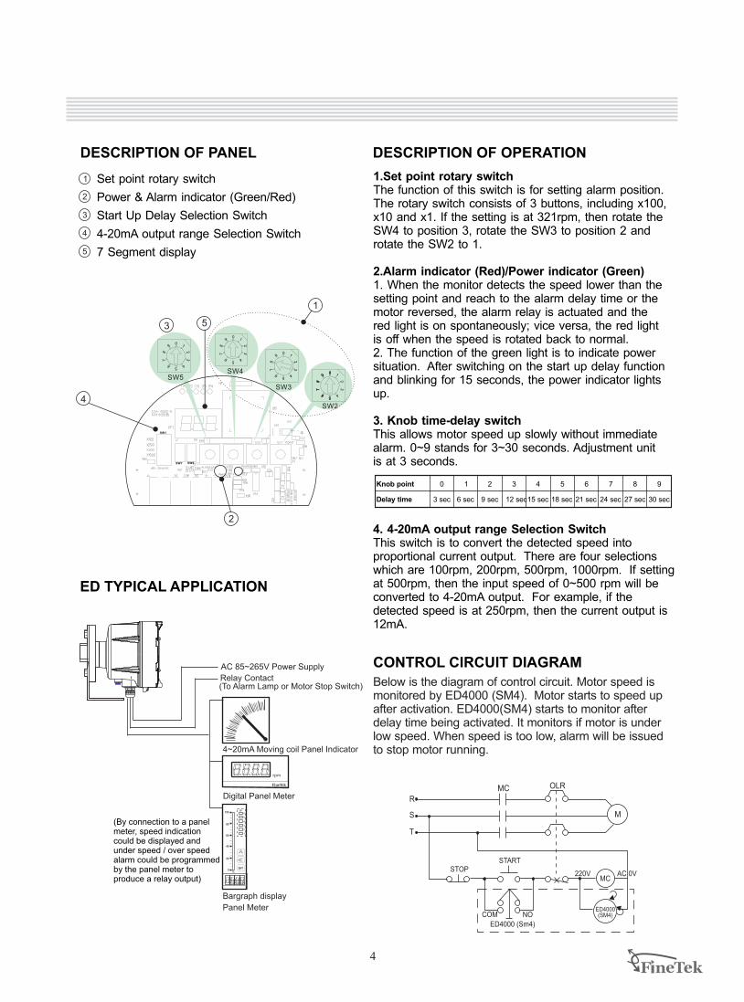
DESCRIPTION OF PANEL
1
2
3
4
5
1.Set point rotary switchThe function of this switch is for setting alarm position. The rotary switch consists of 3 buttons, including x100, x10 and x1. If the setting is at 321rpm, then rotate the SW4 to position 3, rotate the SW3 to position 2 and rotate the SW2 to 1.
2.Alarm indicator (Red)/Power indicator (Green)1. When the monitor detects the speed lower than the setting point and reach to the alarm delay time or the motor reversed, the alarm relay is actuated and the red light is on spontaneously; vice versa, the red light is off when the speed is rotated back to normal. 2. The function of the green light is to indicate power situation. After switching on the start up delay function and blinking for 15 seconds, the power indicator lights up.
3. Knob time-delay switchThis allows motor speed up slowly without immediate alarm. 0~9 stands for 3~30 seconds. Adjustment unit is at 3 seconds.
4. 4-20mA output range Selection SwitchThis switch is to convert the detected speed into proportional current output. There are four selections which are 100rpm, 200rpm, 500rpm, 1000rpm. If setting at 500rpm, then the input speed of 0~500 rpm will be converted to 4-20mA output. For example, if the detected speed is at 250rpm, then the current output is 12mA.
Knob point 1 3 5 7 9
Delay time 3 sec 6 sec 9 sec 12 sec15 sec 18 sec 21 sec 24 sec 27 sec 30 sec
0 4 6 82
4
Set point rotary switch
Power & Alarm indicator (Green/Red)
Start Up Delay Selection Switch
4-20mA output range Selection Switch
7 Segment display
DESCRIPTION OF OPERATION
ED TYPICAL APPLICATION
CONTROL CIRCUIT DIAGRAMAC 85~265V Power Supply
%
SP
1
2
3
4
5
6
4~20mA Moving coil Panel Indicator
Digital Panel Meter
Bargraph display
Panel Meter
(To Alarm Lamp or Motor Stop Switch)Relay Contact
(By connection to a panel meter, speed indication could be displayed and under speed / over speed alarm could be programmed by the panel meter to produce a relay output)
rpm
R
T
S
OLRMC
START
ED4000 (Sm4)
STOP
ED4000(SM4)COM NO
220VMC
M
AC 0V
Below is the diagram of control circuit. Motor speed is monitored by ED4000 (SM4). Motor starts to speed up after activation. ED4000(SM4) starts to monitor after delay time being activated. It monitors if motor is under low speed. When speed is too low, alarm will be issued to stop motor running.
2
4
32
1
SW2
4
32
1
SW1
SW7 SW6
09
87
6 54
32
1
SW5
09
87
6 54
32
1
SW4 09
87
6 5
09
87
6 54
32
1
SW3
9
87
6 54
32
0 1
9
87
6 54
32
0 1
9
87
6 5
0
4
1
3 5

Global Network
Taiwan -
No.16, Tzuchiang St., Tucheng Industrial Park New Taipei City 236, TaiwanTEL: 886-2-2269-6789FAX: 886-2-2268-6682EMAIL: [email protected]
FINETEK CO., LTD. - I-Lan FactoryTEL: 886-3-990-9669FAX: 886-3-9909659
FINETEK CO., LTD. - Taichung BranceTEL: 886-4-2337-0825FAX: 886-4-2337-0836
FINETEK CO., LTD. - Kaohsiung BranchTEL: 886-7-333-6968 FAX: 886-7-536-8758
China FINE AUTOMATION CO., LTD. - Shanghai FactoryNo.451 DuHui Rd, MinHang District, Shanghai, China 201109TEL: 86-21-6490-7260FAX: 86-21-6490-7276EMAIL: [email protected]
SingaporeFINETEK PTE LTD. - Singapore OfficeNo. 60 Kaki Bukit Place, #07-06 Eunos Techpark 2 Lobby B, Singapore 415979TEL: 65-6452-6340FAX: 65-6734-1878EMAIL: [email protected]
FINETEK CO., LTD. Taipei Head QuarterCalifornia, U.S.
355 S. Lemon Ave, Suite D, Walnut, CA 91789TEL: 1 909 598 2488 FAX: 1 909 598 3188EMAIL: [email protected]
Illinois, U.S.APLUS FINETEK SENSOR INC.TEL: 1 815 632-3132 FAX: 1 815 716 8464EMAIL: [email protected]
APLUS FINETEK SENSOR INC. - US Office
Asia North America Europe
Taiwan
China
U.S.
Germany
U.S.
Singapore
08-SRET-B0-EP, 09/18/2014
Distributor:
Top Related