


Languages
Pages
Legal


Some fundamentals on Spark Plasma Sintering as a processing
tool to fabricate Biomaterials
Bikramjit Basu
Department of Materials Science and Engineering,
Indian Institute of Technology Kanpur

Overall Structure of slide presentation
Fundamentals Fundamentals of Sintering as a process to consolidate powders Spark Plasma Sintering : Process description Spark Plasma Sintering : Simulation results
Broad objectives:
The series of slides serve following objectives:
• The fundamental concepts of Sintering Process
• Process description of Spark Plasma Sintering
• Spark Plasma Sintering Process Simulation results

Some background on Nanoceramics
and Nanocomposites

SinteringSintering refers to the process of firing and
consolidation of powders at T> 0.5Tm, where
diffusional mass transport leads to the formation
of a dense body.
Classification:
Solid state sintering
Liquid phase sintering

Basic phenomena occurring during sintering
under the driving force for sintering

Global Thermodynamic Driving Force
• Sintering is an irreversible process in which
total free energy of the system is decreased by
decreasing total surface area i.e. replacing S/V
interfaces with S/S interfacial area.
Sintering will stop, when dG = 0
0svsvssss dAdAdG
ss
sv
sv
ss
dA
dA
Densification during sintering

Densification curve of a powder compact

Sintering Mechanisms: Three particle model
Rate limiting stage in solid
state sintering is the diffusion
of slowest diffusing ions along
its fastest path
Ambipolar diffusion occurs
in case of ionic solids
Surface diffusion leads to
particle coarsening, instead of
shrinkage
Only lattice diffusion (at
final stage) and GB diffusion
(mostly in intermediate stage)
leads to densification.

Pore size/shape during sintering
before sintering
during/after sintering

Pore movement and pore shape during grain growth
Pore morphology changes during grain boundary migration for pores attached
to grain boundary. The total elimination of porosity depends on the location of
pores, pore size as well as on densification-grain size trajectory
The grains at triple junctions shrink and resultantly, pores coalesce leading to
decrease in number of pores and pore growth

Pore-separation during sintering

Schematic of microstructure development in
terms of a plot of grain size versus density

Grain growth in ceramics
The grains with 6 grain edges: Equiaxed grains without any
curvature
The grains with < 6 sides or grain edges shrink due to
curvature effect
Normal/Continuous Vs. Abnormal/discontinuous/exaggerated grain
growth
SPS process has major relevance to
fabrication of Nanoceramics and
Nanoceramic composites
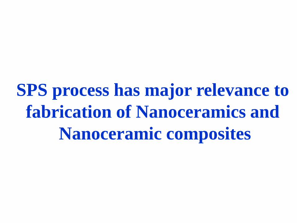
Spark plasma sintering (SPS)
Initial activation of powders by pulsed voltage.
Resistance sintering under pressure.
Heating rate: upto
600K/min.
Sintering temperature
lower by 200-3000C.
Holding time 0-10 min.
Total processing time:
20 min.
Benefits:
Reduced sintering
time.
Good grain to grain
bonding.
Clean grain
boundaries.
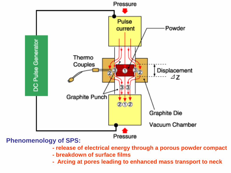
Phenomenology of SPS:- release of electrical energy through a porous powder compact
- breakdown of surface films
- Arcing at pores leading to enhanced mass transport to neck

SPS effect
Simultaneous application of mechanical
pressure and high power pulse source
(upto 6 kA).
Pulsed direct current leading to cleaning
and surface activation of powders.
Generation of electric discharge at the
neck region

In the presence of pressure and electric current, localized
necking occurs faster due to joule heating. Consequently, the
temperature raises very fast (faster than conventional sintering and
Hot pressing) and the densification is completed within few minutes.
Neck formation due to localized heating
Joule’s heating: localized
temperature increment
Groza et al., UC Davis

Experimental: Spark Plasma Sintering
Heating rate : 600 – 650 K/min; Maximum pressure: 50-60 MPaDC Voltage : 5 – 10 V; Pulse frequency: 30-40 kHZVacuum: 60-70 mtorr; Sintering time: 5 minutes

When spark discharge appears in the gap between the particles of a
material, a local high temperature state occurs. This causes
vaporization and the melting of the surfaces of the powder particles
during the SPS process; constricted shapes or “necks” are formed
around the contact area between the particles. These necks
gradually develop and plastic transformation progresses during
sintering, resulting in a sintered compact of over 99% density. Since
only the surface temperature of the particles rises rapidly by self-
heating, particle growth of the starting powder materials is controlled.

Pressure
Molten layer
Vaporization layer
Vaporization layer
Molten layer
Discharge column
(Spark Plasma)
pressure
Thermal diffusion
Field diffusion layerAt neck
Electromigration
(displacement) and plastic
deformation
PressurePressurePowder Particles(A)
Electrons
Vacuum
Ar/air
Powder Particles(B)Pressure
(I) Initial stage of spark discharging
by ON-OFF pulse energization
Anode
Pressure
Spark impact pressure
Vaporized particles
Cathode
(IV) Generation of spark impact pressure, sputtering of
vaporized/molten particles
(V) Enhanced neck growth in the presence of
spark plasma
(II) Generation of spark plasma (III) Vaporization and melting action
on the particles surface
Pressure
Spark plasma
ionization
ion
pressure

The pulsed discharge achieved by the application of an on/off
low voltage (~ 30 V) and high current (> 600 A). The duration of
each pulse varies between 1 and 300 ms, between 2 and 30 ms.
The subsequent step comprises the application of a DC current
at a level dependent on the powder type. The pulsed and direct
current may be applied simultaneously or sequentially.
For SPS Process, electrical discharge per se does not
consolidate powders and, therefore, some additional effects are
needed to increase the final density (pressure application and/or
higher temperature than that created by electrical discharge
Pressure applied at constant/variable level during the process.
SPS process (contd..)
SPS sintering temperatures range from low to over 2000oC,
which are typically ~ 200-500oC lower than conventional sintering
Vaporization, melting and sintering completed in short periods
of ~ 5-20 minutes, including temperature rise and holding times

Formation of small capacitors at the contact between
particles/at gap around the contact.
Electrical discharges are generated across these capacitor
gaps. The interfering surface oxide films are pierced beyond a
certain voltage level, depending on the dielectric strength of
oxide layer. This takes place when the arcing across the particles
leads to achieving the breakdown voltage and electrical
breakdown of dielectric film on the powder particle surface.
Alternatively, the electrical discharges around the contacts
may generate plasma, that is, an ionized gas between the powder
particles.
The above phenomena collectively contribute to the physical
activation of the powder particle surface. The physical activation
combined with faster densification at lower temperatures
reduces grain coarsening and retains a finer microstructure.
Physics of SPS process

Three mechanisms may contribute to field assisted sintering:
activation of powder particles by pulsed current
resistance sintering
pressure application
This activation is unique and provides main difference from
more conventional resistance sintering processes (hot pressing).
The surface activation results in clean grain boundaries. The
grain boundary area shows direct grain-to-grain contact, which
is attributed to the physical activation of powder particle
surfaces during pulsed current application i.e. enhanced grain
boundary diffusion process.
SPS process

Effect of pulsed DC
Formation of capacitor banks at the surface insulatingfilms.
Generation of electrical discharges across thecapacitors (might result in plasma).
Discharges manifested by the presence of arc, aidingin material transport.
Localized heating of powder surfaces.
Breakdown of insulating films due to thermal andelectrical breakdown.
Enhanced diffusion (sintering) kinetics, cleaninterfaces and good grain to grain bonding.

Phenomenology of SPS:- release of electrical energy through a porous powder compact
- breakdown of surface films
- Arcing at pores leading to enhanced mass transport to neck

SPS effect
Simultaneous application of mechanical
pressure and high power pulse source
(upto 6 kA).
Pulsed direct current leading to cleaning
and surface activation of powders.
Generation of electric discharge at the
neck region

Fundamental heat transfer equation to solve:
Solution provides:
1
12
dT q
dr k
When 10 r r
2
1 1 22
2 2
1
2 2
r q qdT q
dr k k r
When 1 2r r r
Simulation of Temperature Profiles in SPS
t
Tq
T
r
Tr
rr
1.
2
21
Devesh Tiwari, B. Basu and K. Biswas; Simulation of Thermal and Electric field
Evolution during Spark Plasma Sintering; Ceramics International (2008)

Simulation of Temperature Profiles in SPS
Surface temperature:
1/ 42
412 2 2 1 22
2
1
2
rT q r q q T
r
,
= emissivity of graphite die
= Stefan-Boltzman Constant

MATLAB Simulation of Temperature Profiles in SPS
Temperature gradient across powder compact strongly sensitive to
both power input and thermal conductivity.
No significant difference in gradient observed for high thermal
conductivity (40 W/m.K or above)
Power input - 0.5x10⁷ W/m3
die wallpowder compact
2
.
1

Power input : 2.0 x 10⁷ W/m3
MATLAB Simulation results (contd ..)
For lower thermal conductivity (20 W/m.K or less), the
temperature gradient increases with power input level.
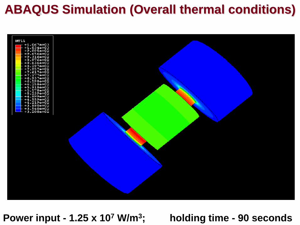
ABAQUS Simulation (Overall thermal conditions)
Power input - 1.25 x 10⁷ W/m3; holding time - 90 seconds
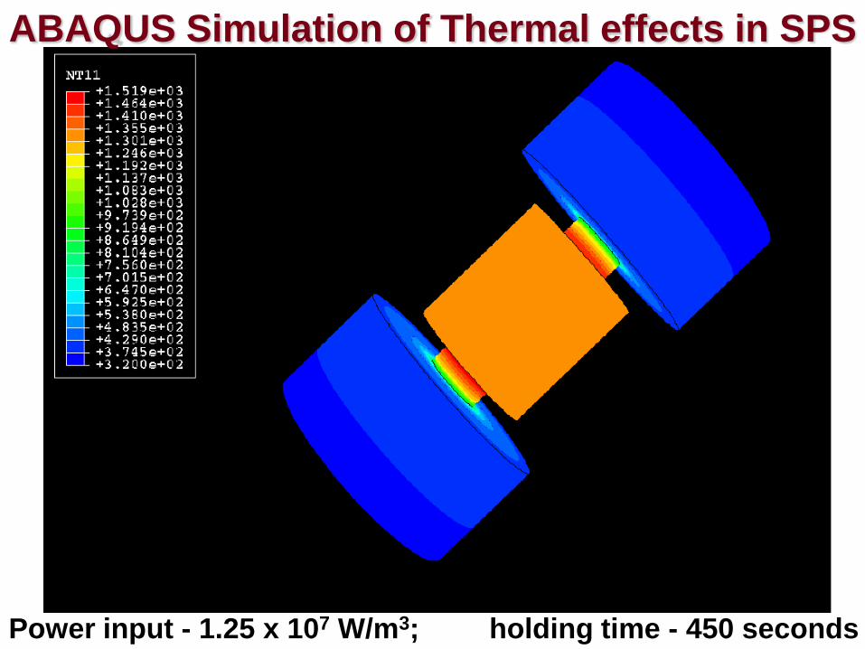
ABAQUS Simulation of Thermal effects in SPS
Power input - 1.25 x 10⁷ W/m3; holding time - 450 seconds

ABAQUS Simulation of thermal effect (closer view)
Power input - 1.25 x 10⁷ W/m3; holding time - 90 seconds

ABAQUS Simulation (closer view of punch/die)
Power input - 1.25 x 10⁷ W/m3; holding time - 450 seconds

Electrical Current Density, ECD
Amount of heat flux,
Electrical Current Density and Heat Flux
12 VVECCJ
12 VVTCCq
C
L
AR
TT
TT
TTCCorTECC0
0
0exp
)()(
ECC - electrical contact conductance (Ω-1m-2),
TCC - thermal contact conductance (W-1m-2K-1)
R0 - static electrical (or thermal) contact resistance
measured at reference temperature T0,
AC - contact area, and are empirical constants.

ABAQUS Simulation: ECD effect
Power input - 1.25 x 10⁷ W/m3; holding time - 90 seconds

ABAQUS Simulation: ECD effect
Power input - 1.25 x 10⁷ W/m3; holding time - 450 seconds

Power input - 1.25 x 10⁷ W/m3; holding time - 90 seconds
ABAQUS Simulation: Heat Flux Distribution effect

ABAQUS Simulation: Heat Flux Distribution effect
Power input - 1.25 x 10⁷ W/m3; holding time - 450 seconds

In the presence of pressure and electric current, localized
necking occurs faster due to joule heating. Consequently, the
temperature raises very fast (faster than conventional sintering and
Hot pressing) and the densification is completed within few minutes.
Neck formation due to localized heating
Joule’s heating: localized
temperature increment
Groza et al., UC Davis

Because of faster heating rate, initial stage of sintering i.e. surface
diffusion avoided
Localized increase in temperature at particle/particle contact leads to
faster mass transport process; D = f (T, ECD) under electric field

Experiments/Modeling for better understanding
An unified model required to explain the mechanisms of
enhanced sintering during SPS process
4
6 192
r
t
KT
Db
rx
3
5 80
r
t
KT
Dl
rx
Modification of above neck growth equations considering
electric field effect and temperature gradient during SPS
Top Related