


Languages
Pages
Legal


Sheet Metal Forming 2.810
D. Cooper
w �Sheet Metal Forming� Ch. 16 Kalpakjian w �Design for Sheetmetal Working�, Ch. 9 Boothroyd, Dewhurst and Knight

Examples-sheet metal formed
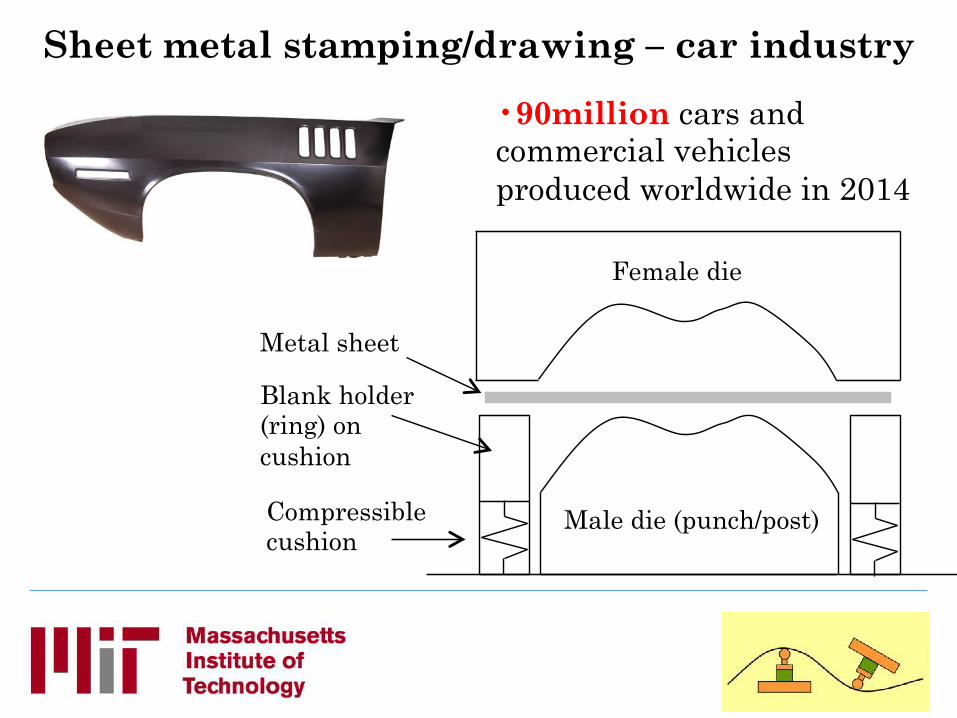
Female die
Male die (punch/post)
Metal sheet
Blank holder (ring) on cushion
Compressible cushion
Sheet metal stamping/drawing – car industry
• 90million cars and commercial vehicles produced worldwide in 2014

Stamping Auto body panels
• 3 to 5 dies each • Prototype dies ~ $50,000 • Production dies ~ $0.75-1 mil.
• Forming dies • Trimming station • Flanging station

By the end of today you should be able to…
…describe different forming processes, when they might be used, and compare their production rates, costs and environmental impacts
…calculate forming forces, predict part defects (tearing, wrinkling, dimensional inaccuracy), and propose solutions
…explain current developments: opportunities and challenges
Objectives

LMP Shop Brake press Finger brake
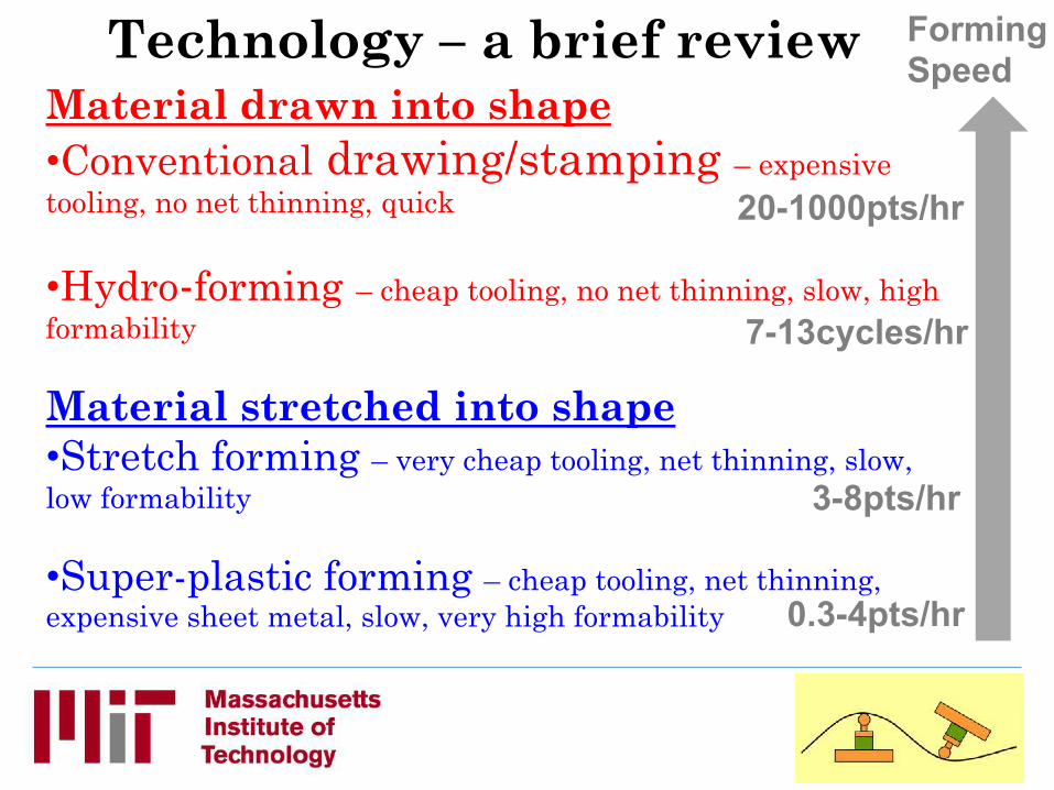
Material drawn into shape • Conventional drawing/stamping – expensive tooling, no net thinning, quick
• Hydro-forming – cheap tooling, no net thinning, slow, high formability
Material stretched into shape • Stretch forming – very cheap tooling, net thinning, slow, low formability
• Super-plastic forming – cheap tooling, net thinning, expensive sheet metal, slow, very high formability
Technology – a brief review Forming Speed
20-1000pts/hr
7-13cycles/hr
3-8pts/hr
0.3-4pts/hr
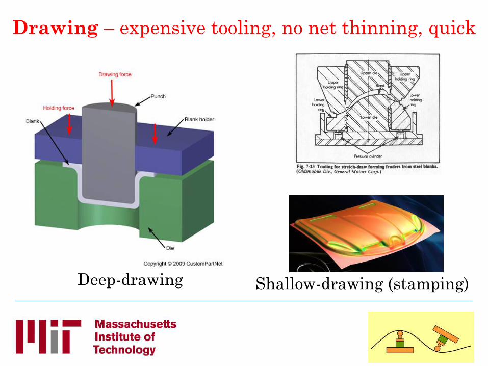
Drawing – expensive tooling, no net thinning, quick
Shallow-drawing (stamping) Deep-drawing

Deep-drawing
Blank holder helps prevent wrinkling and reduces springback Blank holder not necessary if blank diameter / blank thickness is less than 25-40. Smaller values for deeper forming.

http://www.thomasnet.com/articles/custom-manufacturing-fabricating/wrinkling-during-deep-drawing

Tearing
Window for forming
Wrinkling
Blankholder force
Dep
th o
f dra
w
Blank holder force: forming window

Hosford and Duncan (can making): http://www.chymist.com/Aluminum%20can.pdf
Deep Drawing of drinks cans

Hydro-forming – cheap tooling, no net thinning, slow(ish), high formability
Low volume batches

Hydro-forming – cheap tooling, no net thinning, slow(ish), high formability
Low volume batches

Hydro-forming – cheap tooling, no net thinning, slow, high formability
Small flexforming tool made by additive manufacturing
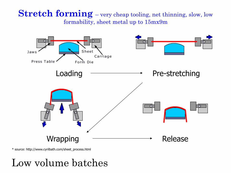
Stretch forming – very cheap tooling, net thinning, slow, low formability, sheet metal up to 15mx9m
Loading Pre-stretching
Wrapping Release * source: http://www.cyrilbath.com/sheet_process.html
Low volume batches

Higher aspect ratio, deeper parts
Stretch forming: Example parts
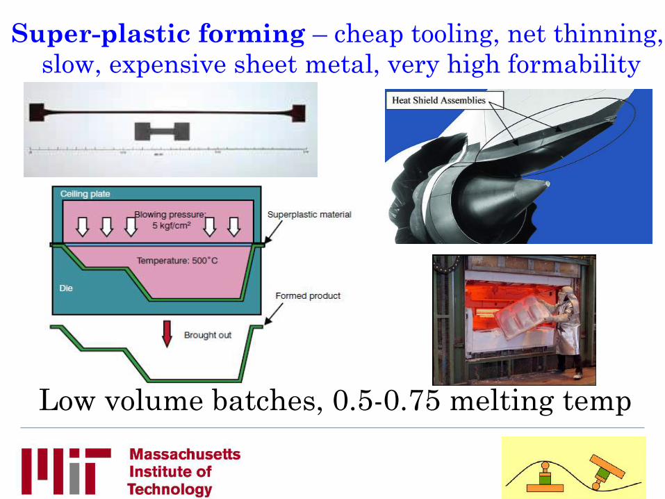
Super-plastic forming – cheap tooling, net thinning, slow, expensive sheet metal, very high formability
Low volume batches, 0.5-0.75 melting temp

Forming forces and part geometry

Tensile test – the Stress-strain diagram
σy=Y
UTS

Nominal strain

True stress & strain
€
εtr = ln(1+εen )σ tr = σ en (1+εen )
True stress can be expressed using a power law (Hollomon
equation):
€
σ tr = Kε trn
σy=Y

Power-Law Expression (Hollomon equation)
€
σ tr = Kε trn
€
log(σ tr ) = n log(ε tr )+ logKCan be re-written:
-3 -2 -1 0
€
log(σ tr )
€
log(ε tr )

Power-Law Expression (Hollomon equation)
€
σ tr = Kε trn
€
log(σ tr ) = n log(ε tr )+ logKCan be re-written:
-3 -2 -1 0
n k
€
log(σ tr )
€
log(ε tr )


Tensile instability - necking

Useful assumptions
Only interested in plastic effects: Perfectly plastic material
At Y, material defoms (�flows�) in compression and fails in tension
Interested in elastic and plastic effects: Elastic-perfectly plastic material
Y or UTS
ε
σ
ε
σ
E
Y or UTS

3D Problems
In 1-D, assuming perfectly plastic, yielding at:
€
σ =Y
€
σ = Kε n
In 3-D, assuming perfectly plastic, yielding at:
€
σ eff = Kεeffn
€
σ eff =Y

3D Yield Criteria Tresca: Yielding occurs at a maximum shear stress
Von Mises: Yielding at maximum distortion strain energy
Effective stress (in principal directions): Effective stress (in principal directions):
Yield criterion: Effective strain:
Yield criterion: Effective strain:
€
σ eff = Y
τmax = k =Y2
€
σ eff = σ i −σ j[ ]max,i≠ j
€
σ eff = Y
Y = 3k€
σ eff =12×
σ 2 −σ 3( )2 + σ 3 −σ1( )2
+ σ1 −σ 2( )2%
& ' '
(
) * *
€
εeff = ε i( )max
€
εeff =23# $ % & ' ( × ε1
2 +ε22 +ε3
2( )

Die
Sheet Punch T
D
Part or slug
Shearing
F = 0.7 T L (UTS)
T = Sheet Thickness L = Total length Sheared UTS = Ultimate Tensile Strength of material
Shear press - LMP Shop

Side Note: For a general state of stress use �effective stress�
Yielding occurs when σeffective = Y
Material taken from Metal Forming, by Hosford and Caddell

Origin of effective strain
σ = Kε n
Material taken from Metal Forming, by Hosford and Caddell

3D Yield Effective stress
Tresca predicts ‘flow’ for lower stresses than
von Mises
€
σ3 = 0€
σ2
€
σ1

Forming Limit Diagrams


Tensile test ε1=-2ε2
ε1=n=necking

Pure Shear ε1=-ε2

Stretch forming: Forming force
F = (YS + UTS)/2 * A F = stretch forming force (lbs) YS = material yield strength (psi) UTS = ultimate tensile strength of the material (psi) A = Cross-sectional area of the workpiece (in2)

Forces needed to bend sheet metal

Bending
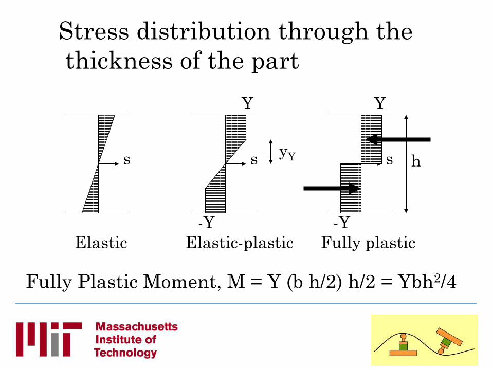
Stress distribution through the thickness of the part
s s yY
Y
-Y
Y
Elastic Elastic-plastic
Fully Plastic Moment, M = Y (b h/2) h/2 = Ybh2/4
s h
-Y Fully plastic

Balance external and internal moments
σ h
-Y Fully plastic
F
F/2 F/2
Ybh2/4 = FL/4 = Mmax
F = bh2Y/L
L
σ
ε
E
εy
σY

Bending Force Requirement
Punch Workpiece T
Die
W
Force
T = Sheet Thickness W = Width of Die Opening L = Total length of bend
(into the page)
UTS = Ultimate Tensile Strength of material
)(2
UTSWLTF =
Note: the notation used in the text (L, W) differs from that used in the previous development (b, L).

LMP Shop Brake press Finger brake

What shape have we created?

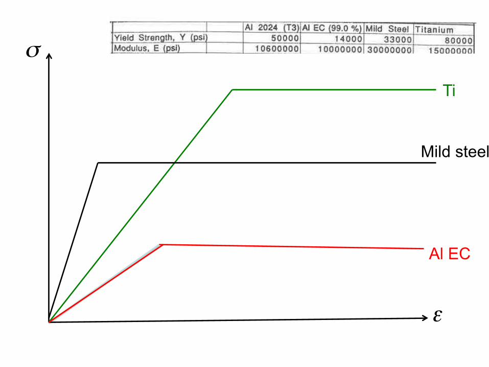
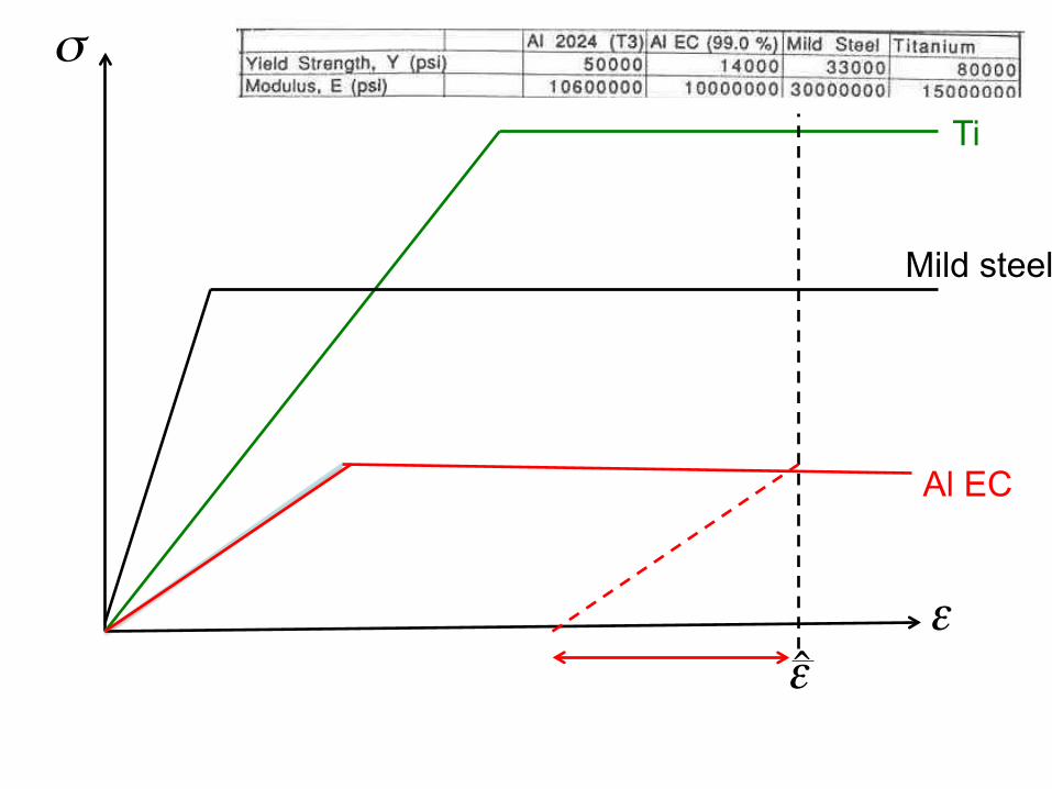
Strength (σy) versus Stiffness (E)
Steel versus aluminum…
Mild steel (33,000psi) & Al. 5052H32 (33,000psi)
Mild steel (30E6psi)
Al. 5052H32 (10.6E6psi)

Steel versus aluminum…
Mild steel (33,000psi) & Al. 5052H32 (33,000psi)
Mild steel (30E6psi) Low spring back
Al. 5052H32 (10.6E6psi) High spring back
Strength (σy) versus Stiffness (E)

Steel versus aluminum…
Mild steel (33,000psi) & Al. 5052H32 (33,000psi)
Al. 2024T3 (50,000psi)
Strength (σy) versus Stiffness (E)
Mild steel (30E6psi) Low spring back
Al. 2024T3 & 5052H32 (10.6E6psi) High spring back

Steel versus aluminum…
Mild steel (33,000psi) & Al. 5052H32 (33,000psi) Low spring back
Al. 2024T3 (50,000psi) High spring back
Strength (σy) versus Stiffness (E)
Mild steel (30E6psi) Low spring back
Al. 2024T3 & 5052H32 (10.6E6psi) High spring back
€
σ
€ €
ε
Al EC
Mild steel
Ti

€
σ
€ €
ε
Al EC
Mild steel
Ti
€
ˆ ε
€
σ
€ €
ε
Al EC
Mild steel
Ti
€
ˆ ε

€
σ
€ €
ε
Al EC
Mild steel
Ti
€
ˆ ε

Springback note R in the figure below is mislabeled, should go to the centerline of the sheet

Elastic Springback Analysis
L
x
y
h
b
1. Assume plane sections remain plane: ey = - y/r (1)
2. Assume elastic-plastic behavior for material
M
r = 1/K M
y
s
e
E
ey
sY σ = E e e <e ψ
σ = σY e >e
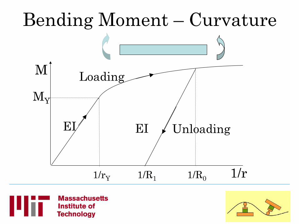
Bending Moment – Curvature
M
1/r
EI
1/rY
MY
Loading
EI Unloading
1/R0 1/R1

M
1/ρ
EI
1/ρY
MY
Loading
EI Unloading
1/R01/R1
3. We want to construct the following Bending Moment �M� vs. curvature �1/ρ� curve
Springback is measured as 1/R0 – 1/R1 (2) Permanent set is 1/R1
!"
#$%
&−=
1
11)1( R
MMY
Y
ρρ

4. Stress distribution through the thickness of the beam
σ σ yY
Y
-Y
σ h
-Y
Y
Elastic Elastic-plastic Fully plastic

5. M = ∫A σ y dA
Elastic region
At the onset of plastic behavior
σ = - y/ρ E = - h/2ρ E = -Y (4) σ
Y
This occurs at
1/ρ = 2Y / hE = 1/ρY (5)
dσ
ydA b
hdy
Substitution into eqn (3) gives us the moment at on-set of yield, MY
MY = - EI/ρY = EI 2Y / hE = 2IY/h (6)
After this point, the M vs 1/r curve starts to �bend over.� Note from M=0 to M=MY the curve is linear.
ρρσ
EIdAyEydAM −=−== ∫ ∫2
(3)

In the elastic – plastic region σ yY
Y
YbyyhYb
ybyYyYb
YbydyyyYbydyybdyM
YY
y
Y
h
y
h
y
y
Y
Y
Y
Y
Y
222
0
32/2
2/
0
32)
4(
32
22
22
+−=
+=
+== ∫ ∫ ∫σ
!!"
#
$$%
&'(
)*+
,−=22
2/311
4 hyYbhM Y
Note at yY=h/2, you get on-set at yield, M = MY And at yY=0, you get fully plastic moment, M = 3/2 MY
(7)

To write this in terms of M vs 1/ρ rather than M vs yY, note that the yield curvature (1/ρ)Y can be written as (see eqn (1))
2/1
hY
Y
ερ
= (8)
Where εY is the strain at yield. Also since the strain at yY is -εY, we can write
Y
Y
yε
ρ=
1(9)
Combining (8) and (9) gives
ρρ1)1(
2/YY
hy
= (10)

Substitution into (7) gives the result we seek:
!!"
#
$$%
&''(
)**+
,−=
2
1)1(
311
23
ρρ Y
YMM (11)
M
1/ρ
EI
1/ρY
MY
Loading
EI Unloading
1/R01/R1
Eqn(11)
Elastic unloading curve !"
#$%
&−=
1
11)1( R
MMY
Y
ρρ(12)
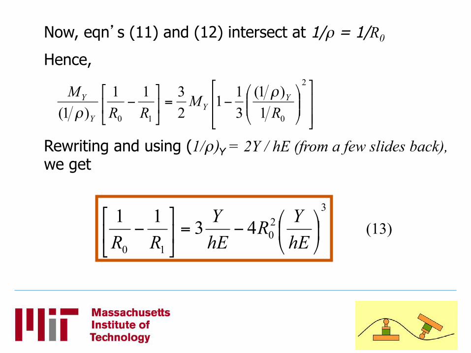
Now, eqn�s (11) and (12) intersect at 1/ρ = 1/R0
Hence,
!!"
#
$$%
&''(
)**+
,−=!
"
#$%
&−
2
010 1)1(
311
2311
)1( RM
RRM Y
YY
Y ρρ
Rewriting and using (1/ρ)Y = 2Y / hE (from a few slides back), we get
320
10
4311!"
#$%
&−=()
*+,
-−
hEYR
hEY
RR(13)

R0=R1
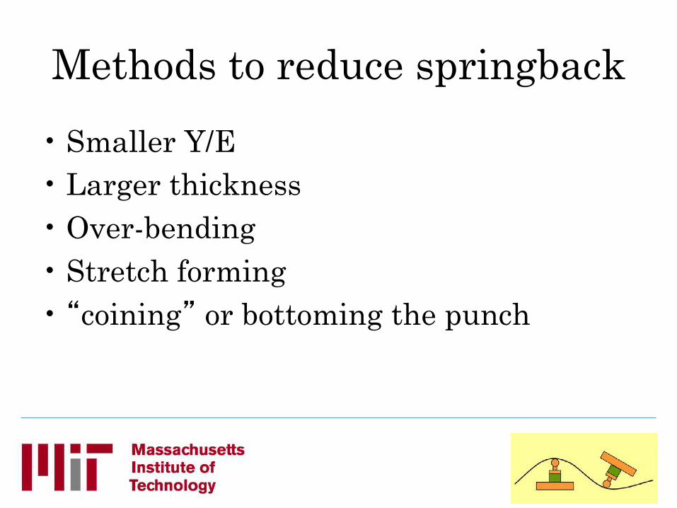
Methods to reduce springback
• Smaller Y/E • Larger thickness • Over-bending • Stretch forming • �coining� or bottoming the punch

Pure Bending
Bending & Stretching
σ h
-Y Fully plastic
σ h
Y Fully plastic
Y
Y
tension
compression
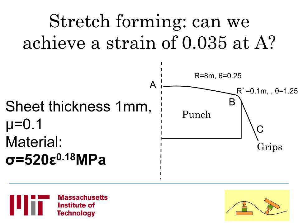
Stretch forming: can we achieve a strain of 0.035 at A?
Sheet thickness 1mm, µ=0.1 Material: σ=520ε0.18MPa
Grips
Punch
R=8m, θ=0.25
R�=0.1m, , θ=1.25 A
B
C
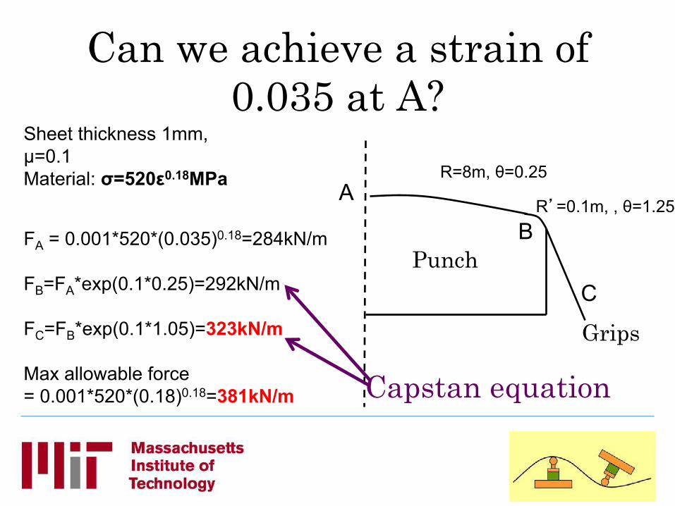
Can we achieve a strain of 0.035 at A?
Sheet thickness 1mm, µ=0.1 Material: σ=520ε0.18MPa
FA = 0.001*520*(0.035)0.18=284kN/m FB=FA*exp(0.1*0.25)=292kN/m FC=FB*exp(0.1*1.05)=323kN/m Max allowable force = 0.001*520*(0.18)0.18=381kN/m
Grips
Punch
R=8m, θ=0.25
R�=0.1m, , θ=1.25 A
B
C
Capstan equation
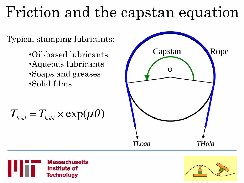
Friction and the capstan equation
€
Tload = Thold × exp(µθ )
• Oil-based lubricants • Aqueous lubricants • Soaps and greases • Solid films
Typical stamping lubricants:

Research opportunities and challenges: reducing cost and environmental
impacts

Energy & cost: Stamping alum car hoods
• Final part = 5.4kgs • Total number of parts made = 400 • Die material: cast and machined zinc alloy
Source: Unpublished work: Cooper, Rossie, Gutowski (2015)
Excludes equipment depreciation and labor during forming
1743%
16%
590%
Energy.(2.3GJ/pt.(Stamping(alum.(car(hoods.(5.4kgO/P.((400pts)(
Sheet (MJ/pt)
Elec (MJ/pt)
Die (MJ/pt)
18# 0#
118#
Cost.&136USD/pt&
Sheet (USD/pt)
Elec (USD/pt)
Die (USD/pt) Sheet metal scrapped in factory = 44%

6 feet
60 Ton Discrete Die Press (LMP - Hardt)

-
SHAPEMEASUREMENT
SHAPECONTROLLER WORKPIECE
desiredshape + shape
error
finishedpartDISCRETE DIE
SURFACE
DISCRETE DIEFORMING PRESS
CONTROLLER
TRACING CMM
Part Error
Die ShapeChange
NewPartShape
The Shape Control Concept

Stretch Forming with Reconfigurable Tool @ Northrop
Grumman

Flexible Forming at Ford
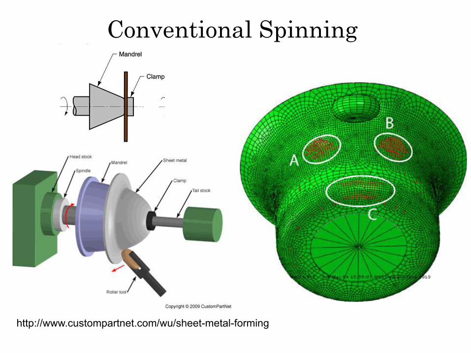
Conventional Spinning
http://www.custompartnet.com/wu/sheet-metal-forming

Music, O., & Allwood, J. M. (2011). Flexible asymmetric spinning. CIRP Annals - Manufacturing Technology, 60(1), 319–322. doi:10.1016/j.cirp.2011.03.136
Flexible Spinning

Polyblank, J. a., Allwood, J. M., & Duncan, S. R. (2014). Closed-loop control of product properties in metal forming: A review and prospectus. Journal of Materials Processing Technology, 214(11), 2333–2348. doi:10.1016/j.jmatprotec.2014.04.014
Greater accuracy required
Too slow?
Thank you
Resourceful Manufacturing & Design Group
http://remade.engin.umich.edu
Top Related