


Languages
Pages
Legal


Semester Project: Bluetooth Remote Control Page 1
STEPHAN Mathieu Friday, June 6, 2008
Semester Project:
Bluetooth Remote Control
Semester Project: Bluetooth Remote Control Page 2
Introduction
In our master cursus at EPFL, we have the possibility to do a semester project on which we
have to work for 12 hours per week. The subject of this project can be either one of the suggested by
the LAP laboratory or one chosen by a student. The subject of the semester project described in this
document has been chosen by me, as it was something I wanted to do for a long time.

Semester Project: Bluetooth Remote Control Page 3
Table of contents
I) Aim of the project
II) Components choice
- Microcontroller
- Bluetooth chip
- Audio codec
- LCD screen
III) Power handling
- Microcontroller
- Bluetooth chip
- Audio codec
- LCD screen
IV) Work done
- Components choice
- Components placement and routing
- Firmware creation
- Plugin creation
- Box creation
V) Communication overview
VI) Work done – Firmware details
- LCD screen interfacing
- Bluetooth module interfacing
- Audio CODEC interfacing
- Graphic library
- HID device
- Protocol used
VII) Improvements
VIII) Evolution
IX) Conclusion
Semester Project: Bluetooth Remote Control
I) Aim of the project
The goal of this project is to create a complete and functional product, starting
Thus, you will see in this report many steps described, starting from the choice of components to the
creation of DLLs for Windows.
We want to create a Bluetooth remote control having several functionalities:
- Display on a small LCD screen the tracks in the multimedia player’s
them using the keys on the
- Display on the LCD the currently played track and its playing status
- Headset functionality: it is possible to plug a standard
remote in order to use the remote control as a headset to make
- External keyboard capability: when the remote control is
appropriate USB cable, the remote will be detected as an external keyboard (using the HID
class). Thus, if the user’s computer doesn’t have a Bluetooth chip, he will still be
control his multimedia player using the special keys
- Provide a platform with free tools: the compiler and the development environment are free,
the compiled program can be sent to the microcontroller by using the USB bootloader. Thus
anyone can develop on the remote without spending money
- Good autonomy: the remote control will be powered using a lithium battery which will be
charged when the remote
Thus, the only part of the whole system on which this project relies is the Windows Bluetooth
system drivers, since we don’t take care of the low level parts of the Bluetooth communication. This
project uses the serial port profile on top of the Bluetooth stack
Semester Project: Bluetooth Remote Control
The goal of this project is to create a complete and functional product, starting
Thus, you will see in this report many steps described, starting from the choice of components to the
We want to create a Bluetooth remote control having several functionalities:
Display on a small LCD screen the tracks in the multimedia player’s playlist;
them using the keys on the remote.
the currently played track and its playing status.
Headset functionality: it is possible to plug a standard microphone and headphones on the
remote in order to use the remote control as a headset to make VoIP calls
External keyboard capability: when the remote control is connected to a computer using
USB cable, the remote will be detected as an external keyboard (using the HID
class). Thus, if the user’s computer doesn’t have a Bluetooth chip, he will still be
control his multimedia player using the special keys on the remote.
rm with free tools: the compiler and the development environment are free,
the compiled program can be sent to the microcontroller by using the USB bootloader. Thus
anyone can develop on the remote without spending money on the development tools.
Good autonomy: the remote control will be powered using a lithium battery which will be
charged when the remote is connected to a computer, using USB power.
Thus, the only part of the whole system on which this project relies is the Windows Bluetooth
em drivers, since we don’t take care of the low level parts of the Bluetooth communication. This
project uses the serial port profile on top of the Bluetooth stack on both sides.
Overview of the device
Page 4
The goal of this project is to create a complete and functional product, starting from scratch.
Thus, you will see in this report many steps described, starting from the choice of components to the
We want to create a Bluetooth remote control having several functionalities:
playlist; navigate through
microphone and headphones on the
calls.
a computer using the
USB cable, the remote will be detected as an external keyboard (using the HID
class). Thus, if the user’s computer doesn’t have a Bluetooth chip, he will still be able to
rm with free tools: the compiler and the development environment are free,
the compiled program can be sent to the microcontroller by using the USB bootloader. Thus,
the development tools.
Good autonomy: the remote control will be powered using a lithium battery which will be
using USB power.
Thus, the only part of the whole system on which this project relies is the Windows Bluetooth
em drivers, since we don’t take care of the low level parts of the Bluetooth communication. This

Semester Project: Bluetooth Remote Control
II) Components choice
Here we will explain in details which components are chosen for this project
a) Microcontroller
As told before, we need a microcontroller having an USB controller and
bootloader. I chose an 8-bit microcontroller from the AVR family: the AT90USB128
running at 8Mhz, has 128kB of flash memory which will be used to store the graphic library for the
LCD screen, 8kB of ram memory, an embedded USB bootloader and it is possible to compile our
program with avr-gcc before sending it to the flash
b) Bluetooth chip
To avoid antenna dimensioning problems and parasites handling, I chose a component
having an embedded antenna. This component is the LMX9838 from National Semiconductors. It is a
Bluetooth to UART converter with an embedded
Access Profiles (GAP), Service Discovery Application Profile (SDAP) and the Serial Port Profile (SPP). It
is also possible to add a headset profile in it since the LMX9838 has a PCM controller which wil
used to route audio data to an audio codec.
c) Audio codec
The LMX9838 supports 4 different audio codecs. I chose one of them: the Winbond W681310.
It is a low cost, low current consumption PCM audio codec.
d) LCD screen
Since our microcontroller doesn’t have an LCD controller, we need an LCD screen that we can
communicate with a serial bus. I found
a 130*130 pixels LCD controlled using an SPI bus. Even if the communi
packet format, our microcontroller will be able to communicate with it using its SPI bus controller.
Semester Project: Bluetooth Remote Control
in details which components are chosen for this project
As told before, we need a microcontroller having an USB controller and a pre
bit microcontroller from the AVR family: the AT90USB128
running at 8Mhz, has 128kB of flash memory which will be used to store the graphic library for the
LCD screen, 8kB of ram memory, an embedded USB bootloader and it is possible to compile our
gcc before sending it to the flash memory.
To avoid antenna dimensioning problems and parasites handling, I chose a component
having an embedded antenna. This component is the LMX9838 from National Semiconductors. It is a
Bluetooth to UART converter with an embedded Bluetooth stack. It handles several profiles: General
Access Profiles (GAP), Service Discovery Application Profile (SDAP) and the Serial Port Profile (SPP). It
is also possible to add a headset profile in it since the LMX9838 has a PCM controller which wil
used to route audio data to an audio codec.
The LMX9838 supports 4 different audio codecs. I chose one of them: the Winbond W681310.
It is a low cost, low current consumption PCM audio codec.
microcontroller doesn’t have an LCD controller, we need an LCD screen that we can
I found the LCD screen used for all low cost Nokia cellular phones: it is
a 130*130 pixels LCD controlled using an SPI bus. Even if the communication is made using a 9bits
packet format, our microcontroller will be able to communicate with it using its SPI bus controller.
Components interfacing
Page 5
in details which components are chosen for this project and why.
a pre-embedded USB
bit microcontroller from the AVR family: the AT90USB1287. It will be
running at 8Mhz, has 128kB of flash memory which will be used to store the graphic library for the
LCD screen, 8kB of ram memory, an embedded USB bootloader and it is possible to compile our
To avoid antenna dimensioning problems and parasites handling, I chose a component
having an embedded antenna. This component is the LMX9838 from National Semiconductors. It is a
It handles several profiles: General
Access Profiles (GAP), Service Discovery Application Profile (SDAP) and the Serial Port Profile (SPP). It
is also possible to add a headset profile in it since the LMX9838 has a PCM controller which will be
The LMX9838 supports 4 different audio codecs. I chose one of them: the Winbond W681310.
microcontroller doesn’t have an LCD controller, we need an LCD screen that we can
the LCD screen used for all low cost Nokia cellular phones: it is
cation is made using a 9bits
packet format, our microcontroller will be able to communicate with it using its SPI bus controller.
Components interfacing

Semester Project: Bluetooth Remote Control Page 6
III) Power handling
Since this remote control will be powered by a Lithium-Ion battery, we have to take care not
to consume a lot of power. Here are described the different power save modes of every component.
a) Microcontroller
The AT90USB1287 has several power-save modes. The one used in this project is the “power-
down” power-save mode. It is the lowest power consumption mode and will be activated when the
remote has not been used for a long time and no USB and Bluetooth communications are active. The
microcontroller will wake up when the user will press the menu key on the remote.
b) Bluetooth chip
In this project the LMX9838 will use an external crystal to consume less power. It has 4
different power modes that will use depending on how the remote is currently used
c) Audio codec
The W681310 has a power-enable pin. Thus, we will only activate the audio codec when an
audio link has been established.
d) LCD screen
The LCD backlight is the part that consumes the more power. It will be enabled for a short
time when the user is pressing any key on the remote control. The LCD screen controller has a power
down mode where the LCD pixels driving circuit is turned off.
Using the power-saving strategy we obtain these power consumptions:
- Power save mode : 17.3 mW
- Backlight off, headset not plugged, no BT link : 94.4 mW
- Backlight off, headset plugged, no BT link : 95.2 mW
- Backlight on, headset not plugged, no BT link : 277 mW
- Backlight off, headset not plugged, data link : 118 mW
- Backlight on, headset not plugged, data link : 307 mW
- Backlight off, headset plugged, data & audio link : 177 mW
- Backlight on, headset plugged, data & audio link : 347 mW
We can see that by using all the power save modes of every component we can reduce the
power consumption by a factor of 5.5 compared to the lowest power consumption use mode. If the
remote is not used and charged for a long time, the battery won’t be fully discharged since the 3.3V
voltage regulator is not working when the voltage is lower than 3.0V. It is the same for the step-up
for the LCD backlight.

Semester Project: Bluetooth Remote Control Page 7
IV) Work done
Here are described the different steps of the development of the Bluetooth Remote Control.
a) Components choice
As described in the chapters above, the first step of our project was to find the correct chips
that will suit our project needs. A careful check must be done on the buses and packet format used
between the different components.
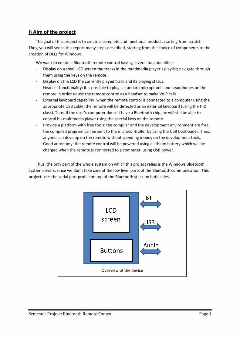
b) Components placement and routing
As I had a precise idea of the Bluetooth general aspect and design, I chose to take care of the
printed circuit board creation.
Three printed circuit board versions have been done in order to obtain our final result.
Bluetooth Remote Schematic
Semester Project: Bluetooth Remote Control Page 8
c) Firmware creation
The main part of this project development is the creation of the remote’s firmware (6500 lines).
Here are the several things done:
- LCD screen interfacing
- Keys interfacing (different modes)
- Bluetooth module interfacing
- Graphic library creation: lines, text, pictures, scrolling…
- Actions needed at first boot: BT profile addition, name & pin change, audio configuration...
- Protocol implementation for the dialog with the media player, using the BT serial port profile
- USB: implementation of a HID device
- Power handling: power save modes, battery voltage sensing
All the function and variables of the program are commented using doxygen. Thus, an HTML
documentation is generated so the programmer can exactly know how the general program works.
Final printed circuit board

Semester Project: Bluetooth Remote Control Page 9
d) Plugin creation
In parallel with the firmware creation, the media player plugin was programmed. The plugin
is actually a Windows DLL created using Microsoft Visual Studio; the media player used is Winamp.
When Winamp is launched, it automatically runs an init function in our DLL located in its plugin
directory. Thus, when this init function is called a thread is created, which will be listening to our
serial port over Bluetooth, decode the requests and send the appropriate answers to the remote.
e) Box creation
As we wanted to create a complete product, a box was designed using Solidworks and
produced using EPFL’s CNC machines.
winampGeneralPurposePlugin plugin =
{
GPPHDR_VER, //
"remote plugin", // Description
init, // Initialization function
config, // Configuration function
quit, // Deinitialization function
0,
0
};
Object returned to Winamp so it knows our program is a plugin
3D box model

Semester Project: Bluetooth Remote Control
V) Communication overview
Once the media player is launched, a Bluetooth communication is established between the
remote and the user computer. When the remote detects that the communication has been
established, it automatically sends a “get_init” message to our plugin in order to
to display on its LCD screen. It will then periodically send “get_update” packets to know if any
changes occurred (title / playlist change, currently played status update…).
The remote only stores 16 titles in his memory. Since w
screen, 8 others are cached so they can be directly displayed when the user browse through the titles.
When the remote sees that its buffer begins to be empty, it then ask
A home-made protocol has been implemented using the serial port. It takes care of packet
fragmenting that can occur, has a command identifier field and a variable packet size.
Communication overview between the remote and the winamp plugin
Semester Project: Bluetooth Remote Control
V) Communication overview
Once the media player is launched, a Bluetooth communication is established between the
remote and the user computer. When the remote detects that the communication has been
established, it automatically sends a “get_init” message to our plugin in order to
to display on its LCD screen. It will then periodically send “get_update” packets to know if any
changes occurred (title / playlist change, currently played status update…).
The remote only stores 16 titles in his memory. Since we can only display 8 titles on the
screen, 8 others are cached so they can be directly displayed when the user browse through the titles.
When the remote sees that its buffer begins to be empty, it then asks the plugin for the missing titles.
protocol has been implemented using the serial port. It takes care of packet
fragmenting that can occur, has a command identifier field and a variable packet size.
Communication overview between the remote and the winamp plugin
Page 10
Once the media player is launched, a Bluetooth communication is established between the
remote and the user computer. When the remote detects that the communication has been
have the list of titles
to display on its LCD screen. It will then periodically send “get_update” packets to know if any
e can only display 8 titles on the
screen, 8 others are cached so they can be directly displayed when the user browse through the titles.
the plugin for the missing titles.
protocol has been implemented using the serial port. It takes care of packet
fragmenting that can occur, has a command identifier field and a variable packet size.
Communication overview between the remote and the winamp plugin
Semester Project: Bluetooth Remote Control Page 11
VI) Work done – Firmware details
Here we will describe in details the work mentioned above: packets, signals…
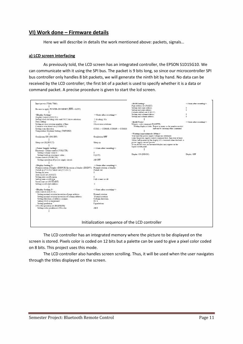
a) LCD screen interfacing
As previously told, the LCD screen has an integrated controller, the EPSON S1D15G10. We
can communicate with it using the SPI bus. The packet is 9 bits long, so since our microcontroller SPI
bus controller only handles 8 bit packets, we will generate the ninth bit by hand. No data can be
received by the LCD controller; the first bit of a packet is used to specify whether it is a data or
command packet. A precise procedure is given to start the lcd screen.
The LCD controller has an integrated memory where the picture to be displayed on the
screen is stored. Pixels color is coded on 12 bits but a palette can be used to give a pixel color coded
on 8 bits. This project uses this mode.
The LCD controller also handles screen scrolling. Thus, it will be used when the user navigates
through the titles displayed on the screen.
Initialization sequence of the LCD controller

Semester Project: Bluetooth Remote Control Page 12
b) Bluetooth module interfacing
To communicate with the LMX9838, we use the UART controller on our microcontroller.
The LMX9838 has a special packet format we have to respect in order to communicate with it.
Each command sent to the Bluetooth module is confirmed by the appropriate message. As our
controller can’t handle the /RTS and /CTS signals, we use the UART in 2 wire mode, so we have to be
sure that our device is fast enough to not miss any data.
Scrolling modes on the EPSON LCD controller
Packet format for the LMX9838
Semester Project: Bluetooth Remote Control Page 13
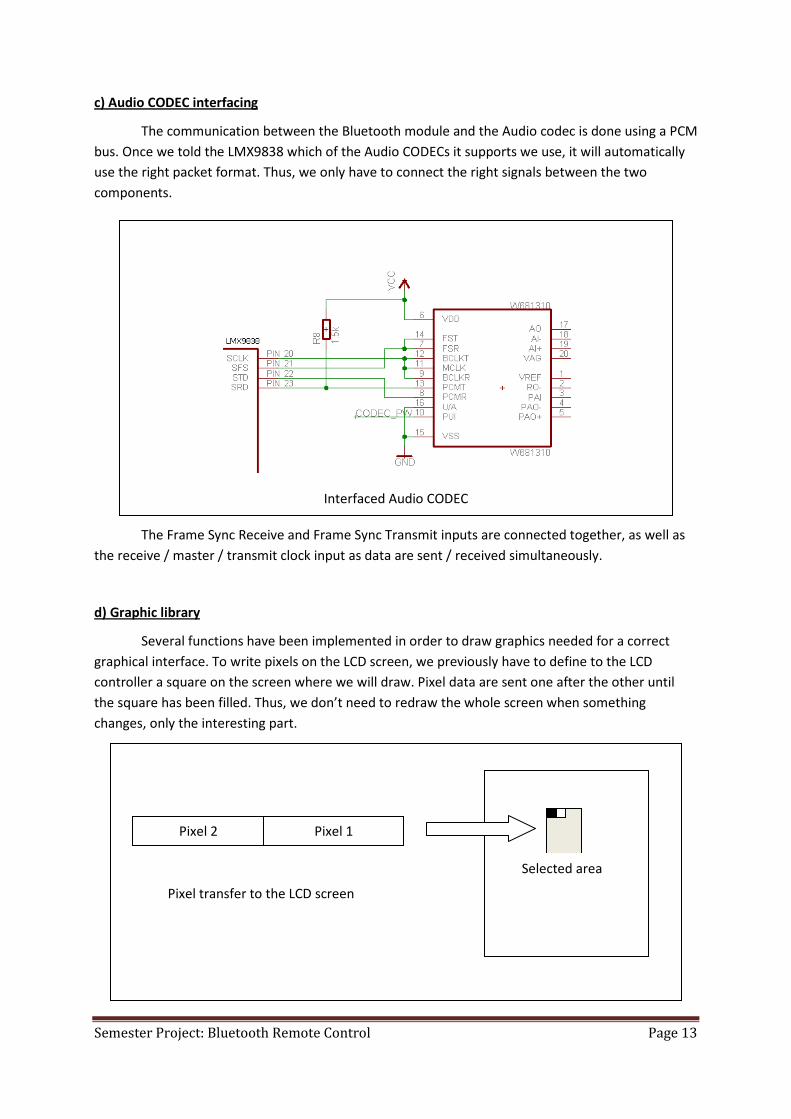
c) Audio CODEC interfacing
The communication between the Bluetooth module and the Audio codec is done using a PCM
bus. Once we told the LMX9838 which of the Audio CODECs it supports we use, it will automatically
use the right packet format. Thus, we only have to connect the right signals between the two
components.
The Frame Sync Receive and Frame Sync Transmit inputs are connected together, as well as
the receive / master / transmit clock input as data are sent / received simultaneously.
d) Graphic library
Several functions have been implemented in order to draw graphics needed for a correct
graphical interface. To write pixels on the LCD screen, we previously have to define to the LCD
controller a square on the screen where we will draw. Pixel data are sent one after the other until
the square has been filled. Thus, we don’t need to redraw the whole screen when something
changes, only the interesting part.
Interfaced Audio CODEC
Pixel transfer to the LCD screen
Pixel 1 Pixel 2
Selected area
Semester Project: Bluetooth Remote Control Page 14
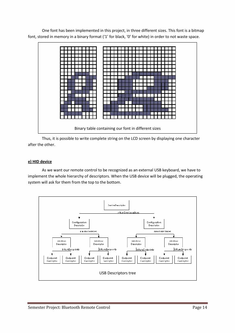
One font has been implemented in this project, in three different sizes. This font is a bitmap
font, stored in memory in a binary format (‘1’ for black, ‘0’ for white) in order to not waste space.
Thus, it is possible to write complete string on the LCD screen by displaying one character
after the other.
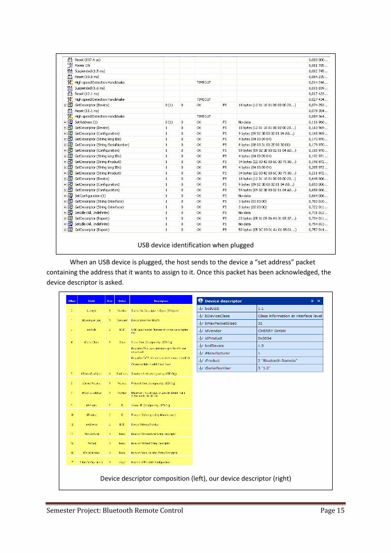
e) HID device
As we want our remote control to be recognized as an external USB keyboard, we have to
implement the whole hierarchy of descriptors. When the USB device will be plugged, the operating
system will ask for them from the top to the bottom.
Binary table containing our font in different sizes
USB Descriptors tree
Semester Project: Bluetooth Remote Control Page 15
When an USB device is plugged, the host sends to the device a “set address” packet
containing the address that it wants to assign to it. Once this packet has been acknowledged, the
device descriptor is asked.
USB device identification when plugged
Device descriptor composition (left), our device descriptor (right)

Semester Project: Bluetooth Remote Control Page 16
For reasons that will see later, we took the Vendor and Product ID from a Cherry multimedia
keyboard. Once the device descriptor has been sent, the other descriptors are asked.
In our configuration descriptor, we define the power needed for our device, several
attributes and the number of interfaces. Our remote control will be detected as a device which has 2
interfaces. One interface will be used for the normal keys (a to z, left/right/up/down arrow) and
another for the multimedia keys (play/pause, next / prev track, increase/decrease volume).
For an HID device, to every interface descriptor is associated an endpoint and an HID
descriptor, so the host knows how to communicate with the device.
Configuration descriptor composition (left), our configuration descriptor (right)
Interface descriptor composition (left), our 2 interface descriptors (right)

Semester Project: Bluetooth Remote Control Page 17
Several transfer types exist for each endpoint. The transfer type used here is Interrupt since
we will periodically check if the user pressed any key. Once the host knows how to communicate
with the device, it will ask each interface for its HID report descriptor describing which keys are on
the keyboard.
Above is the report descriptor used for the keyboard part of our USB device. We can see that
6*8 = 48 bits will be returned indicating which keys are pressed. A key pressed is stored in one of the
6 8bits slots sent every 10ms to the host.
Endpoint descriptor composition (left), our 2 endpoints descriptors (right)
HID report descriptor for the keyboard interface
Semester Project: Bluetooth Remote Control Page 18
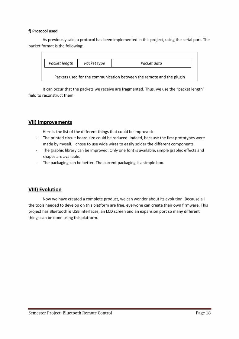
f) Protocol used
As previously said, a protocol has been implemented in this project, using the serial port. The
packet format is the following:
It can occur that the packets we receive are fragmented. Thus, we use the “packet length”
field to reconstruct them.
VII) Improvements
Here is the list of the different things that could be improved:
- The printed circuit board size could be reduced. Indeed, because the first prototypes were
made by myself, I chose to use wide wires to easily solder the different components.
- The graphic library can be improved. Only one font is available, simple graphic effects and
shapes are available.
- The packaging can be better. The current packaging is a simple box.
VIII) Evolution
Now we have created a complete product, we can wonder about its evolution. Because all
the tools needed to develop on this platform are free, everyone can create their own firmware. This
project has Bluetooth & USB interfaces, an LCD screen and an expansion port so many different
things can be done using this platform.
Packets used for the communication between the remote and the plugin
Packet length Packet type Packet data

Semester Project: Bluetooth Remote Control Page 19
IX) Conclusion
In a short amount of time, I managed to create a complete and functional product using all
the means given at my disposal at EPFL. This project was very interesting for me as it needed many
different skills in many different domains.
Final version of the remote
Semester Project: Bluetooth Remote Control Page 20
Annexes
Top Related