


Languages
Pages
Legal


Section ARoof Truss

Office: (715)239-6465 or 723-8817Toll Free: (800)826-6975
Fax: (715)239-6731, Toll Free: (800)826-6974E-mail: [email protected]
Storage Piggy Back
Attic
Gambrel Attic Gambrel
Floor
Parallel ChordSpecial
Tray Vault
Dual Slope
Cathedral
Studio
Mono
Scissor
CommonBobtail
Truss TypesWisconsin Truss, Inc. can build a variety of truss types, pictured below are some common examples.
Section A, Page 1

Peak
Span
Top Chord
Pitch 12
Bottom Chord
Web
Heel
Splice
Web
Joint
Overhang OverhangTop Chord:An inclined or horizontal member that establishes the top of a truss, forming the roof line(s).
Bottom Chord: An inclined or horizontal member that establishes the bottom of a truss, forming the ceiling line(s). An example of an inclined bottom chord member is the bottom chord of a scissors truss.
Web:Members that join the top and bottom chords to form the triangular patterns typical of trusses. These members transfer loads and forces in the truss.
Peak:Point on the truss where the top chords meet, forming a ridge line.
Joint:The location on a truss where the web members intersect the top and/or bottom chord.
Heel:The point on the truss where the top and bottom chord intersect.
Splice:Location at which two chord members are joined together to form a single member. It may occur at a joint or between joint points.
Overhang:The extension of the top chord of a truss beyond the outside of the bearing support.
Pitch/ Slope:Inches of vertical rise for each twelve inches of horizontal run.
Span: Term generally used to communicate out-to-out span or overall bottom chord length.
Office: (715)239-6465 or 723-8817Toll Free: (800)826-6975
Fax: (715)239-6731, Toll Free: (800)826-6974E-mail: [email protected]
Truss TerminologyThe terms below are typically used to describe the various parts of a truss. The profile (shape), heel, and web pattern will vary
with the specific design conditions.
Section A, Page 2

24" 219.2" 1.616" 1.33
If Spacing is Divide by:
When estimating the truss quantity for a building, take the building length divided by the truss spacing factor (shown below) and then add 1 which gives you the total number of trusses required.
Total Length
Total Width(Span)
Office: (715)239-6465 or 723-8817Toll Free: (800)826-6975
Fax: (715)239-6731, Toll Free: (800)826-6974E-mail: [email protected]
Estimating Trusses
Truss Spacing Factor
Example:
If the building is 40' in length and 26' in width and the truss spacing was 24" o.c., then you would take 40' divided by 2 equals 20 . Always remember to add 1 (20 + 1 = 21). For the building as described you would need order 19, 26' common trusses and 2, 26' end frames.
To estimate truss quantities and type for basic rectangular building such as a garage, follow the example below. For complex buildings forward the plans to a truss designer.
Section A, Page 3

Standard End
Ladder System
Section Detail
Common Truss
Lowered End
Ladder System
Section Detail
Common Truss
Common Truss
The standard end uses that same profile (outside shape) as the common truss it is used with. If a rake, or gable overhang is to be added, a ladder frame is usually attached to the top chord of the end. When using this method the overhang usually does not exceed 12".
Office: (715)239-6465 or 723-8817Toll Free: (800)826-6975
Fax: (715)239-6731, Toll Free: (800)826-6974E-mail: [email protected]
Common Truss
Standard End
Ladder Framing System
Lowered End
Ladder Framing System
The lowered end is dropped or lowered from the profile of the common. This allows ladder framing to extend over the end framing and attach to the first common truss. This method is most often used when a rake, or gable overhang greater than 12" is desired. The amount the truss is dropped can be specified by the building designer.
End FramesStudded ends or end frames are used on the end of a building to provide nailing for exterior sheathing. An end frame is a non-
structural framing member and must be fully supported by a bearing wall. There are two types of studded ends, which are described below.Standard End
Lowered End
Lowered End
Section A, Page 4

Office: (715)239-6465 or 723-8817Toll Free: (800)826-6975
Fax: (715)239-6731, Toll Free: (800)826-6974E-mail: [email protected]
Valley SetsValley sets are used to form the ridge line and framing between a main and secondary roof structure.
Valley members may also be used for decorative gables, porches, etc. Flat top valley members are also supplied where required for hip roof applications.
Valley Members
Valley Members
Secondary Roof
Main Roof
Valley Point
Please note:
Each valley member decreases in size by 4' when used on equal sloped roofs. Example, a 20' valley set (used with 20' common truss) would consist of the following valley members16', 12', 8', and 4'.
Please inform designer if the valley set will connect roofs with differing pitches/slopes.
Section A, Page 5

Width (Span)
Length
XX2 X2
X2 X2X
Office: (715)239-6465 or 723-8817Toll Free: (800)826-6975
Fax: (715)239-6731, Toll Free: (800)826-6974E-mail: [email protected]
Hipsets
If a building were 30' wide and 40' long, each hip would peak at 15' from the end of the building. To estimate the flat ridge length and the number of common trusses required, subtract the hip ends from the building length, which equals 10'. This building would require 2-30' hipsets and 6 common trusses.
A hipset consists of: step-down hip trusses, the same span as the common trusses, gradually decreasing in height to form the sloping hip line between the common truss and the hip girder.The hip girder location is determined by the length of the end jacks, generally 8'. The remaining components of the hipset are end jacks, a corner set including a corner girder and corner jacks. The quantities of each component will vary with the span of the hipset. On equal pitch/slope hip roofs, the hip will peak at a horizontal distance that is equal to 1/2 of the span.
A hip roof is a roof which slopes from three sides. A hipset is used to achieve this roof design.
Example:
-
Section A, Page 6

Span W1 H1 Pattern Span W1 H1 Pattern20' 8-0-0 2-9-4 A 20' 9-0-0 3-7-2 A22' 10-0-0 3-0-11 A 22' 11-0-0 3-11-9 A24' 11-0-0 3-4-11 A 24' 12-0-0 4-4-9 A26' 12-0-0 3-8-11 A 26' 13-0-0 4-9-9 A28' 13-0-0 4-0-11 A 28' 13-0-0 5-2-8 A30' 12-6-0 4-4-10 A 30' 13-0-0 5-7-7 A32' 12-0-0 4-8-8 A 32' 13-0-0 5-3-0 B34' 12-0-0 5-1-2 A 34' 13-0-0 5-9-0 B
Span W1 H1 Pattern Span W1 H1 Pattern20' 10-0-0 4-4-7 A 20' 10-0-0 5-3-0 B22' 12-0-0 4-10-8 A 22' 12-0-0 5-6-0 B24' 13-0-0 5-4-8 A 24' 12-6-0 6-6-0 B26' 13-0-0 5-3-0 B 26' 13-0-0 7-0-0 B28' 13-0-0 5-6-0 B 28' 13-0-0 7-6-0 B30' 13-0-0 6-0-0 B 30' 13-0-0 8-1-2 B32' 13-0-0 6-6-0 B 32' 13-0-0 8-1-2 B34' 13-0-0 7-0-0 B 34' 13-0-0 8-1-2 B
4/12 5/12
8/126/12
B
A
30 pounds per sq. ft. (storage load)
W1
H1
Storage Room Openings
Office: (715)239-6465 or 723-8817Toll Free: (800)826-6975
Fax: (715)239-6731, Toll Free: (800)826-6974E-mail: [email protected]
The charts below show the inside dimension of our standard storage trusses.
Note: Web patterns may vary with pitch/slope and span.Dimensions are approximate and are measured in feet, inches and 16th's.
Section A, Page 7

Span W1 H112' 7-0-0 4-10-014' 9-0-0 4-10-016' 10-0-0 6-0-018' 11-0-0 7-0-020' 12-0-0 8-1-222' 13-0-0 8-1-224'' 14-0-0 8-1-226'' 14-0-0 8-1-228' 14-0-0 8-1-230' 16-0-0 8-1-232' 17-0-0 8-1-234' 18-0-0 8-1-236' 18-0-0 8-1-2
H1
W1
40 pounds per sq. ft. (room load)
Gambrel Room Openings
Office: (715)239-6465 or 723-8817Toll Free: (800)826-6975
Fax: (715)239-6731, Toll Free: (800)826-6974E-mail: [email protected]
The chart below shows the inside room dimensions of our standard gambrel attic trusses. Remember flooring, ceiling and wall treatments will decrease these dimensions.
Dimensions are approximate and are measured in feet, inches and 16th's.
Section A, Page 8

Span W1 H1 H2 Span W1 H1 H220' 10-0-0 5-6-0 3-2-6 20' 10-0-0 6-0-0 3-7-222' 11-0-0 6-0-0 3-4-5 22' 11-6-0 6-6-0 3-7-324' 14-0-0 6-3-0 2-10-9 24' 14-0-0 7-0-0 3-3-326' 14-0-0 6-6-0 3-6-9 26' 14-0-0 7-6-0 4-0-328' 14-0-0 6-11-0 4-2-9 28' 14-0-0 7-9-0 4-9-330' 14-0-0 7-3-0 4-10-9 30' 14-6-0 8-0-0 5-3-1532' 14-6-0 7-6-0 5-4-0 32' 14-6-0 8-1-2 6-0-1534' 15-0-0 7-11-0 5-8-9 34' 16-0-0 8-1-2 6-1-3
Span W1 H1 H2 Span W1 H1 H220' 11-0-0 6-6-0 3-6-13 20' 11-0-0 7-6-0 4-3-422' 11-6-0 7-0-0 4-0-1 22' 11-0-0 8-1-2 4-9-1224' 14-0-0 8-1-2 7-7-13 24' 14-6-0 8-1-2 4-2-026' 14-5-0 8-1-2 4-3-12 26' 14-6-0 8-1-2 5-2-028' 14-6-0 8-1-2 5-1-5 28' 14-6-0 8-1-2 6-2-030' 14-6-0 8-1-2 5-11-5 30' 14-6-0 8-1-2 7-2-032' 14-6-0 8-1-2 6-9-5 32' 16-0-0 8-1-2 7-3-034' 16-0-0 8-1-2 6-9-13 34' 16-0-0 8-1-2 8-1-2
9/12 Pitch8/12 Pitch
10/12 Pitch 12/12 Pitch
W1H2
H1
40 pound per sq. ft. (room load)
Attic Room Openings
Office: (715)239-6465 or 723-8817Toll Free: (800)826-6975
Fax: (715)239-6731, Toll Free: (800)826-6974E-mail: [email protected]
The charts below show the inside room dimensions of our standard attic trusses, remember flooring, ceiling and wall treatments will decrease these dimensions.
= Piggy Back (top included)Dimensions are approximate and are measured in feet, inches and 16th's.
Section A, Page 9

Cantilever
Span
Office: (715)239-6465 or 723-8817Toll Free: (800)826-6975
Fax: (715)239-6731, Toll Free: (800)826-6974E-mail: [email protected]
Special Conditions
Energy HeelThe energy heel is used when building an energy efficient building. The heel height is designed higher so that more insulation may be placed over the bearing wall. This helps prevent the hot air from escaping out, where the exterior wall and ceiling meet.
CantileverThe part of the truss that extends beyond it's support, exclusive of the overhang. When ordering a truss with a cantilever, please give the total bottom chord length as the span.
Section A, Page 10

Section BFloor Truss

Depth D Depth 4" 6" 8" 10" 12"12" 7" 12" 26" 13" -- -- --14" 9" 14" 32" 21" 11" -- --16" 11" 16" 36" 27" 18" 9" --18" 12" 18" 39" 31" 23" 15" 8"20" 14" 20" 41" 34" 27" 20" 13"22" 16" 22" 42" 36" 30" 24" 18"24" 18" 24" 44" 38" 32" 27" 21"
Strongbacks run between trusses to help transfer loads, minimize vibrations and stiffen the floor system.
HW
DDepth
Standard Panel 60"
Floor Information
Office: (715)239-6465 or 723-8817Toll Free: (800)826-6975
Fax: (715)239-6731, Toll Free: (800)826-6974E-mail: [email protected]
Duct Work Chart
Wid
th (W
) =
Strongbacks
Strongback spacing should not exceed 10' intervals across span of the truss. Strongbacks are always required and should be lapped a minimum of one truss spacing for continuity. They should extend to and be attached to bearing walls at their ends.
Use the duct work chart below to match the truss depth with the required duct work size. These dimensions apply to floor trusses with standard panels and may not apply to every truss panel.
Rectangular (If Height (H) is:)
These dimensions are approximate.
Round
Central Chase Opening
2'-0" Max
3-16d Nails
2x6 Strongbacks
2-16d Nails @ Top & Bottom of 2x4 Vertical Block
2x6 (min) Strongback
Section B, Page 1

Depth 12" 16" 19.2" 24" Depth 12" 16" 19.2" 24"12" -- 18' 17' 15' 12" 21' 20' 19' 18'14" -- 20' 19' 17' 14" 23' 22' 21' 20'16" -- 22' 21' 19' 16" 26' 25' 24' 22'18" -- 24' 23' 20' 18" 30' 28' 25' 23'20" -- 26' 25' 22' 20" 32' 30' 28' 25'
22" 34' 32' 30' 28'24" 36' 34' 32' 30'
Spacing
3x2 Floor Trusses
40-10-0-5 loading, L/480 max live load deflection
4x2 Floor Trusses
Spacing
Floor Truss Span Charts
Office: (715)239-6465 or 723-8817Toll Free: (800)826-6975
Fax: (715)239-6731, Toll Free: (800)826-6974E-mail: [email protected]
Top Chord BearingBottom Chord Bearing (Standard)
Cantilever
Shown below are the three most common types of floor end conditions.
Use the span charts below to determine floor truss depth and spacing required. Maximum spans shown are from outside to outside of bearings.
Section B, Page 2

Spacing Span12" o.c. 16'-7"16" o.c. 15'-2"
19.2" o.c. 14'-4"24" o.c. 13'-4"
Spacing Span12" o.c. 19'-11"16" o.c. 18'-2"
19.2" o.c. 17'-2"24" o.c. 15'-5"
Spacing Span12" o.c. 24'-4"16" o.c. 22'-1"
19.2" o.c. 20'-2"24" o.c. 18'-0"
11 7/8"
9 1/2"
14"
I-Joist Span Charts
Office: (715)239-6465 or 723-8817Toll Free: (800)826-6975
Fax: (715)239-6731, Toll Free: (800)826-6974E-mail: [email protected]
I-20
I-40
40 PSF live load, 10 PSF dead load, L/480 live load deflection
Maximum spans shown above are clear distances between supports, and are based on composite action glued-nailed sheathing of 23/32" nominal APA rated OSB or plywood.
Section B, Page 3

I-Joist Details
Office: (715)239-6465 or 723-8817Toll Free: (800)826-6975
Fax: (715)239-6731, Toll Free: (800)826-6974E-mail: [email protected]
APA Rim Board vertical load transfer = 2750 plf maximum
one 8d nail at top and bottom flange
Attach APA Rim Boardto top plate using 8d box toenails @ 6" o.c.
One 8d facenail at eachside at bearing
To avoid splitting flange, start nails at least 1-1/2" from end of I-joist. Nails may be driven at an angle to avoid splitting of bearing plate.
PRI or APA Rim Boardblocking panel
squash blockVertical load transfer per pair of squash blocks as shown:Pair of Squash Blocks (lb)2x4 1-1/8" Rim Board1" Rim Board
400030002700
1/16" for lumber squash blocks
LVL beam
Top- or face- mounted hanger installed per manufacturers recommendations
Notes: Unless hanger sides laterally support the top flange, web stiffeners shall be used.
Solid block all posts from above to bearing below. Install squash blocks per 1d. Match bearing area of blocks below to post above.
Top- or face mounted hanger
Double I-joist headerNote: unless hanger sides laterally support the top flange, bearing stiffeners shall be used.
Backer block (use if hanger load exceeds 250 lbs.) before installing a backer block to a double I-joist, drive 3 additional 10d nails through the webs and filler block where the backer block will fit. Clinch. Install backer tight to top flange. Use twelve 10d nails, clinched when possible. Maximum capacity for hanger for this detail = 1280 lb.
Backer block required both sides for face-mounted hangers)
Filler block
Section B, Page 4
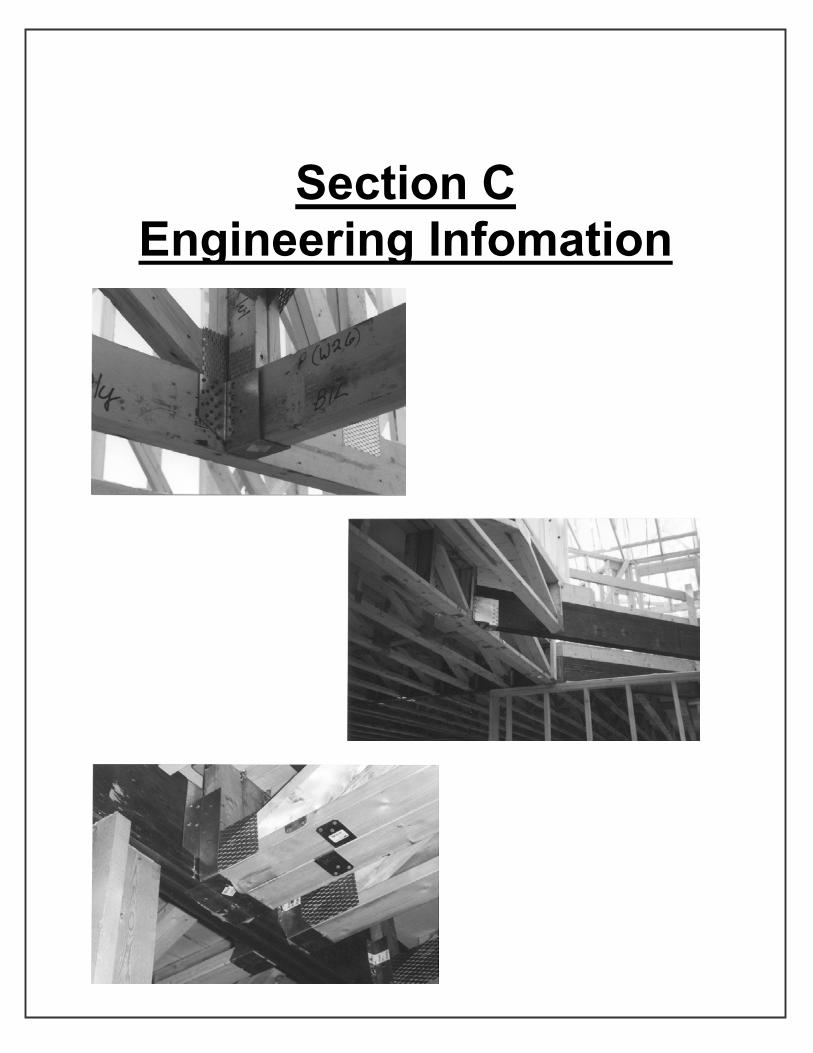
Section CEngineering Infomation

How
to R
ead
Engi
neer
ing
Dra
win
gs
Late
ral
Section C, Page 2

Office: (715)239-6465 or 723-8817Toll Free: (800)826-6975
Fax: (715)239-6731, Toll Free: (800)826-6974E-mail: [email protected]
Engineering Terminology
Bearing:A structural support, usually a beam or wall that is designed by the building designer to carry the truss reaction loads to the foundation.
Cantilever: The part of the truss that extends beyond its support, exclusive of overhang.
Deflection:The amount a member sags or displaces under influence of forces.
Design Loads:The dead and live loads which a truss is designed to support.
Live Load:Any loading which is not of permanent nature, such as snow, wind and temporary construction loads.
Dead Load:Any permanent load such as the weight of the truss itself, purlins, sheathing, roofing and ceiling materials.
Lateral Bracing:A member placed and connected at right angles to a chord or web member of a truss.
Plate:A connector plate manufactured from structural quality steel of various sizes.
Reaction:The total load transferred from the truss to the bearing.
Total Rise:Vertical distance from the bottom of the bottom chord to truss peak or highest point.
Span: The horizontal distance between the outside edges of the exterior walls.
Truss Spacing:The on-center distance between trusses.
The terms below are typically used in describing the proper use and engineering of trusses.
Section C, Page1

3D V
iew
of T
russ
Lay
out
Section C, Page 3

Exam
ple
of T
russ
Lay
out
Section C, Page 4

Section DForms

Store Location:
Associate's Name:
Customer Name:
Date:
____________________________________________________________________________________________________
____________________________________________________________________________________________________
____________________________________________________________________________________________________
____________________________________________________________________________________________________
Bearing Wall Size: 2X4, 2X6, ____" X1: Length of Flat=____'-____" Bottom Chord Pitch:____/12
Special Conditions or Comments
Span: ___'-___"
Pitch: _______12
Overhang: ___'-___"
Height: ___'-___"(If pitch is unknown)
Please check one of the following.
Overhang: ___'-___"
Residential Post Frame16", 24" or ___" 4', 8', 10', 10' or ___'
Residential Post Frame SpecialLive Load Top ChordDead Load Top ChordLive Load Bottom ChordDead Load Bottom Chord
30 407 70 010 10
24 2444
0 01
________________________________________
Circle Loading and Spacing of Trusses(If not listed in charts, please fill in the required information in the spaces provided)
Quantity: Commons: _______ Ends:_______ End Type: Std Dropped
5
ScissorX1
Studio
Office: (715) 239-6465 or 723-8817Toll Free: (800) 826-6975
Fax: (715) 239-6731, Toll Free: (800) 826-6974E-mail: [email protected]
`` (Please check the truss type below, if other than common.)
X1Cathedral Parallel Chord
Mono
____'-____"
Storage Gambrel AtticAttic

____________________________________________________________________________________________________
____________________________________________________________________________________________________
____________________________________________________________________________________________________
____________________________________________________________________________________________________
Special Conditions or Comments
Store Location:
Associate's Name:
Customer Name:
Date:
Span:____'-____"
Depth:____'-____"
12", 16", 19.2", 24" or ___"Spacing
40-10-5 or _____Loading Chart
Quantity: Regular:______ Ends:______
Please check the type of end you would like.
Office: (715) 239-6465 or 723-8817Toll Free: (800) 826-6975
Fax: (715) 239-6731, Toll Free: (800) 826-6974E-mail: [email protected]
``Left
Please circle the loading and spacing.
Right
Bottom Chord Bearing(Standard)
Top Chord Bearing
Cantilever
Bottom Chord Bearing(Standard)
Top Chord Bearing
Cantilever

Store Location:
Associate's Name:
Customer Name:
Date:
SLO
P
H
RO
HO
Matching to Existing BuildingsIf a truss is to match an existing truss or rafter on a building, the dimensions shown below are critical. Please make sure that you give all of these measurements accurately.
______________ (Height from Bottom Chord to Peak)
______________ (Span from Outside Bearings)
______________ (Heel Height, measure vertical at end of bottom chord or outside edge of bearing wall)
______________ (Peak Location)
______________ (Left Overhang)
______________ (Right Overhang)
Dimensions By: X_____________________________________ Date: _________________
Office: (715) 239-6465 or 723-8817Toll Free: (800) 826-6975
Fax: (715) 239-6731, Toll Free: (800) 826-6974E-mail: [email protected]
H=
S=
HO=
P=
LO=
RO=

Section EOrdering Process

Office: (715)239-6465 or 723-8817Toll Free: (800)826-6975
Fax: (715)239-6731, Toll Free: (800)826-6974E-mail: [email protected]
Ordering Information
Purchase Order Information: (Please Include) --- Name and Address of Lumber Yard
--- Name and Address of Delivery Site, Directions are Required
--- Home and/or Work phone number of customer
--- Purchase Order Properly Costed
Lead Time:
--- Lead Time is Determined From Date of Purchase Order
Delivery:
--- Directions
--- Time of Delivery (can only be estimated) a. Mid morning, late afternoon, etc... b. Don't schedule workers, crane for that day c. Leave daytime phone number for customer
--- Curbside Delivery a. No carrying trusses up hills, down behind house, etc...
--- Flag Drop Area
--- Trucks will Leave Tire Tracks a. Lawns b. New concrete or blacktops
--- Site Must Be Accessible a. Snow plowed b. Hard surface i. No loose sand i. No mud
Section E, Page 1

r-1S.:--
~~
-t"J .
t; ~1\\~
".f;ik¥,"~%(~ " -
';~~~ :~~:.~'-.a
", -.::-1 h\ ""l..J
-.Ir\~o
II
~'1~O
~"'
..,~
~
-,.
..ec-~-r~,~ .
~'
r
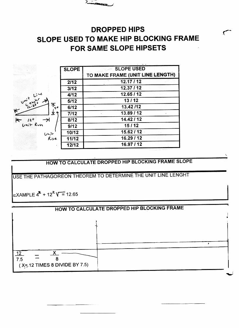
rEXAMPLE:-I- -:==
JL L 7.5 8
, X.-=", 12 TIMES 8 DIVIDE BY 7.5)
14.42 y~12.8 (X) -12-
y= 13.52 (SLOPE OF FRAME)
'~
FOR ODD SLOPES
FOR DUAL SLOPE HIPsETs-~:.!; 12- : -X ' ~,T
SIDE SLOPE -END SLOPE ~ LENGHT (X) -12y= SLOPE OF BLOCKING FRAME,
Top Related