


Languages
Pages
Legal

Scene Management
CSE 191A: Seminar on Video Game Programming
Lecture 2: Scene Management
UCSD, Spring, 2003
Instructor: Steve Rotenberg
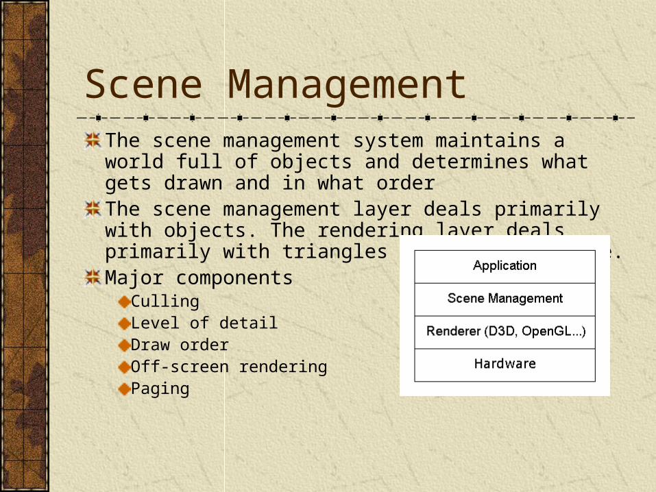
Scene ManagementThe scene management system maintains a world full of objects and determines what gets drawn and in what orderThe scene management layer deals primarily with objects. The rendering layer deals primarily with triangles and graphics state.Major components
CullingLevel of detailDraw orderOff-screen renderingPaging
Culling
Culling Definition
The term ‘cull’ means to remove from a group. A common example is to cull from a herd or flock.
In graphics, it means to determine which objects in the scene are not visible
Its usually more productive to think about it as determining which objects are visible
Culling AlgorithmsBackface cullingView volume
Bounding volume hierarchies (BV / BVH)Grid
OcclusionPortalsPotentially visible sets (PVS)Hierarchical occlusion masks (HOM)Hierarchical Z-bufferOcclusion planes
Backface Culling
Backface culling is not really part of scene management- it is a lower level feature usually built into the rendering layer
Backface culling can actually slow down rendering sometimes! Often, it is not used on the PS2
Cameras & View Volumes
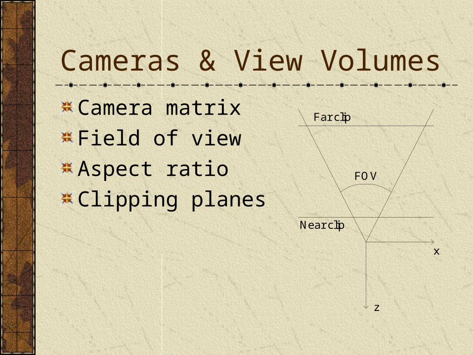
Camera matrix
Field of view
Aspect ratio
Clipping planes
x
z
FOV
Near clip
Far clip
Bounding Volume Culling
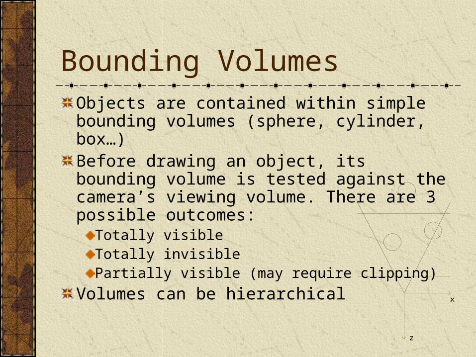
Bounding VolumesObjects are contained within simple bounding volumes (sphere, cylinder, box…)Before drawing an object, its bounding volume is tested against the camera’s viewing volume. There are 3 possible outcomes:
Totally visibleTotally invisiblePartially visible (may require clipping)
Volumes can be hierarchicalx
z
Bounding Volume Types
Sphere
Cylinder
Hot dog / capsule / lozenge
AABB: axis-aligned bounding box
OBB: oriented bounding box
Convex polyhedron
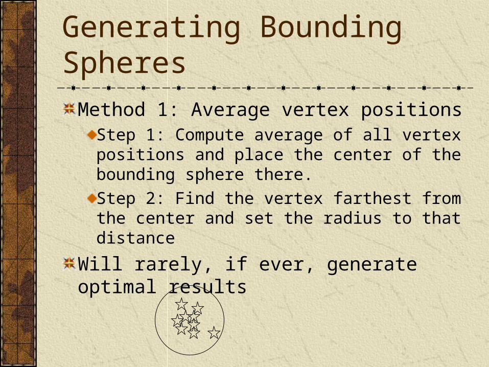
Generating Bounding Spheres
Method 1: Average vertex positionsStep 1: Compute average of all vertex positions and place the center of the bounding sphere there.
Step 2: Find the vertex farthest from the center and set the radius to that distance
Will rarely, if ever, generate optimal results
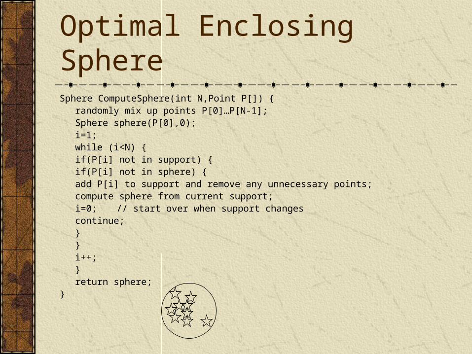
Optimal Enclosing SphereSphere ComputeSphere(int N,Point P[]) {
randomly mix up points P[0]…P[N-1];Sphere sphere(P[0],0);i=1;while (i<N) {
if(P[i] not in support) {if(P[i] not in sphere) {
add P[i] to support and remove any unnecessary points;compute sphere from current support;i=0; // start over when support changescontinue;
}}i++;
}return sphere;
}
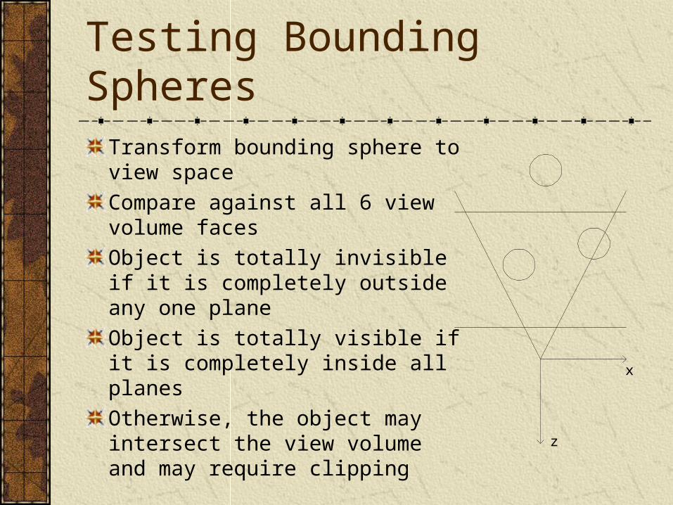
Testing Bounding SpheresTransform bounding sphere to view space
Compare against all 6 view volume faces
Object is totally invisible if it is completely outside any one plane
Object is totally visible if it is completely inside all planes
Otherwise, the object may intersect the view volume and may require clipping
x
z
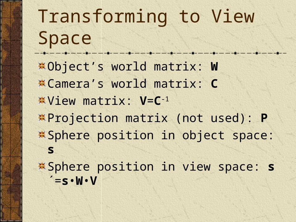
Transforming to View Space
Object’s world matrix: W
Camera’s world matrix: C
View matrix: V=C-1
Projection matrix (not used): P
Sphere position in object space: s
Sphere position in view space: s´=s•W•V
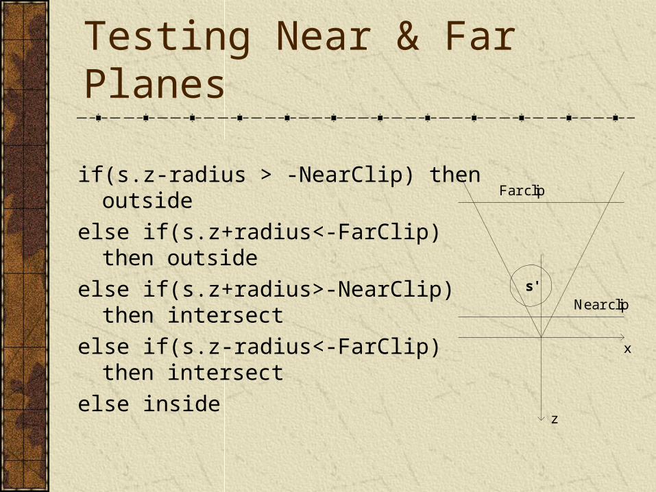
Testing Near & Far Planes
x
z
s'
Far clip
Near clip
if(s.z-radius > -NearClip) then outside
else if(s.z+radius<-FarClip) then outside
else if(s.z+radius>-NearClip) then intersect
else if(s.z-radius<-FarClip) then intersect
else inside
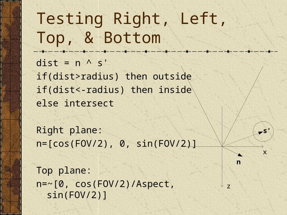
Testing Right, Left, Top, & Bottom
dist = n ^ s'
if(dist>radius) then outside
if(dist<-radius) then inside
else intersect
Right plane:
n=[cos(FOV/2), 0, sin(FOV/2)]
Top plane:
n=~[0, cos(FOV/2)/Aspect, sin(FOV/2)]
n
x
z
s'
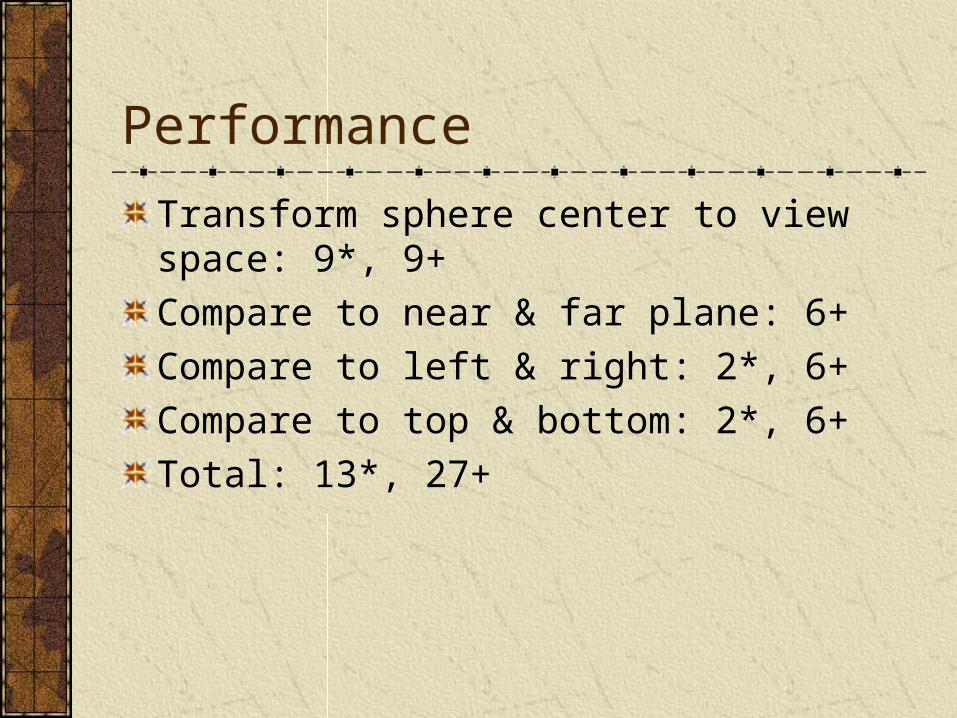
Performance
Transform sphere center to view space: 9*, 9+
Compare to near & far plane: 6+
Compare to left & right: 2*, 6+
Compare to top & bottom: 2*, 6+
Total: 13*, 27+
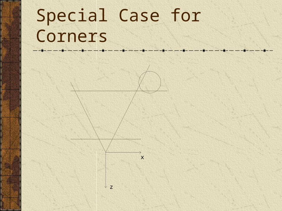
Special Case for Corners
x
z
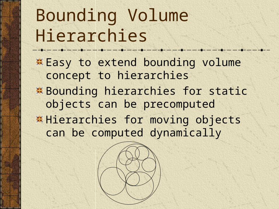
Bounding Volume Hierarchies
Easy to extend bounding volume concept to hierarchies
Bounding hierarchies for static objects can be precomputed
Hierarchies for moving objects can be computed dynamically
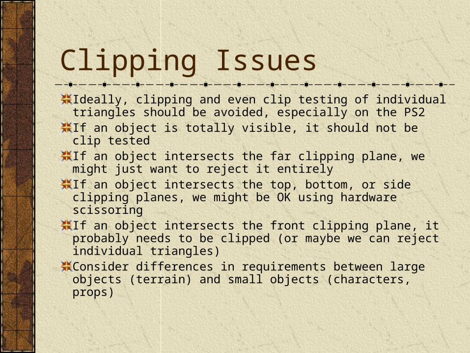
Clipping IssuesIdeally, clipping and even clip testing of individual triangles should be avoided, especially on the PS2If an object is totally visible, it should not be clip testedIf an object intersects the far clipping plane, we might just want to reject it entirelyIf an object intersects the top, bottom, or side clipping planes, we might be OK using hardware scissoringIf an object intersects the front clipping plane, it probably needs to be clipped (or maybe we can reject individual triangles)Consider differences in requirements between large objects (terrain) and small objects (characters, props)
Portal Culling
Portals
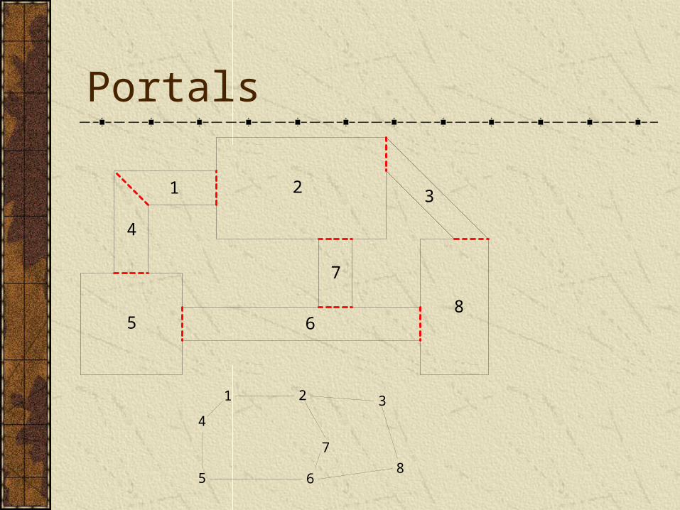
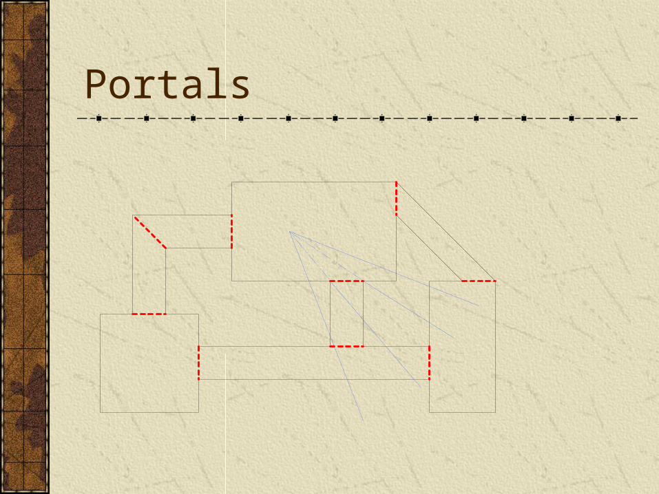
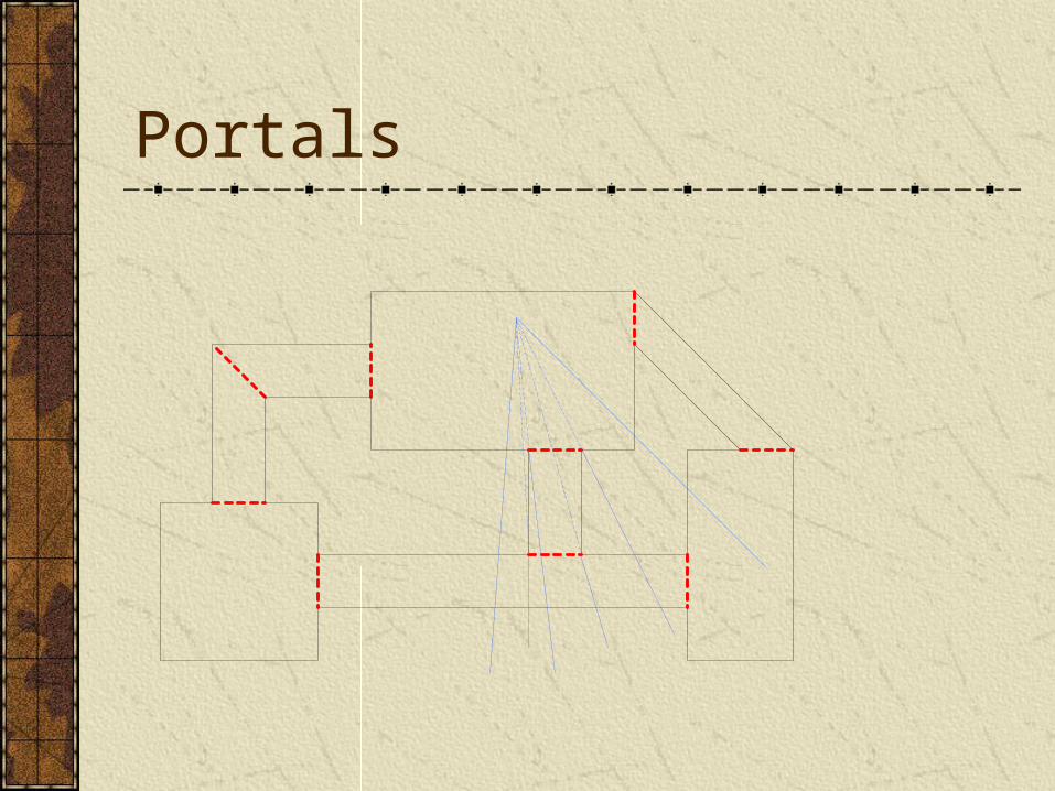
Culling algorithm designed specifically to handle interior environments (buildings, dungeons, mazes…)Can work in conjunction with bounding volume hierarchies and other culling algorithmsWorld is made up of rooms connected by rectangular portals
Portals
5
4
1 2
7
68
3
5
4
1 2
7
68
3
Portals
Portals
Portal Issues
Imposters
Portal clipping
Camera location
Combining with bounding volume culling
Moving objects
Dynamic portals (opening & closing doors)
Procedurally generating portals
PVS: Potentially Visible Sets
PVS Algorithm
Static world is broken up into individual renderable objects
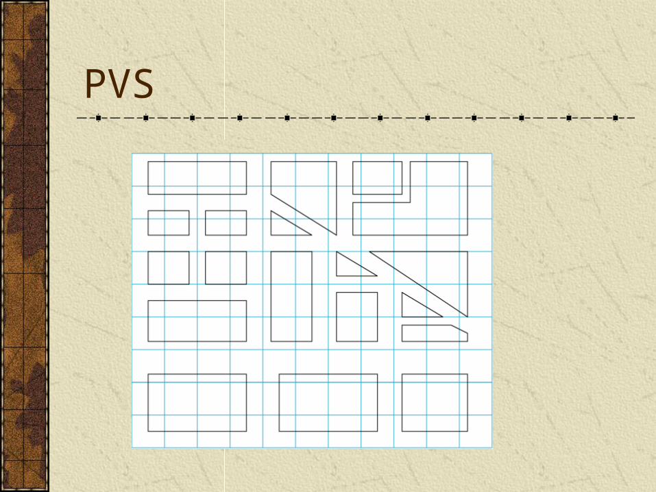
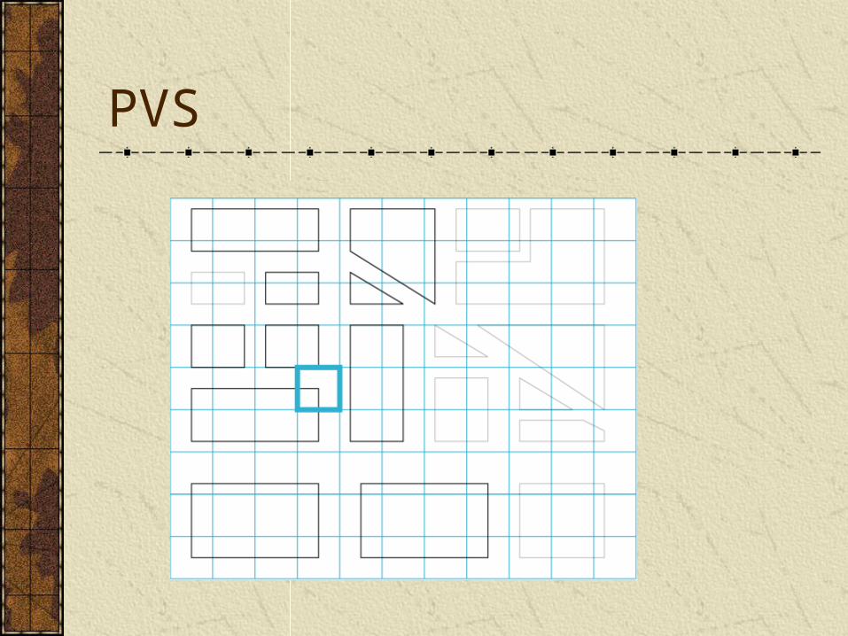
The space of all legal camera positions is broken up into zones
A precomputed table is generated that lists for each zone, all objects that might be visible
Potentially visible objects are then further tested with bounding volume culling
PVS
PVS
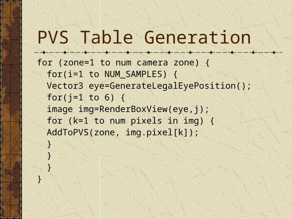
PVS Table Generationfor (zone=1 to num camera zone) {
for(i=1 to NUM_SAMPLES) {Vector3 eye=GenerateLegalEyePosition();for(j=1 to 6) {
image img=RenderBoxView(eye,j);for (k=1 to num pixels in img) {
AddToPVS(zone, img.pixel[k]);}
}}
}
PVS Issues
Overall, the algorithm can work quite well and handle very complex culling situations efficiently
However, the PVS table can get quite large and require a lot of memory
Also, defining viewing zones can be tricky
Level of Detail
Discrete LODsSeveral discrete LODs are prepared off line and dynamically switched based on simple distance comparisons (ideally it should take the camera FOV and resolution into account too)Tried and true method used for many years in flight simulationBasically no CPU overhead for algorithm itselfHardware is well adapted to rendering static display listsAdditional memory required for storing LODs, but all low LODs together are usually smaller than the high LODCan use sophisticated mesh decimation tools off line for preparing modelsIf desired, techniques exist for cross dissolving (fading) between LODsBottom line: very fast and very simple (quick & dirty)
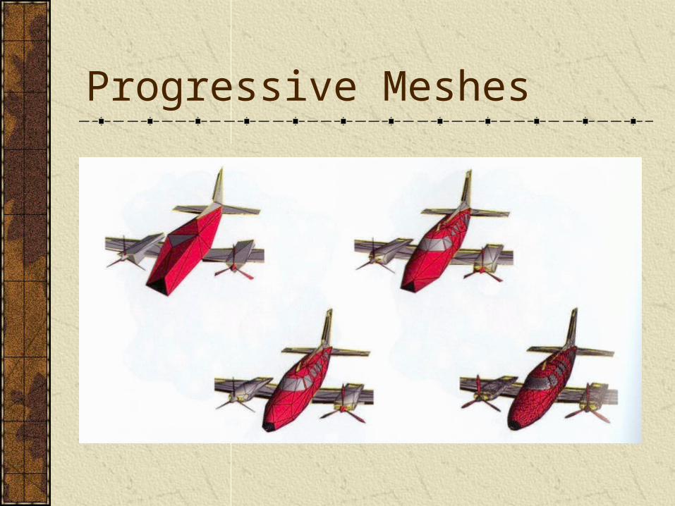
Progressive Meshes
Automated mesh decimation and dynamic reconstruction technique
Can take any model and then render it dynamically with any number of polygons (less than or equal to the original number)
Requires about 1/3 extra memory (or more, depending on details of the implementation)
Progressive Meshes
Progressive Mesh PerformanceRendering requires custom processing at the per-vertex and per-triangle level, and so the algorithm, while pretty efficient, has trouble competing with the simpler discrete LOD technique. In other words, even though it may be able to render fewer triangles, the per-triangle cost is higher, usually making the overall approach slower.Neat technology and useful research, but hasn’t been too successful in video games just yet. Future graphics hardware may have better support for progressive meshes, and so they may be more important later. Also, mesh decimation technology is still very useful in off line modeling.
Patches & Subdivision SurfacesGeometry is defined by a control mesh that explicitly describes a high order surfaceSurface is dynamically tessellated into polygons, based on camera distance and other visual quality controlsPatches & subdivision surfaces allow for smooth, rounded surfaces to be described without using tons of memoryOverall approach suffers from similar drawbacks to progressive meshes as far as its usefulness to games
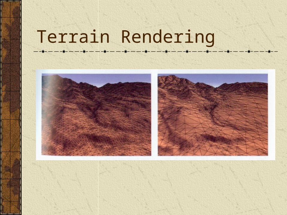
Terrain Rendering
LOD Issues
Color & lighting (normals) pops are more visible than geometry or silhouette pops
Camera is often moving and there are often many dynamic objects in the scene. This can help mask LOD transitions
Ideally, LOD should be pixel error based
More Scene Management
Load Balancing
LOD tolerances can be dynamically adjusted to provide a stable framerate
Uses timers to analyze how long the last frame took to render, then adjusts LODs so that current frame makes the most of available CPU time
Off-Screen Rendering
Imposters
Shadows
Environment maps
Full-screen effects (image distortion, blurs, color processing…)
Other visual effects…
Draw Order
Transparency
Alpha effects
Z-Buffer effects
Off-screen rendering
Caching performance
Buckets
Depth sorting
Multiple cameras
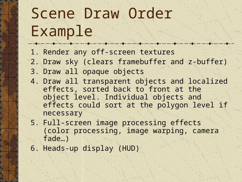
Scene Draw Order Example1. Render any off-screen textures2. Draw sky (clears framebuffer and z-buffer)3. Draw all opaque objects4. Draw all transparent objects and localized effects,
sorted back to front at the object level. Individual objects and effects could sort at the polygon level if necessary
5. Full-screen image processing effects (color processing, image warping, camera fade…)
6. Heads-up display (HUD)
Paging
Modern 3D worlds are too big to fit in game machine memory (32 megs on PS2, 64 on XBox, 24+8 on GameCube)
Data can be dynamically paged off of the DVD ROM drive
Must compete with audio & other streaming data
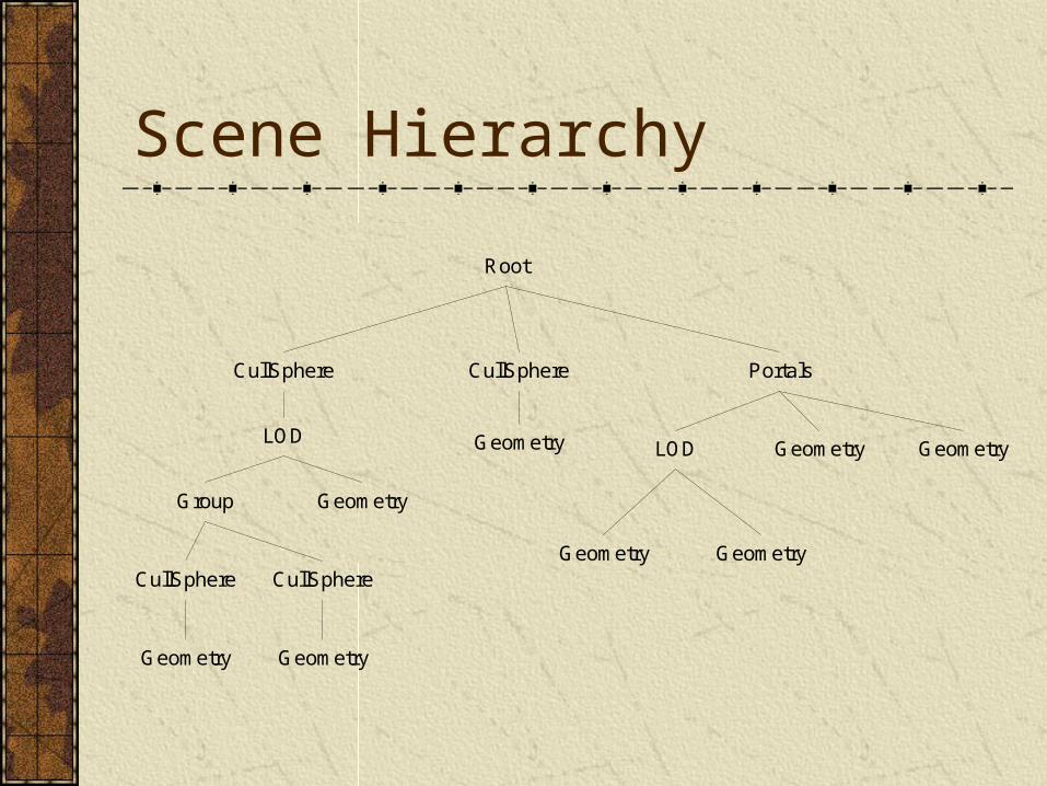
Scene Hierarchy
Root
CullSphere CullSphere
LOD
Group Geometry
CullSphere CullSphere
GeometryGeometry
Portals
Geometry LOD Geometry Geometry
Geometry Geometry
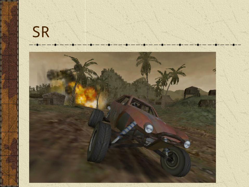
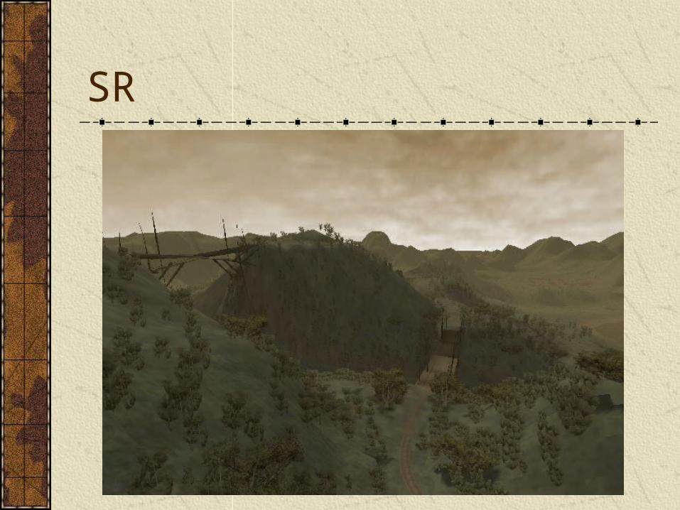
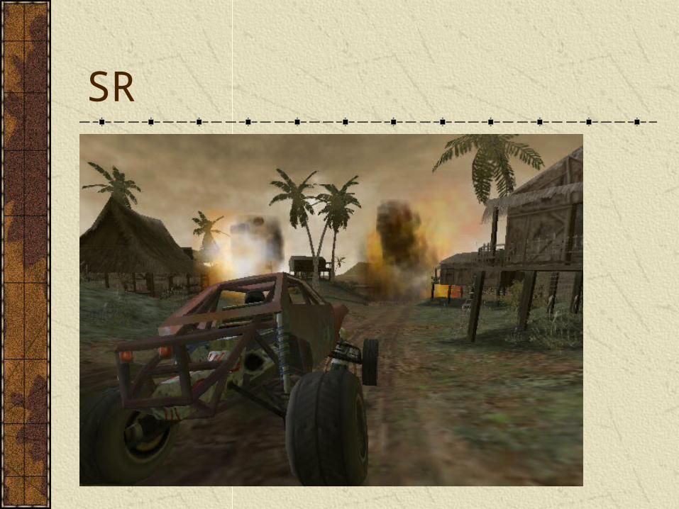
Case Study: Smuggler’s Run
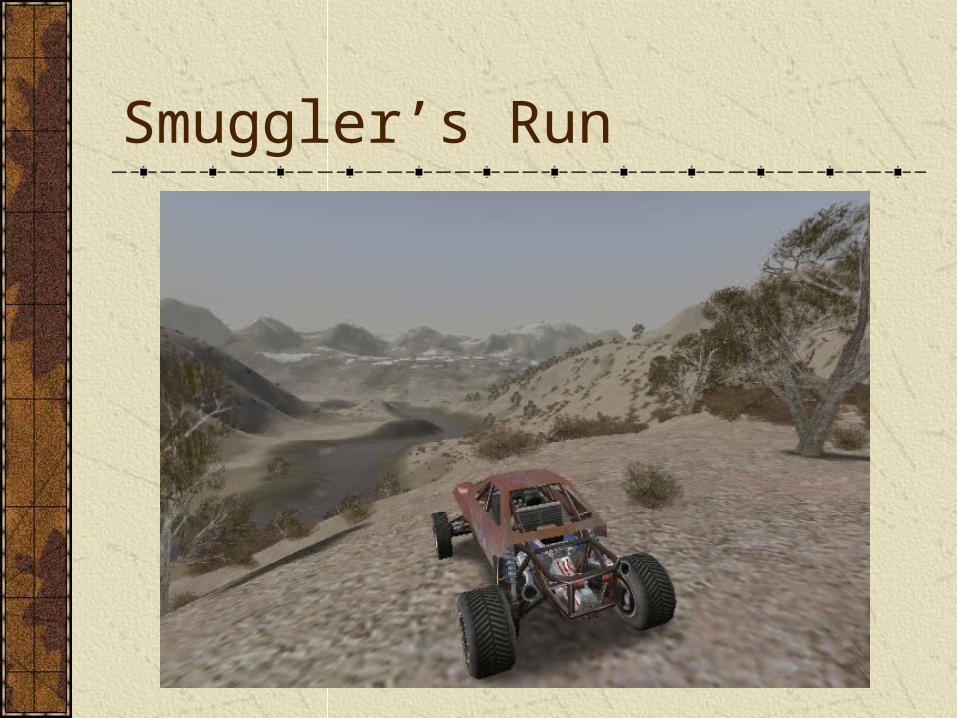
Smuggler’s Run
SR Terrain
Uniform grid, up to 1024x1024 cells
5 meter spacing for data points
32 bits per cell (height, texture ID, other misc. data)
Custom tool (Traxx) used to build terrains & set up gameplay
SR Terrain RenderingTerrain units are culled by projecting the camera view volume onto the XZ plane and using a triangle filling algorithm to find visible cells
In addition to culling, this provides full control over draw order
Terrain is rendered in two groups: distant terrain and close terrain
Distant terrain starts at 1x1 and goes down to 1/8x1/8. Distant terrain is rendered as 1 pass using a pre-made ‘satellite’ photo texture
Close terrain starts at 1x1 and goes up to 8x8 using monotonic cubic interpolation. Close terrain renders with up to 3 passes (base, roads, & shadow)
Custom PS2 microcode used to render actual 8x8 tiles
SR Level of Detail
Terrain can res up to as much as 8x8 or down to as little as 1/8x1/8
Individual objects (cars, buildings, props) can have up to 3 LODs
LOD compensates for split-screen multiplayer modes
Some dynamic load balancing is also used
SR Trees
Quad/sphere-tree stored for each type of plant
Imposter objects used for distant trees
Close trees drawn as geometry using custom instancing microcode
Alpha & z-buffer tricks used to minimize need for sorting
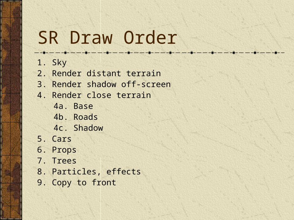
SR Draw Order1. Sky2. Render distant terrain3. Render shadow off-screen4. Render close terrain
4a. Base4b. Roads4c. Shadow
5. Cars6. Props7. Trees8. Particles, effects9. Copy to front
SR
SR
SR
Conclusion
Reference
“3D Game Engine Design” by Eberly has lot of info and algorithms for various bounding volume types“Real Time Rendering” by Moller & Haines has a lot of info on various culling schemes“Level of Detail for 3D Graphics” by Luebke, et al., has tons of info on various LOD schemes
Preview of Next Week
Collision detection
Intersection tests
Optimization structures
Pair reduction
Reading Assignment
“Real Time Rendering”Read chapter 13
Top Related