


Languages
Pages
Legal

SC7640 Auto/Manual High Resolution Sputter Coater
Operating Manual
Document Number OM-SC7640
Issue 1 (01/02)
For technical and applications advice plus our on-line shop for spares and consumable parts visit www.quorumtech.com
Quorum Technologies Ltd. Company No. 4273003. Registered offices 30/34 North Street Hailsham, East Sussex, England, BN27 1DW
Quorum Technologies Ltd is the owner and manufacture of the range of EM preparation equipment.
Unit 15A Euro Business Park New Road Newhaven East Sussex U.K. tel: ++44(0) 1273 510535 BN9 0DQ fax: ++44(0) 1273 510536 Email : [email protected] http:///www.quorumtech.com
For further information regarding any of the other products designed and manufactured by Quorum Technologies, contact your local representative or directly to Quorum Technologies at the address above.
• Carbon and Sputter Coaters
• Plasma Reactor for ashing and etching
• High Vacuum Bench Top Evaporators
• Cryo Transfer Systems
• Critical Point Dryers
• Service and Spares
For technical and applications advice plus our on-line shop for spares and consumable parts visit www.quorumtech.com
Disclaimer The components and packages described in this document are mutually compatible and guaranteed to meet or exceed the published performance specifications. No performance guarantees, however, can be given in circumstances where these component packages are used in conjunction with equipment supplied by companies other than Quorum Technologies.
OM-SC7640 Contents
Issue 1 3 SC7640 Sputter Coater
1 Contents 1.1 Manual Layout
This Operating Manual is divided up into the following major section, each chapter dealing with specific topics, as follows:
Chapter 1 - Contents
Chapter 2 - Health and Safety
General section which applies to all Quorum Technologies Polaron products detailing the very important issues of Health and Safety applicable when using sample preparation equipment.
Chapter 3 - Introduction
Introduces this manual.
Chapter 4 - General Description
Identifies each of the equipment items and provides an overview of their functions and how they work.
Chapter 5 - Installation
Instructions on how this Instrument should be installed and the connections which should be made between the equipment items.
Chapter 6 - Operation
Instructions on how to start-up and run the instrument.
Chapter 7 - Maintenance
Instructions on how to check the system is functioning correctly, and how to change consumable items. Details of appropriate spare parts.
Chapter 8 - Fault Finding
Information on how to identify faults in the system and how to rectify these faults.
Chapter 9 - Agents
List of main agents supporting the Quorum Technologies product range.
Chapter 10 - Index
Contents OM-SC7640
SC7640 Sputter Coater 4 Issue 1
1.2 Chapter Contents Chapter 1 - Contents ................................................................................................ 3
1.1 Manual Layout ................................................................................ 3 1.2 Chapter Contents ........................................................................... 4 1.3 Illustrations ..................................................................................... 6 1.4 Tables ............................................................................................ 6
Chapter 2 - Health and Safety ................................................................................. 7
2.1 Control of Substances Hazardous to Health (COSHH) ................. 7 2.2 Safety Policy ................................................................................... 7 2.3 Conformity ...................................................................................... 7 2.4 Servicing ........................................................................................ 8 2.4.1 Disclaimer ............................................................................... 8 2.4.2 Operators and Service Engineers .......................................... 8 2.5 Hazard Signals and Signs .............................................................. 8 2.5.1 Hazard Signal Words ............................................................. 8 2.5.2 Hazard Labels used on Equipment ........................................ 8 2.5.3 Hazard Warning Labels used in Equipment Manuals ............ 9 2.5.4 Instrument Functionality Signs ............................................... 9 2.5.5 Serious Damage to Instruments ............................................. 9 2.5.6 Hazard to Operator ................................................................. 9 2.6 Risk Analysis .................................................................................. 10 2.6.1 Personal Operational Risks .................................................... 10 2.6.2 Hazardous Materials ............................................................... 10 2.7 Good Working Practices ................................................................ 11 2.8 SC7640 Sputter Coater Specific Safety Hazards ........................... 11 2.8.1 Contamination ........................................................................ 11
Chapter 3 - Introduction............................................................................................ 12 3.1 Return of Goods ............................................................................. 12 3.2 Returns Procedure ......................................................................... 12
Chapter 4 - Description ............................................................................................ 13 4.1 Equipment ...................................................................................... 13 4.1.1 Accessories ............................................................................ 13 4.1.2 Optional Items ........................................................................ 13 4.1.3 Optional Accessories .............................................................. 14 4.2 Overview ........................................................................................ 15 4.3 Technical Specification .................................................................. 15 4.3.1 SC7640 Sputter Coater Specification ..................................... 15 4.4 Physical Description ....................................................................... 16 4.4.1 Operational Description .......................................................... 17 4.4.2 Pumping Requirements .......................................................... 17 4.5 Interlocks ........................................................................................ 17 4.6 SC7640 Panel Details .................................................................... 18 4.6.1 SC7640, Front Panel Controls ................................................ 18 4.6.2 SC7640, Rear Panel Connections .......................................... 19
Chapter 5 - Installation ............................................................................................. 20
5.1 Unpacking Checklist ...................................................................... 20 5.1.1 Preparation ............................................................................. 20 5.2 SC7640 Installation ........................................................................ 21 5.2.1 Connections ............................................................................ 21 5.3 Installation of Optional Accessories ............................................... 22 5.3.1 FT7607 Crystal Holder Stage ................................................. 23 5.3.2 RC7606 Rotary Planetary Stage ............................................ 23 5.3.3 WS7608 Water Cooled Stage................................................. 23
OM-SC7640 Contents
Issue 1 5 SC7640 Sputter Coater
Chapter 6 - Operation .............................................................................................. 24 6.1 Test Procedure ............................................................................... 24 6.2 Coating Process ............................................................................. 26 6.3 Coating Specimens ........................................................................ 26 6.3.1 Coating in Manual Mode - High Resolution ............................ 26 6.3.2 Coating in Manual Mode - Routine ......................................... 28 6.3.3 Coating in Automatic Mode .................................................... 29 6.4 Sputtering Rates ............................................................................ 30
Chapter 7 - Maintenance .......................................................................................... 31
7.1 Maintenance - General .................................................................. 31 7.2 Cleaning ......................................................................................... 31 7.2.1 Vacuum Chamber Cleaning ................................................... 31 7.3 Target Replacement ...................................................................... 32 7.3.1 Target Removal ...................................................................... 32 7.3.2 Refit New Target .................................................................... 32 7.4 No Plasma Current ........................................................................ 33 7.5 Spare Parts ..................................................................................... 33
Chapter 8 - Fault Finding ......................................................................................... 34
8.1 Trouble Shooting / Fault Finding .................................................... 34 8.2 Fault Prevention ............................................................................. 34
Chapter 9 - Agents ................................................................................................... 35
Chapter 10 - Index .................................................................................................... 36
Contents OM-SC7640
SC7640 Sputter Coater 6 Issue 1
1.3 Illustrations Figure 2.1 - Hazard Warning Symbols ....................................................................... 8 Figure 2.2 - International Warning Symbols ............................................................... 9 Figure 2.3 - Typical Signs as shown in this Manual .................................................... 9 Figure 2.4 - Typical Signs as shown in this Manual ................................................... 9 Figure 2.5 - Typical Warnings, as shown in this Manual ............................................ 9 Figure 4.1 - SC7640 Sputter Coater ........................................................................... 16 Figure 4.2 - SC7640 Sputter Coater Operation........................................................... 17 Figure 4.3 - SC7640 Sputter Coater, Front Panel Controls ........................................ 18 Figure 4.4 - SC7640 Sputter Coater, Rear Panel Connections .................................. 19 Figure 5.1 - SC7640 Connections .............................................................................. 22 Figure 6.1 - Sputtering Rates ..................................................................................... 30 Figure 7.1 - Target Replacement ............................................................................... 32
1.4 Tables Table 2.1 - Personal Operational Risks ...................................................................... 10 Table 4.1 - SC7640 Sputter Coater, Front Panel Control Descriptions ...................... 18 Table 4.2 - SC7640 Sputter Coater, Rear Panel Connection Descriptions ................ 19 Table 7.1 - Spare Parts .............................................................................................. 33 Table 8.1 - Trouble Shooting ...................................................................................... 34 Table 8.2 - Fault Prevention ....................................................................................... 34 Table 9.1 - List of Agents Supporting Quorum Technologies Products ..................... 35
OM-SC7640 Health and Safety
Issue 1 7 SC7640 Sputter Coater
2 Health and Safety Safety is very important when using any instrumentation and this chapter should be read by all users of our equipment.
This section of the Manual applies to all surface analysis and surface preparation equipment supplied by Quorum Technologies Polaron range of products, not just the particular instrument for which the manual refers.
Included in this chapter are details on warning notations, good working practices and information on European Community (EC) legislation regarding “Control Of Substances Hazardous to Health” (COSHH) and risk analysis.
2.1 Control of Substances Hazardous to Health (COSHH) The E.C. legislation regarding the “Control of Substances Hazardous to Health” requires Quorum Technologies to monitor and assess every substance entering or leaving their premises. Consequently any returned goods of whatever nature must be accompanied by a declaration form available from Quorum Technologies, reference number SP-100. Without this declaration Quorum Technologies reserves the right not to handle the substance/item. Also in accordance with E.C. regulations we will supply on request hazard data sheets for substances used in our instruments.
2.2 Safety Policy This section contains important information relating to all health and safety aspects of the equipment. As such it should be read, and understood, by all personnel using the instrument whether as an operator or in a service capacity.
Quorum Technologies is committed to providing a safe working environment for its employees and those that use it's equipment and conducts its business responsibly, and in a manner designed to protect the health and safety of its customers, employees and the public at large. It also seeks to minimise any adverse effects that its activities may have on the environment.
Quorum Technologies regularly reviews its operations to make environmental, health and safety improvements in line with UK and European Community legislation.
The equipment has been designed as free-standing bench mounted instruments. Quorum Technologies cannot be held responsible for any damage, injury or consequential loss arising from the use of its equipment for any other purposes, or any unauthorised modifications made to the equipment.
All service work carried out on the equipment should only be undertaken by suitably qualified personnel. Quorum Technologies is not liable for any damage, injury or consequential loss resulting from servicing by unqualified personnel. Quorum Technologies will also not be liable for damage, injury or consequential loss resulting from incorrect operation of the instrument or modification of the instrument.
2.3 Conformity This instrument is supplied in a form that complies with the protection requirements of the EC Electromagnetic Compatibility Directive 89/336/EEC and the essential health and safety requirements of the low voltage directive 72/23/EEC both as amended by 92/31/EEC. Any modifications to the equipment, including electronics or cable layout may affect the compliance with these directives.
Health and Safety OM-SC7640
SC7640 Sputter Coater 8 Issue 1
2.4 Servicing
2.4.1 Disclaimer
All service work on the equipment should be carried out by qualified personnel. Quorum Technologies cannot be liable for damage, injury or consequential loss resulting from servicing from unqualified personnel. Quorum Technologies will also not be liable for damage, injury or consequential loss resulting from incorrect operation of the instrument or modification of the instrument.
2.4.2 Operators and Service Engineers A normal operator of the equipment will not be trained in or qualified for service work on the equipment and may cause a hazard to himself/herself or others if such work is attempted. Operators should therefore restrict themselves to the normal operation of the equipment and not by removing covers from the electronic equipment or dismantling of the instruments.
Service Engineers who are suitably trained to assess and isolate electrical, mechanical and vacuum hazards should be the only personnel who access the equipment.
2.5 Hazard Signals and Signs
2.5.1 Hazard Signal Words
The standard three hazard signal words are defined as follows:
◆ DANGER - imminently hazardous situation or unsafe practice that, if not avoided, will result in death or severe injury.
◆ WARNING - potentially hazardous situation or unsafe practice that, if not avoided, could result in death or severe injury.
◆ CAUTION - potentially hazardous situation or unsafe practice that, if not avoided, may result in minor or moderate injury or damage to equipment.
2.5.2 Hazard Labels used on Equipment
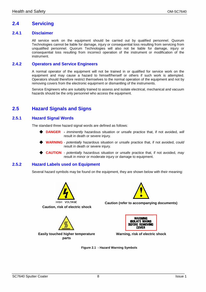
Several hazard symbols may be found on the equipment, they are shown below with their meaning:
Caution, risk of electric shock
Caution (refer to accompanying documents)
Easily touched higher temperature
parts
Warning, risk of electric shock
Figure 2.1 - Hazard Warning Symbols
OM-SC7640 Health and Safety
Issue 1 9 SC7640 Sputter Coater
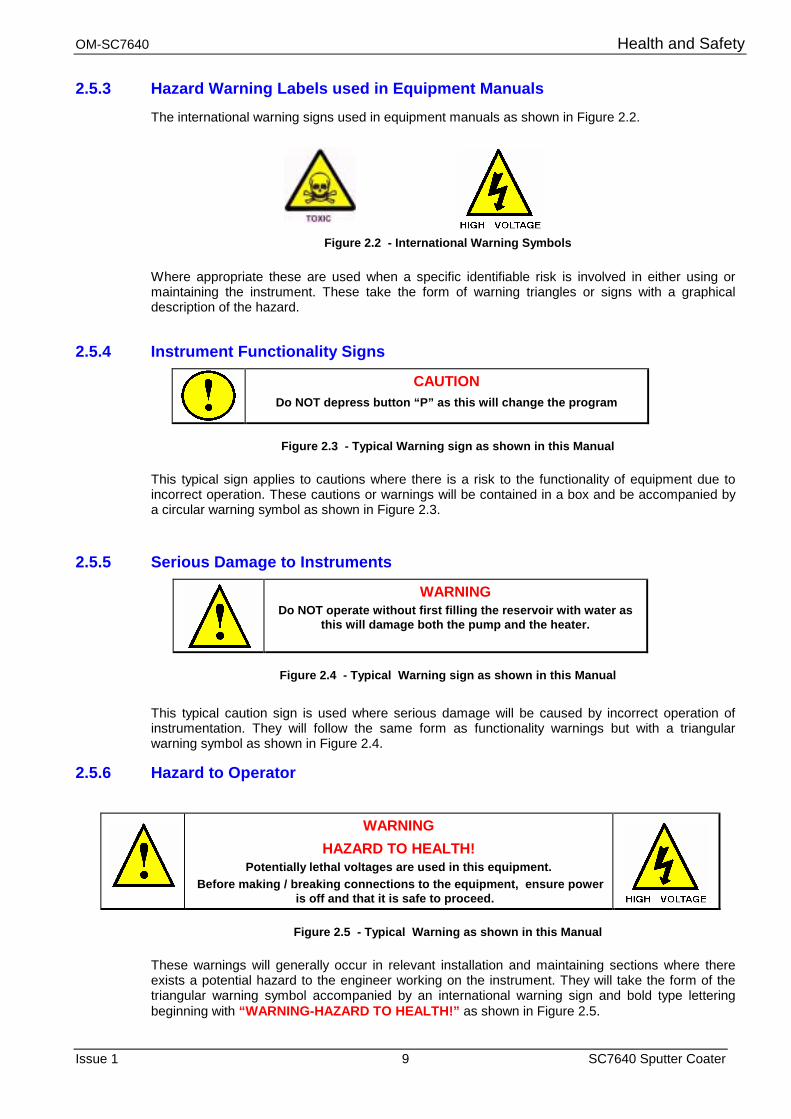
2.5.3 Hazard Warning Labels used in Equipment Manuals The international warning signs used in equipment manuals as shown in Figure 2.2.
Figure 2.2 - International Warning Symbols
Where appropriate these are used when a specific identifiable risk is involved in either using or maintaining the instrument. These take the form of warning triangles or signs with a graphical description of the hazard.
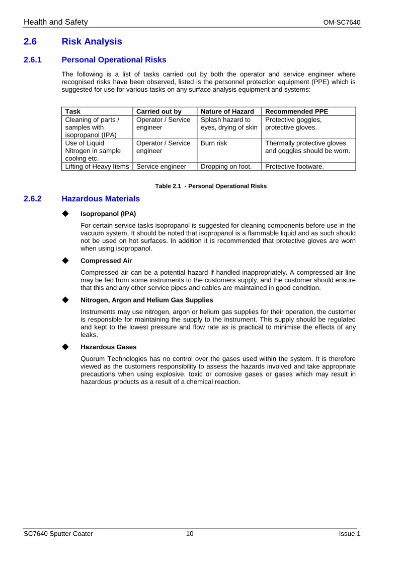
2.5.4 Instrument Functionality Signs
CAUTION Do NOT depress button “P” as this will change the program
Figure 2.3 - Typical Warning sign as shown in this Manual
This typical sign applies to cautions where there is a risk to the functionality of equipment due to incorrect operation. These cautions or warnings will be contained in a box and be accompanied by a circular warning symbol as shown in Figure 2.3.
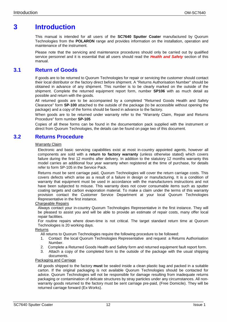
2.5.5 Serious Damage to Instruments
WARNING Do NOT operate without first filling the reservoir with water as
this will damage both the pump and the heater.
Figure 2.4 - Typical Warning sign as shown in this Manual
This typical caution sign is used where serious damage will be caused by incorrect operation of instrumentation. They will follow the same form as functionality warnings but with a triangular warning symbol as shown in Figure 2.4.
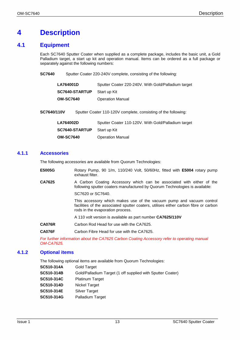
2.5.6 Hazard to Operator
WARNING HAZARD TO HEALTH!
Potentially lethal voltages are used in this equipment. Before making / breaking connections to the equipment, ensure power
is off and that it is safe to proceed.
Figure 2.5 - Typical Warning as shown in this Manual
These warnings will generally occur in relevant installation and maintaining sections where there exists a potential hazard to the engineer working on the instrument. They will take the form of the triangular warning symbol accompanied by an international warning sign and bold type lettering beginning with “WARNING-HAZARD TO HEALTH!” as shown in Figure 2.5.
Health and Safety OM-SC7640
SC7640 Sputter Coater 10 Issue 1
2.6 Risk Analysis
2.6.1 Personal Operational Risks
The following is a list of tasks carried out by both the operator and service engineer where recognised risks have been observed, listed is the personnel protection equipment (PPE) which is suggested for use for various tasks on any surface analysis equipment and systems:
Task Carried out by Nature of Hazard Recommended PPE Cleaning of parts / samples with isopropanol (IPA)
Operator / Service engineer
Splash hazard to eyes, drying of skin
Protective goggles, protective gloves.
Use of Liquid Nitrogen in sample cooling etc.
Operator / Service engineer
Burn risk Thermally protective gloves and goggles should be worn.
Lifting of Heavy Items Service engineer Dropping on foot. Protective footware.
Table 2.1 - Personal Operational Risks
2.6.2 Hazardous Materials
◆ Isopropanol (IPA)
For certain service tasks isopropanol is suggested for cleaning components before use in the vacuum system. It should be noted that isopropanol is a flammable liquid and as such should not be used on hot surfaces. In addition it is recommended that protective gloves are worn when using isopropanol.
◆ Compressed Air
Compressed air can be a potential hazard if handled inappropriately. A compressed air line may be fed from some instruments to the customers supply, and the customer should ensure that this and any other service pipes and cables are maintained in good condition.
◆ Nitrogen, Argon and Helium Gas Supplies
Instruments may use nitrogen, argon or helium gas supplies for their operation, the customer is responsible for maintaining the supply to the instrument. This supply should be regulated and kept to the lowest pressure and flow rate as is practical to minimise the effects of any leaks.
◆ Hazardous Gases
Quorum Technologies has no control over the gases used within the system. It is therefore viewed as the customers responsibility to assess the hazards involved and take appropriate precautions when using explosive, toxic or corrosive gases or gases which may result in hazardous products as a result of a chemical reaction.

OM-SC7640 Health and Safety
Issue 1 11 SC7640 Sputter Coater
2.7 Good Working Practices
It is essential that good hygienic working practices are adopted at all times especially in an ultra high vacuum or cleanroom environment and are generally of the “Common sense” type. Some simple good practice rules are:
◆ If in doubt don't.
◆ If in doubt ask.
◆ When handling solvents wear face mask, gloves, apron and work only in a well ventilated area.
◆ Mop up any spillages immediately.
◆ When handling or decanting mineral oils wear protective clothing.
◆ Aerosols of mineral oils, such as that produced by gas ballasting, can prove to be hazardous and an exhaust is recommended.
◆ Before attempting to service electrical apparatus, isolate from the mains.
◆ Treat all unknown substances as hazardous.
◆ Dispose of substances in an appropriate manner.
◆ Use the correct tool for the job.
◆ Keep a straight back and bend from the knees when lifting heavy objects.
◆ Wear protective clothing when using liquid nitrogen.
◆ Affix pressurised gas cylinders firmly to walls or racks. Use the correct regulating valves on gas cylinders and always transport cylinders using the appropriate specialist trolley.
◆ Obey safety regulations regarding lifts, hoists and machine tools.
◆ Always make sure you understand a procedure well before attempting it for the first time.
2.8 SC7640 Specific Safety Hazards The following Safety Hazards are specific to the SC7640 Sputter Coater.
WARNING HAZARD TO HEALTH!
The Power Supply used in the Model SC7640 unit can operate at up to 3000V D.C
HAZARDOUS VOLTAGE OUTPUTS of up to 3000V. D.C.
2.8.1 Contamination
Contamination can seriously affect the sputtering process. To reduce the possibility of contamination by airborne particles, minimise the time the vacuum chamber is open to the atmosphere.
Introduction OM-SC7640
SC7640 Sputter Coater 12 Issue 1
3 Introduction This manual is intended for all users of the SC7640 Sputter Coater manufactured by Quorum Technologies from the POLARON range and provides information on the installation, operation and maintenance of the instrument.
Please note that the servicing and maintenance procedures should only be carried out by qualified service personnel and it is essential that all users should read the Health and Safety section of this manual.
3.1 Return of Goods If goods are to be returned to Quorum Technologies for repair or servicing the customer should contact their local distributor or the factory direct before shipment. A "Returns Authorisation Number" should be obtained in advance of any shipment. This number is to be clearly marked on the outside of the shipment. Complete the returned equipment report form, number SP106 with as much detail as possible and return with the goods. All returned goods are to be accompanied by a completed "Returned Goods Health and Safety Clearance" form SP-100 attached to the outside of the package (to be accessible without opening the package) and a copy of the forms should be faxed in advance to the factory. When goods are to be returned under warranty refer to the “Warranty Claim, Repair and Returns Procedure” form number SP-105 Copies of all these forms can be found in the documentation pack supplied with the instrument or direct from Quorum Technologies, the details can be found on page two of this document.
3.2 Returns Procedure Warranty Claim
Electronic and basic servicing capabilities exist at most in-country appointed agents, however all components are sold with a return to factory warranty (unless otherwise stated) which covers failure during the first 12 months after delivery. In addition to the statutory 12 months warranty this model carries an additional four year warranty when registered at the time of purchase, for details refer to form SP-105 in the Service Pack. Returns must be sent carriage paid, Quorum Technologies will cover the return carriage costs. This covers defects which arise as a result of a failure in design or manufacturing. It is a condition of warranty that equipment must be used in accordance with the manufacturers instructions and not have been subjected to misuse. This warranty does not cover consumable items such as sputter coating targets and carbon evaporation material. To make a claim under the terms of this warranty provision contact the Customer Service Department at your local Quorum Technologies Representative in the first instance.
Chargeable Repairs Always contact your in-country Quorum Technologies Representative in the first instance. They will be pleased to assist you and will be able to provide an estimate of repair costs, many offer local repair facilities. For routine repairs where down-time is not critical. The target standard return time at Quorum Technologies is 20 working days.
Returns All returns to Quorum Technologies require the following procedure to be followed: 1. Contact the local Quorum Technologies Representative and request a Returns Authorisation
Number. 2. Complete a Returned Goods Health and Safety form and returned equipment fault report form. 3. Attach a copy of the completed form to the outside of the package with the usual shipping
documents. Packaging and Carriage
All goods shipped to the factory must be sealed inside a clean plastic bag and packed in a suitable carton. If the original packaging is not available Quorum Technologies should be contacted for advice. Quorum Technologies will not be responsible for damage resulting from inadequate returns packaging or contamination of delicate structures by stray particles under any circumstances. All non-warranty goods returned to the factory must be sent carriage pre-paid, (Free Domicile). They will be returned carriage forward (Ex-Works).
OM-SC7640 Description
Issue 1 13 SC7640 Sputter Coater
4 Description 4.1 Equipment
Each SC7640 Sputter Coater when supplied as a complete package, includes the basic unit, a Gold Palladium target, a start up kit and operation manual. Items can be ordered as a full package or separately against the following numbers: SC7640 Sputter Coater 220-240V complete, consisting of the following:
LA764001D Sputter Coater 220-240V. With Gold/Palladium target
SC7640-STARTUP Start up Kit
OM-SC7640 Operation Manual
SC7640/110V Sputter Coater 110-120V complete, consisting of the following:
LA764002D Sputter Coater 110-120V. With Gold/Palladium target
SC7640-STARTUP Start up Kit
OM-SC7640 Operation Manual
4.1.1 Accessories The following accessories are available from Quorum Technologies: E5005G Rotary Pump, 90 1/m, 110/240 Volt, 50/60Hz, fitted with E5004 rotary pump
exhaust filter.
CA7625 A Carbon Coating Accessory which can be associated with either of the following sputter coaters manufactured by Quorum Technologies is available:
SC7620 or SC7640.
This accessory which makes use of the vacuum pump and vacuum control facilities of the associated sputter coaters, utilises either carbon fibre or carbon rods in the evaporation process.
A 110 volt version is available as part number CA7625/110V
CA076R Carbon Rod Head for use with the CA7625.
CA076F Carbon Fibre Head for use with the CA7625.
For further information about the CA7625 Carbon Coating Accessory refer to operating manual OM-CA7625.
4.1.2 Optional items The following optional items are available from Quorum Technologies: SC510-314A Gold Target SC510-314B Gold/Palladium Target (1 off supplied with Sputter Coater) SC510-314C Platinum Target SC510-314D Nickel Target SC510-314E Silver Target SC510-314G Palladium Target
Description OM-SC7640
SC7640 Sputter Coater 14 Issue 1
4.1.3 Optional Accessories
The SC7640 Sputter Coater is available with three optional stage accessories, only one of which may be fitted at a time. These accessories will normally be factory fitted at the time of ordering, the required option must be stated at this time. If more than one of these options are ordered the others will be supplied as kits. Alternatively, the Sputter Coater can be returned to the factory for upgrading. Methods of fitting these units can be found in the Installation Section, Paragraph 5.3.
Film Thickness Monitor
The standard stage can be replaced with an adjustable height stage incorporating a crystal holder. This enables the user to monitor and control the coating thickness with the optional FT7690 Film Thickness monitor.
The optional FT7690 Film Thickness Monitor monitors and controls thickness of the sputter coater by over-riding the timer when plugged into the unit. The deposition thickness is selected and controlled to 0.1 nm with a range of 999.9 nm. The density of the evaporant is selected and the percentage of the crystal useful life can be displayed. The crystal life is typically 2-4 microns for gold. The unit operates using an oscillating 5MHz crystal and monitoring the change of resonant frequency as the crystal becomes loaded with evaporant.
The Film Thickness Monitor is supplied as two packages:
FT7690 Film Thickness Monitor complete with Oscillator.
FT7607 Crystal Holder Stage.
Rotary Planetary Stage
The standard stage can be replaced with a rotary planetary stage. This is of particular interest for users with open pore high surface area samples and for carbon evaporation. The power supply for the rotary stage is built into the system as standard.
RC7606 A kit of parts to add a rotary planetary specimen stage to a SC7640 Sputter Coater, the kit contains: Rotary Planetary Stage, Motor, Drive Components and Fixings.
Water Cooled Stage
The standard stage can be replaced with a water cooled stage. Cooled water can be circulated to lower the stage temperature. This reduced temperature should be kept above the Dew point to avoid condensation of atmospheric moisture whilst the stage is open to the atmosphere. This will result in excessive pump down times on re-evacuation and possible sample damage.
WS7608 A kit of parts to add a water cooled specimen stage to a SC7640 Sputter Coater, the kit contains: Water Cooled Stage, Inlet and Outlet Connectors, Piping and Fixings.
OM-SC7640 Description
Issue 1 15 SC7640 Sputter Coater
4.2 Overview The SC7640 Sputter Coater is a extremely versatile sputter coater designed to produce fine grain “cool” coatings. At the heart the SC7640 has an advanced annular style magnetron head which is designed to ensure even coatings over a wide area it is fitted with a simple to replace disc target (gold/palladium is supplied as standard, but others metals are available as options). This enables thin sample coatings of 2-3 nm to be achieved without charging effects being experienced in the SEM.
The sputter head when operated at 800V DC gives high resolution coatings. Alternatively standard coatings with rapid deposition can be achieved at high voltages. Coating time is controlled with a 999 second timer. Pressure levels and plasma currents are monitored by analogue meters. The standard system has an adjustable height sample stage; a water cooled stage, rotary planetary stage or a film thickness monitor are optional.
The SC7640 can be used in two modes: automatic for standard coatings or manual operation with complete control of all parameters – essential for the production of high resolution films.
The 150mm (6") diameter Pyrex cylinder is mounted on an aluminium collar and sealed “L” shaped seals. The small vacuum chamber means pump down times and cycle times are fast; it also allows a small economical rotary to be used. The sample stage is height adjustable over a large range and can easily be removed to accommodate large samples.
When the SC7640 is operated in manual mode, pump down, purge and flush are still carried out automatically, this maintains system versatility bet releases the user from time consuming mundane operations. For Field Emission SEM and high resolution studies the platinum target (SC510-314C) is recommended.
For SEM X-ray microanalysis applications the SC7640 can be simply converted to deposit carbon by the addition of an optional carbon evaporation attachment, consisting of a switchable Voltage power supply (CA7625) and a Carbon fibre head (CA076F) or Carbon rod head (CA076R).
The SC7640 comes complete with a one metre of 20mm bore vacuum hose and fittings and requires only the addition of a rotary pump with a capacity of 50 litres / minute or greater (see "options and accessories”).
4.3 Technical Specification
4.3.1 SC7640 Sputter Coater Specification
Unit dimensions: 455mm wide x 375mm deep x 375mm high (including vacuum chamber).
Vacuum chamber: 150mm internal diameter x 135mm high.
Weight: 35 kg (77lbs).
Power requirement: Available for either 230V (13 amp) or 110V (20 amp) operation at 50/60Hz.
Target distance: Normally 45mm (adjustable).
Power supply output: Normal operation is up to 2400V D.C. at 20mA. or 800V D.C at 10mA. Maximum output 2800V D.C.
System control: Automatic or manually by a 999 second timer with 1second resolution.
Pumping requirements: Pump to evacuate >10-3 mbar.
Sputtering rates: Refer to Table 6.1, example with a gold/palladium target and current of 20mA and current of 2.5kV a rate of 10nm per minute is achieved.
Coating thickness: Dependant on time and current, normally between 50 and 300 Angstrom (∑) units for SEM investigations, but will typically be in the region of 1 - 20 nanometers, thin coatings of 2-3 nm can be achieved without charging effects being experienced in the SEM.
Coating uniformity: Better than 10%.
Gas medium: Argon.
Description OM-SC7640
SC7640 Sputter Coater 16 Issue 1
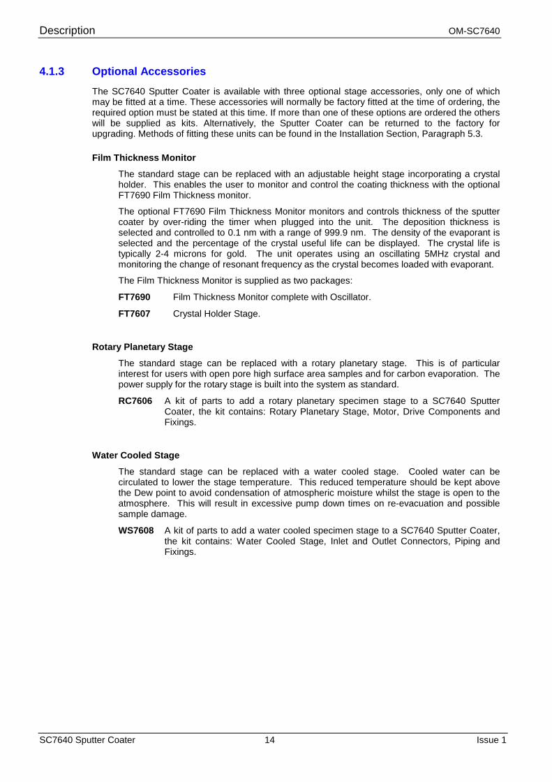
4.4 Physical Description The SC7640 Sputter Coater is a simple to operate magnetron sputtering system designed to be used for coating Scanning Electron Microscopy (SEM) specimens. The system can be operated in manual or automatic mode. In the manual mode, pump down, purge and flush are still carried out automatically. The manual control of sputtering simplifies the control of the parameters essential for the production of high resolution films.
The SC7640 Sputter Coater is comprised of two main parts:
The Cabinet assembly The Vacuum chamber
The cabinet assembly, which contains a high voltage power supply, vacuum gauging and manifold, supports the vacuum chamber. Mounted on the front panel of the cabinet are switches and meters, which provide the operator interface to the system. All service connections to the system are made via the rear panel. The cabinet is constructed in a manner to comply with the European EMC regulations.
The vacuum chamber is formed by the top plate assembly, the glass work chamber and the baseplate assembly mounted on the top panel of the cabinet. The integrity of the vacuum is maintained by circular "L" gaskets either end of the work chamber.
The top plate supports the cathode (target) and magnetic deflection system incorporating a dark space shield, which confines the plasma below the target. Flying leads (secured to the top plate), provide the necessary electrical and gas connections between the top plate and the rear panel connectors of the cabinet. The top plate is supported from a hinged pillar fixed to the rear panel. The hinging facilitates the loading and removal of samples from the work chamber and also aids the changing and replacement of targets.
The SC7640 Sputter Coater produces fine grain coating with maximum versatility. The annular design of the magnetron sputter head ensures even coating over a wide area, which enables thin coatings of 2-3 nm to be achieved without charging effects being experienced in the SEM. The SC7640 sputter head, when operated at 800V DC gives high resolution coatings or standard coatings deposited rapidly at 2400V DC. Coating time is controlled by a three digit electronic timer with 1 second resolution. The vacuum level and plasma current are monitored by analogue meters. The standard adjustable height specimen stage can be replaced by an optional water cooled stage (WC7608), a rotary planetary stage (RC7606) or a FTM stage (FT7607). With the optional FTM stage, the coating thickness can be controlled by an optional FTM (FT7690 Film Thickness Monitor/controller)
Figure 4.1 SC7640 Sputter Coater
OM-SC7640 Description
Issue 1 17 SC7640 Sputter Coater
4.4.1 Operational Description
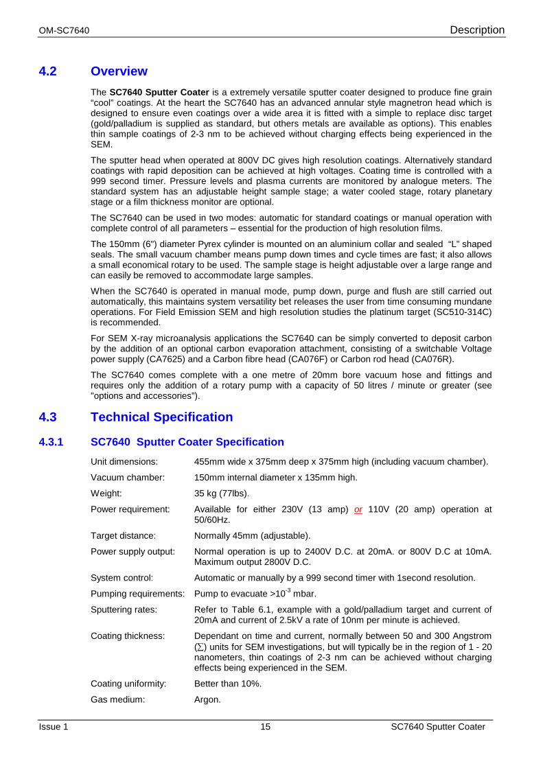
The SC7640 operates at a potential of up to 3000 Volts dc.
An HV voltage is applied between the Target (cathode) and Baseplate (anode) which is at earth potential. A pressure interlock ensures that the HV supply cannot be activated until vacuum chamber pressure is reduced to 10-1 mbar or better. Low pressure gas (argon is preferred) is leaked into the vacuum chamber to provide a medium for ionisation. Figure 4.2 shows the principles of operation of the SC7640.
Electrons emitted by the cathode, concentrated in the vicinity of the target by the magnetic field, collide with the gas molecules, producing positive ions (due to secondary electron emission). Positive ions attracted by the negative potential of the cathode, bombard the target, causing erosion of the target material. The dislodged target atoms falling toward the sample follow multiple paths due to collisions with the ionized gas, coating the sample on all exposed faces.
A gas discharge glow centered about the cathode is visible.
Figure 4.2 Sputter Coater Operation
4.4.2 Pumping Requirements The work chamber has to be evacuated to <2 x 10⁻² mbar. This can be achieved in a reasonable time (depending on the cleanliness of the chamber) using a 90 l/m two stage rotary pump, preferably incorporating an anti-suck back device and fitted with an oil mist filter on the exhaust.
4.5 Interlocks Safety interlocks are incorporated in the SC7640 Sputter Coater to prevent high voltage power being switched on with the chamber top plate not in the closed position. A vacuum switch will also disable the high voltage power should the pressure rise beyond operating parameters.
WARNING HAZARD TO HEALTH!
Potentially lethal voltages are used in this equipment. Under no circumstances should interlock connections be over-ridden.
Description OM-SC7640
SC7640 Sputter Coater 18 Issue 1
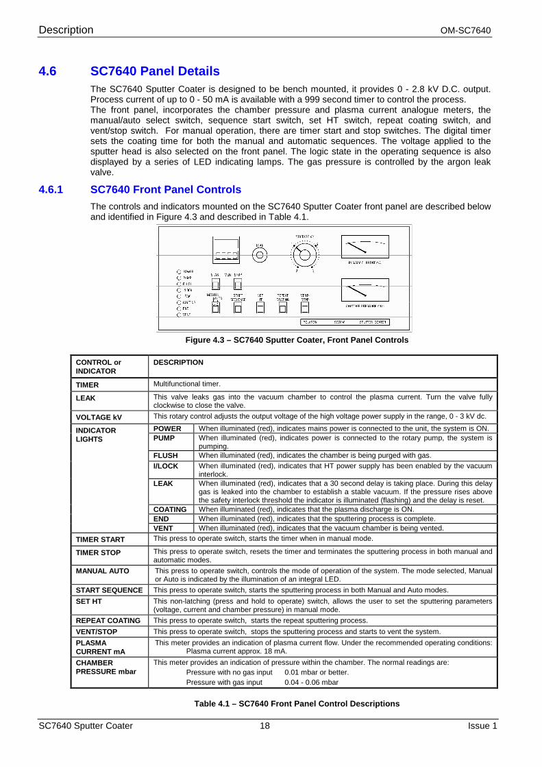
4.6 SC7640 Panel Details The SC7640 Sputter Coater is designed to be bench mounted, it provides 0 - 2.8 kV D.C. output. Process current of up to 0 - 50 mA is available with a 999 second timer to control the process. The front panel, incorporates the chamber pressure and plasma current analogue meters, the manual/auto select switch, sequence start switch, set HT switch, repeat coating switch, and vent/stop switch. For manual operation, there are timer start and stop switches. The digital timer sets the coating time for both the manual and automatic sequences. The voltage applied to the sputter head is also selected on the front panel. The logic state in the operating sequence is also displayed by a series of LED indicating lamps. The gas pressure is controlled by the argon leak valve.
4.6.1 SC7640 Front Panel Controls The controls and indicators mounted on the SC7640 Sputter Coater front panel are described below and identified in Figure 4.3 and described in Table 4.1.
Figure 4.3 – SC7640 Sputter Coater, Front Panel Controls
CONTROL or INDICATOR
DESCRIPTION
TIMER Multifunctional timer.
LEAK This valve leaks gas into the vacuum chamber to control the plasma current. Turn the valve fully clockwise to close the valve.
VOLTAGE kV This rotary control adjusts the output voltage of the high voltage power supply in the range, 0 - 3 kV dc.
POWER When illuminated (red), indicates mains power is connected to the unit, the system is ON. PUMP When illuminated (red), indicates power is connected to the rotary pump, the system is
pumping. FLUSH When illuminated (red), indicates the chamber is being purged with gas. I/LOCK When illuminated (red), indicates that HT power supply has been enabled by the vacuum
interlock. LEAK When illuminated (red), indicates that a 30 second delay is taking place. During this delay
gas is leaked into the chamber to establish a stable vacuum. If the pressure rises above the safety interlock threshold the indicator is illuminated (flashing) and the delay is reset.
COATING When illuminated (red), indicates that the plasma discharge is ON. END When illuminated (red), indicates that the sputtering process is complete.
INDICATOR LIGHTS
VENT When illuminated (red), indicates that the vacuum chamber is being vented. TIMER START This press to operate switch, starts the timer when in manual mode.
TIMER STOP This press to operate switch, resets the timer and terminates the sputtering process in both manual and automatic modes.
MANUAL AUTO This press to operate switch, controls the mode of operation of the system. The mode selected, Manual or Auto is indicated by the illumination of an integral LED.
START SEQUENCE This press to operate switch, starts the sputtering process in both Manual and Auto modes. SET HT This non-latching (press and hold to operate) switch, allows the user to set the sputtering parameters
(voltage, current and chamber pressure) in manual mode. REPEAT COATING This press to operate switch, starts the repeat sputtering process. VENT/STOP This press to operate switch, stops the sputtering process and starts to vent the system. PLASMA CURRENT mA
This meter provides an indication of plasma current flow. Under the recommended operating conditions: Plasma current approx. 18 mA.
CHAMBER PRESSURE mbar
This meter provides an indication of pressure within the chamber. The normal readings are: Pressure with no gas input 0.01 mbar or better. Pressure with gas input 0.04 - 0.06 mbar
Table 4.1 – SC7640 Front Panel Control Descriptions
OM-SC7640 Description
Issue 1 19 SC7640 Sputter Coater
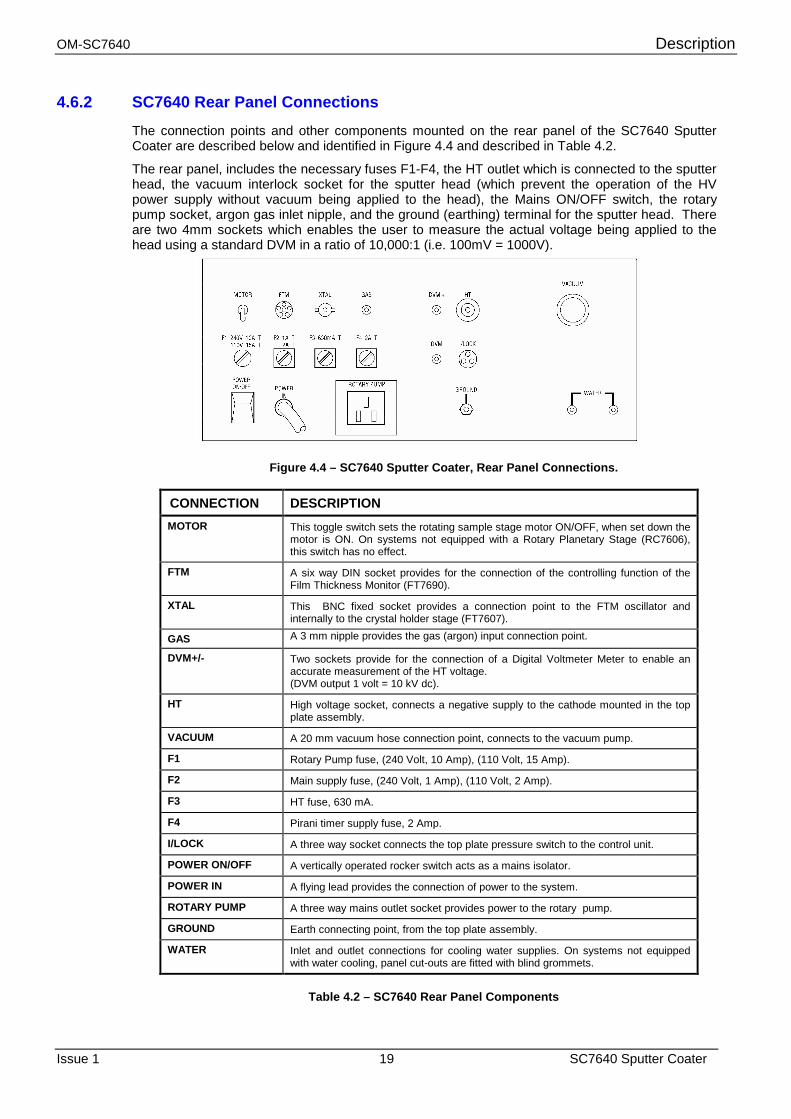
4.6.2 SC7640 Rear Panel Connections
The connection points and other components mounted on the rear panel of the SC7640 Sputter Coater are described below and identified in Figure 4.4 and described in Table 4.2.
The rear panel, includes the necessary fuses F1-F4, the HT outlet which is connected to the sputter head, the vacuum interlock socket for the sputter head (which prevent the operation of the HV power supply without vacuum being applied to the head), the Mains ON/OFF switch, the rotary pump socket, argon gas inlet nipple, and the ground (earthing) terminal for the sputter head. There are two 4mm sockets which enables the user to measure the actual voltage being applied to the head using a standard DVM in a ratio of 10,000:1 (i.e. 100mV = 1000V).
Figure 4.4 – SC7640 Sputter Coater, Rear Panel Connections.
CONNECTION DESCRIPTION MOTOR This toggle switch sets the rotating sample stage motor ON/OFF, when set down the
motor is ON. On systems not equipped with a Rotary Planetary Stage (RC7606), this switch has no effect.
FTM A six way DIN socket provides for the connection of the controlling function of the Film Thickness Monitor (FT7690).
XTAL This BNC fixed socket provides a connection point to the FTM oscillator and internally to the crystal holder stage (FT7607).
GAS A 3 mm nipple provides the gas (argon) input connection point.
DVM+/- Two sockets provide for the connection of a Digital Voltmeter Meter to enable an accurate measurement of the HT voltage. (DVM output 1 volt = 10 kV dc).
HT High voltage socket, connects a negative supply to the cathode mounted in the top plate assembly.
VACUUM A 20 mm vacuum hose connection point, connects to the vacuum pump.
F1 Rotary Pump fuse, (240 Volt, 10 Amp), (110 Volt, 15 Amp).
F2 Main supply fuse, (240 Volt, 1 Amp), (110 Volt, 2 Amp).
F3 HT fuse, 630 mA.
F4 Pirani timer supply fuse, 2 Amp.
I/LOCK A three way socket connects the top plate pressure switch to the control unit.
POWER ON/OFF A vertically operated rocker switch acts as a mains isolator.
POWER IN A flying lead provides the connection of power to the system.
ROTARY PUMP A three way mains outlet socket provides power to the rotary pump.
GROUND Earth connecting point, from the top plate assembly.
WATER Inlet and outlet connections for cooling water supplies. On systems not equipped with water cooling, panel cut-outs are fitted with blind grommets.
Table 4.2 – SC7640 Rear Panel Components
Installation OM-SC7640
SC7640 Sputter Coater 20 Issue 1
5 Installation Quorum Technologies has carefully packed the SC7640 Sputter Coater instrument so that it will reach its destination in perfect operating order. Do NOT discard any packing materials until the unit has been inspected for any transit damage and the instrument has been used to the customers satisfaction.
If any damage is found, notify the carrier and Quorum Technologies (or local agent) immediately. If it is necessary to return the shipment, use the packaging as supplied and follow the instructions in this manual for return of goods paragraph 3.1.
5.1 Unpacking Checklist The Equipment package will normally be despatched from the factory in one box. Inside the box the following will be found, refer and check each item off against the supplied packing list.
◆◆◆◆ SC7640 Sputter Coater - packed in its own internal packaging. (Target fitted to the Top Plate).
◆◆◆◆ SC7640 Glass Cylinder – packed separately.
◆◆◆◆ SC7640 START-UP kit - packed in a polythene bag.
◆ Optional Spares - packed individually.
◆ Documentation - Inserted in a folder, containing the operating manual and a standard forms pack.
5.1.1 Preparation (a) Ensure that a suitable mains electricity supply (110 Vac - 20amps or 240 Vac - 13amps,
frequency 50/60 Hz) is available. Check that the voltage label attached to the side of the cabinet is suitable for the local voltage and frequency.
The units are supplied for either 230V or 110V operation at 50/60Hz. The power rating is 250VA excluding the rotary pump. The rotary pump outlet is rated at 230V 10A or 110V at 16A. The 240V pump outlet uses a 3-pin plug (404440310) which is supplied or 110V standard US plug (not supplied).
(b) Ensure that a suitable gas supply is available.
Typically: A commerical cylinder of Argon Gas (Zero Grade), fitted with a two stage regulator, in order to deliver gas at a pressure around 5-10 psi (0.7bar).
(c) Ensure that a suitable cooling water supply is available.
This service is not required, unless the water-cooled stage option is fitted.
Ensure that a suitable supply of cooling water is available, a flow rate of 1 - 3 litres / minute of clean water is required. If a closed circuit recirculating chiller is used, avoid operating below dew point.
(d) Ensure that a suitable vacuum pump is available.
Where a rotary pump is used, ensure that the rotary pump has been filled with oil, in accordance with the manufacturers instructions. The exhaust should be filtered or expelled to a safe area. All pumps supplied by Quorum Technologies are fitted with an exhaust filter.
OM-SC7640 Installation
Issue 1 21 SC7640 Sputter Coater
5.2 SC7640 Installation
WARNING HAZARD TO HEALTH!
Potentially lethal voltages are used in this equipment. Before making / breaking connections to the equipment, ensure
power is switched off and that it is safe to proceed.
WARNING HAZARD TO HEALTH!
Precautions to be taken when lifting this equipment. Weight of unit is 35 Kilograms (77lbs)
(a) Position the Sputter Coater Cabinet on a suitable level working surface, Access to both front
and rear of the cabinet are required.
(b) Clean the ‘L’ section gaskets using a cloth moistened with isopropanol Fit to the glass cylinder, then position the cylinder centrally on the base plate (mounted on top of the cabinet).
(c) Position the top plate assembly on the glass cylinder.
(d) Position the vacuum pump as close as possible to the Sputter Coater.
5.2.1 Connections
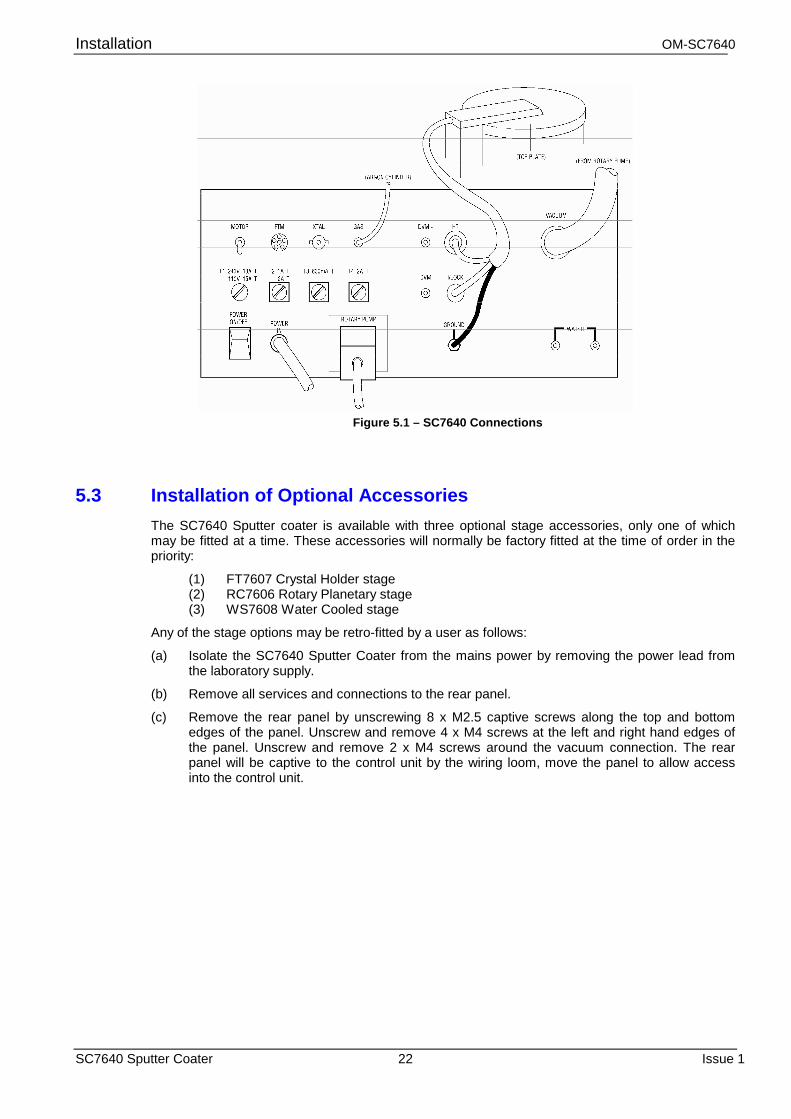
The connections to be made are described below and illustrated in figure 5.1.
(a) Make the following hose connections to the rear panel of the cabinet:
(i) Connect from argon cylinder regulator to GAS hose nipple.
(ii) Connect the rotary pump to the (VACUUM) connector using 20 mm bore vacuum tubing, secure using hose clips or tie-wraps. Ensure the minimum length of hose is used.
(iii) If the system is fitted with water cooling make connections to the WATER hose nipples using 6 mm bore tubing.
(b) Connect the Top Plate assembly to the rear panel of the cabinet using the attached connectors:
(i) Connect the HT cable, to the HT socket on rear panel.
(ii) Connect the 3-way connector to the I/LOCK connector on the rear panel.
(c) Make the following electrical connections to the rear panel of the cabinet:
(i) Connect (ROTARY PUMP) power out to the vacuum pump. If a rotary pump is supplied with the Sputter Coater a suitable connecting cable is supplied with the pump, otherwise a suitable 3-way plug (which can be wired by the user) is supplied.
(ii) Connect the mains (POWER IN) cable via a suitable plug to the local supply, in accordance with the cable colour coding:
Brown - Live Blue - Neutral Green/Yellow - Earth
Installation OM-SC7640
SC7640 Sputter Coater 22 Issue 1
Figure 5.1 – SC7640 Connections
5.3 Installation of Optional Accessories The SC7640 Sputter coater is available with three optional stage accessories, only one of which may be fitted at a time. These accessories will normally be factory fitted at the time of order in the priority:
(1) FT7607 Crystal Holder stage (2) RC7606 Rotary Planetary stage (3) WS7608 Water Cooled stage
Any of the stage options may be retro-fitted by a user as follows:
(a) Isolate the SC7640 Sputter Coater from the mains power by removing the power lead from the laboratory supply.
(b) Remove all services and connections to the rear panel.
(c) Remove the rear panel by unscrewing 8 x M2.5 captive screws along the top and bottom edges of the panel. Unscrew and remove 4 x M4 screws at the left and right hand edges of the panel. Unscrew and remove 2 x M4 screws around the vacuum connection. The rear panel will be captive to the control unit by the wiring loom, move the panel to allow access into the control unit.
OM-SC7640 Installation
Issue 1 23 SC7640 Sputter Coater
5.3.1 FT7607 Crystal Holder Stage
(a) Remove the standard adjustable height stage from the base plate by unscrewing and removing 3 x M4 cap head screws. The stage may now be lifted from the base plate, a compressed ‘O’ ring in the stage flange provides the vacuum seal.
(b) Insert the FT7607 Crystal Holder Stage into the base plate ensuring the ‘O’ ring seal is clean and lightly greased. Retain the FT7607 stage to the base plate using the 3 x M4 screws provided. Connect the supplied BNC-BNC cable between the stage fitting and the rear panel XTAL fitting.
(c) Re-fit the rear panel and connect all the removed services. The FT7690 Film Thickness Monitor will be required to complete the installation. The FT7690 is fitted external to the SC7640 Sputter Coater and is connected to the FTM socket and a suitable mains supply.
5.3.2 RC7606 Rotary Planetary Stage
(a) Remove the standard adjustable height stage from the base plate by unscrewing and removing 3 x M4 cap head screws. The stage may now be lifted from the base plate, a compressed ‘O’ ring in the stage flange provides the vacuum seal.
(b) Insert the RC7606 Rotary Planetary Stage into the base plate ensuring the ‘O’ ring seal is clean and lightly greased. Retain the RC7606 stage to the base plate using the 3 x M4 screws provided. (c) Connect the flying lead from the RC7606 motor to the coiled flying lead located on the control unit chassis below the base plate.
(c) Re-fit the rear panel and connect all the removed services. On/off control of the RC7606 stage is provided by the MOTOR switch located on the rear panel.
5.3.3 WS7608 Water Cooled Stage:
(a) Remove the standard adjustable height stage from the base plate by unscrewing and removing 3 x M4 cap head screws. The stage may now be lifted from the base plate, a compression ‘O’ ring in the stage flange provides the vacuum seal.
(b) Insert the WS7608 Water Cooled stage into the base plate ensuring the ‘O’ ring seal is clean and lightly greased. Retain the WS7608 stage to the base plate using the 3 x M4 screws provided. Remove 2 x blanking covers located on the rear panel ‘WATER’ legend. Insert the two water fittings into the exposed holes and retain with the nuts provided.
(c) Prior to re-fitting the rear panel and services, test the liquid path of the stage to ensure there are no leaks by connecting the water fittings to a water supply.
(d) Re-fit the rear panel and connect all the removed services.
Operation OM-SC7640
SC7640 Sputter Coater 24 Issue 1
6 Operation The SC7640 Sputter Coater is designed to be durable and has a long lifetime. The instrument does contain items, primarily the Target that has finite lifetimes, in order to sustain optimum performance it will need replacing periodically. The lifespan of the Target is dependent on a number of factors, including operating in good vacuum levels, contamination and the purity of the gas being used. The Target should be replaced when it starts to become perforated.
6.1 Test Procedure
CAUTION Contamination can seriously affect the sputtering process
To reduce the possibility of contamination by airborne particles, minimise the time the vacuum chamber is open to the atmosphere.
This test procedure, which checks the system is operating correctly, should be performed at the following times:
After the installation process has been completed.
After any operation that could lead to contamination of the vacuum chamber.
(a) Preparation
(i) Check that LEAK valve is closed, (fully clockwise) do not over-tighten.
(ii) Check the argon cylinder regulator is open. Set pressure to 0.7 bar (5-10psi).
(iii) Check that mains power is available, set the rear panel mounted POWER ON/OFF switch to the down position (ON). The POWER indicator and MANUAL / AUTO switch indicator will indicate AUTO.
(b) Set vacuum pressure. (i) Operate MANUAL / AUTO button, the MANUAL indicator will illuminate.
(ii) Set TIME control to 10 seconds.
(iii) Set VOLTAGE control to 0 volts (fully counter-clockwise).
(iv) Press the START SEQUENCE button, The rotary pump will start (the PUMP indicator will illuminate), the CHAMBER PRESSURE meter will indicate a falling pressure. When pressure falls to 10-1 mbar (approx.), the flush valve will open (the FLUSH indicator will illuminate) for 5 seconds, purging the system with process gas. The system will continue to pump down. When the pressure falls below < 10-1 mbar the I/LOCK indicator will illuminate. Wait until the system reaches ultimate pressure, typically <1 x 10⁻² mbar.
OM-SC7640 Operation
Issue 1 25 SC7640 Sputter Coater
(c) Set process current
(i) Set the VOLTAGE control to 2.2 kV.
(ii) Press and hold the SET HT button, no current should be indicated on the PLASMA CURRENT meter. If current is indicated (a plasma discharge will be seen in the vacuum chamber), release SET HT button, wait for system to pump down further.
(iii) With the SET HT button held and no current indicated, open the LEAK valve until the chamber pressure begins to rise. Whilst monitoring the PLASMA CURRENT meter, adjust the LEAK valve for a current of 10 - 20 mA, (a strong plasma discharge will be seen in the chamber). Release the SET HT button, the plasma discharge will extinguish.
(d) Timer operation
(i) Operate the timer START button, the plasma will strike and the sputtering process will deposit target material on the base plate. The COATING indicator will illuminate (flashing).
(ii) After 10 seconds the plasma discharge will terminate, the COATING indicator will cease flashing and the END indicator will illuminate.
(iii) The rotary vacuum pump will continue to operate maintaining the chamber pressure at the level set by the LEAK valve.
(e) Vent system to process gas.
(i) Press and hold the VENT/STOP button. The VENT indicator will illuminate, the rotary vacuum pump will stop and the chamber will be vented to process gas (argon). All the indicators except POWER and VENT will be extinguished.
(ii) When sufficient gas has entered the vacuum chamber, positive pressure will ‘pop’ the vacuum chamber open (typically, after 30 seconds). To close the vent valve, release the VENT button.
(iii) Do not disturb the VOLTAGE and LEAK control settings.
(f) Automatic mode of operation
The automatic mode of operation relies on the settings of VOLTAGE and LEAK controls set in the manual mode (as above)
(i) Operate the MANUAL /AUTO button the integral AUTO indicator will illuminate.
(ii) Operate the START SEQUENCE button. An automatic sputtering process will be completed (as tested in the manual mode above), the indicators will mimic the sequence of operations.
(iii) When the sputtering process is complete, (END indicator illuminated), vent the system to process gas, see (e) above.
(g) System shut down.
After completion of a work schedule, close down as follows:
(i) Close the LEAK valve (turn fully clockwise).
(ii) Turn POWER (rear panel of 7640) to OFF, all indicators will extinguish.
(iii) Turn OFF process gas cylinder.
Operation OM-SC7640
SC7640 Sputter Coater 26 Issue 1
6.2 Coating Process A metal film of uniform thickness between 50 and 300 Å is generally used for SEM investigations.
Care must be taken to ensure the vacuum chamber is kept clean and free from contamination. Contamination which can arise from the out-gassing of specimens, adhesives (especially Chlorohydrocarbon based solvents) and rubber gaskets will adversely affect the quality and rate of sputtering.
A measure of thickness can be obtained using the following equation: d = KIVt
d The coating thickness in Angstrom units.
K An experimentally determined constant based on: The metal being sputtered, The gas being used, 45 mm (approx.) target to sample distance. For gold used with argon, K = 0.17 approx. For gold used with air, K = 0.07 approx.
I is plasma current, in mA.
V is the applied voltage, in kV, (1 kV).
t is the sputtering time, in seconds.
For a typical sputtering, using gold in argon with a plasma current of 18 mA for 120 seconds:
d = KIVt = 0.17 x 18 x 1 x 120
= 367 Å (approx. 3 Å / second)
The uniformity of the coating thickness within the area of the specimen holder is better than 10%.
6.3 Coating Specimens
6.3.1 Coating in Manual Mode – High Resolution
(a) Mount specimens (i) Prepare specimens on stubs, using an approved method. (ii) Raise the vacuum chamber Top Plate. (iii) If necessary adjust the height of the sample stage. Whilst the most suitable
height for a particular application can best be established empirically, 50mm between top of the sample and the target provides a satisfactory general purpose setting. Access to the sample stage can be improved by lifting the glass cylinder clear of the system.
(iv) Mount the stubs (with attached samples) on the sample stage. (v) Lower the hinged top plate to close the vacuum chamber, ensure the surfaces
are clean. (b) Preparation
(i) This procedure assumes that the test procedure (4.1) has been completed and that the LEAK valve and VOLTAGE controls have been set.
(ii) Check the process gas (argon) cylinder regulator is open. Set pressure to 0.7 bar (5psi).
(iii) Check that mains power is available, set the rear panel mounted POWER ON/OFF switch to the down position (ON). The POWER indicator and MANUAL / AUTO switch indicator will indicate AUTO.
OM-SC7640 Operation
Issue 1 27 SC7640 Sputter Coater
(c) Set vacuum pressure (i) Operate MANUAL / AUTO button, the MANUAL indicator will illuminate.
(ii) Press the START SEQUENCE button, The rotary pump will start (the PUMP indicator will illuminate), the CHAMBER PRESSURE meter will indicate a falling pressure. When pressure falls to 10-1 mbar (approx.), the flush valve will open (the FLUSH indicator will illuminate) for 5 seconds, purging the system with process gas. The system will continue to pump down until the lowest pressure is reached. (If the leak valve is closed the system will reach its lowest pressure, typically <2 x 10⁻² mbar. Open leak valve and allow pressure to rise to 10-1 mbar. Close leak valve and allow system to reach ultimate pressure.
(d) Set process current
(i) Set the VOLTAGE control to 800V.
(ii) Press and hold the SET HT button, the solenoid operated section of the LEAK valve will open allowing system gas to enter the vacuum chamber. Whilst monitoring the PLASMA CURRENT meter, adjust the LEAK valve for an indicated current of about 5-10 mA, a plasma discharge will just be seen in the chamber. Release the SET HT button, the plasma discharge will extinguish.
(e) Sputter coating
(i) Set TIMER control to required duration (typically 60 seconds).
(ii) Operate the START button. The sputtering process will run for the duration of timer setting, whilst the timer is running the COATING indicator will be illuminated flashing. The process can be terminated by pressing the STOP button. During the coating process it may be necessary to adjust the leak valve to maintain the 5-10 mA plasma current.
(iii) The process can be repeated by operating either REPEAT COATING or by pressing the START button again.
(iv) On completion of the sputtering process, the plasma discharge will extinguish and the END indicator will illuminate.
(f) Vent system to process gas.
(i) Press and hold the VENT/STOP button. The VENT indicator will illuminate, the rotary vacuum pump will stop and the chamber will be vented to process gas (argon). All the indicators except POWER and VENT will be extinguished.
(ii) When sufficient gas has entered the vacuum chamber, positive pressure will ‘pop’ the vacuum chamber open. Release the VENT/STOP button, the vent valve will close and the VENT indicator will extinguish.
(iii) Do not disturb the VOLTAGE and LEAK control settings.
(g) Remove Specimens
(i) Raise the Top Plate to open the vacuum chamber. Remove the coated samples.
(ii) If the system is not to be reused immediately, lower the Top Plate to protect the vacuum chamber against air borne contaminants.
Operation OM-SC7640
SC7640 Sputter Coater 28 Issue 1
6.3.2 Coating in Manual Mode - Routine
(a) Mount specimens (i) Prepare specimens on stubs, using an approved method. (ii) Raise the vacuum chamber Top Plate. (iii) If necessary adjust the height of the sample stage. Whilst the most suitable height for
a particular application can best be established empirically, 50mm between top of the sample and the target provides a satisfactory general purpose setting. Access to the sample stage can be improved by lifting the glass cylinder clear of the system.
(iv) Mount the stubs (with attached samples) on the sample stage. (v) Lower the hinged top plate to close the vacuum chamber, ensure the surfaces are
clean. (b) Preparation
(i) This procedure assumes that the test procedure (4.1) has been completed and that the LEAK valve and VOLTAGE controls have been set.
(ii) Check the process gas (argon) cylinder regulator is open. Set pressure to 0.7 bar (5psi).
(iii) Check that mains power is available, set the rear panel mounted POWER ON/OFF switch to the down position (ON). The POWER indicator and MANUAL / AUTO switch indicator will indicate AUTO.
(c) Set vacuum pressure
(i) Operate MANUAL / AUTO button, the MANUAL indicator will illuminate.
(ii) Press the START SEQUENCE button, The rotary pump will start (the PUMP indicator will illuminate), the CHAMBER PRESSURE meter will indicate a falling pressure. When pressure falls to 10-1 mbar (approx.), the flush valve will open (the FLUSH indicator will illuminate) for 5 seconds, purging the system with process gas. The system will continue to pump down until the lowest pressure is reached.
(If the leak valve is closed the system will reach its lowest pressure, typically <2 x 10⁻² mbar.
(d) Set process current
(i) Set the VOLTAGE control to 2.2 kV.
(ii) Press and hold the SET HT button, the solenoid operated section of the LEAK valve will open allowing system gas to enter the vacuum chamber. Whilst monitoring the PLASMA CURRENT meter, adjust the LEAK valve for an indicated current of about 20 mA, a plasma discharge will be seen in the chamber. Release the SET HT button, the plasma discharge will extinguish.
(e) Sputter coating
(i) Set TIMER control to required duration (typically 60 seconds).
(ii) Operate the START button. The sputtering process will run for the duration of timer setting, whilst the timer is running the COATING indicator will be illuminated flashing. The process can be terminated by pressing the STOP button.
(iii) The process can be repeated by operating either REPEAT COATING or by pressing the START button again.
(iv) On completion of the sputtering process, the plasma discharge will extinguish and the END indicator will illuminate.
OM-SC7640 Operation
Issue 1 29 SC7640 Sputter Coater
(f) Vent system to process gas.
(i) Press and hold the VENT/STOP button. The VENT indicator will illuminate, the rotary vacuum pump will stop and the chamber will be vented to process gas (argon). All the indicators except POWER and VENT will be extinguished.
(ii) When sufficient gas has entered the vacuum chamber, positive pressure will ‘pop’ the vacuum chamber open. Release the VENT/STOP button, the vent valve will close and the VENT indicator will extinguish.
(iii) Do not disturb the VOLTAGE and LEAK control settings.
(g) Remove Specimens
(i) Raise the Top Plate to open the vacuum chamber. Remove the coated samples.
(ii) If the system is not to be reused immediately, lower the Top Plate to protect the vacuum chamber against air borne contaminants.
6.3.3 Coating in Automatic Mode
When operating in automatic mode, satisfactory coating will only be achieved if the front panel controls, LEAK valve and VOLTAGE , are correctly set in manual mode (see above). It is essential that prior to operation in the automatic mode, a single manual process is completed, to ascertain suitable settings for LEAK and VOLTAGE controls.
(a) Mount specimens.
(i) Prepare specimens on stubs, using an approved method.
(ii) Raise the vacuum chamber Top Plate.
(iii) Mount the stubs (with attached samples) on the sample stage.
(iv) Lower the hinged top plate to close the vacuum chamber, ensure the surfaces are clean.
(b) Automatic Sputter Coating
(i) Operate the MANUAL /AUTO button the integral AUTO indicator will illuminate.
(ii) Set the TIMER to the required duration, (typically 60 seconds).
(iii) Operate the START SEQUENCE button. An automatic sputtering process will be run, the indicators will mimic the sequence of operations. When the sputtering process has been completed the END indicator will illuminate.
(iv) If a thicker coating is required, operate the REPEAT COATING button, (the timer can be reset if required).
(c) Recover Specimens
(i) Press and hold the VENT/STOP button. The VENT indicator will illuminate, the rotary vacuum pump will stop and the chamber will be vented to process gas (argon). All the indicators except POWER and VENT will be extinguished.
(ii) When sufficient gas has entered the vacuum chamber, positive pressure will ‘pop’ the vacuum chamber open. Release the VENT/STOP button, the vent valve will close and the VENT indicator will extinguish.
(iii) Raise the Top Plate to open the vacuum chamber. Remove the coated samples.
(iv) If the system is not to be reused immediately, lower the Top Plate to protect the vacuum chamber against airborne contaminants.
Operation OM-SC7640
SC7640 Sputter Coater 30 Issue 1
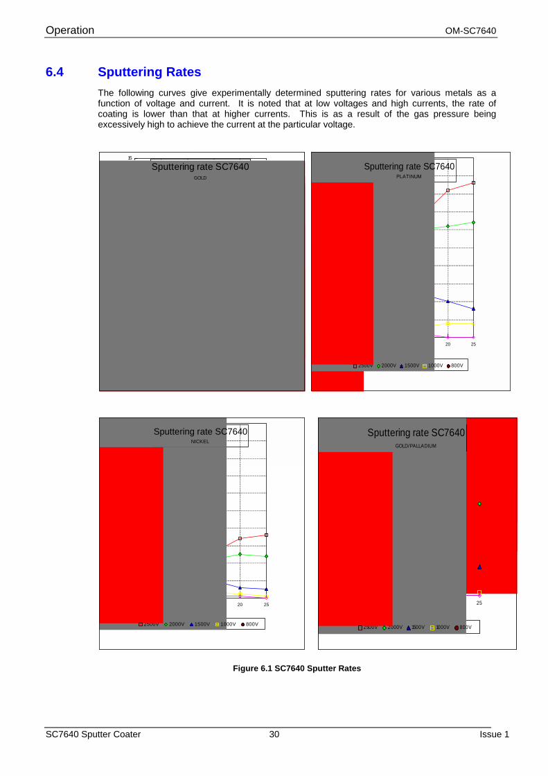
6.4 Sputtering Rates The following curves give experimentally determined sputtering rates for various metals as a function of voltage and current. It is noted that at low voltages and high currents, the rate of coating is lower than that at higher currents. This is as a result of the gas pressure being excessively high to achieve the current at the particular voltage.
Figure 6.1 SC7640 Sputter Rates
0 5 10 15 20 250
5
10
15
Plasma Current (mA)
Rat
e (n
m/m
in)
2500V 2000V 1500V 1000V 800V
Sputtering rate SC7640GOLD
0 5 10 15 20 250
1
2
3
4
5
6
7
8
9
10
Plasma Current (mA)
Rat
e (n
m/m
in)
2500V 2000V 1500V 1000V 800V
Sputtering rate SC7640PLATINUM
0 5 10 15 20 250
1
2
3
4
5
6
7
8
9
10
Plasma Current (mA)
Rat
e (n
m/m
in)
2500V 2000V 1500V 1000V 800V
Sputtering rate SC7640NICKEL
0 5 10 15 20 250
5
10
15
Plasma Current (mA)
Rat
e (n
m/m
in)
2500V 2000V 1500V 1000V 800V
Sputtering rate SC7640GOLD/PALLADIUM
OM-SC7640 Maintenance
Issue 1 31 SC7640 Sputter Coater
7 Maintenance For technical and applications advice plus our on-line shop for spares and consumable parts visit www.quorumtech.com
7.1 Maintenance - General
WARNING HAZARD TO HEALTH!
Potentially lethal voltages are used in this equipment. Before making / breaking connections to the equipment, ensure power
is switched off on the the Electronics unit.
(a) The procedures listed in this chapter should only be done by persons who have had training and who have achieved a satisfactory knowledge of the necessary skills and techniques.
(b) If repairs entail the dismantling of any part of the vacuum system, care must be taken to ensure that it is not contaminated (by dust or fingerprints).
(i) Always wear disposable plastic gloves. (ii) Do NOT handle internal surfaces. (iii) Whenever possible, cover to protect against dust.
7.2 Cleaning Use a damp cloth or proprietary equipment cleaner to remove surface grime from the outer
surfaces of the cabinet and vacuum chamber. Finish with a dry lint free cloth to remove smearing.
7.2.1 Vacuum Chamber Cleaning
Cleaning of the vacuum chamber is required if the interior of the chamber becomes contaminated, cleaning on a regular basis is unnecessary. The fact that the glass walls of the chamber becomes coated with target material and the sample cannot be seen, should not normally be considered reason to clean the system.
If the system is contaminated by handling or air-bourne pollution, carry out the following procedure.
For cleaning use a nylon abrasive pad (Scotchbrite or similar) and Cleaning fluid (Isopropanol or menthyl alchol). (a) Ensure power, water and gas supplies to the sputter coater are set to OFF. (b) Remove all electrical, gas, water and vacuum connections from the rear of the instrument.
Move the sputter coater to a clean working area. (c) Raise the top plate to expose the target. Disassemble the glass cylinder and ‘L’ gaskets from
the cabinet assembly. (d) Lightly abrade all the accessible interior surfaces of the vacuum chamber to remove any
deposits (not the target) and the glass cylinder, to remove any deposits. Finish with a lint free tissue moistened with isopropanol. Cover cleaned components to prevent further contamination.
(e) The target is self cleaning in use and should not require attention. If the target is damaged, replace the target, see section 7.3.
(f) The vacuum and gas tubing cannot be readily cleaned, if these items are suspect or showing signs of ageing they should be replaced.
(g) Reassemble the vacuum chamber components. (h) Reconnect the electrical and gas tubing connections from the Top Plate assembly at the rear
of the cabinet. (i) Return the sputter coater to its working position. Reconnect the electrical, vacuum, gas and
water connectors to the cabinet rear panel. (j) When taking the system back into service carry out the Test Procedure (see chapter 6.1),
this will ensure the system is thoroughly dried out.
Maintenance OM-SC7640
SC7640 Sputter Coater 32 Issue 1
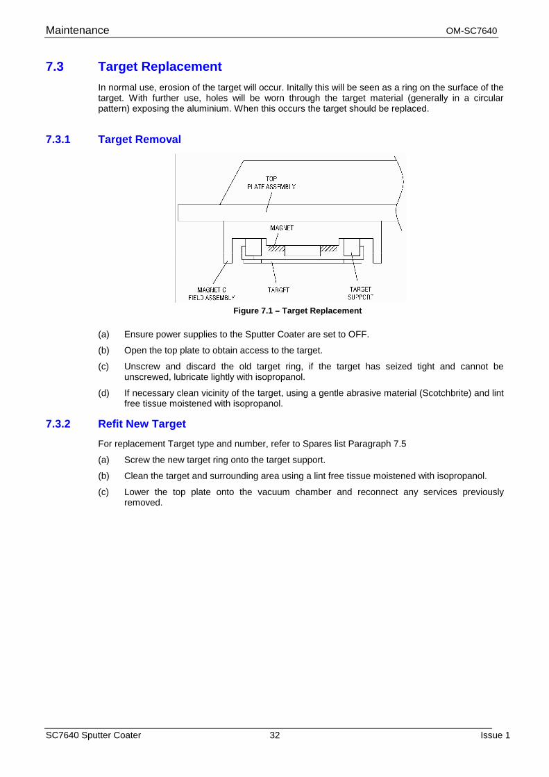
7.3 Target Replacement In normal use, erosion of the target will occur. Initally this will be seen as a ring on the surface of the target. With further use, holes will be worn through the target material (generally in a circular pattern) exposing the aluminium. When this occurs the target should be replaced.
7.3.1 Target Removal
Figure 7.1 – Target Replacement
(a) Ensure power supplies to the Sputter Coater are set to OFF.
(b) Open the top plate to obtain access to the target.
(c) Unscrew and discard the old target ring, if the target has seized tight and cannot be unscrewed, lubricate lightly with isopropanol.
(d) If necessary clean vicinity of the target, using a gentle abrasive material (Scotchbrite) and lint free tissue moistened with isopropanol.
7.3.2 Refit New Target
For replacement Target type and number, refer to Spares list Paragraph 7.5
(a) Screw the new target ring onto the target support.
(b) Clean the target and surrounding area using a lint free tissue moistened with isopropanol.
(c) Lower the top plate onto the vacuum chamber and reconnect any services previously removed.
OM-SC7640 Maintenance
Issue 1 33 SC7640 Sputter Coater
7.4 No Plasma Current If when SET HT is operated and the VOLTAGE control is turned clockwise there is no indication on the PLASMA CURRENT meter, check the following:
(a) If I/LOCK indicator is not illuminated, check the vacuum pressure. Until the vacuum pressure has reduced to 10-1 mbar, the interlock will inhibit the HT.
(b) If I/LOCK indicator is illuminated, check fuse F3 (HT fuse, fitted to Sputter Coater rear panel). If fuse is blown replace with the correct fuse F3, 630mA anti-surge (405020230).
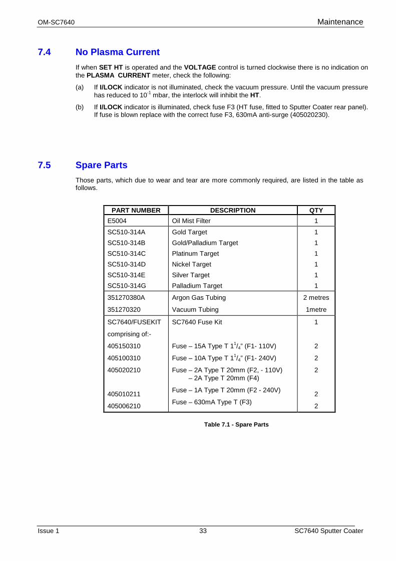
7.5 Spare Parts Those parts, which due to wear and tear are more commonly required, are listed in the table as follows.
PART NUMBER DESCRIPTION QTY
E5004 Oil Mist Filter 1
SC510-314A SC510-314B SC510-314C SC510-314D SC510-314E SC510-314G
Gold Target Gold/Palladium Target Platinum Target Nickel Target Silver Target Palladium Target
1 1 1 1 1 1
351270380A
351270320
Argon Gas Tubing
Vacuum Tubing
2 metres
1metre
SC7640/FUSEKIT
comprising of:-
405150310
405100310
405020210
405010211
405006210
SC7640 Fuse Kit
Fuse – 15A Type T 11/4” (F1- 110V)
Fuse – 10A Type T 11/4” (F1- 240V)
Fuse – 2A Type T 20mm (F2, - 110V) – 2A Type T 20mm (F4)
Fuse – 1A Type T 20mm (F2 - 240V)
Fuse – 630mA Type T (F3)
1
2
2
2
2
2
Table 7.1 - Spare Parts
Fault Finding OM-SC7640
SC7640 Sputter Coater 34 Issue 1
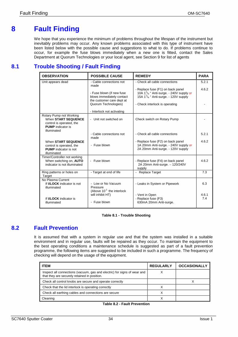
8 Fault Finding We hope that you experience the minimum of problems throughout the lifespan of the instrument but inevitably problems may occur. Any known problems associated with this type of instrument have been listed below with the possible cause and suggestions to what to do. If problems continue to occur, for example the fuse blows immediately when a new one is fitted, contact the Sales Department at Quorum Technologies or your local agent, see Section 9 for list of agents
8.1 Trouble Shooting / Fault Finding OBSERVATION POSSIBLE CAUSE REMEDY PARA Unit appears dead - Cable connections not
made - Fuse blown (if new fuse blows immediately contact the customer care dept at Quorum Technologies) - Interlock not activating
- Check all cable connections - Replace fuse (F1) on back panel 10A 11/4 “ Anti-surge. - 240V supply or 15A 11/4 “ Anti-surge. - 120V supply - Check interlock is operating
5.2.1
4.6.2 -
Rotary Pump not Working When START SEQUENCE control is operated, the PUMP indicator is illuminated
When START SEQUENCE control is operated, the PUMP indicator is not illuminated
- Unit not switched on - Cable connections not made - Fuse blown
Check switch on Rotary Pump - Check all cable connections - Replace fuse (F2) on back panel 1A 20mm Anti-surge. - 240V supply or 2A 20mm Anti-surge. - 120V supply
-
5.2.1
4.6.2
Timer/Controller not working When switching on, AUTO indicator is not illuminated
- Fuse blown
- Replace fuse (F4) on back panel 2A 20mm Anti-surge. – 120/240V
supply
4.6.2
Ring patterns or holes on Target
- Target at end of life - Replace Target 7.3
No Plasma Current If I/LOCK indicator is not illuminated If I/LOCK indicator is illuminated
- Low or No Vacuum Pressure (Above 10-1 the interlock will inhibit HT) - Fuse blown
- Leaks in System or Pipework
- Vent in Open - Replace fuse (F3) 630mA 20mm Anti-surge.
6.3
4.6.1 7.4
Table 8.1 - Trouble Shooting
8.2 Fault Prevention It is assumed that with a system in regular use and that the system was installed in a suitable environment and in regular use, faults will be repaired as they occur. To maintain the equipment to the best operating conditions a maintenance schedule is suggested as part of a fault prevention programme, the following items are suggested to be included in such a programme. The frequency of checking will depend on the usage of the equipment.
ITEM REGULARLY OCCASIONALLY Inspect all connections (vacuum, gas and electric) for signs of wear and that they are securely retained in position.
X
Check all control knobs are secure and operate correctly X
Check that the lid interlock is operating correctly X
Check all earthing cables and connections are secure X
Cleaning X
Table 8.2 - Fault Prevention
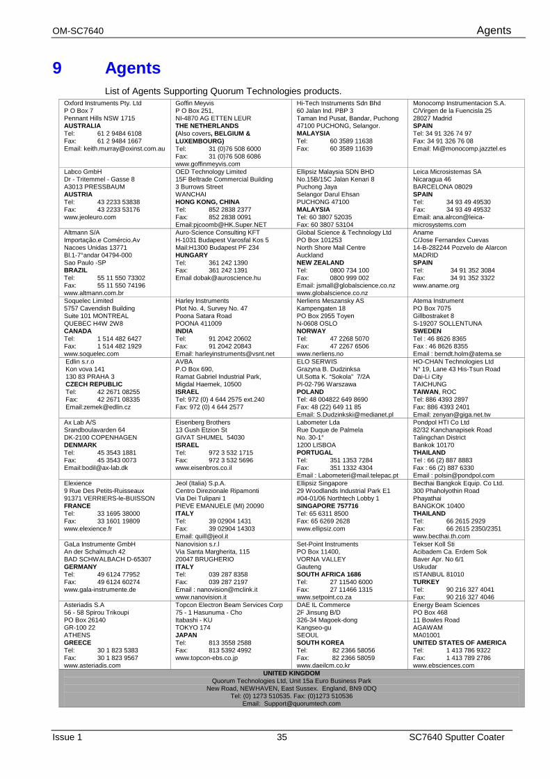
OM-SC7640 Agents
Issue 1 35 SC7640 Sputter Coater
9 Agents
List of Agents Supporting Quorum Technologies products. Oxford Instruments Pty. Ltd P O Box 7 Pennant Hills NSW 1715 AUSTRALIA Tel: 61 2 9484 6108 Fax: 61 2 9484 1667 Email: [email protected]
Goffin Meyvis P O Box 251, NI-4870 AG ETTEN LEUR THE NETHERLANDS (Also covers, BELGIUM & LUXEMBOURG) Tel: 31 (0)76 508 6000 Fax: 31 (0)76 508 6086 www.goffinmeyvis.com
Hi-Tech Instruments Sdn Bhd 60 Jalan Ind. PBP 3 Taman Ind Pusat, Bandar, Puchong 47100 PUCHONG, Selangor. MALAYSIA Tel: 60 3589 11638 Fax: 60 3589 11639
Monocomp Instrumentacion S.A. C/Virgen de la Fuencisla 25 28027 Madrid SPAIN Tel: 34 91 326 74 97 Fax: 34 91 326 76 08 Email: [email protected]
Labco GmbH Dr - Tritemmel - Gasse 8 A3013 PRESSBAUM AUSTRIA Tel: 43 2233 53838 Fax: 43 2233 53176 www.jeoleuro.com
OED Technology Limited 15F Beltrade Commercial Building 3 Burrows Street WANCHAI HONG KONG, CHINA Tel: 852 2838 2377 Fax: 852 2838 0091 Email:[email protected]
Ellipsiz Malaysia SDN BHD No.15B/15C Jalan Kenari 8 Puchong Jaya Selangor Darul Ehsan PUCHONG 47100 MALAYSIA Tel: 60 3807 52035 Fax: 60 3807 53104
Leica Microsistemas SA Nicaragua 46 BARCELONA 08029 SPAIN Tel: 34 93 49 49530 Fax: 34 93 49 49532 Email: [email protected]
Altmann S/A Importação.e Comércio.Av Nacoes Unidas 13771 Bl.1-7°andar 04794-000 Sao Paulo -SP BRAZIL Tel: 55 11 550 73302 Fax: 55 11 550 74196 www.altmann.com.br
Auro-Science Consulting KFT H-1031 Budapest Varosfal Kos 5 Mail:H1300 Budapest PF 234 HUNGARY Tel: 361 242 1390 Fax: 361 242 1391 Email [email protected]
Global Science & Technology Ltd PO Box 101253 North Shore Mail Centre Auckland NEW ZEALAND Tel: 0800 734 100 Fax: 0800 999 002 Email: [email protected] www.globalscience.co.nz
Aname C/Jose Fernandex Cuevas 14-B-282244 Pozvelo de Alarcon MADRID SPAIN Tel: 34 91 352 3084 Fax: 34 91 352 3322 www.aname.org
Soquelec Limited 5757 Cavendish Building Suite 101 MONTREAL QUEBEC H4W 2W8 CANADA Tel: 1 514 482 6427 Fax: 1 514 482 1929 www.soquelec.com
Harley Instruments Plot No. 4, Survey No. 47 Poona Satara Road POONA 411009 INDIA Tel: 91 2042 20602 Fax: 91 2042 20843 Email: [email protected]
Nerliens Meszansky AS Kampengaten 18 PO Box 2955 Toyen N-0608 OSLO NORWAY Tel: 47 2268 5070 Fax: 47 2267 6506 www.nerliens.no
Atema Instrument PO Box 7075 Gillbostraket 8 S-19207 SOLLENTUNA SWEDEN Tel : 46 8626 8365 Fax : 46 8626 8355 Email : [email protected]
Edlin s.r.o Kon vova 141 130 83 PRAHA 3 CZECH REPUBLIC Tel: 42 2671 08255 Fax: 42 2671 08335 Email:[email protected]
AVBA P.O Box 690, Ramat Gabriel Industrial Park, Migdal Haemek, 10500 ISRAEL Tel: 972 (0) 4 644 2575 ext.240 Fax: 972 (0) 4 644 2577
ELO SERWIS Grazyna B. Dudzinksa Ul.Sotta K. “Sokola” 7/2A Pl-02-796 Warszawa POLAND Tel: 48 004822 649 8690 Fax: 48 (22) 649 11 85 Email: [email protected]
HO-CHAN Technologies Ltd N° 19, Lane 43 His-Tsun Road Dai-Li City TAICHUNG TAIWAN, ROC Tel: 886 4393 2897 Fax: 886 4393 2401 Email: [email protected]
Ax Lab A/S Srandboulavarden 64 DK-2100 COPENHAGEN DENMARK Tel: 45 3543 1881 Fax: 45 3543 0073 Email:[email protected]
Eisenberg Brothers 13 Gush Etzion St GIVAT SHUMEL 54030 ISRAEL Tel: 972 3 532 1715 Fax: 972 3 532 5696 www.eisenbros.co.il
Labometer Lda Rue Duque de Palmela No. 30-1° 1200 LISBOA PORTUGAL Tel: 351 1353 7284 Fax: 351 1332 4304 Email : [email protected]
Pondpol HTI Co Ltd 82/32 Kanchanapisek Road Talingchan District Bankok 10170 THAILAND Tel : 66 (2) 887 8883 Fax : 66 (2) 887 6330 Email : [email protected]
Elexience 9 Rue Des Petits-Ruisseaux 91371 VERRIERS-le-BUISSON FRANCE Tel: 33 1695 38000 Fax: 33 1601 19809 www.elexience.fr
Jeol (Italia) S.p.A. Centro Direzionale Ripamonti Via Dei Tulipani 1 PIEVE EMANUELE (MI) 20090 ITALY Tel: 39 02904 1431 Fax: 39 02904 14303 Email: [email protected]
Ellipsiz Singapore 29 Woodlands Industrial Park E1 #04-01/06 Northtech Lobby 1 SINGAPORE 757716 Tel: 65 6311 8500 Fax: 65 6269 2628 www.ellipsiz.com
Becthai Bangkok Equip. Co Ltd. 300 Phaholyothin Road Phayathai BANGKOK 10400 THAILAND Tel: 66 2615 2929 Fax: 66 2615 2350/2351 www.becthai.th.com
GaLa Instrumente GmbH An der Schalmuch 42 BAD SCHWALBACH D-65307 GERMANY Tel: 49 6124 77952 Fax: 49 6124 60274 www.gala-instrumente.de
Nanovision s.r.l Via Santa Margherita, 115 20047 BRUGHERIO ITALY Tel: 039 287 8358 Fax: 039 287 2197 Email : [email protected] www.nanovision.it
Set-Point Instruments PO Box 11400, VORNA VALLEY Gauteng SOUTH AFRICA 1686 Tel: 27 11540 6000 Fax: 27 11466 1315 www.setpoint.co.za
Tekser Koll Sti Acibadem Ca. Erdem Sok Baver Apr. No 6/1 Uskudar ISTANBUL 81010 TURKEY Tel: 90 216 327 4041 Fax: 90 216 327 4046
Asteriadis S.A 56 - 58 Spirou Trikoupi PO Box 26140 GR-100 22 ATHENS GREECE Tel: 30 1 823 5383 Fax: 30 1 823 9567 www.asteriadis.com
Topcon Electron Beam Services Corp 75 - 1 Hasunuma - Cho Itabashi - KU TOKYO 174 JAPAN Tel: 813 3558 2588 Fax: 813 5392 4992 www.topcon-ebs.co.jp
DAE IL Commerce 2F Jinsung B/D 326-34 Magoek-dong Kangseo-gu SEOUL SOUTH KOREA Tel: 82 2366 58056 Fax: 82 2366 58059 www.daeilcm.co.kr
Energy Beam Sciences PO Box 468 11 Bowles Road AGAWAM MA01001 UNITED STATES OF AMERICA Tel: 1 413 786 9322 Fax: 1 413 789 2786 www.ebsciences.com
UNITED KINGDOM Quorum Technologies Ltd, Unit 15a Euro Business Park
New Road, NEWHAVEN, East Sussex. England, BN9 0DQ Tel: (0) 1273 510535. Fax: (0)1273 510536
Email: [email protected]
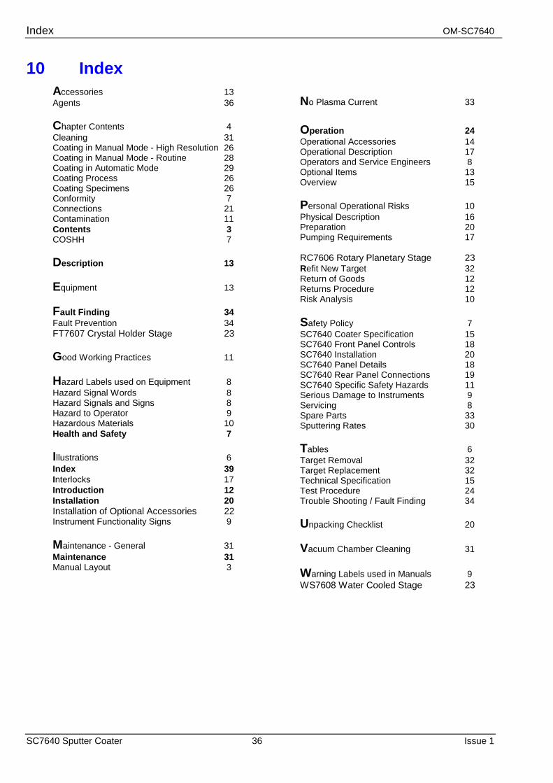
Index OM-SC7640
SC7640 Sputter Coater 36 Issue 1
10 Index Accessories 13 Agents 36 Chapter Contents 4 Cleaning 31 Coating in Manual Mode - High Resolution 26 Coating in Manual Mode - Routine 28 Coating in Automatic Mode 29 Coating Process 26 Coating Specimens 26 Conformity 7 Connections 21 Contamination 11 Contents 3 COSHH 7 Description 13 Equipment 13 Fault Finding 34 Fault Prevention 34 FT7607 Crystal Holder Stage 23 Good Working Practices 11 Hazard Labels used on Equipment 8 Hazard Signal Words 8 Hazard Signals and Signs 8 Hazard to Operator 9 Hazardous Materials 10 Health and Safety 7 Illustrations 6 Index 39 Interlocks 17 Introduction 12 Installation 20 Installation of Optional Accessories 22 Instrument Functionality Signs 9 Maintenance - General 31 Maintenance 31 Manual Layout 3
No Plasma Current 33 Operation 24 Operational Accessories 14 Operational Description 17 Operators and Service Engineers 8 Optional Items 13 Overview 15 Personal Operational Risks 10 Physical Description 16 Preparation 20 Pumping Requirements 17 RC7606 Rotary Planetary Stage 23 Refit New Target 32 Return of Goods 12 Returns Procedure 12 Risk Analysis 10 Safety Policy 7 SC7640 Coater Specification 15 SC7640 Front Panel Controls 18 SC7640 Installation 20 SC7640 Panel Details 18 SC7640 Rear Panel Connections 19 SC7640 Specific Safety Hazards 11 Serious Damage to Instruments 9 Servicing 8 Spare Parts 33 Sputtering Rates 30 Tables 6 Target Removal 32 Target Replacement 32 Technical Specification 15 Test Procedure 24 Trouble Shooting / Fault Finding 34 Unpacking Checklist 20 Vacuum Chamber Cleaning 31 Warning Labels used in Manuals 9 WS7608 Water Cooled Stage 23
Top Related