


Languages
Pages
Legal


VILNIUS UNIVERSITY
SANDRA SVANIDZAITĖ
SPIRAL PROCESS MODEL FOR CAPTURE AND ANALYSIS OF NON-
FUNCTIONAL REQUIREMENTS OF SERVICE-ORIENTED ENTERPRISE
SYSTEMS
Doctoral Dissertation
Physical Sciences, Informatics (09 P)
Vilnius, 2015

The dissertation was written between 2010 and 2014 at Vilnius University
Institute of Mathematics and Informatics.
Scientific supervisor – Prof Dr. Albertas Čaplinskas (Vilnius University
Institute of Mathematics and Informatics, Physical Sciences, Informatics – 09
P).

VILNIAUS UNIVERSITETAS
SANDRA SVANIDZAITĖ
SPIRALINIS PROCESO MODELIS PASLAUGŲ STILIAUS
ARCHITEKTŪROS ĮMONIŲ SISTEMŲ NEFUNKCINIAMS
REIKALAVIMAMS IŠGAUTI IR ANALIZUOTI
Daktaro disertacija
Fiziniai mokslai, informatika (09 P)
Vilnius, 2015

Disertacija rengta 2010 – 2014 metais Vilniaus universiteto Matematikos ir
informatikos institute.
Mokslinis vadovas – prof. dr. Albertas Čaplinskas (Vilniaus universiteto
Matematikos ir informatikos institutas, fiziniai mokslai, informatika – 09 P).

v
Acknowledgments
I would like to express my thanks to all the people who have been in one way
or another involved in the preparation of this thesis.
I would like to thank my scientific supervisor Prof Dr. Albertas Čaplinskas for
support and guidance throughout the process of this dissertation research. He
introduced me to the field of service-oriented architecture and, in particular, to
service-oriented requirement engineering discipline. Throughout four years of
research and study under his supervision, he has been always a great source of
inspiration and encouragement.
I am also grateful for the patience and constructive feedback from other
members of the staff of Vilnius University Institute of Mathematics and
Informatics.

vi
Abstract
Service orientation is a relatively new software development paradigm. It
inherits a number of concepts and principles from earlier paradigms but differs
from these paradigms in the manner in which the separation of concerns in the
software system is done. In addition to this, it provides an additional software
system abstraction layer – business logic layer. Service oriented architecture
(SOA) is an architectural style that implements service-orientation approach.
SOA raises new problems in software requirements engineering. As a result,
new requirements engineering sub-discipline – service-oriented requirements
engineering (SORE) – emerges. SORE focuses mainly on the identification of
services and workflows used to modelling applications and on their reuse. The
thesis highlights existing issues and concerns in SORE and discusses how one
type of service specification issues – non-functional requirements capturing,
analysis and conflicts resolution could be solved. The thesis defines a spiral
process model for capture and analysis of non-functional requirements for
Enterprise Service-Oriented Architecture – ESOA (a sub-style of SOA,
operating in a less open environment than ordinary SOA and aimed at
supporting enterprise business strategy and objectives) systems. This is the
main contribution of the research work. The process model is based on
classical as well as service-oriented RE process models, i*-based modelling
languages, viewpoints that are widely used Enterprise Architecture (EA)
standards and frameworks, service-oriented architecture layers and can be
applied in conjunction with service-oriented systems development
methodologies. The experimental research – a case study – demonstrated that
the proposed process model can be successfully applied to real-world ESOA
systems as it facilitates capturing, analysis and resolution of conflicting non-
functional requirements and improves the system’s quality.

vii
Contents
Acknowledgments ........................................................................................................ v Abstract ....................................................................................................................... vi
List of Figures ................................................................................................................ x List of Tables ................................................................................................................ xi Glossary and Acronyms ............................................................................................ xii Introduction ............................................................................................................... 21
Research Context and Challenges ........................................................................... 21
Problem Statement ................................................................................................... 22 Motivation ................................................................................................................ 23 Aims and Objectives of the Research....................................................................... 25
Research Questions and Hypotheses ....................................................................... 26 Research Design and Research Methods ................................................................ 27 Summary of Research Results .................................................................................. 30 Contributions of the Dissertation ............................................................................ 31
Approbation ............................................................................................................. 32 Outline of the Dissertation....................................................................................... 32
Chapter 1 .................................................................................................................... 34 Preliminaries .............................................................................................................. 34
1.1. Service-Oriented Architecture ...................................................................... 34
1.1.1 Service-Oriented Architecture Principles .............................................. 35 1.1.2 Service-Oriented Architecture Layers ................................................... 38
1.1.3 Service and Service Type ...................................................................... 48 1.2. Enterprise Service-Oriented Architecture ..................................................... 50 1.3. User Requirement Standard Notation Languages ......................................... 51
Chapter 2 .................................................................................................................... 56 State of the Art ........................................................................................................... 56
2.1. Service-Oriented Requirement Engineering ................................................. 56
2.1.1. An Overview of Classic and Service-Oriented Requirement
Engineering: The Process and Techniques .......................................................... 64 2.1.2. Classic RE Process and Models ............................................................. 65 2.1.3. Service-Oriented RE Process and Models ............................................. 67
2.2. Overview of Service-Oriented Software Systems’ Development
Methodologies and Approaches .............................................................................. 70 2.2.1. IBM RUP/SOMA .................................................................................. 71 2.2.2. Service-Oriented Analysis and Design Methodology by Thomas Erl... 72 2.2.3. Service-Oriented Design and Development Methodology by
Papazoglou ........................................................................................................... 73
2.2.4. Service-Oriented Architecture Framework – SOAF ............................. 75 2.2.5. Service-Oriented Unified Process – SOUP ........................................... 77
2.2.6. Characteristics of SOA Methodologies Analysis and Design Phases ... 79 2.2.7. Comparison of SOA development methodologies ................................ 81
2.3. Capturing Non-Functional Requirements for ESOA Systems Using
Viewpoints ............................................................................................................... 84 2.4. Enterprise Architecture Frameworks and Standards ..................................... 88

viii
2.4.1. IEEE 1471:2000 Recommended Practice for Architectural Description
90 2.4.2. ISO/IEC/IEEE 42010:2011 Systems and software engineering –
Architecture description....................................................................................... 91
2.4.3. IEEE P1723 Standard for Service-Oriented Architecture (SOA)
Reference Architecture ........................................................................................ 92 2.4.4. OASIS Reference Architecture Foundation for SOA – OASIS SOA
RAF 92 2.4.5. Zachman Enterprise Architecture Framework....................................... 95
2.4.6. Open Group Architecture Framework – TOGAF .................................. 97 2.4.7. Extended Enterprise Architecture Framework ...................................... 99 2.4.8. Department of Defence Architecture Framework – DoDAF .............. 101 2.4.9. Kruchten’s “4+1”/RUP’s 4 + 1 View Model ....................................... 104 2.4.10. Siemens 4 views method .................................................................. 105
2.4.11. Reference Model for Open Distributed Processing ......................... 107
2.4.12. Comparison of Enterprise Architecture Frameworks ...................... 109 2.5. Summary ..................................................................................................... 116
Chapter 3 .................................................................................................................. 120
Spiral Process Model for Capture and Analysis of Non-Functional Requirements
of Service-Oriented Enterprise Systems ................................................................ 120 3.1. Requirements for Service-Oriented Requirement Engineering Process
Phases .................................................................................................................... 120 3.2. Stakeholders of ESOA Systems .................................................................. 123
3.3. Non-Functional Requirements for ESOA Systems ..................................... 128 3.3.1. Availability .......................................................................................... 130 3.3.2. Performance ......................................................................................... 131
3.3.3. Reliability ............................................................................................ 133 3.3.4. Usability ............................................................................................... 135
3.3.5. Discoverability ..................................................................................... 137
3.3.6. Adaptability ......................................................................................... 138
3.3.7. Composability ...................................................................................... 140 3.3.8. Interoperability .................................................................................... 143
3.3.9. Security ................................................................................................ 144 3.3.10. Scalability ........................................................................................ 146
3.3.11. Extensibility ..................................................................................... 147 3.3.12. Testability ........................................................................................ 148 3.3.13. Auditability ...................................................................................... 149 3.3.14. Modifiability .................................................................................... 150
3.4. Spiral Process Model for Capture and Analysis of Non-Functional
Requirements of Service-Oriented Enterprise Systems ......................................... 151 3.4.1. Composition of ESOA Viewpoints ..................................................... 155
3.5. Summary ..................................................................................................... 158
The Discussion of Spiral Process Model Viewpoints Mapping to Architecture
Domains and Applicability to Use It in Conjunction with Service-Oriented
Architecture Systems Development Methodologies ............................................. 158 Chapter 4 .................................................................................................................. 164
A Case Study: Enterprise Service-Oriented Insurance System .......................... 164 4.1. Definition of ESOA Viewpoints ................................................................. 165

ix
4.2. Identification of Requirement Conflicts, Modelling User Concerns and
NFRs Using GRL and UCM, Developing Alternative Solutions, Elaborating
Solutions and Performing Judgment and Trade-off in Consumer Viewpoint ....... 176 4.2.1. Identification of Requirement Conflicts in Customer Viewpoint ....... 176
4.2.2. Modelling of User Concerns and NFRs in Consumer Viewpoint using
GRL and UCM .................................................................................................. 177 4.2.3. Developing of Alternative Solutions in Consumer Viewpoint ............ 181 4.2.4. Elaborating Solutions and Performing Judgment and Trade-off in
Consumer Viewpoint ......................................................................................... 182
4.3.1. Identification of Requirement Conflicts in Business Process Viewpoint
182 4.3.2. Modelling of User Concerns and NRFs in Business Process Viewpoint
using GRL and UCM ......................................................................................... 183 4.3.3. Developing of Alternative Solutions in Business Process Viewpoint . 185
4.3.4. Elaborating Solutions and Performing Judgement and Trade-off in
Business Process Viewpoint .............................................................................. 185 4.4.1. Identification of Requirement Conflicts between Customer and
Business Process Viewpoints ............................................................................ 186 4.4.2. Modelling of User Concerns and NFRs in Customer and Business
Process Viewpoints using GRL and UCM ........................................................ 187 4.4.3. Developing of Alternative Solutions in Customer and Business Process
Viewpoint .......................................................................................................... 189 4.4.4. Elaborating Solutions and Performing Judgment and Trade-off in
Customer and Business Process Viewpoints ..................................................... 190 4.5. Summary ..................................................................................................... 191
Chapter 5 .................................................................................................................. 194
Discussion of Issues and Limitations ..................................................................... 194 5.1. Open Problems ............................................................................................ 195
Results and Conclusions .......................................................................................... 196
References ................................................................................................................. 199
List of Publications .................................................................................................. 212

x
List of Figures
Figure 1-1. Service-Oriented Architecture Principles (Erl, 2008) .............................. 36 Figure 1-2. Three Primary Service Layers (Erl, 2005) ............................................... 42
Figure 1-3. SOA Reference Architecture Layers (SOA-RA, 2011) ........................... 42 Figure 1-4. Service Types by Erl (Erl, 2008) ............................................................. 49 Figure 1-5. Structure of Enterprise Service-Oriented Architecture (based on Minoli,
2008) ............................................................................................................................ 51 Figure 1-6. GRL notation (ITU-T, 2008) ................................................................... 53
Figure 1-7. UCM notation (ITU-T, 2008) .................................................................. 55 Figure 2-1. Requirements’ Generation Model – RGM (Arthur and Gröner, 2005) ... 67 Figure 2-2. Systematic SORE Process IDEF0 Detailed Diagram (Flores, et al, 2010)
..................................................................................................................................... 68 Figure 2-3. Phases of the Service-Oriented Design and Development ....................... 75 Figure 2-4. Service-Oriented Architecture Framework Execution View (Erradi, et. al,
2006) ............................................................................................................................ 76
Figure 2-5. SOUP and RUP Model (SOUP)............................................................... 78 Figure 2-6. Overlaid SOUP and XP Processes (SOUP) ............................................. 78
Figure 2-7. Conceptual Framework of IEEE 1471:2000 (partial view; Minoli, 2008)
..................................................................................................................................... 91 Figure 2-8. Conceptual Framework of IEEE 1471:2000 (larger view; IEEE Std
1471:2000) ................................................................................................................... 91 Figure 3-1. Stakeholders of ESOA System - Onion Diagram .................................. 128
Figure 3-2. Sub-Attributes of Composability (Choi et al, 2007) .............................. 141 Figure 3-3. ESOA NFRs Negotiation Spiral Model ................................................. 153 Figure 3-4. Tabular Method for Checking NFRs for Mutual Consistency
(independent Requirements are Marked with “0”, Overlapping – “10”, Conflicting –
“1”) ............................................................................................................................ 154 Figure 4-1. New Auto Policy Creation Business Process ......................................... 167
Figure 4-2. New Auto Claim Creation Process ........................................................ 168 Figure 4-3. UCM Diagram: Business Process – Insure New Customer ................... 178 Figure 4-4. UCM Diagram: Business Process – Insure New Customer Sub-Process –
Log In......................................................................................................................... 178 Figure 4-5. UCM Diagram: Business Process – Register Claim for an Existing
Customer .................................................................................................................... 179 Figure 4-6. GRL Diagram: Consumer Viewpoint User Concerns and Non-Functional
Requirements ............................................................................................................. 180 Figure 4-7. Business Process Viewpoint User Concerns and Non-Functional
Requirements Modelling Using GRL ........................................................................ 184
Figure 4-8. Customer and Business Process Viewpoint User Concerns and Non-
Functional Requirements Modelling Using GRL ...................................................... 188
xi
List of Tables
Table 2-1. IBM RUP/SOMA, SOAF, Methodology by Tomas Erl Comparison
According to Characteristics........................................................................................ 81 Table 2-2. Methodology by Papazoglou and SOUP Comparison According to
Characteristics.............................................................................................................. 83 Table 2-3. TOGAF ADM Views (TOGAF 9.1, 2011) ............................................... 98 Table 2-4. Comparison/Mapping of Enterprise Architecture Framework
Views/Viewpoints...................................................................................................... 110 Table 3-1. Comparison/Mapping of Enterprise Architecture Framework
Views/Viewpoints including process model for ESOA NFRs Capture and Analysis
................................................................................................................................... 159 Table 4-1. PEST Analysis for Insurance4You Company Political, Economic, Social
and Technological Factors ......................................................................................... 165 Table 4-2. SWOT Analysis for Insurance4You Company Strengths, Weaknesses,
Opportunities and Threats.......................................................................................... 166
Table 4-3. Consumer Viewpoint Non-Functional Requirements ............................. 168
Table 4-4. Business Process Viewpoint Non-Functional Requirements .................. 171 Table 4-5. Service Viewpoint Non-Functional Requirements .................................. 174 Table 4-6. Consumer Viewpoint Non-Functional Requirements’ Check for
Consistency ................................................................................................................ 177 Table 4-7. Conflicting Non-Functional Requirements in Consumer Viewpoint ...... 181
Table 4-8. Overlapping Requirements in Consumer Viewpoint .............................. 181 Table 4-9 Business Process Viewpoint Non-Functional Requirements’ Check for
Consistency ................................................................................................................ 183
Table 4-10. Conflicting Non-Functional Requirements in Business Process
Viewpoint .................................................................................................................. 185
Table 4-11. Overlapping Non-Functional Requirements in Business Process
Viewpoint .................................................................................................................. 185
Table 4-12. Customer and Business Process Viewpoints Non-Functional
Requirements’ Check for Consistency ...................................................................... 187 Table 4-13. Conflicting Non-Functional Requirements in Consumer and Business
Process Viewpoints .................................................................................................... 189
Table 4-14 Overlapping Non-Functional Requirements in Consumer and Business
Process Viewpoint ..................................................................................................... 190

xii
Glossary and Acronyms
Architecture of a system – fundamental concepts or properties of a system in
its environment embodied in its elements, relationships, and in the
principles of its design and evolution (ISO/IEC/IEEE 42010:2011;
SOA-RM, 2006).
Architecture description (AD) – work product used to express architecture
(ISO/IEC/IEEE 42010:2011; SOA-RM, 2006).
Architecture description language (ADL) – any form of expression for use
in architecture descriptions. An ADL provides one or more model kinds
as means for framing some concerns for its audience of stakeholders.
An ADL can be narrowly focused, defining a single model kind, or
widely focused to provide several model kinds, optionally organized
into viewpoints. Often an ADL is supported by automated tools to aid
the creation, use and analysis of its models. Examples of ADLs are as
follows: Rapide (Luckham, 1995), Wright (WEB, j), SysML (OMG,
2008), ArchiMate (WEB, k; ISO/IEC/IEEE 42010:2011).
Architecture framework – conventions, principles and practices for the
description of architectures established within a specific domain of
application and/or community of stakeholders. For example, the
Reference Model of Open Distributed Processing (RM-ODP) is an
architecture framework (ISO/IEC/IEEE 42010:2011).
Architecture rationale – records explanation, justification or reasoning about
architecture decisions that have been made. The rationale for a decision
can include the basis for a decision, alternatives and trade-offs
considered, potential consequences of the decision and citations to
sources of additional information (ISO/IEC/IEEE 42010:2011).
Architecture view – work product expressing the architecture of a system
from the perspective of specific system concerns (ISO/IEC/IEEE
42010:2011; SOA-RM, 2006).
Architecture viewpoint – work product establishing the conventions for the
construction, interpretation and use of architecture views to frame
specific system concerns (ISO/IEC/IEEE 42010:2011; SOA-RM, 2006).
Business Process Modelling Notation (BPMN) provides businesses with the
capability of understanding their internal business procedures in a
graphical notation and gives organizations the ability to communicate
these procedures in a standard manner. Furthermore, the graphical
notation facilitates the understanding of the performance collaborations

xiii
and business transactions between the organizations. This ensures that
businesses understands themselves and participants in their business and
enables organizations to adjust to new internal and business-to-business
(B2B) business circumstances quickly (WEB, d).
Case study is an empirical research method that aims at investigating some
phenomena in this context (Runeson & Höst, 2009).
Conceptual analysis – the analysis of concepts, terms, variables, constructs,
definitions, assertions, hypotheses, and theories that involve examining
these for clarity and coherence, critically scrutinizing their logical
relations, and identifying assumptions and implications (Machado and
Silva, 2007).
Concern – interest in a system relevant to one or more of its stakeholders. A
concern pertains to any influence on a system in its environment,
including developmental, technological, business, operational,
organizational, political, economic, legal, regulatory, ecological and
social influences (ISO/IEC/IEEE 42010:2011). A stakeholder’s concern
should not be confused with either a need or a formal requirement. A
concern, as understood here, is an area or topic of interest. Within that
concern, system stakeholders may have many different requirements
(SOA-RM, 2006).
Component-based software engineering (CBSE) is a branch of software
engineering that emphasizes the separation of concerns in respect of the
wide-ranging functionality available throughout a given software
system. It is a reuse-based approach to defining, implementing and
composing loosely coupled independent components into systems. This
practice aims to bring about an equally wide-ranging degree of benefits
in both the short-term and the long-term for the software itself and for
organizations that sponsor such software.
Common Object Request Broker Architecture (CORBA) – OMG's open,
vendor-independent architecture and infrastructure that computer
applications use to work together over networks. Using the standard
protocol IIOP, a CORBA-based program from any vendor, on almost
any computer, operating system, programming language, and network,
can interoperate with a CORBA-based program from the same or
another vendor, on almost any other computer, operating system,
programming language, and network (WEB, m).
Constructive research – a research procedure for producing innovative
constructions, intended to solve the problems encountered in the real
world and to make some contribution to the theory of the discipline in
which it is applied (Lukka, 2003; Crnkovic, 2010).

xiv
Correspondence defines a relation between architecture description elements.
Correspondences are used to express architecture relations of interest
within an architecture description (or between architecture descriptions)
(ISO/IEC/IEEE 42010:2011).
Correspondence rules govern correspondences. They are used to enforce
relations within an architecture description (or between architecture
descriptions) (ISO/IEC/IEEE 42010:2011).
Commercial off-the-shelf (COTS) describes software or hardware products
that are ready-made and available for sale to the general public. For
example, Microsoft Office is a COTS product that is a packaged
software solution for businesses. COTS products are designed to be
implemented easily into existing systems without the need for
customization.
Distributed Component Object Model (DCOM) is a set of Microsoft
concepts and program interfaces in which client program objects can
request services from server program objects on other computers in a
network. DCOM is based on the Component Object Model (COM),
which provides a set of interfaces allowing clients and servers to
communicate within the same computer (WEB, o).
Distributed processing – information processing in which discrete
components may be located in different places, and where
communication between components may suffer delay or may fail
(ISO/IEC 10746-2:1996).
Department of Defence Architecture Framework (DoDAF) is an
architecture framework for the United States Department of Defence
(DoD) that provides visualization infrastructure for specific
stakeholders’ concerns through viewpoints organized by various views.
These views are artefacts for visualizing, understanding, and
assimilating the broad scope and complexities of an architecture
description through tabular, structural, behavioural, ontological,
pictorial, temporal, graphical, probabilistic, or alternative conceptual
means (DoDAF v2.02, 2010).
Domain framework – a framework capturing knowledge and expertise in a
particular problem domain. Frameworks are built for various purposes
and usually they are specific to one or several domains. Sometimes
domain frameworks are referred to as enterprise application
frameworks.
Electronic Business using eXtensible Markup Language (ebXML) commonly known as e-business XML, is a family of XML based
standards sponsored by OASIS and UN/CEFACT whose mission is to

xv
provide an open, XML-based infrastructure that enables the global use
of electronic business information in an interoperable, secure, and
consistent manner by all trading partners (WEB, x).
Environment – context determining the setting and circumstances of all
influences upon a system. The environment of a system includes
developmental, technological, business, operational, organizational,
political, economic, legal, regulatory, ecological and social influences
(ISO/IEC/IEEE 42010:2011).
Enterprise – any collection of organizations that has a common set of goals.
For example, an enterprise could be a government agency, a whole
corporation, a division of a corporation, a single department, or a chain
of geographically distant organizations linked together by common
ownership. (TOGAF, 9.1)
Enterprise service bus (ESB) is a software architecture middleware used for
designing and implementing communication between mutually
interacting software applications in a service-oriented architecture. It is
a specialty variant of the more general client server model and promotes
agility and flexibility with regard to communication between
applications. Its primary use is in enterprise application integration of
heterogeneous and complex landscapes (WEB, ak).
Kerberos – a network authentication protocol. It is designed to provide strong
authentication for client/server applications by using secret-key
cryptography. The Kerberos protocol uses strong cryptography so that a
client can prove its identity to a server (and vice versa) across an
insecure network connection. After a client and server have used
Kerberos to prove their identity, they can also encrypt all of their
communications to assure privacy and data integrity as they go about
their business (WEB, ab).
Microsoft .NET is an integral part of many applications running on Windows
and provides common functionality for those applications to run. For
developers, the .NET Framework provides a comprehensive and
consistent programming model for building applications that have
visually stunning user experiences and seamless and secure
communication (WEB, r).
Mission Statement – a written declaration of an organization’s core purpose
and focus that normally remains unchanged over time. Properly crafted
mission statements (1) serve as filters to separate what is important from
what is not, (2) clearly state which markets will be served and how, and
(3) communicate a sense of intended direction to the entire organization.
A mission is different from a vision in that the former is the cause and
the latter is the effect. A mission is something to be accomplished

xvi
whereas a vision is something to be pursued for that accomplishment
(WEB, e).
Ministry of Defence Architecture Framework (MODAF) is an
internationally recognised enterprise architecture framework developed
by the Ministry of Defence (MOD) to support defence planning and
change management activities. It does this by enabling the capture and
presentation of information in a rigorous, coherent and comprehensive
way that aids the understanding of complex issues WEB (ag).
Model kinds are conventions for a type of modelling. Examples of model
kinds include data flow diagrams, class diagrams, Petri nets, balance
sheets, organization charts and state transition models (ISO/IEC/IEEE
42010:2011).
Open Distributed Processing (ODP) is an attempt to standardise OSI
application layer communications architecture. ODP is a natural
progression from OSI, broadening the target of standardisation from the
point of interconnection to the end system behaviour. The objective of
ODP is to enable the construction of distributed systems in a multi-
vendor environment through the provision of a general architectural
framework that such systems must conform to. One of the cornerstones
of this framework is a model of multiple viewpoints which enables
different participants to observe a system from a suitable perspective
and a suitable level of abstraction WEB (ah).
Oracle Java Enterprise Edition (JAVA EE) is an Oracle Enterprise Java
computing platform. The platform provides an API and runtime
environment for developing and running enterprise software, including
network and web services, and other large-scale, multi-tiered, scalable,
reliable, and secure network applications (WEB, s).
Perspective is a set of facts observed and modelled according to a particular
modelling aspect of reality.
PEST Analysis is a useful tool for understanding market growth or decline,
and as such the position, potential and direction for a business. PEST is
an acronym for Political, Economic, Social and Technological factors,
which are used to assess the market for a business or organizational
unit. PEST analysis is used for business and strategic planning,
marketing planning, business and product development and research
reports. As PEST factors are essentially external, completing a PEST
analysis is helpful prior to completing a SWOT analysis (a SWOT
analysis - Strengths, Weaknesses, Opportunities, Threats - is based
broadly on half-internal and half-external factors) (WEB, f).

xvii
Reference Architecture is an architectural design pattern that indicates how
an abstract set of mechanisms and relationships realizes a predetermined
set of requirements. Reference architecture models the abstract
architectural elements in the domain of interest independent of the
technologies, protocols, and products that are used to implement a
specific solution for the domain. Reference architecture elaborates
further on the reference model to show a more complete picture that
includes showing what is involved in realizing the modelled entities,
while staying independent of any particular solution but instead applies
to a class of solutions. It is possible to define reference architectures at
many levels of detail or abstraction, and for many different purposes.
Reference architecture is not a concrete architecture; i.e., depending on
the requirements being addressed by the reference architecture, it
generally will not completely specify all the technologies, components
and their relationships in sufficient detail to enable direct
implementation (SOA-RM, 2006).
Reference Model is an abstract framework for understanding significant
relationships among the entities of some environment that enables the
development of specific architectures using consistent standards or
specifications supporting that environment. A reference model consists
of a minimal set of unifying concepts, axioms and relationships within a
particular problem domain and is independent of specific standards,
technologies, implementations, or other concrete details (SOA-RM,
2006.
Remote Method Invocation (RMI) enables the programmer to create
distributed Java technology-based to Java technology-based
applications, in which the methods of remote Java objects can be
invoked from other Java virtual machines, possibly on different hosts.
RMI uses object serialization to marshal and unmarshal parameters and
does not truncate types, supporting true object-oriented polymorphism
(WEB, n).
Remote Procedure Call (RPC) is a powerful technology for creating
distributed client/server programs. RPC is an interprocess
communication technique that allows client and server software to
communicate (WEB, p).
Security Assertions Markup Language (SAML) is an XML-based, open-
standard data format for exchanging authentication and authorization
data between parties, in particular, between an identity provider and a
service provider. SAML is a product of the OASIS Security Services
Technical Committee. The first version of SAML was released in 2001,
the second version was published in 2005 (WEB, ac).

xviii
Service-Oriented Architecture (SOA) is a paradigm for organizing and
utilizing distributed capabilities that may be under the control of
different ownership domains. It provides a uniform means to offer,
discover, interact with and use capabilities to produce desired effects
consistent with measurable preconditions and expectations (SOA-RM,
2006.
Service Level Agreement (SLA) is a contract between a service provider and
its internal or external customers that documents what services the
provider will furnish WEB (ai).
SOA Ecosystem is a network of discrete processes and machines that, together
with a community of people, creates, uses, and governs specific services
as well as external suppliers of resources required by those services
(SOA-RAF, 2012).
Simple Object Access Protocol (SOAP) is a messaging protocol that allows
programs that run on disparate operating systems to communicate using
Hypertext Transfer Protocol (HTTP) and its Extensible Markup
Language (XML). SOAP defines the XML-based message format that
Web service-enabled applications use to communicate and inter-operate
with each other over the Web. The heterogeneous environment of the
Web demands that applications support a common data encoding
protocol and message format. SOAP is a standard for encoding
messages in XML that invoke functions in other applications. SOAP is
analogous to Remote Procedure Calls (RPC), used in many technologies
such as DCOM and CORBA, but eliminates some of the complexities of
using these interfaces (WEB, u).
Systems Development Life Cycle (SDLC) is a conceptual model used in
project management that describes the stages involved in an information
system development project, from an initial feasibility study through the
maintenance of the completed application. Various SDLC
methodologies have been developed to guide the processes involved,
including the waterfall model (which was the original SDLC method);
rapid application development (RAD); joint application development
(JAD); the fountain model; the spiral model; build and fix; and
synchronize-and-stabilize. Frequently, several models are combined into
some sort of hybrid methodology. Documentation is crucial regardless
of the type of the model chosen or devised for any application, and is
usually done in parallel with the development process. Some methods
work better for specific types of projects, but in the final analysis, the
most important factor for the success of a project may be how closely
the particular plan was followed (WEB, g).
System – a collection of components organized to accomplish a specific
function or set of functions (SOA-RM, 2006).

xix
Stakeholder – individual, team, organization (or classes thereof), having an
interest in a system (ISO/IEC/IEEE 42010:2011; SOA-RM, 2006).
SWOT analysis is an extremely useful tool for understanding and decision-
making for all sorts of situations in business and organizations. SWOT
is an acronym for Strengths, Weaknesses, Opportunities and Threats.
The SWOT analysis headings provide a good framework for reviewing
the strategy, position and direction of a company or business
proposition, or any other idea (WEB, h).
Transport Layer Security (TLS) and its predecessor Secure Sockets Layers
Protocol (SSL) are cryptographic protocols designed to provide
communication security over the network. They use X.509 certificates
and asymmetric cryptography to authenticate the counterparty with
whom they are communicating, and to exchange a symmetric key. This
session key is then used to encrypt data flowing between the parties.
This allows for data/message confidentiality (WEB, aa).
Vision Statement – an aspirational description of what an organization would
like to achieve or accomplish in the mid-term or long-term future. It is
intended to serve as a clear guide for choosing current and future
courses of action (WEB, al).
Web Services Definition Language (WSDL) is an XML-based interface
definition language that is used for describing the functionality offered
by a web service. WSDL provides a machine-readable description of
how the service can be called, what parameters it expects, and what data
structures it returns. It thus serves a purpose that corresponds roughly to
that of the method signature in a programming language (WEB, t).
Web Services Business Process Execution Language (WS-BPEL) is an
XML-based language that allows Web services in a service-oriented
architecture to interconnect and share data. Programmers use BPEL to
define how a business process that involves web services will be
executed. BPEL messages are typically used to invoke remote services,
orchestrate process execution and manage events and exceptions. BPEL
is often associated with Business Process Management Notation
(BPMN), a standard for representing business processes graphically. In
many organizations, analysts use BPMN to visualize business processes
and developers transform the visualizations to BPEL for execution
(WEB, v).
Web Services Security (WS - Security) is a proposed IT industry standard
that addresses security when data is exchanged as part of a Web service.
WS-Security is one of a series of specifications that include the
Business Process Execution Language (BPEL), WS-Coordination, and
WS-Transaction. WS-Security specifies enhancements to SOAP

xx
(Simple Object Access Protocol) messaging aimed at protecting the
integrity and confidentiality of a message and authenticating the sender.
WS-Security also specifies how to associate a security token with a
message, without specifying what kind of token is to be used. It does
describe how to encode X.509 certificates and Kerberos tickets. In
general, WS-Security is intended to be extensible so that new security
mechanisms can be used in the future (WEB, w).
Web Services Interoperability (WS-I) – a specification from the Web
Services Interoperability industry consortium (WS-I) provides
interoperability guidance for core Web Services specifications such as
SOAP, WSDL, and UDDI. The profile uses Web Services Description
Language (WSDL) to enable the description of services as sets of
endpoints operating on messages (WEB, z).
Web Services Transactions (WS-Tx) is a set of XML markup specifications
designed to permit the use of open, standard protocols for secure,
reliable transactions across the Web. Three constituent standards: WS-
Coordination, WS-AtomicTransaction, WS-BusinessActivity were
created to accommodate two typical transaction patterns: individual
atomic transactions that represent the building blocks for more complex
transactions among peers and partners, Web-based interactions that
result in the exchange of goods, information, or services, usually called
business activities (WEB, af).
The Unified Profile for DoDAF/MODAF (UPDM) is the product of an
Object Management Group (OMG) initiative to develop a modelling
standard that supports both the USA Department of Defence
Architecture Framework (DoDAF) and the UK Ministry of Defence
Architecture Framework (MODAF). The current UPDM - the Unified
Profile for DoDAF and MODAF was based in earlier work with the
same acronym and a slightly different name – the UML Profile for
DoDAF and MODAF WEB (aj).

21
Introduction
Research Context and Challenges
Service-Oriented Architecture (SOA) is a paradigm for organizing and
utilizing distributed capabilities that may be under the control of different
ownership domains (SOA-RM, 2006). In general, people and organizations
create capabilities to solve the problems they face in the course of their
business. It is natural to think of one person’s needs being met by capabilities
offered by someone else, or, in the world of distributed computing, one
computer agent’s requirements being met by a computer agent belonging to a
different owner. The perceived value of SOA is that it provides a powerful
framework for matching needs and capabilities and for combining capabilities
to address those needs. Visibility, interaction, and effect are key concepts for
describing the SOA paradigm. Visibility refers to the capacity for those with
needs and those with capabilities to be able to see each other. This is typically
done by providing descriptions for such aspects as functions and technical
requirements, related constraints and policies, and mechanisms for access or
response. The descriptions need to be in a form in which their syntax and
semantics are widely accessible and understandable. Interaction is the activity
of using a capability. Interaction proceeds through a series of information
exchanges and invoked actions. At the interaction stage, the description of real
world effects establishes the expectations of those using the capability.
Needless to say, it is not possible to describe every effect from using a
capability. A cornerstone of SOA is that capabilities can be used without the
need to know all the details. The service is a central concept of SOA (Erl,
2005; Erl, 2008). It combines the following related ideas: the capability to
perform work for another, the specification of the work offered for another, the
offer to perform work for another. The concepts of visibility, interaction, and

22
effect apply directly to services in the same manner as these were described for
the general SOA paradigm.
While both needs and capabilities exist independently of SOA, in SOA,
services are the mechanism by which needs and capabilities are brought
together. SOA is a means of organizing solutions that promotes reuse, growth
and interoperability. It is not itself a solution to domain problems but rather an
organizing and delivery paradigm that enables one to get more value from use
both of capabilities which are locally “owned” and those under the control of
others. It also enables one to express solutions in a way that makes it easier to
modify or evolve the identified solution or to try alternate solutions. In addition
to this, SOA does not provide any domain elements of a solution that do not
exist without SOA.
Problem Statement
The subject of the thesis research is capture and analysis of non-functional
requirements in ESOA systems starting from the highest abstraction level –
enterprise strategy – where business goals are elicited, deriving system non-
functional requirements from business goals and refining them until concrete
non-functional requirements are produced for each service in the ESOA
system.
Software system requirements are normally divided into functional and non-
functional requirements. Functional requirements focus on to what extent the
software system actually does what it is expected to do. Non-functional
requirements, on the other hand, are said to be the constraints on the system
functions and are less obvious and harder to identify. As a result, non-
functional requirements receive less attention and thus become more critical.
The choice to use an ESOA approach depends on several factors including the
architecture’s ultimate ability to meet functional and non-functional
requirements. Usually, architecture needs to satisfy many non-functional
requirements in order to achieve enterprise business goals.

23
The research aims to define a process model for capture and analysis of non-
functional requirements as each stakeholder group involved in the ESOA
initiative usually have different expectations regarding system quality
characteristics and there is a necessity to be able to negotiate and trade-off
these differences.
Motivation
Many large software projects are ill-defined as a result of the high level of
complexity. It becomes difficult not only to fully specify system requirements
but even to understand all aspects of the system.
According to (SOUP; Svanidzaite, 2014b) SOA/ESOA projects potentially
suffer from one or more of the following problems:
They are significantly more complex than typical software projects,
because they require a larger, cross-functional team along with
correspondingly more complex inter-team communication and logistics;
Usually it is hard to define the scope and boundaries of a project. As a
result, the vision for the final result is often not clear at the project
inception;
SOA can have a very positive impact on an enterprise, but, on the other
hand, the development and replacement of legacy systems can be very
expensive;
SOA/ESOA project has a higher risk of failure than other traditional
software development projects.
Despite these problems, SOA/ESOA approaches are gaining popularity and are
used for more and more complex systems. Having this in mind, SOA/ESOA
projects require much more sophisticated requirement gathering and analysis
techniques.
While for previous paradigms we have well-researched and stable
requirements engineering (RE) processes and techniques, in service-oriented
requirement engineering (SORE) such processes and techniques still are under
24
research (Flores et al, 2009; Flores et al, 2010). SORE like traditional
requirement engineering, concerns with the specification and analysis of
system requirements and constraints but its focus is on the identification of
services and workflows used to modelling applications and on their reuse.
Several service-oriented system development methodologies and approaches
were proposed but they are not aimed at structuring SORE process, lack details
and procedures for requirements gathering and analysis, as a result, further
research is required.
Research by (Bano et al, 2010) suggests that SORE faces with four main
categories of issues and challenges: service specification, service discovery,
service knowledge management, and service composition issues (2.1 Service-
Oriented Requirement Engineering).
Service specification issues are the ones of great importance for ESOA because
the system is only as good as its requirements are. As a result, our research
focuses on the resolution of the following concern: capturing and analysing
non-functional requirements of ESOA systems, finding conflicting
requirements and proposing an approach how to resolve them.
It is suggested by (Leite & Freeman, 1991; Sommerville & Sawyer, 1997;
Russo et al, 1999; Nuseibeh & Easterbrook, 2000) that system requirements
should be elicited and defined from different viewpoints. For any given
viewpoint of the system many aspects will be hidden and only ones actual to
the viewpoint will be depicted in details. As a consequence, multiple
viewpoints need to be considered in order to fully understand and specify the
system-of-interest. Viewpoints can be used to improve system requirements
gathering, analysis and conflict resolution process.
Furthermore, i* (pronounced "i star") is a framework (Yu, 2009) suitable for an
early phase system modelling in order to understand the problem domain. i*-
based modelling language can be used to model viewpoints when specifying
system requirements as it allows to model both as-is and to-be business
models. It covers both actor-oriented and goal-oriented modelling. The i*
models answer the question who (actor) and why (goal), not what (system

25
function). The i* framework is a part of a User Requirements Notation (URN)
international standard. The URN standard combines two sub-languages
(Amyot & Mussbacher, 2011): Goal-oriented Requirement Language (GRL)
and Use Case Maps (UCM) notation. URN is the first international standard
that addresses business goals and scenarios and links between them in a
graphical way.
As SORE has emerged recently, there are no works that deal with Service
Specification issues employing viewpoints and User Requirements Notation
(URN) standard languages directly. Having this in mind, further research is
required.
Aims and Objectives of the Research
The research aims to develop a process model that allows a system analyst to
capture and analyse non-functional requirements for enterprise service-oriented
systems that are designed incorporating traditional and service-oriented
requirement gathering process models, conflicts management approaches and
techniques, EA standards and frameworks. In order to achieve this aim, the
following research objectives have been stated:
1. To evaluate the state of affairs in SORE and all other interrelated
enterprise and service-oriented architecture domain areas including
service-oriented systems development methodologies, enterprise
architecture standards and frameworks that could be used for non-
functional requirements definition conflicts resolution in ESOA
systems;
2. To propose a set of stakeholders for ESOA systems and highlight the
main differences between stakeholders for traditional systems and these;
3. To define a set of quality attributes (non-functional requirements) for
ESOA by drawing the main attention to their differences in respect of
traditional systems non-functional requirements;

26
4. To develop a process model for non-functional requirements capturing
and analysis that includes a process for conflict resolution between
different stakeholder groups.
Research Questions and Hypotheses
The main questions that need to be answered in this research are the following:
How mature is Service-Oriented Requirement Engineering (SORE)
currently? What are the main issues and challenges of it? What SORE
process models are already created? Are they mature enough to ensure
successful SOA/ESOA systems development?
What service-oriented systems development approaches and
methodologies are created? Are they mature enough to ensure
successful SOA/ESOA systems development? Can analysis and design
creation phases of these methodologies and approaches be used to solve
SORE issues and challenges successfully?
How do SOA/ESOA systems non-functional requirements differ from
traditional systems non-functional requirements? Do SORE or service-
oriented systems development methodologies and approaches provide
solutions for non-functional requirements capturing and analysis?
How can traditional requirement engineering processes and their models
be used to solve SORE issues and challenges? To what extent can
traditional requirements conflicts negotiation approaches be used to
solve enterprise systems non-functional requirements conflicts? How
can enterprise service-oriented systems non-functional requirements
conflicts be solved?
Can viewpoints that are usually used when designing enterprise
architectures be used to structure and analyse enterprise service-oriented
systems non-functional requirements? Can i*-based modelling
languages be used to model and negotiate SOA/ESOA non-functional
requirements?

27
To answer these questions, the following hypotheses have been stated:
H1. There exist service-oriented systems development methodologies
such as IBM RUP/SOMA, SOAF, SOUP, service-oriented analysis and
design methodology by Thomas Erl, service-oriented design and
development methodology by Papazoglou that can be used to create
service-oriented requirement engineering process models;
H2. Traditional requirement gathering, conflicts management
approaches and techniques can at least to some extent be used to
capture, analyse and negotiate enterprise service-oriented systems non-
functional requirements;
H3. i*-based modelling languages and viewpoints that are widely used
in Enterprise Architecture (EA) standards and frameworks can be used
to solve conflicting non-functional requirements in SOA/ESOA
systems;
H4. A process model for enterprise service-oriented systems non-
functional requirements capturing and analysis can be developed
incorporating traditional requirements gathering, conflicts management
approaches and techniques, i*-based modelling languages and
viewpoints.
Research Design and Research Methods
The research design of present thesis is of theoretical and empirical nature, as it
is usual in the field of Informatics. Service-oriented requirement engineering is
a relatively young research and development area. The research in this area is
still in its infancy. It means that a relatively large amount of library research is
required in order to define the exact structure of a problem, and to gain a better
understanding of the environment within which the problem arises. In this
context, the best way of solving the problem of theoretical and empirical nature
is constructive research (Mingers, 2001). Furthermore, any dissertation
research is a small-scale research from both financial and time points of view.

28
It means that in such research it is too expensive and practically impossible to
ensure high statistical reliability and high level statistical significance. Thus,
despite its possible biases, the case study methodology is the only practically
acceptable methodology to validate the research results.
Taking into account all that was discussed above, the research design provides
three distinctive research phases: conceptual analysis (Laurence & Margolis,
2003) of related work, constructive research that aims to develop a process
model for ESOA non-functional requirements capture and analysis and
experimental investigation – a case study that validates the designed process
model.
Conceptual analysis is the analysis of concepts, terms, variables, constructs,
definitions, assertions, hypotheses, and theories. It involves examining these
for clarity and coherence, critically scrutinizing their logical relations, and
identifying assumptions and implications (Machado & Silva, 2007). The goal
of conceptual analysis is to increase the conceptual clarity of the research
subject. The primary utility of conceptual analysis is to determine the existing
state of the research field so that further work may be strategically and
appropriately planned (Penrod & Hupcey, 2005). The conceptual analysis of
related works has been carried out to generate important theoretical constructs
and to provide a theoretical basis for further research as well as to avoid
performing research that has already been done by others (Hart, 1998). The
main fields on which conceptual analysis has been performed includes service-
oriented architecture (SOA), enterprise service-oriented architecture (ESOA),
service-oriented requirement engineering (SORE), service-oriented systems
development methodologies, enterprise architecture frameworks and standards.
Generally, conceptual analysis allowed us to answer the questions of how
mature SORE is, what its main issues and challenges are, what the process
models created for SORE process structuration are, whether they are mature
enough, whether service-oriented systems development methodologies
together with enterprise architecture frameworks and standards can be used to
solve our selected service specification issue in SORE.

29
The constructive research approach is a research procedure for producing
innovative constructions intended to solve the problems encountered in the real
world and to make some contribution to the theory of the discipline in which it
is applied (Lukka, 2003; Crnkovic, 2010). The central notion of this approach,
the novel construction, is an abstract notion with a great variety of potential
realizations. Models, designs, methods, algorithms, and most other artefacts are
considered as constructions. It means that they are invented and developed, not
discovered. The constructive research approach is based on the belief that by
an in-depth analysis of what works (or does not work) in practice one can make
a significant contribution to theory. In the present thesis this approach is used
to design a process model for ESOA non-functional requirements capturing
and management. As a result of an in-depth analysis of the problem, it has been
discovered that process model can be based on service-oriented architecture
layers, EA standards and EA frameworks and include five viewpoints:
Enterprise Strategy, Enterprise Business Processes, Consumer, Business
Process and Service Viewpoints.
A constructive research methodology is also used to test working hypotheses
that have been provisionally accepted in the present thesis. One of the
advantages of this methodology is that it allows not only to test and investigate
the properties of the innovative construction but also to study its development
process. On the other hand, constructive research can be viewed as a kind of
case study methodology. However, according to the conventional view, case
studies should be used for falsification of the hypothesis only. Case study itself
cannot prove any hypothesis and should be linked to some hypothetic-
deductive model of explanation. However, the correspondence of case study to
real-world situations and its multiple wealth of details state that this view is
only partly correct (Flyvbjerg, 2004). Taking into account this argument and
the fact that the research for the dissertation is a small-scale research from both
financial and time points of view, the case study methodology has been
approved as the main hypothesis testing methodology. Mainly, case study is an
empirical research method that aims at investigating some phenomena in his

30
context (Runeson & Höst, 2009). In the present thesis the aim is to test the
applicability of the process model for ESOA non-functional requirement
capture and analysis by choosing a simplified real life example in which we
test the possibilities of capturing and analysing non-functional requirements for
enterprise service-oriented insurance system.
Summary of Research Results
The results of the thesis research can be summarized as follows:
Hypothesis H1 that service-oriented systems development
methodologies can be used to create service-oriented requirement
engineering process models has been rejected. During the thesis
research we have found out those service-oriented systems’
development methodologies lack details about the capture and analysis
of requirements. As a result, SORE process models can be used in
conjunction with service-oriented systems development methodologies;
Hypothesis H2 that traditional requirement gathering, conflicts
management approaches and techniques can be at least to some extent
be used to capture, manage and negotiate enterprise service-oriented
systems’ non-functional requirements has been approved. Our proposed
ESOA non-functional requirements capture and analysis process model
is based on the spiral requirement negotiation model from traditional
requirement engineering;
Hypothesis H3 has been validated and approved with case study that i*-
based modelling languages and viewpoints that are widely used in
Enterprise Architecture (EA) standards and frameworks can be used to
solve conflicting non-functional requirements in SOA/ESOA systems;
Hypothesis H4 has been constructively proven by developing and
proposing a spiral process model for capture and analysis non-
functional requirements of service-oriented enterprise systems that is
designed incorporating traditional requirement gathering and conflicts

31
management approaches and techniques, i*-based modelling languages
and viewpoints.
Viewpoints: Enterprise Strategy Viewpoint, Enterprise Business
Processes Viewpoint, Consumer Viewpoint, Business Process
Viewpoint, Service Viewpoint have been developed in the thesis
research that can be applied for ESOA as well as SOA systems
requirements capture and analysis.
Contributions of the Dissertation
The present thesis is one the first research works that aims to investigate non-
functional requirements capturing and management techniques in the context
of enterprise service-oriented architecture (ESOA) systems. Although, there
has been several attempts to propose a service-oriented requirement
engineering process models (Flores, et al, 2010; Flores, et al, 2009; Flores, et
al, 2008) and service-oriented systems development methodologies
(Papazoglou, 2006; IBM RUP/SOMA; Erl, 2005; Erl, 2008; Erradi, et al, 2006;
SOUP) none of them are sufficient and mature enough to ensure ESOA
systems development including sophisticated requirements capture, analysis
and negotiation processes. Furthermore, it is also the first work that raises the
question whether enterprise service-oriented architecture systems non-
functional requirements can be captured using viewpoints and modelled using
i*-based modelling languages and finally confirms it with case study.
The practical significance of the thesis is as follows:
Spiral process model for ESOA non-functional requirements capture
and analysis that have been developed in the thesis research can be
applied developing ESOA systems. In addition to this, it can be
successfully combined with service-oriented systems development
approaches methodologies and provide a coherent and comprehensive
solution for service-oriented enterprise systems development from
planning, analysis and design to deployment and change management.

32
Viewpoints that have been developed in the thesis research can be
applied for ESOA as well as SOA systems. Furthermore, after some
customization, they can also be used to model functional requirements.
Approbation
The main results of the thesis were presented and approved at the following
conferences:
15th Conference of Lithuanian Computer Society “Computer Days –
2011”, September 22–24, 2011, Klaipėda, Lithuania;
10th International Baltic Conference on Databases and Information
Systems (Baltic DB&IS 2012), July 8-11, 2012, Vilnius, Lithuania
Information Society and University Studies – IVUS 2014, April 24
2014, Kaunas, Lithuania.
4th Junior Scientists Conference of Physical and Technology Sciences
Interdisciplinary Research, February 11, 2014, Vilnius, Lithuania.
Outline of the Dissertation
The text of the thesis consists of an introduction, five main chapters,
conclusions, a list of references and a list of publications. The main chapters
are provided with a summary and (except Chapter 1) with conclusions.
Chapter 1 presents preliminaries on Service-Oriented Architecture (SOA) and
one of its sub-types Enterprise Service-Oriented Architecture (ESOA) by
highlighting the main differences between them. Furthermore, the chapter
describes User Requirement Standard Notation Languages: Goal Requirement
Language (GRL) and Use Case Map (UCM) that are used in research to model
ESOA system non-functional characteristics.
Chapter 2 describes the results of a critical analysis of related works. It
presents the latest achievements in Service-Oriented Requirement Engineering
and all other interrelated enterprise and service-oriented architecture areas

33
(including service-oriented system development methodologies and enterprise
architecture frameworks) that could be used for non-functional requirements
conflicts resolution in ESOA systems. The chapter also analyses the
problematics of capturing non-functional requirements for ESOA systems
using viewpoints.
Chapter 3 develops and discusses the main theoretical results of doctoral
research. The chapter provides requirements for Service-Oriented Requirement
Engineering Process phases. In addition, the chapter analyses and outlines the
possible stakeholders of ESOA systems and discusses the non-functional
requirements (quality characteristics) that will be treated as concerns in our
proposed ESOA viewpoints. Furthermore, the chapter describes a spiral
process model for ESOA non-functional requirements capture and analysis. It
is summarized with discussion of process model viewpoints mapping to
architecture domains and process models’ applicability to use it in conjunction
with service-oriented systems development methodologies.
Chapter 4 presents evaluation results. A case study was performed for this
aim. The chapter starts with describing how ESOA viewpoints are modelled in
a case study. The following three sections in the chapter apply our proposed
methodology on each of ESOA viewpoints.
Chapter 5 discusses some open questions and limitations.
Results and Conclusions present the main results and conclusions of the
dissertation.

Chapter 1 – Preliminaries
34
Chapter 1
Preliminaries
The chapter defines details about the terminology and the concepts used in the
thesis. Section 1 provides a definition of service-oriented architecture,
describing its principles, service-oriented architecture layers, services and
service types. Section 2 discusses one sub-type of service-oriented architecture
used in this research – Enterprise Service-Oriented Architecture – by outlining
the main differences between SOA and ESOA. Section 3 describes User
Requirement Standard Notation Languages – Goal Requirement Language
(GRL) and Use Case Map (UCM) that are used in research to model ESOA
system non-functional characteristics.
1.1. Service-Oriented Architecture
The Service-Orientation paradigm is a relatively new software development
paradigm that suggests that business applications should be implemented in the
form of services. It inherits a number of concepts and principles from earlier
paradigms, first of all, from object-orientation, component-based software
engineering (CBSE) and open distributed processing (ODB). The most
important innovation of service orientation is the manner in which the
separation of concerns is done. A service-oriented architecture (SOA) is an
architectural style that implements service-orientation approach.
Research by (Bieberstein et al, 2006) addresses the fact that organizations
today no longer require a high degree of optimal performance for repetitive
processes. On the contrary, the focus today lies on the ability to reduce the time
to market, as well as supporting their customers with flexible, well-suited
solutions appropriate to their need. This demand for better integrated solutions,
together with increased services shows the evolution from product-orientation
to service-orientation. SOA is architecture taking this evolution into

Chapter 1 – Preliminaries
35
consideration by having both a technical and a business-oriented perspective.
From the business standpoint, SOA is said to improve business agility and to
maintain services being directly applicable to the existing business logic of the
business as it provides the flexibility to treat elements of business (processes
and the underlying IT infrastructure) as secure, standardized components
(services) that can be reused and combined to address changing business
priorities. On the other hand, the technical perspective emphasizes the
importance of the actual structure of architecture, which can be described as an
application architecture in which all functions or services are defined using a
description language and have callable interfaces that are called to perform
business processes. Each interaction is independent of each and every other
interaction and the interconnect protocols of the communicating devices.
Because interfaces are platform independent, a client can use the service from
any device using any operating system in any language.
1.1.1 Service-Oriented Architecture Principles
Service-orientation is said to have its roots in a software engineering theory
known as "separation of concerns" (Erl, 2008). This theory is based on the
notion that it is beneficial to break down a large problem into a series of
individual concerns. This allows the logic required to solve the problem to be
decomposed into a collection of smaller, related pieces. Each piece of logic
addresses a specific concern.
This theory has been implemented in different ways in different development
paradigms. The object-oriented paradigm and component-based programming
paradigm achieve a separation of concerns through the use of objects, classes,
and components.
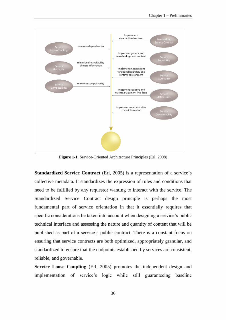
There are a number of principles in the service-orientated paradigm that
provide a means of supporting this theory (Figure 1-1).
Chapter 1 – Preliminaries
36
. Figure 1-1. Service-Oriented Architecture Principles (Erl, 2008)
Standardized Service Contract (Erl, 2005) is a representation of a service’s
collective metadata. It standardizes the expression of rules and conditions that
need to be fulfilled by any requestor wanting to interact with the service. The
Standardized Service Contract design principle is perhaps the most
fundamental part of service orientation in that it essentially requires that
specific considerations be taken into account when designing a service’s public
technical interface and assessing the nature and quantity of content that will be
published as part of a service’s public contract. There is a constant focus on
ensuring that service contracts are both optimized, appropriately granular, and
standardized to ensure that the endpoints established by services are consistent,
reliable, and governable.
Service Loose Coupling (Erl, 2005) promotes the independent design and
implementation of service’s logic while still guaranteeing baseline

Chapter 1 – Preliminaries
37
interoperability with service consumers that have come to rely on the service’s
capabilities. It is a fundamental aspect of services and SOA as a whole.
On a fundamental level, the Service Abstraction (Erl, 2005) principle
emphasizes the need to hide as much of the underlying details of a service as
possible. It directly enables and preserves loosely coupled relationship between
services. Service Abstraction also plays a significant role in the positioning and
design of service compositions. Furthermore, service abstraction allows
services to encapsulate potentially complex processing logic and expose that
logic through a generic and descriptive interface. This is the primary benefit of
service abstraction.
Reuse is strongly advocated within the service-orientation paradigm. The
principle of Service Reusability (Erl, 2005) emphasizes the positioning of
services as enterprise resources with agnostic functional contexts. Numerous
design considerations are raised to ensure that individual service capabilities
are appropriately defined in relation to an agnostic service context, and to
guarantee that they can facilitate the necessary reuse requirements. When a
service encapsulates logic that is useful to more than one service consumer, it
can be considered reusable.
For services to carry out their capabilities consistently and reliably, their
underlying solution logic needs to have a significant degree of control over its
environment and resources. The principle of Service Autonomy (Erl, 2005)
supports the extent to which other design principles can be effectively realized
in real world production environments by fostering design characteristics that
increase a service’s reliability and behavioural predictability. This principle
raises various issues that pertain to the design of service logic as well as the
service’s actual implementation environment. Isolation levels and service
normalization considerations are taken into account to achieve a suitable
measure of autonomy, especially for reusable services that are frequently
shared. This principle applies to a service's underlying logic.
The management of excessive state information (Erl, 2005) can compromise
the availability of a service and undermine its scalability potential. Services are

Chapter 1 – Preliminaries
38
therefore ideally designed to remain stateful only when required. To
successfully design services not to manage state – Service Statelessness
principle – requires the availability of resources surrounding the service to
which state management responsibilities can be delegated.
Designing services so that they are naturally discoverable – service
discoverability principle – regardless of whether a discovery mechanism (such
as a service registry) is used (Erl, 2005), enables an environment where service
logic becomes accessible to new potential service consumers.
The ability to effectively compose services – Service Composability principle
– is a critical requirement for achieving some of the most fundamental goals of
service-oriented computing (Erl, 2005). Services are expected to be capable of
participating as effective composition members.
These SOA principles are beneficial when defining non-functional
requirements for service-oriented enterprise systems (3.3 Non-Functional
Requirements for ESOA Systems).
1.1.2 Service-Oriented Architecture Layers
To implement the service-orientation and support SOA principles identified in
the section above, we need an approach for coordinating and propagating
service-orientation throughout an enterprise. This can be accomplished by
service-oriented architecture layers of abstraction. Each layer can abstract a
specific aspect of solution, addressing one type of the issues identified. This
alleviates us from having to build services that accommodate business,
application, and agility considerations all at once. As a result, to achieve
enterprise-wide loose coupling physically separate layers of services are, in
fact, required. When individual collections of services represent corporate
business logic and technology-specific application logic, each domain of the
enterprise is freed of direct dependencies on the other. This allows the
automated representation of business process logic to evolve independently
from the technology-level application logic responsible for its execution. In

Chapter 1 – Preliminaries
39
other words, this establishes a loosely coupled relationship between business
and application logic.
The three layers (Figure 1-2) of SOA abstraction are identified as follows (Erl,
2005):
The Application Service Layer establishes the ground level foundation that
exists to express technology-specific functionality. Services that reside within
this layer can be referred to simply as application services. Their purpose is to
provide reusable functions related to processing data within new or legacy
application environments. Application services commonly have the following
characteristics (Erl, 2005): they expose functionality within a specific
processing context, draw upon available resources within a given platform, are
solution-agnostic, are generic and reusable, can be used to achieve point-to-
point integration with other application services, are often inconsistent in terms
of the interface granularity they expose, may consist of a mixture of custom-
developed services and third-party services that have been purchased or leased.
Services in the application services layer can fall into the following sub-types
according their purpose (Erl, 2005):
When a separate business service layer exists, there is a strong
motivation to turn all application services into generic utility services.
This way they are implemented in a solution-agnostic manner,
providing reusable operations that can be composed by business
services to fulfil business-centric processing requirements.
Alternatively, if business logic does not reside in a separate layer,
application services may be required to implement service models more
associated with the business service layer.
The application service also can compose other, smaller-grained
application services into a unit of coarse-grained application logic.
Aggregating application services is frequently done to accommodate
integration requirements. Application services that exist solely to enable
integration between systems often are referred to as application

Chapter 1 – Preliminaries
40
integration services or simply integration services. Integration services
are often implemented as controllers.
Wrapper services most often are utilized for integration purposes. They
consist of services that encapsulate “wrap” some or all parts of a legacy
environment to expose legacy functionality to service consumers. The
most frequent form of wrapper service is a service adapter provided by
legacy vendors. This type of out-of-the-box Web service simply
establishes a vendor-defined service interface that expresses an
underlying API to legacy logic.
While application services are responsible for representing technology and
application logic, the Business Service Layer introduces a service concerned
solely with representing business logic, called the business service. This
service is responsible for expressing business logic through service-orientation
and representation of corporate business models. The sole purpose of business
services intended for a separate business service layer is to represent business
logic in the purest form possible. This does not, however, prevent them from
implementing other service models. For example, a business service also can
be classified as a controller service and a utility service. In fact, when
application logic is abstracted into a separate application service layer, it is
more than likely that business services will act as controllers to compose
available application services to execute their business logic. Business service
layer abstraction leads to the creation of two further business service models:
Task-centric business service encapsulates business logic specific to a
task or business process. This type of service is generally required when
business process logic is not centralized as part of an orchestration
layer. Task-centric business services have a limited reuse potential.
Entity-centric business service encapsulates a specific business entity.
Entity-centric services are useful for creating highly reusable and
business process-agnostic services that are composed of an orchestration
layer or a service layer consisting of task-centric business services (or
both).

Chapter 1 – Preliminaries
41
When a separate application service layer exists, these two types of business
services can be positioned to compose application services. Task and entity-
centric business services are explained in more detail in the section below.
The Orchestration Service Layer introduces a parent level of abstraction that
alleviates the need for other services to manage interaction details required to
ensure that service operations are executed in a specific sequence. Within the
orchestration service layer, process (business) services compose other services
that provide specific sets of functions, independent of the business rules and
scenario-specific logic required to execute a process instance.
Orchestration is more valuable than a standard business process, as it allows
directly linking process logic to service interaction within workflow logic. This
combines business process modelling with service-oriented modelling and
design. And, because orchestration languages (such as WS-BPEL) realize
workflow management through a process service model, orchestration brings
the business process into the service layer, positioning it as a master
composition controller. Therefore, all process (business) services are also
controller services by their very nature, as they are required to compose other
services to execute business process logic. Process services also have the
potential for becoming utility services to an extent, if a process, in its entirety,
should be considered reusable. In this case, a process service that enables
orchestration can itself be orchestrated (making it part of a larger
orchestration).

Chapter 1 – Preliminaries
42
Figure 1-2. Three Primary Service Layers (Erl, 2005)
SOA Reference Architecture (SOA-RA, 2011) has nine layers (Figure 1-3)
representing nine key responsibilities that typically emerge in the process of
designing an SOA solution. SOA RA as a whole provides the framework for
the support of all the elements of an SOA, including all the components that
support services and their interactions.
Figure 1-3. SOA Reference Architecture Layers (SOA-RA, 2011)

Chapter 1 – Preliminaries
43
Three layers address the implementation and interface with a service:
The Operational Systems Layer is the layer where all runtime elements of
architecture reside. This layer describes the runtime and deployment
infrastructure: the programs, platforms, application servers, containers, runtime
environments, packaged applications, virtual machines that are on the
hardware and are needed to support the SOA solution.
The Service Component Layer contains software components, each of which
provides the realization for services and their operations. The layer also
contains Functional and Technical Components that facilitate a Service
Component to realize one or more services. Service Components “bind” the
service contract to the implementation of the service in the Operational
Systems Layer. Service Components are hosted in containers which support
the service specifications. In addition to this, the Service Component Layer
manifests the IT conformance with each service contract defined in the
Services Layer. In detail, each Service Component fulfils the following goals:
realizes one or more services, provides an enforcement point for service
realization, enables IT flexibility by strengthening the decoupling in the
system, by hiding volatile implementation details from service consumers.
The Services Layer consists of all the services defined within the SOA. This
layer can be thought of as containing the service descriptions for business
capabilities and services as well as their IT manifestation during design time
together with service contract and descriptions that will be used at runtime.
This layer primarily provides support for services from a design-time
perspective. In particular, from a design-time perspective this includes assets
including service descriptions, contracts, and policies. It defines runtime
capabilities for service deployment, but the runtime instantiation enabling these
capabilities is housed in the Operational Systems Layer. It also provides the
service contract elements that can be created at design time to support
subsequent runtime requirements. These capabilities support the following
main responsibilities of the Services Layer: to identify and define services,
provide a container which houses the services, provide a registry that

Chapter 1 – Preliminaries
44
virtualizes runtime service access, provide a repository to house and maintain
service design-time information.
Three layers in SOA RA that support the consumption of services are as
follows:
The Business Process Layer allows externalization of the business process
flow in a separate layer in the architecture and thus provides a better chance to
rapidly change as the market condition changes.
The Business Process Layer covers process representation and composition,
provides building blocks for aggregating loosely-coupled services. This layer
includes information exchange flow between participants, resources, and
processes. Most of the exchanged information may also include non-structured
and non-transactional messages.
Business processes represent the backbone of the flow of a business. The
dynamic side of business architecture is realized through business processes.
With service-orientation, a process can be realized by service compositions
employing orchestration or a choreography.
In particular, compositions of services exposed in the Services Layer are
defined in this layer: atomic services are composed into a set of composite
services using a service composition engine. A composition of services can be
implemented as choreography of services or an orchestration of the underlying
service elements.
In more detail, the Business Process Layer performs three-dimensional
process-level handling: top-down, bottom-up, and horizontal. From the top-
down direction, this layer provides facilities to decompose business
requirements into tasks comprising activity flows, each being realized by
existing business processes, services, and service components. From the
bottom-up direction, the layer provides facilities to compose existing business
processes, services, and service components into new business processes. From
the horizontal direction, the layer provides services-oriented collaboration
control between business processes, services, and service components.

Chapter 1 – Preliminaries
45
The Consumer Layer is the point where consumers interact with SOA. It
enables an SOA to support a client-independent set of functionality, which is
separately consumed and rendered through one or more channels (client
platforms and devices). In fact the Consumer Layer is the entry point for all
external consumers, external to SOA. This can be other systems, other SOAs,
cloud service consumers, human users etc.
The Integration Layer is a key enabler for an SOA as it provides the
capability to mediate, which includes transformation, routing and protocol
conversion to transport service requests from the service consumer to the
correct service provider. This layer enables the service consumer to connect to
the correct service provider through the introduction of a reliable set of
capabilities. The integration can start with modest point-to-point capabilities
for tightly-coupled end-points and cover the spectrum to a set of much more
intelligent routing, protocol conversion, and other transformation mechanisms
often described as, but not limited to, an Enterprise Service Bus (ESB). WSDL
specifies a binding, which implies location where a service is provided, and is
one of the mechanisms to define a service contract. An ESB, on the other hand,
provides a location-independent mechanism for integration, and service
substitution or virtualization.
Four layers (including Integration layer) support cross-cutting concerns of a
more supporting (non-functional) nature:
The Information Layer is responsible for manifesting a unified representation
of the information aspect of an organization as provided by its IT services,
applications, and systems enabling business needs and processes and aligned
with the business vocabulary – glossary and terms. This layer includes
information architecture, business analytics and intelligence. Furthermore, an
information virtualization and information service capability typically involves
the ability to retrieve data from different sources, transform it into a common
format, and expose it to consumers using different protocols and formats.

Chapter 1 – Preliminaries
46
The Quality of Service Layer provides solution QoS management of various
aspects, such as availability, reliability, security, as well as mechanisms to
support, track, monitor, and manage solution QoS control.
The Quality of Service Layer provides the service and SOA solution lifecycle
processes with the capabilities required to ensure that the defined policies,
Non-Functional Requirements (NFRs), and governance regimens are adhered
to. This layer supports the monitoring and capturing service and solution
metrics in an operational sense and signalling non-compliance with NFRs
relating to the salient service qualities and policies associated with each SOA
layer. Service metrics are captured and connected with individual services to
allow service consumers to evaluate service performance, creating increased
service trust levels. In the SOA RA policies, business rules, and the NFRs and
policies for the SOA solution are defined and captured in the Governance
Layer but are monitored and enforced in the Quality of Service Layer.
Responses (dispensations and appeals) to non-compliance and exceptions are
defined by the Governance Layer as well.
The Governance Layer ensures that the services and SOA solutions within an
organization adhere to the defined policies, guidelines and standards that are
defined as objectives, strategies and regulations applied in the organization and
that the SOA solutions are providing the desired business value.
The Governance Layer includes both SOA governance (governance of
processes for policy definition, management, and enforcement) as well as
service governance (service lifecycle). This covers the entire lifecycle of the
services and SOA solutions (i.e., both design and runtime) as well as the
portfolio management of both the services and SOA solutions managing all
aspects of services and SOA solutions (e.g., Service-Level Agreement (SLA),
capacity and performance, security and monitoring).
This layer can be applied to all the other layers in the SOA RA. From a Quality
of Service and management perspective, it is well connected with the Quality
of Service Layer. From a service lifecycle and design-time perspective, it is

Chapter 1 – Preliminaries
47
connected with the Services Layer. From an SOA solution lifecycle
perspective, it is connected to the Business Process Layer.
The value of this layer is to ensure that the mechanisms are in place to
organize, define, monitor, and implement governance from an enterprise
architecture and solution architecture view.
To sum up, SOA RA depicts an SOA as a set of logical layers. One layer does
not solely depend upon the layer below it and is thus named a partially-layered
architecture: a consumer can access the Business Process Layer or the Services
Layer directly, but not beyond the constraints of an SOA architectural style.
For example, a given SOA solution may exclude a Business Process Layer and
have the Consumer Layer interacting directly with the Services Layer. Such a
solution would not benefit from the business value proposition associated with
the Business Process Layer; however, that value could be achieved at a later
stage by adding the layer.
SOA RA illustrates the multiple separations of concern in the nine layers of the
SOA RA. The SOA RA does not assume that the provider and the consumer
are in one organization, and supports both SOA within the enterprise (ESOA)
as well as across multiple enterprises. The Services Layer is the decoupling
layer between consumer and provider.
The lower layers (Services Layer, Service Component Layer, and Operational
Systems Layer) are concerns for the provider and the upper ones (Services
Layer, Business Process Layer, and Consumer Layer) are concerns for the
consumer. The main point of the provider and consumer separation is that there
is value in decoupling one from the other along the lines of business
relationship. Organizations which may have different lines of business use this
architectural style, customizing it for their own needs and integrating and
interacting among themselves.
Five horizontal layers are more functional in nature and relate to the
functionality of the SOA solution. The supporting layers are supportive of
cross-cutting concerns that span the functional layers but are clustered around

Chapter 1 – Preliminaries
48
independent notions themselves as cross-cutting concerns of the SOA
architectural style.
Later, in Chapter 3.4.1 Composition of ESOA Viewpoints, we will see that our
proposed viewpoints for service-oriented enterprise systems non-functional
requirements capturing and analysis are based on SOA layers described in this
section.
1.1.3 Service and Service Type
Services are the most essential units of service-oriented architecture, due the
name of the architecture. Services are abstractions of existing application
capabilities (encapsulated business components) that are aligned with the
business functions of an enterprise. Service is therefore the implementation of
such business functionality that it is accessible through a well-defined
interface. Services are exchanged between service consumers and service
providers over the Enterprise Service Bus (ESB) through interfaces.
When building various types of services, it becomes evident that they can be
categorized depending on the type of logic they encapsulate, the extent of reuse
potential this logic has, and how this logic relates to existing domains within
the enterprise. As a result, there are three common classifications that represent
the primary service types depicted in Figure 1-4 (Erl, 2008):
Entity Services. Every enterprise at some point in time has to define its
business entities. Examples of business entities include customer,
employee, invoice etc. It is considered to be a highly reusable service
because it is agnostic to most parent business processes. As a result, a
single entity service can be leveraged to automate multiple parent
business processes. Entity services are also known as entity centric
business services or business entity services.
Task Services. This type of service tends to have less reuse potential
and is generally positioned as the controller of a composition
responsible for composing other services. If we have process logic that
spans multiple entity domains and does not fit cleanly within a

Chapter 1 – Preliminaries
49
functional context associated with a business entity then this would
typically constitute a parent process in that it consists of processing
logic that needs to coordinate the involvement of multiple services.
Services with a functional context defined by a parent business process
or task can be developed as standalone Web services or components or
they may represent a business process definition hosted within an
orchestration platform. This type of service is referred to as the
orchestrated task service. Task services are also known as task-centric
business services or business process services. Orchestrated task
services are also known as process services, business process services
or orchestration services.
Utility Services. Each of the previously described service models has a
very clear focus on representing business logic. However, there is not
always a need to associate logic with a business model or process. In
fact, it can be highly beneficial to deliberately establish a functional
context that is non-business-centric. This essentially results in a distinct,
technology-oriented service layer. The utility service accomplishes this.
It is dedicated to providing reusable, cross-cutting utility functionality,
such as event logging, notification, and exception handling. Utility
services are also known as application services, infrastructure services,
or technology services.
Figure 1-4. Service Types by Erl (Erl, 2008)

Chapter 1 – Preliminaries
50
Later, in Chapter 4.1 Definition of ESOA Viewpoints, we will see that our
proposed Business Process and Services viewpoints orchestrate and define
Entity and Task services described in this chapter.
1.2. Enterprise Service-Oriented Architecture
One of the sub-styles of SOA is an Enterprise SOA – ESOA (Figure 1-5), to
use the term coined by the SAP Corporation (SAP, 2008). ESOA provides
guidelines on how to develop and to use service-oriented applications in
Enterprise Systems (a.k.a. Systems of Systems). It is business-driven, that is, it
must support an enterprise’s business strategy and objectives. This means that
business processes in ESOA must be designed keeping this goal in mind. On
the other hand, business processes should be translated into abstracted and
normalized Enterprise Business Systems – EBSs drawing on global data types.
Normalization means that EBS should be designed with the intent to avoid
functional overlaps and to reduce the redundancy (i.e. similar or duplicate
bodies of service logic). Global data types are enterprise-wide defined data
types based on international standards (Sambeth, 2006). To simplify
enterprise-wide service integration and communication, ESOA provides
typically one additional architectural element referred to as enterprise service
bus. According to (Bichler & Lin, 2006), ESOA allows an enterprise to use
plug-and-play interoperability to compose business processes and integrate
different information systems on the fly to enable ad hoc cooperation between
new partners. It creates business services networks, also known as service
supply chains that raise many new questions about how to foster collaboration
and orchestrate processes among partners (Bichler & Lin, 2006). So ESOA in
many aspects differs from SOA. Although some service providers in ESOA
can reside outside an enterprise and, vice versa, some service consumers also
can reside outside the enterprise, they must keep up the enterprise’s standards
and all are designed keeping these standards in mind. In this sense the ESOA
system is operating rather in a less open environment than ordinary SOA.

Chapter 1 – Preliminaries
51
Figure 1-5. Structure of Enterprise Service-Oriented Architecture (based on Minoli, 2008)
1.3. User Requirement Standard Notation Languages
User Requirements Notation – URN intended for the elicitation, analysis,
specification, and validation of requirements. URN combines modelling
concepts and notations for goals (mainly for non-functional requirements and
quality attributes) and scenarios (mainly for operational requirements,
functional requirements, and performance and architectural reasoning). The
goal sub-notation is called Goal-oriented Requirements Language – GRL

Chapter 1 – Preliminaries
52
(Figure 1-6) and the scenario sub-notation is called Use Case Map – UCM
(Figure 1-7).
URN helps to describe and communicate requirements, and to develop
reasoning about them. The main applications areas include telecommunications
systems, services, and business processes, but URN is generally suitable for
describing most types of reactive systems and information systems (ITU-T,
2008). The range of applications is from business goals and requirements
description to a high-level system design and architecture. URN allows
software and requirements engineers to discover and specify requirements for a
proposed system or an evolving system, and analyse such requirements for
correctness and completeness.
Goal-oriented Requirement Language – GRL is a language for supporting
goal-oriented modelling and reasoning about requirements, especially non-
functional requirements and quality attributes. It provides constructs for
expressing various types of concepts that appear during the requirement
process. GRL has its roots in two widespread goal-oriented modelling
languages: i* (Yu, 2009) and the NFR Framework (Chung et al, 2000). Major
benefits of GRL over other popular notations include the integration of GRL
with a scenario notation and a clear separation of GRL model elements from
their graphical representation, enabling a scalable and consistent representation
of multiple views/diagrams of the same goal model.
There are three main categories of concepts in GRL: actors, intentional
elements, and links (Figure 1-6). The intentional elements in GRL are goals,
soft goals, tasks, resources, and beliefs (Figure 1-6). They are intentional
because they are used for models that allow system stakeholders to answer
questions such as why particular behaviours, informational and structural
aspects were chosen to be included in the system requirements, what
alternatives were considered, what criteria were used to deliberate among
alternative options, and what the reasons were for choosing one alternative
over the other. Actors are holders of intentions; they are the active entities in
the system or its environment (e.g., stakeholders or other systems) who want

Chapter 1 – Preliminaries
53
goals to be achieved, tasks to be performed, resources to be available, and soft
goals to be satisfied. Links are used to connect isolated elements in the
requirement model. Different types of links depict different structural and
intentional relationships (including decompositions, contributions, and
dependencies).
This kind of modelling is different from the detailed specification of “what” is
to be done. Here the modeller is primarily concerned with exposing “why”
certain choices of behaviour and/or structure were made or constraints
introduced. The modeller is not yet interested in the operational details of
processes or system requirements, or component interactions. Omitting these
kinds of details during early development and standardization phases allows us
taking a higher level (sometimes called a strategic stance) towards modelling
the current or the future standard or software system and its embedding
environment. Modelling and answering “why” questions leads us considering
the opportunities stakeholders seek out and/or vulnerabilities they try to avoid
within their environment by utilising capabilities of the software system and/or
other stakeholders, by trying to rely upon and/or assign capabilities and by
introducing constraints on how those capabilities ought to be performed.
Figure 1-6. GRL notation (ITU-T, 2008)
Chapter 1 – Preliminaries
54
Use Case Map (UCM) specifications employ scenario paths to illustrate causal
relationships among responsibilities (ITU-T, 2008). Furthermore, UCMs
provide an integrated view of behaviour and structure by allowing the
superimposition of scenario paths on a structure of abstract components. The
combination of behaviour and structure enables architectural reasoning after
which UCM specifications may be refined into more detailed scenario models
such as UML sequence diagrams, UML state chart diagrams and finally into
concrete implementations. Validation, verification, performance analysis,
interaction detection, and test generation can be performed at all stages. Thus,
the UCM notation enables a seamless transition from the informal to the formal
by bridging the modelling gap between goal models and natural language
requirements (e.g. use cases) and design in an explicit and visual way. The
UCM notation allows the modeller to delay the specification of component
states and messages and even, if desired, of concrete components to later, more
appropriate, stages of the development process. The goal of the UCM notation
is to provide the right degree of formality at the right time in the development
process.
UCM specifications identify input sources and output sinks as well as describe
the required inputs and outputs of a scenario. UCM specifications also
integrate many scenarios or related use cases in a map-like diagram. Scenarios
can be structured and integrated incrementally. This enables reasoning about
and the detection of potential undesirable interactions of scenarios and
components. Furthermore, the dynamic (run-time) refinement capabilities of
the UCM notation allow of the specification of (run-time) policies and of the
specification of loosely coupled systems where functionality is decided at
runtime through negotiation between components or compliance with high-
level goals. UCM scenarios can be integrated together, yet individual scenarios
are tractable through scenario definitions based on a simple data model. UCMs
treat scenario paths as first class model entities and therefore build the
foundation to more formally facilitate the reusability of scenarios and
behavioural patterns across a wide range of architectures.

Chapter 1 – Preliminaries
55
The UCM notation (Figure 1-7) is a specification language intended for
modellers as well as non-specialists because of its visual, simple, and intuitive
nature but at the same time it aims to provide sufficient rigorousness for
developers or tools and contracts.
Most of the characteristics of excellent requirements such as verifiable,
complete, consistent, unambiguous, understandable, modifiable, and traceable
can be supported by UCMs. Others such as prioritized and annotated are easily
incorporated.
Figure 1-7. UCM notation (ITU-T, 2008)
The examples of GRL and UCM diagrams can be found in Chapter 4.2.2
Modelling of User Concerns and NFRs in Consumer Viewpoint using GRL
and UCM; Chapter 4.3.2 Modelling of User Concerns and NRFs in Business
Process Viewpoint Chapter 4.4.2 Modelling of User Concerns and NFRs in
Customer and Business Process Viewpoints using GRL and UCM .

Chapter 2 – State of the Art
56
Chapter 2
State of the Art
The chapter presents the state-of-the-art Service-Oriented Requirement
Engineering and all other interrelated enterprise and service-oriented
architecture areas that could be used for non-functional requirements
conflicts resolution in ESOA systems. Section 1 analyses the current state
of Service-Oriented Requirement Engineering, highlights the issues and
challenges of SORE in comparison to traditional RE and CBSD RE,
outlines the key features of service-oriented requirement engineering,
describes few classical RE process models together with service-oriented
RE process models. Section 2 analyses Service-Oriented Architecture
systems development methodologies and performs their analysis and design
phases’ comparison. Section 3 analyses the problematics of capturing non-
functional requirements for ESOA systems using viewpoints. Section 4
analyses Enterprise Architecture Frameworks and Standards by taking the
biggest attention to the sets of views/viewpoints with the aim to grasp an
idea about the possible set of viewpoints for ESOA.
2.1. Service-Oriented Requirement Engineering
Service-Oriented Requirement Engineering (SORE) like traditional
requirement engineering, concerns with specification and analysis of system
requirements and constraints, but its focus is on the identification of services
and workflows used to modelling applications and on their reuse. Service-
Oriented Software Engineering (SOSE) is a relatively new and still rapidly
growing research and development area. This discipline emerged in the last
decade of previous century (Arsanjani, 1999; Layzell, et al, 2000), as a
response to the challenges of integration of heterogeneous applications,
including legacy ones, cross-platform interoperability and bridging the gap
between business models and software architectures. In its initial stages SORE

Chapter 2 – State of the Art
57
was concerned mostly with the service-oriented software process considering it
as an extension and improvement of the Rational Unified Process (Rational
Software, 1998) or IBM’s Global Service’s Method (Arsanjani, 2001). SORE
as an integral part of SOSE emerged in the first quinquennium of the 21st
century. First publications on this topic discussed the nature of this discipline,
its differences between SORE and traditional RE, the structure of service-
oriented requirements lifecycle, and possible approaches to address the
identification and handling of functional and non-functional requirements for
service-oriented systems (Van Eck & Wieringa, 2003; Trienekens et al, 2004).
A number of publications that gave an overview of the state of the art of this
discipline, highlighted open problems and challenges, and aimed to build the
roadmap for further research was published from this time up to date (Bano, et
al, 2010; Flores, et al, 2010; Flores et al, 2009).
In addition to this, several Service-Oriented System Development
methodologies and approaches such as (Svanidzaitė, 2014a): IBM RUP/SOMA
(chapter 2.2.1 IBM RUP/SOMA), SOAF (chapter 2.2.4 Service-Oriented
Architecture Framework – SOAF), SOUP (chapter 2.2.5 Service-Oriented
Unified Process – SOUP), methodology by Tomas Erl (chapter 2.2.2 Service-
Oriented Analysis and Design Methodology by Thomas Erl) and methodology
by Michael Papazoglou (chapter 2.2.3 Service-Oriented Design and
Development Methodology by Papazoglou) have been proposed to ensure
successful service-oriented systems development by providing process
guidance and proven best practices from already accomplished SOA projects.
SOA development lifecycle in these methodologies is divided into nine phases:
Service-oriented planning/inception, Service-oriented analysis, Service-
oriented design, Service Construction, Service Testing, Service Provisioning,
Service Deployment, Service Execution and Service Monitoring. Although
these methodologies help to structure Service-Oriented systems development
processes, they are not aimed at defining SORE process and do not provide any
approach to requirement conflicts resolution.

Chapter 2 – State of the Art
58
Furthermore, several architecture frameworks, architecture reference models
emerged to ensure successful service-oriented architecture development such
as - OASIS Reference Architecture Foundation for SOA (SOA-RAF) that
describes (SOA-RAF, 2012) the foundation upon which Service-Oriented
Architectures can be built. It follows the concepts and relationships defined in
the OASIS Reference Model for Service Oriented Architecture (SOA-RM,
2006) (chapter 2.4.4 OASIS Reference Architecture Foundation for SOA –
OASIS SOA RAF. Moreover, there are SOA standards that are still under
development such as IEEE P1723 Standard for a Service-Oriented Architecture
(SOA) Reference Architecture (chapter 2.4.3 IEEE P1723 Standard for
Service-Oriented Architecture (SOA) Reference Architecture). There are more
architecture frameworks such as the Zachman Enterprise Architecture
Framework (chapter 2.4.5 Zachman Enterprise Architecture Framework), The
Open Group Architecture Framework – TOGAF (chapter 2.4.6 Open Group
Architecture Framework – TOGAF), Extended Enterprise Architecture
Framework (chapter 2.4.7 Extended Enterprise Architecture Framework),
Department of Defence Architecture Framework – DoDAF (chapter 2.4.8
Department of Defence Architecture Framework – DoDAF), Kruchten’s
“4+1”/RUP’s 4 + 1 View Model (chapter 2.4.9 Kruchten’s “4+1”/RUP’s 4 + 1
View Model), Siemens 4 views method (chapter 2.4.10 Siemens 4 views
method), Reference Model for Open Distributed Processing (RM-ODP)
(chapter 2.4.11 Reference Model for Open Distributed Processing) which can
be of a great help for Service-Oriented Requirement Engineering. As a result,
further research is required.
Service-oriented architecture has become new reference architecture for
distributed computing as it allows rapid and low-cost application development
through service composition. Requirement Engineering (RE) is considered a
critical software engineering process that performed in a structured and well-
defined manner should result in a set of complete, unambiguous, measurable,
traceable, documented requirements that must be realized by services
composing a service-oriented system. For traditional computing paradigms

Chapter 2 – State of the Art
59
(e.g. object-oriented and component-based) several stable RE processes are
available. As service-oriented computing is a new software engineering
paradigm, few solutions to RE process structuration have been proposed (2.1.3
Service-Oriented RE Process and Models) but none of them has either gained
acknowledgment or has been widely adopted for developing successful SOA
projects.
SOA is considered of a high value for being deployed in organizations.
However, for this to happen, the Service-Oriented Software System must be
engineered through a system development life cycle SDLC (Flores et al, 2010;
Flores, et al, 2009). While in classic RE for object-oriented and component-
based software development paradigms there are stable RE processes and
techniques, in the service-oriented software paradigm a clear, stable and
systematic RE process is still under research (Flores, et al, 2010; Flores, et al,
2009). The need for service-oriented RE processes has been reported by
diverse authors in (Flores, et al, 2010; Barker, 2004; Lamsweerde, 2000;
Trienekens, et al, 2004) outlining the problems such as:
reduced utilization of service performance metrics,
unclear, incomplete, negative or static service specifications,
significant and yet unexplored socio-technical issues experienced in
negotiating conflicting customer and provider service requirements.
The first step to make advance in these issues is to highlight the main problems
and challenges that SORE faces today, outline the main differences from
traditional RE and key features of SORE.
Research by (Bano, et al., 2010) suggests deriving and categorizing main SORE
problems by comparing the issues and challenges faced in traditional RE and in
CBSD. Traditional RE faces such challenges as Issues regarding stakeholders
when each stakeholder has different needs of supposed system functionality,
capturing, modelling and analysing functional and non-functional requirements,
ensuring reuse of requirement models and formal representation of
requirements from natural language when a need to decide how requirements
will be captured analysed and documented arises, also Requirement

Chapter 2 – State of the Art
60
change/evolution and Conflict resolution in requirements – these issues are
faced during Requirement Management and Requirement Change Management
activities. The Component-based Software Development (CBSD) lifecycle is
different from the traditional meaning that the classical RE process cannot be
applied and some new methods and techniques are required. As a result,
Component Based Software Development RE faces such problems as:
Non-existence of RE process, resulting in huge challenges of searching
and selection of components;
Non-existence of sophisticated non-functional requirements elicitation
techniques that are required as NFRs play an important role in quality
comparison among multiple components that provide the same
functionality;
Non-applicability of traditional RE approaches because of:
o Specifications of existing components should also be considered
when eliciting new system’s requirements;
o Systematic evaluation and testing of components against user
requirements is needed;
o As components are black box in their nature, the source code is
not provided resulting in the inflexibility for their customization
and leading to the failure of system at the time of integration;
o Components’ versioning can cause problems as a new version
may not match the existing system requirements.
The issues and challenges in service-oriented RE are to some extent inherited
from CBSD as well as traditional RE. The following problems can be outlined:
Non-existence of RE techniques for Service Discovery issues. Service
Discovery is one of the most important features of the service-oriented
paradigm so effective mechanisms are required to locate a correct
service according to user requirements;

Chapter 2 – State of the Art
61
Non-existence of a structured, iterative RE process that is required to
refine the requirement specifications and ensure requirement traceability
and change management;
Non-existence of RE techniques that should provide capability to
redesign and redeploy the composed service when user needs change
over time is necessary;
Non-existence of RE techniques that should provide a bridge between the
semantic gaps, which are inevitable when services are brought together
from hybrid environments is required;
Service knowledgement issues as the non-existence of RE techniques that
should provide capability to manage the knowledge of a group/cluster of
services with similar functionality is mandatory.
The issues identified above can be grouped into four categories:
1. Service Specification issues deals with requirements’ elicitation and
documentation for a service-oriented software system, composing a
Service-oriented Software System from services that will fulfil these
requirements.
2. Service Discovery issues deals with the searching for services after their
specifications are prepared and finding out which of the services actually
meet the functional and non-functional requirements.
3. Service Knowledge Management issues deals with the knowledge
management of service compositions functionality that would help
service specification and discovery.
4. Service Composition issues deals with the investigation issues deciding
whether the integrated service-oriented systems will meet the original
requirements defined for each service separately.
The second step to advance SORE process structuration is to analyse its key
features and technical challenges. Research by (Tsai, et al, 2007) provides a
deep overview of SORE key features and starts analysis from stating that not
only can services be published and discovered, but also other artefacts such as:

Chapter 2 – State of the Art
62
workflows or collaboration templates specifying the execution sequence
of a workflow with multiple services,
application templates specifying the entire applications with their
workflows and services,
data and associated data schema, such as messages produced during
SOA execution,
policies that are used to enforce SOA execution,
test scripts that can be used by customers, producers and brokers to
verify SOA application,
interfaces that are used and linked at runtime to facilitate dynamic SOA
application with changeable interfaces.
Service-oriented RE is considered from three points of views:
1. producer centric when producers publish services and customers search
and discover their needed services,
2. consumer centric when consumers publish their needs and let the
providers to supply one of the above mentioned reusable artefacts,
3. broker centric when brokers publish test scripts, specifications and let
the producers supply services/workflows and consumers discover the
services and use test scripts for testing.
In addition to this, SORE has the following major features (Tsai, et al, 2007):
is reusability-oriented and cumulative in a way that SORE can reuse not
only SORE reusable artefacts developed for the same project, but also
artefacts developed and published in other projects. Not only can SORE
artefacts be reused, but also SORE processes can be reused as well.
SORE is domain specific. An important feature of SORE is that it
should use domain-specific items including ontology, services,
workflows, collaboration templates, application templates, user
interfaces, and policies. For example, a banking application may use
reusable banking-related ontology, services, and workflows.

Chapter 2 – State of the Art
63
SORE employs framework-oriented analysis. SORE reusable artefacts
should be organized in different frameworks and SORE should become
framework oriented with the aim to find artefacts that can be reused to
fulfil the requirements.
Model-driven development. SORE should take model-driven approach
when, firstly, a foundation model for application is created and later
needed services based on model specified are invented.
Evaluation-based development. Only pre-selected services can be used
at runtime and all the pre-selected services/workflows must be
thoroughly pre-evaluated before they can be placed in a service or
workflow pool.
User-centric analysis and specification. SORE can play two roles here:
one is to help these end users to identify their application requirements,
possibly using a set of visual tools, and the other is to identify tool
features that help end users to rapidly develop their applications.
Policy-based computing. Policies need to be specified, analysed,
enforced, and evaluated, and thus it has a lifecycle model that is parallel
with the software development. Policy specifications are usually
executable, however, policy evaluation and execution is different from
software evaluation and execution because policies need to be evaluated
together with the functional software to be enforced.
Furthermore, SORE also introduces some technical challenges such as
(Tsai, et al, 2007):
Software-Oriented Ontology – ontology in SORE provides service-
oriented modelling and analysis, facilitates code generation, and
promotes software reusability. The main use of ontology in SORE is to
construct a domain model that is capable of developing SOA
applications rapidly in a model-driven SOA lifecycle model.
Service-Oriented Simulation using a service-oriented simulation
framework. It is possible to simulate the SOA application according to

Chapter 2 – State of the Art
64
its specification, possibly with many existing and reusable services and
workflows.
Model-based Development. One key issue for SOA model-based
development is the development of modelling language suitable for rapid
SOA application development. In such a rapid application lifecycle
model many tasks should be performed based on the model specified.
Specifically, various static and dynamic analyses such as completeness
and consistency and simulation should be based on the model developed;
design or assembly should also be based on the model developed with
various ontology systems and service brokers. A code should be
automatically generated based on the assembled model with reusable
services and workflows; test scripts generated based on the assembled
model and reusable test scripts associated with services and workflows.
Policies identified and specified together with a functional model using
the same modelling language. In this way, as the software needs change,
the model will be updated, reanalysed, and re-assembled, and the code
will be regenerated and re-tested and re-evaluated.
Non-functional Requirements. A SOA system usually consists of many
reusable services and workflows, and non-functional requirements need
to be applied across the software including those services and
workflows that are reused. It is necessary to develop a mechanism to
specify and analyse these non-functional requirements for SORE.
To sum up, comparing with traditional requirement engineering, the distinction
lies on modelling techniques, a model-based development process, and runtime
behaviours including publishing, discovery, composition, monitoring and
enforcement of services.
2.1.1. An Overview of Classic and Service-Oriented Requirement
Engineering: The Process and Techniques
Software Requirements Engineering is a process responsible for requirements’
elicitation, analysis and documentation with the aim to create a cost-effective

Chapter 2 – State of the Art
65
solution to practical problems by applying scientific knowledge (Shaw, 1990).
It is considered to be a critical software engineering process that when
performed in a structured and well-defined manner should result in a set of
complete, unambiguous measurable, traceable, documented requirements that
must be realized by a software system. RE is the most important activity in the
System Development Life Cycle (SDLC) as the system is only as good as its
requirements. The requirements’ engineering phase of the SDLC is comprised
of the following activities: Requirements Elicitation, Requirements Analysis,
Requirements Verification, Requirements Specification, and Requirements
Management. All these activities should be performed during the software
Requirements engineering process. Requirement engineering process models
structure the process and provide roadmaps how to perform these activities. RE
models depend on several attributes such as the type of application that is
being developed, software development and acquisition process that is being
used, the size and culture of the companies involved. Next two sections discuss
RE models and approach to the classic and service-oriented RE, and highlight
their benefits and shortcomings.
2.1.2. Classic RE Process and Models
Classic RE models vary from the simplest such as an Input/Output of
Requirements Engineering Process (Shams-Ul-Arif, et al, 2009–2010; Kotonya
& Sommervile, 1998) that suggest taking five work products: (1) Existing
System Information, (2) Stakeholder Needs, (3) Organizational Standards, (4)
Regulations and (5) Domain Information as inputs apply a Requirement
Engineering Process to them and produce three work products: (1) Agreed
Requirements, (2) System Specification and (3) System Models as an output.
This is a general sort of requirement engineering process and is flexible to be
adapted by any organization to any project through defining organizational
applied standards and regulations (Shams-Ul-Arif, et al, 2009–2010). This RE
model is further refined to more advanced RE models such as: Linear
Requirements Engineering Process Model (Kotonya & Sommervile, 1998;

Chapter 2 – State of the Art
66
Shams-Ul-Arif, et al, 2009-2010), Linear Iterative Requirement Engineering
Process Model (Kotonya & Sommervile, 1998; Shams-Ul-Arif, et al, 2009–
2010), Iterative Requirement Engineering Process Model (Kotonya &
Sommervile, 1998; Shams-Ul-Arif, et al, 2009–2010) that suggests three
iteratively accomplished activities: (1) Elicitation, (2) Specification and (3)
Validation. Requirements engineering activities in this model are performed in
multiple iterations and hence it is more suitable for the development of software
systems that should be launched version by version into the market. Spiral
Requirement Engineering Process Model (Kotonya & Sommervile, 1998;
Shams-Ul-Arif, et al, 2009-2010) suggests performing RE process in spirals and
each spiral represents a complete version of requirements on which the system
has to be developed.
J.D. Arthur, M. K. Gröner (Arthur & Gröner, 2005) suggest Requirements
Generation Model – RGM (Figure 2-1) – a structured approach to capturing
requirements which is based on two components:
framework that structures and controls RE activities and introduces two
phases – Indoctrination and Requirements Capturing. The indoctrination
phase aims to familiarize the customer with the RGM, introduce the
requirements’ engineer to the customer’s domain, define and set up tasks
and responsibilities needed during the requirements capturing phase.
Requirements Capturing phase consists of these three sub-phases:
Preparation – to prepare for requirement elicitation meetings,
Requirements Elicitation – to conduct requirement elicitation meetings,
and Review – to discuss and analyse requirements elicited.
monitoring methodology that ensures that all requirements activities
follow proper procedures.

Chapter 2 – State of the Art
67
Figure 2-1. Requirements’ Generation Model – RGM (Arthur and Gröner, 2005)
The classic RE process performed by us and models analysis is not an extensive
one as our purpose it not to review all existing approaches, but just to highlight
the ones that are most popular and include some novelties.
2.1.3. Service-Oriented RE Process and Models
As we have seen from the previous section, Service-oriented RE (SORE)
inherits issues from traditional RE and CBSD RE and faces new challenges
which can be broadly grouped into service specification, knowledge
management, discovery and composition issues. A few SORE models have
already been proposed to solve them.
Systematic Service-Oriented Requirements Engineering (SORE) Process
(Flores et al, 2009) is aimed mainly to solve service specification issues. It is
based on a three-fold concept of service:
1. as a high-level business service – a developed software system should
provide capability to realize business processes that support business
strategy and business goals;
2. as an operational business service – a developed software system
should be aligned with each activity in business processes that it finally
will support;

Chapter 2 – State of the Art
68
3. as an IT service level – high-level business requirements should be
translated into IT low-level requirements and operational
specifications.
A systematic SORE process (Figure 2-2) is defined as consisting of three
phases (Flores, et al, 2010):
1. Business Process Modelling Phase where business goals and the
business processes that support those goals are identified by making a
high-level model of the business processes.
2. Flow-Down Phase concerns with each business process identified in the
phase above, detecting, understanding and analysing each activity
needed to successfully execute the business process flowing it down
until the business process architecture is discovered.
3. Formal Requirements Specification Phase. Requirements that the
developed service-oriented software system needs to successfully
satisfy the business process are formally established by negotiating and
elaborating Service Level Agreements (SLAs) and translating them in
Operational Level Agreements (OLAs).
Figure 2-2. Systematic SORE Process IDEF0 Detailed Diagram (Flores, et al, 2010)

Chapter 2 – State of the Art
69
Another solution to structure SORE process was reported by (Flores, et al,
2009; Flores, et al, 2008). According them, the SORE process can be
conducted through the following six RE activities:
1. Contextual Analysis. Consideration of the environmental influences
(economic, political, business goals, and legal) which could affect a
successful software system development.
2. Elicitation. The stakeholders, their needs and problems, as well as their
willingness to provide information are elicited.
3. Analysis. The structure of requirements is identified, finding out their
interrelationships.
4. Modelling and Representation. A requirements’ engineer models each
requirement in an agreed and readable way that these requirements
could be clearly understood.
5. Communication and Negotiation. A requirement’s engineer introduces
every identified requirement to each stakeholder in order to avoid
mistakes or misunderstandings.
6. Validation and Final Specification. All identified requirements are
validated, and if there is no change, a requirement’s engineer elaborates
the final requirement specifications.
7. Change Management. Activity is performed after each of the above
mentioned activity in order to record and track every change realized. A
history of the RE process is available for auditing and continuous
improvement issues.
This approach also concerns mainly service specification issues. In addition to
this, these two proposed SORE approaches lack particularity. So, as a result,
further research is needed that would cover service specification issues and the
other ones named above as well.

Chapter 2 – State of the Art
70
2.2. Overview of Service-Oriented Software Systems’
Development Methodologies and Approaches
A number of SOA methodologies such as IBM RUP/SOMA, SOAF, SOUP,
service-oriented analysis and design methodology by Thomas Erl and service-
oriented design and development methodology by Papazoglou have been
proposed to ensure successful SOA development by providing process
guidance and the best proven practices from already accomplished SOA
projects. The SOA development lifecycle in these methodologies can be
divided into these phases: Service-oriented planning/inception, Service-
oriented analysis, Service-oriented design, Service Construction, Service
Testing, Service Provisioning, Service Deployment, Service Execution and
Service Monitoring. The first two or three phases are the most important ones
because the success of SOA development mainly depends on them.
Technology and standards, such as Business Process Management – BPM,
Business Process Execution Language – BPEL, Web Service Definition
Language – WSDL, Enterprise Architecture – EA, Object-Oriented Analysis
and Design – OOAD are important to develop SOA, but it has been widely
recognized that they are not sufficient on their own. Just by applying a Web
service layer on top of legacy applications or components does not guarantee
true SOA properties, such as business alignment, flexibility, loose coupling,
and reusability. Instead, a systematic and comprehensive SOA analysis and
design methodology is required (Papazoglou, 2006). A number of SOA
methodology surveys have already been performed but they treat them from a
general point of view without providing any in-depth analysis of the properties
of these methodologies aiming at SOA analysis and design phases. We
performed research that contributes to outlining the drawbacks and benefits of
proposed SOA methodologies and focuses on SOA analysis and design phases
by providing in-depth analysis and a comparison according to characteristics
specified (chapter 2.2.6 Characteristics of SOA Methodologies Analysis and
Design Phases). In addition to this, the analysis also helped us to propose the

Chapter 2 – State of the Art
71
structure of SORE process described in the next chapter. Furthermore, the
SOA methodologies discussed below were used to define SOA quality
attributes.
2.2.1. IBM RUP/SOMA
IBM RUP/SOMA (IBM RUP/SOMA; Ramollari, et al, 2007) is an integrated
methodology developed by IBM with an aim to bring unique aspects of
Service-oriented Modelling and Architecture – SOMA to RUP. However,
because SOMA is a proprietary methodology of IBM, its full specification is
not available.
The methodology consists of four phases: business transformation analysis,
identification, specification, and realization of services. Talking about SOA
analysis and design all these phases are of great importance. However IBM
RUP/SOMA does not cover the deployment and administration of services.
The first phase Business Transformation Analysis can be mapped to Inception
phase from the classical RUP methodology. This phase is an optional one and
can be omitted if the organization’s full business analysis and transformation is
not performed. It aims to describe the current as-is organization business
process, to understand problem areas and improvement potentials as well as
any information on external issues such as competitors or trends in the market.
Business Transformation Analysis comprises such activities as assessment of
target organization and its objectives, identification of business goals and KPIs,
definition of common business vocabulary and business rules, definition of
business actors and main use cases, analysis of business architecture.
The second phase Service Identification can be mapped to the Elaboration
phase from classical RUP and aims to identify candidate services. Service
Identification comprises such activities as domain decomposition, goal-service
modelling and existing asset analysis.
The third phase Service Specification can be mapped to Elaboration phase
from classical RUP and focuses on the selection of candidate services that will
be developed. Candidate services are allocated to subsystems and then

Chapter 2 – State of the Art
72
composed into sets of components for implementation. Service Specification
phase comprises such activities as service specification, subsystem analysis
and component specification.
The fourth phase Service Realization can be mapped to the Construction phase
from classical RUP and is focused on the completion of component design for
component implementation. Service Realization comprises such activities as
documentation of service realization decision and allocation of service
components to layers.
2.2.2. Service-Oriented Analysis and Design Methodology by Thomas Erl
The Service-oriented analysis and design methodology by Thomas Erl
(Ramollari, et al, 2007; Erl, 2005; Erl, 2008) is a step by step guide through the
two main phases: service-oriented analysis and design. The activities in the
analysis phase take a top-down business view with the aim to identify service
candidates. These serve as input for the next phase, service oriented design,
where the service candidates are specified in detail and later realized as Web
services.
The Service-Oriented Analysis phase is divided into two parts: the first part in
which business requirements are defined and the second part in which service
candidates are modelled. The first part of the phase includes reviewing
business goals and objectives, analysing potential changes to existing
applications an attempt to find out which processes and application
components can be used in a future SOA application development. Business
analysts prepare an as-is process model which states the current situation and
allows stakeholders to understand which business processes are already in
place and which have to be introduced and automated, which application
components can be reused. Service-oriented analysis results in the preparation
of a to-be process model that an SOA application will implement. The second
part of the service-oriented analysis is a service modelling sub-process by
which service candidates are identified. The service modelling sub-process
Chapter 2 – State of the Art
73
results in the creation of such artefacts as conceptual service candidates,
service capability candidates and service composition candidates.
The main objective of the Service-Oriented Analysis phase is the reuse of
existing applications functionality in new SOA applications. To achieve this
objective service-oriented analysis phase comprises three main steps: to define
business requirements, identify existing automation systems and model
candidate services.
The Service-Oriented Design is the process by which concrete service designs
are derived from service candidates and then grouped into abstract
compositions that automate a business process.
2.2.3. Service-Oriented Design and Development Methodology by
Papazoglou
The service-oriented design and development methodology by Papazoglou
(Papazoglou, 2006), covers a full SOA lifecycle (Ramollari, et al, 2007). It is
partly based on such well-established development methodologies as RUP,
Component-based Development – CBD, and Business Process Modelling –
BPM. The methodology is based on an iterative and incremental process and
comprises one preparatory – Planning – and eight main phases: Service
Analysis, Service Design, Service Construction, Service Test, Service
Provisioning, Service Deployment, Service Execution and Service Monitoring
(Figure 2-3). Talking about SOA analysis and design only the Planning,
Service Analysis and Service Design phases are important.
The Planning Phase is a preparatory one during which the project’s feasibility,
goals and rules are defined. Activities in this phase include the analysis of
business needs and a review of current technology landscape. The planning
phase also includes a financial analysis of the project and the creation of a
SOA development plan. Business process experts provide the categorization
and decomposition of the business process into business areas, which are

Chapter 2 – State of the Art
74
further refined to services. However, the planning phase is very similar to the
one that RUP provides.
The aim of the Service-oriented Analysis Phase is to elicit requirements for
SOA application. Business analysts create an as-is business process model that
allows stakeholders to understand the portfolio of available services and
business processes. The phase results in the creation of the to-be business
process model that will be implemented in a SOA solution. The analysis phase
consists of four main activities: process identification, process scoping,
business gap analysis and process realization.
The Service Design Phase aims to transform business processes and services
descriptions to well-documented service interfaces and service compositions.
The design phase consists of two activities: Specification of Services and
Specification of Business Processes. Service specifications include structural
specification, behavioural specification and service policy specification.
Structural specification defines the service structure – port types and
operations. The behavioural specification describes the effects and side effects
of service operations and the semantics of messages. The service policy
specification denotes policy assertions (security, manageability) and
constraints on the service. The business processes specification includes such
steps as a description of the business process structure, a description of
business roles and non-functional business process characteristics.

Chapter 2 – State of the Art
75
Figure 2-3. Phases of the Service-Oriented Design and Development
Methodology (Papazoglou, 2006)
2.2.4. Service-Oriented Architecture Framework – SOAF
The Service-Oriented Architecture Framework – SOAF (Erradi, et. al, 2006;
Ramollari et al, 2007) methodology consists of five main phases: information
elicitation, service identification, service definition, service realization,
roadmap and planning (Figure 2-4). The aim of SOAF is to ease the service
identification, definition and realization activities by combining a top-down
modelling of an existing business process with a bottom-up analysis of existing
applications.

Chapter 2 – State of the Art
76
Figure 2-4. Service-Oriented Architecture Framework Execution View (Erradi, et. al, 2006)
The first phase Information Elicitation aims to define the scope and constraints
of the existing business process and used technology. The current business as-
is model is created to document existing business activities and inputs; outputs
are exchanged between internal and external participants. The to-be business
model is defined to propose a SOA candidate solution and recommendations
and required business process changes. Candidate services that will automate
the to-be business model are identified. Non-functional requirements (NFRs)
and Business Level Agreements (BLAs) are also defined, categorized and

Chapter 2 – State of the Art
77
prioritized. Process-to-Application Mapping (PAM) is performed to examine
existing software assets in order to discover SOA candidate application
functionality.
The Service Identification Phase aims to define an optimal set of services. This
is accomplished by defining boundaries between collaborating systems,
reducing interdependencies and limiting interactions to well-defined points. A
hybrid approach combining top-down business domain decomposition with
bottom-up existing application portfolio analysis is used. A list of candidate
services that need to be further rationalized and refined is proposed.
The Service Realization Phase aims to define transformation strategies that will
be used for transition from the legacy application architecture to the future
application architecture by reusing, developing and buying third party services.
The main deliverable of the Service Realization Phase is technology
architecture that defines artefacts related to service implementation, service
hosting and service management.
The Roadmap and Planning Phase purposes a detailed planning of
transformation and identifies business and technical risks. The key deliverables
of this phase are the following: Service governance model, SOA rollout
roadmap, Resource requirements and availability estimates per project, Risk
assessment and mitigation plan, Impact analysis per project with a plan to
ensure business continuity during SOA rollout, and Applications retirement
plan.
2.2.5. Service-Oriented Unified Process – SOUP
Service-oriented Unified Process (SOUP; Ramollari et al., 2007) or SOUP is a
hybrid software engineering methodology that is targeted at SOA projects. It is
proposed by Kunal Mittal from Sony Pictures Entertainment. As the name
suggests this methodology is primarily based on the Rational Unified Process.
Its lifecycle consists of six phases: Incept, Define, Design, Construct, Deploy
and Support. SOUP phases represent a distinct set of activities and artefacts
that are critical to the success of an SOA project. The SOUP methodology can

Chapter 2 – State of the Art
78
be used in two slightly different variations: one adopting RUP for initial SOA
projects (Figure 2-5) and the other adopting a mix of RUP and XP for the
maintenance of existing SOA applications (Figure 2-6). At the beginning of the
SOA project there is a need for some formal software methodology analogous
to RUP that addresses all risks of the project. An agile methodology like XP
might not be formal enough. Its most important drawback is the lack of
documentation and any upfront design of the system. However, after a SOA
project is successfully started, continuing to use a formal methodology for
SOA support can make the process too complex.
Figure 2-5. SOUP and RUP Model (SOUP)
Figure 2-6. Overlaid SOUP and XP Processes (SOUP)
When talking about SOA analysis only the first three phases Incept, Define and
Design of this methodology are important.
The Incept Phase aims to identify the business needs for SOA development and
how SOA fits within the organization. The objective of this phase is to decide
whether a SOA project is profitable by evaluating the project scope and risks
or not. The Incept phase comprises such activities as the Formulation of the
vision and of the scope of the system, Definition of the SOA strategy, Return-
on-Investment (ROI) analysis accomplishment and Creation of a
Communication Plan.
The Define Phase is the most critical phase in a SOA project. It aims to define
the requirements and develop use cases. The objectives of this phase are to

Chapter 2 – State of the Art
79
fully understand business processes affected, to collect, define and analyse
functional and non-functional requirements by using a formal requirements-
gathering and management process like RUP, to design a support and
governance model which explains how an organization will support SOA, to
prepare a realistic project plan, to define a technical infrastructure that is
required to support the entire SOA.
The Design Phase aims to translate use case realizations and SOA architecture
into detailed design documents. The objectives of this phase are to create a
detailed design document and data base model that explain the structure of the
services, to structure the development process by defining the technology,
coding standards etc.
2.2.6. Characteristics of SOA Methodologies Analysis and Design Phases
In order to evaluate SOA development methodologies analysis and design
phases proposed in them we have defined characteristics that will be used to
perform a comparison and to outline the drawbacks and benefits of compared
methodologies. The characteristics proposed for evaluation are as follows:
SOA analysis and design strategy. Three strategies (top-down, bottom-up and
meet-in-the-middle) exist in the SOA development, each varying in the amount
of up-front analysis of the business domain and the dependencies on legacy
systems.
SOA analysis and design coverage: the Service-oriented analysis and design
phases of SOA methodologies that will be analyzed and compared can be
divided into five main activities that are further refined into steps. These steps
are used for the evaluation of SOA analysis and design coverage.
The main activities of SOA analysis and design phases are the following:
Target Organization’s Business analysis. The aim of this step is to
identify organization’s objectives, business goals and KPIs for their
accomplishment, as well as the technology used, applications and
people skills, common business terms vocabulary, business rules,

Chapter 2 – State of the Art
80
business actors and main business use cases are defined. The step results
in the creation of as-is and to-be business models.
SOA project planning. The aim of this step is to formulate the vision
and the scope of a SOA project, select SOA delivery strategy (create
services from scratch, create services from existing software
components, buy services from third party providers), create project
plan and accomplish financial analysis.
Service Identification. The aim of this step is to identify candidate
services. All functional and non-functional requirements for SOA
development are gathered. The created to-be business model is
decomposed into business domains. After that, service candidates, their
initial specifications, communication and initial dependencies are
defined. Existing applications are analyzed in order to find out which
software components can be reused in SOA development.
Service Analysis and Specification. The aim of this step is to select
which candidate services will be developed and to create detailed
service specifications for development. Services are grouped by their
functionality into business entity, application and business process
services. Business process specifications that will group the services are
created.
Service Realization Decisions. The aim of this step is to document
service realization decisions, to attribute service components to layers
and to accomplish technical feasibility exploration.
Degree of prescription: SOA methodologies vary from the most prescriptive
ones that specify phases, activities, steps, inputs, outputs, to the ones that only
describe the purpose and objectives of each phase and let the user tailor and to
adapt the methodology to the concrete project’s scope, or maybe to use a few
methodologies in conjunction. The degree of prescription is evaluated
depending on the number of parameters provided in the process description:

Chapter 2 – State of the Art
81
five if phases, activities, steps, inputs and outputs for each step are provided,
four if only four parameters are provided etc.
Adoption of existing techniques and notation: Most of SOA methodologies are
based on techniques such as OOAD, CBM, BPM, EA and notations such as
UML and BPMN, while the others do not address specific techniques and
notations and let the user decide what techniques and notations are appropriate
in a concrete situation, making the methodology harder to understand and to
use for inexperienced users.
2.2.7. Comparison of SOA development methodologies
In this section we provide a comparison of SOA methodologies analysed in the
sections above according to characteristics defined and described in the section
above.
Table 2-1. IBM RUP/SOMA, SOAF, Methodology by Tomas Erl Comparison According to
Characteristics
Characteristics Step IBM
RUP/SOMA
SOAF Methodology
by Tomas Erl
SOA analysis &
design strategy
Meet-in-the-
middle
Meet-in-the-
middle
Top-down
SOA analysis &
design coverage
Organization’s
Objectives,
Business goals
and KPIs
identification
yes no No
Used technology,
Applications and
People Skills
Identification
yes no Partially –
existing
automation
systems are
identified
Business Terms,
Rules, Actors
Identification
yes no no
Main Business
Use Cases
Identification
yes yes no
Business as-is and
to-be Models
Creation
yes yes no
Vision and Scope
of the SOA
Project
Formulation
yes no no
SOA Delivery yes yes no

Chapter 2 – State of the Art
82
Strategy Selection
SOA Project Plan
Creation
yes yes no
Financial Project
Analysis
yes no no
Functional and
Non-functional
Requirements
Elicitation
yes yes yes
Candidate
Services
Identification
yes yes yes
Initial Services
Specification
yes yes yes
Existing
Applications
Analysis
yes yes yes
Grouping of
Services
According to their
Functionality (to
business entity,
application, and
business process
services)
yes yes yes
Detailed Services
Specification
yes yes yes
Subsystem
Analysis
yes no yes
Service
Components
Specification
yes no yes
Business Process
Specification
yes yes yes
SOA Realization
Decisions
Documentation
yes yes yes
Allocation of
Service
Components to
Layers
yes yes yes
Technical
Feasibility
Exploration
yes yes yes
Degree of
prescription
5 phases,
activities,
steps, inputs
and outputs are
provided
3 phases,
main
activities and
key
deliverables
are provided
4 phases,
activities and
steps are
provided. Inputs
and outputs are
provided not for
all steps.
Adoption of BPM, UML, BPM BPM, WSDL,
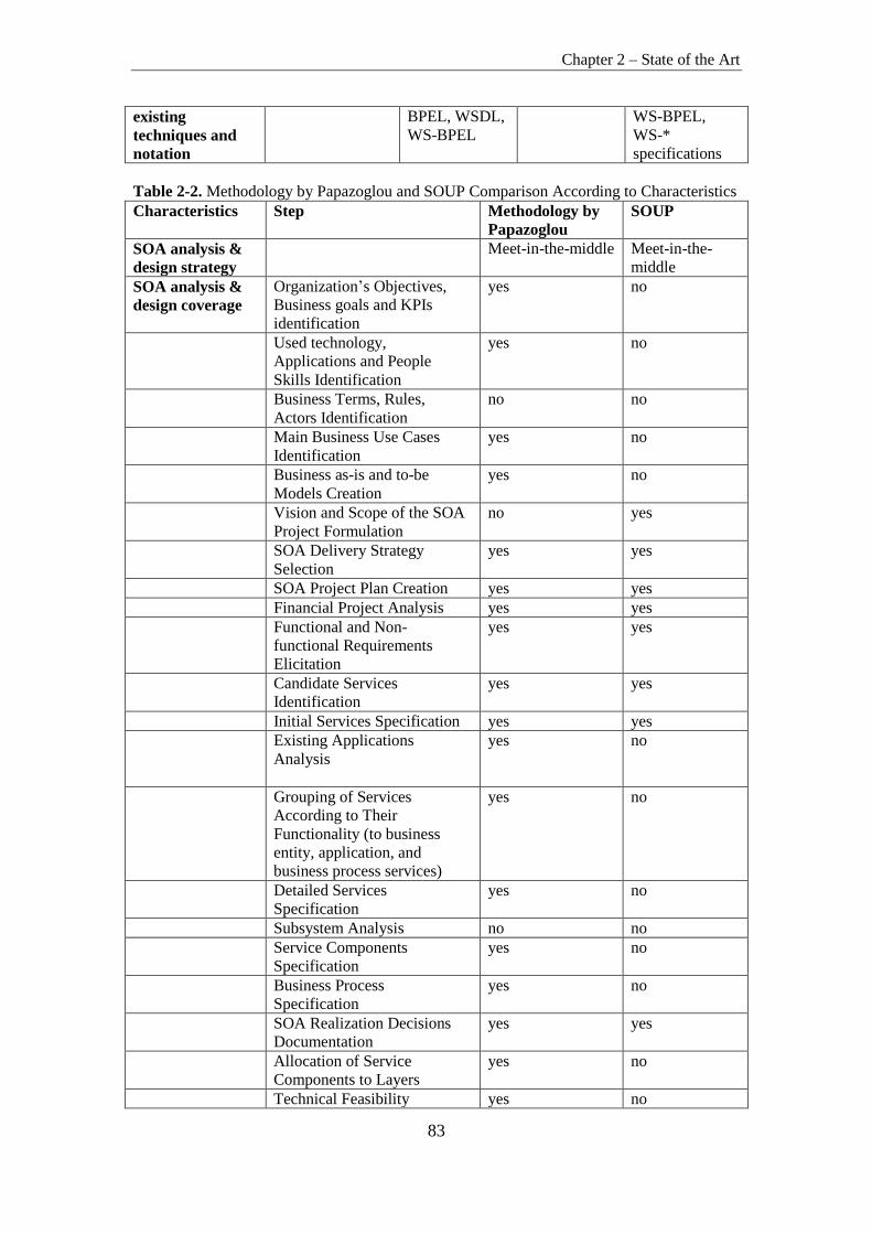
Chapter 2 – State of the Art
83
existing
techniques and
notation
BPEL, WSDL,
WS-BPEL
WS-BPEL,
WS-*
specifications
Table 2-2. Methodology by Papazoglou and SOUP Comparison According to Characteristics
Characteristics Step Methodology by
Papazoglou
SOUP
SOA analysis &
design strategy
Meet-in-the-middle Meet-in-the-
middle
SOA analysis &
design coverage
Organization’s Objectives,
Business goals and KPIs
identification
yes no
Used technology,
Applications and People
Skills Identification
yes no
Business Terms, Rules,
Actors Identification
no no
Main Business Use Cases
Identification
yes no
Business as-is and to-be
Models Creation
yes no
Vision and Scope of the SOA
Project Formulation
no yes
SOA Delivery Strategy
Selection
yes yes
SOA Project Plan Creation yes yes
Financial Project Analysis yes yes
Functional and Non-
functional Requirements
Elicitation
yes yes
Candidate Services
Identification
yes yes
Initial Services Specification yes yes
Existing Applications
Analysis
yes no
Grouping of Services
According to Their
Functionality (to business
entity, application, and
business process services)
yes no
Detailed Services
Specification
yes no
Subsystem Analysis no no
Service Components
Specification
yes no
Business Process
Specification
yes no
SOA Realization Decisions
Documentation
yes yes
Allocation of Service
Components to Layers
yes no
Technical Feasibility yes no

Chapter 2 – State of the Art
84
Exploration
Degree of
prescription
3 phases and main
activities are
described. Inputs
and outputs of are
provided not for all
activities.
2 phases lack of
cohesive
description. Not
all phases have
main activities
and key
deliverables
provided.
Adoption of
existing
techniques and
notation
CBD, BPM,
BPMN, WSDL,
BPEL, UML
No
2.3. Capturing Non-Functional Requirements for ESOA
Systems Using Viewpoints
For technical, human and environmental reasons, system requirements
specifications will always be imperfect. However, although perfection is
impossible, there is no doubt that much can be done to improve the quality of
most system specifications. It has been recognized for many years that
problems with specifications are probably the principal reason for project
failure where systems are delivered late, do not meet the real needs of their
users, and perform in an unsatisfactory way (Sommerville & Sawyer, 1997).
Improving the quality of specifications can be achieved in two ways
(Sommerville & Sawyer, 1997):
By improving the requirements engineering process so that errors are
not introduced into the specification.
By improving the organization and presentation of the specification
itself so that it is more amenable to validation.
An approach to system requirements engineering can be proposed, which
addresses both of these improvement dimensions. It is based on collecting and
analysing the requirements for ESOA systems from different viewpoints.
Viewpoints are entities that are widely used in software systems architecture
descriptions and which can be used to structure ESOA system requirements
(functional and non-functional) elicitation and specification.

Chapter 2 – State of the Art
85
The organization of architecture descriptions into views using viewpoints
provides a mechanism for the separation of concerns among the stakeholders
(ESOA stakeholders are discussed in details in Chapter 3.2 Stakeholders of
ESOA Systems), while providing a view of the whole system that is
fundamental to the notion of architecture.
A viewpoint is a subdivision of the specification of a complete system,
established to bring together those particular pieces of information relevant to
some particular area of concern during the analysis or design of the system.
Although separately specified, the viewpoints are not completely independent.
Key items in each are identified as related to items in the other viewpoints.
However, the viewpoints are sufficiently independent to simplify reasoning
about the complete specification.
Each software system has architecture. The system architecture has
architecture description. An architecture description includes one or more
architecture views. An architecture view addresses one or more of the concerns
of the system’s stakeholders. An architecture view expresses the architecture of
the system-of-interest in accordance with an architecture viewpoint. There are
two aspects to a viewpoint: the concerns it frames for stakeholders and the
conventions it establishes on views. An architecture viewpoint frames one or
more concerns. A concern can be framed by more than one viewpoint. A view
is governed by its viewpoint: the viewpoint establishes the conventions for
constructing, interpreting and analysing the view to address concerns framed
by that viewpoint. Viewpoint conventions can include languages, notations,
model kinds, design rules, and/or modelling methods, analysis techniques and
other operations on views.
In other words, a viewpoint is a specification of the conventions for
constructing and using a view. It is a pattern or template from which to develop
individual views by establishing the purposes and audience for a view and the
techniques for its creation and analysis. A view is what the stakeholders see
whereas the viewpoint defines the perspective from which the view is taken
and the methods for, and constraints upon, modelling that view.
Chapter 2 – State of the Art
86
Furthermore, viewpoints are independent of a particular system. In this way,
the system architect can select a set of candidate viewpoints first, or create new
viewpoints and then use those viewpoints to construct specific views that will
be used to organize the architectural description. A view, on the other hand, is
specific to a particular system. Therefore, the practice of creating an
architectural description involves, first, selecting the viewpoints and then using
those viewpoints to construct specific views for a particular system or
subsystem.
According to the Systems and software engineering – Architecture
description (ISO/IEC/IEEE 42010:2011) an architecture viewpoint shall
specify (for more detailed information regarding architecture description
standards refer to Chapters: 2.4.1 IEEE 1471:2000 Recommended Practice for
Architectural Description and 2.4.2 ISO/IEC/IEEE 42010:2011 Systems and
software engineering – Architecture description):
one or more concerns framed by this viewpoint;
typical stakeholders for concerns framed by this viewpoint;
one or more model kinds used in this viewpoint;
for each model kind identified in c), the languages, notations,
conventions, modelling techniques, analytical methods and/or other
operations to be used on models of this kind;
references to its sources.
Usually stakeholders have different expectations and non-functional
requirements may differ from one viewpoint to another and part of the
requirement analysis process is to detect and resolve such conflicts.
A viewpoint-based approach to requirements engineering recognizes that all
information about the system requirements cannot be discovered by
considering the system from a single perspective. Rather, there is a need to
collect and organize requirements from a number of different viewpoints. A
viewpoint is an encapsulation of partial information about a system’s
requirements. Information from different viewpoints must be integrated to in

Chapter 2 – State of the Art
87
order to form the final system specification. The principal arguments in favour
of a viewpoint-based approach to requirements engineering are (Sommerville
& Sawyer, 1997):
Systems usage is heterogeneous – there is no such thing as a typical
user. Viewpoints may organize system requirements from different
classes of system stakeholders.
Different types of information are needed to specify systems including
information about the application domain, information about the
system’s environment and engineering information about the system’s
development. Viewpoints may be used to collect and classify this
information.
Viewpoints may be used as a means of structuring the process of
requirements elicitation.
Viewpoints may be used to encapsulate different models of the system
each of which provides some specification information.
Viewpoints may be used to structure the requirements description and
expose conflicts between different requirements.
One of the aims in selecting a set of viewpoints is for them to be as loosely
coupled as possible. A benefit of using viewpoints is that they allow parallel
activities in different teams, and so allow some parts of the specification to
reach a level of stability and maturity before others. It takes some skill to pick
a good set of viewpoints: if two viewpoints are linked in too many ways, an
independent activity will be difficult.
Viewpoint modelling has become an effective approach for dealing with the
inherent complexity of large distributed systems. Current software architectural
practices, as described in standards ISO/IEC/IEEE 1471:2000 and
ISO/IEC/IEEE 42010:2011, divide the design activity into several areas of
concerns, each one focusing on a specific aspect of the system. Examples of
enterprise architecture frameworks that are based on ISO/IEC/IEEE 1471:2000

Chapter 2 – State of the Art
88
and ISO/IEC/IEEE 42010:2011 standards and employ viewpoints include the
following:
OASIS Reference Architecture Foundation for SOA – OASIS SOA
RAF) (2.4.4 OASIS Reference Architecture Foundation for SOA –
OASIS SOA RAF
Zachman Enterprise Architecture Framework (2.4.5 Zachman
Enterprise Architecture Framework )
The Open Group Architecture Framework – TOGAF (2.4.6 Open Group
Architecture Framework – TOGAF)
Extended Enterprise Architecture Framework (2.4.7. Extended
Enterprise Architecture Framework)
Department of Defence Architecture Framework – DoDAF (2.4.8
Department of Defence Architecture Framework – DoDAF
Kruchten’s “4+1”/RUP’s 4 + 1 View Model (2.4.9 Kruchten’s
“4+1”/RUP’s 4 + 1 View Model)
Siemens 4 views method (2.4.10 Siemens 4 views method)
Reference Model for Open Distributed Processing – RM-ODP (2.4.11
Reference Model for Open Distributed Processing).
2.4. Enterprise Architecture Frameworks and Standards
As described in standard (IEEE Std 1471:2000), an architecture is the
fundamental organization of a system, embodied in its components, their
relationships to each other and the environment, and the principles governing
its design and evolution.
Architecture is important for at least three reasons (Minoli, 2008). It enables
communication among stakeholders, facilitates early design decisions, and
creates a transferable abstraction of a system/environment description
(Fernandez-Martinez & Lemus-Olalde, 2004).
Enterprise architecture work, when done correctly, provides a systematic
assessment and description of how the business function operates at the current

Chapter 2 – State of the Art
89
time - it provides a “blueprint” of how it should operate in the future, and, it
provides a roadmap for getting to the target state. The purpose of enterprise
architecture is to create a map of IT assets and business processes and a set of
governance principles and/or enterprise standards that drive an ongoing
discussion about business strategy and how it can be expressed through IT.
There are many different frameworks suggested to develop enterprise
architecture as discussed in the following sections. However, most frameworks
contain the following four basic architecture domains (Minoli, 2008):
1. business architecture – documentation that outlines the company’s most
important business processes. This architecture is the most critical, but
also the most difficult to implement, according to industry practitioners
(Koch, 2005),
2. information architecture – identifies where important blocks of
information, such as a customer record, are kept and how one typically
accesses them,
3. application system architecture – a map of the relationships of software
applications to one another,
4. infrastructure technology architecture – a blueprint for the gamut of
hardware, storage systems, and networks.
Layered frameworks and models for enterprise architecture have proved useful
because layering has the advantage of defining contained, non-overlapping
partitions of the environment. However, at this time no complete industry wide
consensus exists on what an architectural layered model should be, therefore
various models exist or can be used.
In the context of architecture, an important recent development in IT
architecture practice has been the emergence of standards for architecture
description and architecture frameworks. The list of EA frameworks and
standards used in research is described in the sections bellow.

Chapter 2 – State of the Art
90
2.4.1. IEEE 1471:2000 Recommended Practice for Architectural
Description
The IEEE 1471:2000 Recommended Practice for Architectural Description
(IEEE Std 1471:2000) standard aims to promote a more consistent, systematic
approach to the creation of architectural views. The standard introduces a
conceptual model that integrates mission, environment, system architecture,
architecture description, rationale, stakeholders, concerns, viewpoints, views,
and architectural models facilitating the expression, communication,
evaluation, and comparison of architectures in a consistent manner (Fernandez-
Martinez, & Lemus-Olalde, 2004). IEEE 1471:2000 contains a conceptual
framework for architectural description and a statement of what information
must be found in any IEEE 1471:2000 compliant architectural description. The
conceptual framework described in the standard ties together such concepts as
system, architectural description, and view (Clements, 2005). The conceptual
framework illustrated in Figure 2-7 and Figure 2-8 can be described as follows
(IEEE Std 1471:2000):
A system has an architecture;
An architecture is described by one or more architecture descriptions;
An architecture description is composed of one or more of stakeholders,
concerns, viewpoints, views, and models;
A stakeholder has one or more concerns;
A concern has one or more stakeholders;
A viewpoint covers one or more concerns and stakeholders;
A view conforms to one viewpoint;
A viewpoint defines the method of a model;
A view has one or more models, and a model is part of one or more
views;
A viewpoint library is composed of viewpoints.

Chapter 2 – State of the Art
91
Figure 2-7. Conceptual Framework of IEEE 1471:2000 (partial view; Minoli, 2008)
Figure 2-8. Conceptual Framework of IEEE 1471:2000 (larger view; IEEE Std 1471:2000)
2.4.2. ISO/IEC/IEEE 42010:2011 Systems and software engineering –
Architecture description
ISO/IEC/IEEE 42010:2011 Systems and Software Engineering – Architecture
description (ISO/IEC/IEEE 42010:2011) is a predecessor of IEEE 1471:2000.
The standard, published in 2011 (WEB, i), is the result of a joint ISO and IEEE
revision of the earlier IEEE Std 1471:2000, IEEE Recommended Practice for

Chapter 2 – State of the Art
92
Architectural Description of Software-Intensive Systems. IEEE 1471:2000 was
developed by the IEEE Architecture Working Group under the sponsorship of
the IEEE Software Engineering Standards Committee. In September 2000, the
IEEE Standards Board approved IEEE 1471:2000 for use. In March 2006,
IEEE 1471:2000 was adopted as an ISO standard. It was published in July
2007 as ISO/IEC 42010:2007. Its text was identical to IEEE 1471:2000.
ISO/IEC/IEEE 42010:2011 replaces ISO/IEC 42010:2007 and IEEE Std
1471:2000.
2.4.3. IEEE P1723 Standard for Service-Oriented Architecture (SOA)
Reference Architecture
This standard (IEEE P1723) is a new IEEE project (not finished standard). It
will define a reference architecture specification, which will include guidance
necessary for the development of SOA. It will provide a minimum
implementation subset that allows straightforward identification and
configuration of service-oriented solutions with vendor extensibility, which
will provide for growth and product differentiation. The standard is limited to
design and modelling of service-oriented solution architecture and does not
include design or modelling of service-oriented implementation and supporting
infrastructures.
2.4.4. OASIS Reference Architecture Foundation for SOA – OASIS SOA
RAF
OASIS Reference Architecture Foundation for SOA – SOA-RAF (SOA-RAF,
2012) describes the foundation upon which Service-Oriented Architectures can
be built. It follows the concepts and relationships defined in the OASIS
Reference Model for Service-Oriented Architecture (SOA-RM, 2006). The
OASIS Reference Model for SOA identifies the key characteristics of SOA
and defines many of the important concepts needed to understand what SOA is
and what makes it important. SOA-RAF takes the Reference Model as its
starting point, in particular, the vocabulary and definition of important terms

Chapter 2 – State of the Art
93
and concepts. SOA-RAF goes further in that it shows how SOA systems can be
realized, albeit in an abstract way. The focus of SOA-RAF is on an approach to
integrating business with the information technology needed to support it. The
result – Reference Architecture – is an abstract realization of SOA, focusing on
the elements and their relationships needed to enable SOA systems to be used,
realized and owned while avoiding reliance on specific concrete technologies.
This is not a complete blueprint for realizing SOA systems. It does identify
many of the key aspects and components that will be present in any well
designed SOA system. In order to actually use, construct and manage SOA
systems, many additional design decisions and technology choices will need to
be made. SOA-RAF is of value to Enterprise Architects, Business and IT
Architects as well as CIOs and other senior executives involved in strategic
business and IT planning. As with the Reference Model (SOA-RM), SOA-
RAF is primarily focused on large-scale distributed IT systems where the
participants may be legally separate entities. It is quite possible for many
aspects of this Reference Architecture to be realized on quite different
platforms.
The SOA-RAF follows the recommended practice of describing architecture in
terms of models, views, and viewpoints, as prescribed in the IEEE 1471:2000
(IEEE Std 1471:2000). The SOA-RAF structures its analysis based on the
concepts defined in IEEE Recommended Practice for Architectural Description
of Software-Intensive Systems IEEE 1471:2000, which was later approved as
ISO/IEC 42010:2007 and subsequently superseded by ISO/IEC/IEEE
42010:2011 (ISO/IEC/IEEE 42010:2011).
Many systems cannot be completely understood by a simple decomposition
into parts and subsystems, in particular, when many autonomous parts of the
system are governing interactions. There is a need to understand the context
within which the system functions. This is the ecosystem (SOA-RAF, 2012).
SOA-RAF views the SOA architectural paradigm from an ecosystems
perspective: whereas a system will be a capability developed to fulfil a defined
set of needs, a SOA ecosystem is a space in which people, processes and

Chapter 2 – State of the Art
94
machines act together to deliver those capabilities as services. In a SOA
ecosystem there may not be a single person or organization that is really “in
control” or “in charge” of the whole although there are identifiable
stakeholders who have influence within the community and control over
aspects of the overall system.
SOA-RAF provides three main views (SOA-RAF, 2012) that are based on the
SOA Ecosystem concept:
3. Participation in a SOA Ecosystem view – focuses on the way that
participants are part of a SOA ecosystem.
4. Realization of a SOA Ecosystem view – addresses the requirements for
constructing a SOA system in a SOA ecosystem.
5. Ownership in a SOA Ecosystem view – focuses on what it means to own a
SOA system.
The SOA-RAF views conform to three viewpoints (named after views). There
is a one-to-one correspondence between viewpoints and views.
Participation in a SOA Ecosystem Viewpoint (SOA-RAF, 2012) captures an
SOA ecosystem as an environment for people to conduct their business. The
applicability of such an ecosystem is not limited to commercial and enterprise
systems. The term “business” is used to include any transactional activity
between multiple participants. All stakeholders in the ecosystem have concerns
addressed by this viewpoint. The primary concern for people is to ensure that
they can conduct their business effectively and safely in accordance with the
SOA paradigm. The primary concern of decision makers is the relationships
between people and organizations using systems for which they, as decision
makers, are responsible but which they may not entirely own, and for which
they may not own all of the components of the system. Given SOA’s value in
allowing people to access, manage and provide services across ownership
boundaries, those boundaries and the implications of crossing them must be
explicitly identified.
Realization of a SOA Ecosystem Viewpoint (SOA-RAF, 2012) focuses on the
infrastructure elements that are needed to support the construction of SOA

Chapter 2 – State of the Art
95
systems. The stakeholders are essentially anyone involved in designing,
constructing and deploying a SOA system. They are concerned with the
application of well-understood technologies that available to system architects
to realize the SOA vision of managing systems and services that cross
ownership boundaries.
Ownership in a SOA Ecosystem Viewpoint (SOA-RAF, 2012) addresses the
concerns involved in owning and managing SOA systems within the SOA
ecosystem. Many of these concerns are not easily addressed by automation;
instead, they often involve people-oriented processes such as governance
bodies. Owning an SOA system implies being able to manage an evolving
system. It involves playing an active role in a wider ecosystem. This viewpoint
is concerned with how systems are managed effectively, how decisions are
made and promulgated to the required end points, how to ensure that people
may use the system effectively and how the system can be protected against,
and recover from consequences of, malicious intent.
2.4.5. Zachman Enterprise Architecture Framework
The Zachman Framework establishes a common vocabulary and set of
perspectives for defining and describing complex enterprise systems (Minoli,
2008). More specifically, the Zachman Framework is ontology (Zachman,
2011) – a theory of the existence of a structured set of essential components of
an object for which explicit expressions is necessary and perhaps even
mandatory for creating, operating, and changing the object (the object being an
Enterprise, a department, a value chain, a solution, a project, an airplane, a
building, a product, a profession). The Zachman Framework is not a
methodology for creating the implementation of the object. The Zachman
Framework is ontology for describing the Enterprise. Ontology is a structure
whereas a methodology is a process. A structure is not a process. A structure
establishes definition whereas a process provides transformation (Zachman,
2011).

Chapter 2 – State of the Art
96
Since its first publication in 1987, the Zachman Framework has evolved and
become the model around which major organizations worldwide view and
communicate their enterprise architecture (this research is based only on the
newest Zachman Framework 3.0 version). John Zachman based his framework
on practices in traditional architecture and engineering. This resulted in an
approach where a two dimensional logical template is created to synthesize the
framework. The framework contains six rows and six columns yielding 36
cells. The horizontal axis provides multiple perspectives coupled with the
following concepts and models for their description:
executive perspective describes scope, business context and provides
scope identification lists,
business management perspective describes business concepts provides
and business definition models,
architect perspective describes system logic and provides system
representation models,
engineer perspective describes technology physics and provides
technology specification models,
technician perspective describes tool components and provides tool
configuration models,
enterprise (users) perspective describes operation instances and
provides the implementation for the enterprise.
The drill down through perspectives is derived from reification, the
transformation of an abstract idea into an instantiation that was initially
postulated by ancient Greek philosophers and is labelled in the Zachman
Framework as Identification, Definition, Representation, Specification,
Configuration and Instantiation.
The vertical axis provides a classification of the various artefacts of the
architecture according to the questions What, How, When, Who, Where, and
Why.

Chapter 2 – State of the Art
97
2.4.6. Open Group Architecture Framework – TOGAF
The Open Group is a vendor-neutral and technology-neutral consortium
seeking to enable access to integrated information, within and among
enterprises, based on open standards and global interoperability (Minoli, 2008).
The Open Group developed an architectural framework known as the Open
Group Architecture Framework – TOGAF. It is described in a set of
documentation published by the Open Group on its public web server, and may
be used freely by any organization wishing to develop enterprise architecture
for use within that organization. The original development of TOGAF Version
1 in 1995 was based on the Technical Architecture Framework for Information
Management – TAFIM (TAFIM, 1990), which was developed by the US
Department of Defence – DoD. The DoD gave the Open Group explicit
permission and encouragement to create TOGAF by building on the TAFIM,
which itself was the result of many years of development effort and many
millions of dollars of US Government investment (TOGAF 9.1, 2011).
TOGAF embraces but does not strictly adheres to ISO/IEC 42010:2007
terminology.
TOGAF’s core taxonomy of architecture views defines the minimum set of
views that should be considered in the development of enterprise architecture.
Because in ISO/IEC 42010:2007 every view has an associated viewpoint that
defines it, this may also be regarded as taxonomy of viewpoints by those
organizations that have adopted ISO/IEC 42010:2007 (Minoli, 2008).
The architecture views, and corresponding viewpoints, that may be created to
support each of these stakeholders fall into the following categories:
Business Architecture Views which address the concerns of the users
of the system, and describe the flows of business information between
people and business processes.
Data Architecture Views which address the concerns of database
designers and database administrators, and system engineers responsible

Chapter 2 – State of the Art
98
for developing and integrating the various database components of the
system.
Applications Architecture Views which address the concerns of
system and software engineers responsible for developing and
integrating the various application software components of the system.
Technology Architecture Views which address the concerns of
Acquirers (procurement personnel responsible for acquiring the
commercial off-the-shelf – COTS software and hardware to be included
in the system), operations staff, systems administrators, and systems
managers.
Examples of specific views that may be created in each category are given in
Table 2-3 (Minoli, 2008; Web, l).
Table 2-3. TOGAF ADM Views (TOGAF 9.1, 2011)
Users, Planners,
and Business
Management
Database
Designers,
Administrators,
and System
Engineers
System and
Software
Engineers
Acquirers,
Operators,
Administrators,
and Managers
Business
Architecture
Views
Data Architecture
Views
Applications
Architecture
Views
Technology
Architecture
Views
Business Function
View
Data Entity View Software
Engineering View
Networked
Computing/
Hardware View Business Services
View
Business Process
View
Business
Information View
Business Locations
View
Communications
Engineering View
Business Logistics
View
Data Flow View
(organization
data use)
Applications
Interoperability
View People View
(organization chart)
Processing View
Workflow View
Usability View
Business Strategy
and Goals View
Logical Data View Software
Distribution View
Cost View
Business

Chapter 2 – State of the Art
99
Objectives View
Business Rules
View
Standards View
Business Events
View
Business
Performance View
System Engineering View
Enterprise Security View
Enterprise Manageability View
Enterprise Quality of Service View
Enterprise Mobility View
2.4.7. Extended Enterprise Architecture Framework
The Extended Enterprise Architecture – E2A and Extended Enterprise
Architecture Framework – E2AF have been developed by the Institute for
Enterprise Architecture Developments – IFEAD. E2AF addresses three major
elements in a holistic way: the element of construction, the element of
function, and the element of style that reflects the culture, values, norms, and
principles of an organization (Minoli, 2008).
Often, the term enterprise architecture deals with construction and function,
without due consideration of the stylistic aspect. The stylistic aspect reflects
the cultural behaviour, values, norms, and principles of an organization in such
a way that it reflects its corporate values (Schekkerman, 2005). At the same
time, the enterprise architecture addresses the aspects of business, information,
information systems, and technology infrastructure in a holistic way covering
the organization and its environment (Minoli, 2008; Schekkerman, 2005).
E2AF is based on the concepts described in IEEE 1471-2000 (IEEE Std
1471:2000) regarding views and viewpoints and the transformation of these
concepts into the enterprise architecture domain enables another perspective of
viewpoints and views.
From the concept of architecture viewpoints another, a relatively new view on
enterprise architecture sets of viewpoints is introduced, to reflect extended
enterprise stakeholders responsibilities and involvement in organisations and
societies.

Chapter 2 – State of the Art
100
Extended Enterprise Architecture Viewpoint Sets are themes of viewpoints that
can be determined based on different ways to look at the enterprise and its
environment. Despite the variety of stakeholder groups and their demands in
Enterprises, stakeholders’ responsibilities can be classified into four broad sets
of extended enterprise architecture viewpoints: Economic, Legal, Ethical, and
Discretionary responsibilities.
Economic set of viewpoints (Schekkerman, 2004). As social economic
elements, organizations are expected to generate and sustain profitability, offer
goods and services that are both desired and desirable in society and of good
quality, and reward employees and other elements that help create success. To
satisfy these expectations, organizations develop strategies to keep abreast of
changing customer/citizen needs, to compensate employees and investors
fairly, and to continually improve and innovate the effectiveness and efficiency
of organizational processes. A long-term perspective is essential when
establishing these strategies: A responsible organization must continue to earn
profits from its ongoing activities in order to benefit its stakeholders. Examples
of economic viewpoints are Benefits, Costs, Quality, Innovation and etc.
Legal set of viewpoints (Schekkerman, 2004). Regardless of their economic
achievements, organizations must abide by established laws and regulations in
order to socially responsible. Even so the privacy legislations have to be
respected. The identification of legal issues and implementation of compliancy
requirements are the best approach to preventing violations and costly
litigation. Accounting and control mechanisms have to be in place according to
the rules and legislations. Examples of legal viewpoints are Law &
Regulations, Privacy, Accounting & Assessment etc.
Ethical set of viewpoints (Schekkerman, 2004). The establishment of strict
ethical standards in the workplace may also be an excellent way to prevent
legal violations by creating a focus on integrity in management style. In
addition, an organization guided by strong ethical values may also be better
able to satisfy ethical responsibilities, the third type of responsibility imposed
by enterprise stakeholders. Incorporating ethical standards and handling in
Chapter 2 – State of the Art
101
corporate culture will create respectful organizations where the corporate
governance structure reflects these ethics and where people are involved in
identifying legal violations, corporate risks and security vulnerabilities.
Examples of Ethical viewpoints are Culture, Strategy, Risk etc.
Discretionary set of viewpoints (Schekkerman, 2004). In addition to meeting
economic, legal, and ethical responsibilities, organizations are also expected to
display a genuine concern for the general welfare of all
constituencies. Companies must balance the costs of these discretionary
activities against the costs of manufacturing and marketing their products or
services in a responsible manner. An example of Discretionary viewpoints is
stakeholder groups’ individual perspectives or specific enterprise stakeholder
themes etc.
2.4.8. Department of Defence Architecture Framework – DoDAF
The Department of Defence Architecture Framework – DoDAF – is an
architecture framework for the United States Department of Defence – DoD
that provides visualization infrastructure for specific stakeholders concerns
through viewpoints organized by various views (DoDAF v2.02, 2010). The
purpose of DoDAF is to ascertain that architectural descriptions developed by
various commands, services, and agencies are compatible and interrelatable
and that technical architecture views are usable and integral across
organizational domains. This framework addresses the military domain and is
used primarily by the Department of Defence. Like any other architecture
framework, it provides rules and guidance for developing and presenting
architecture descriptions, including artefacts. It provides input on how to
describe architectures, but it does not provide mechanisms in how to construct
or implement a specific architecture or how to develop and acquire systems or
systems of systems.
The current official DODAF version 2.02 was released in August 2010. In
DoDAF V2.0, architectural viewpoints are composed of data that has been
organized to facilitate understanding. In order to align with ISO Standards like

Chapter 2 – State of the Art
102
ISO/IEC 42010:2007, where appropriate, the terminology has changed from
View to Viewpoint (e.g., the Operational View is now the Operational
Viewpoint). DODAF version 2.02 proposes eight viewpoints. Viewpoints
proposed by DoDAF are described as follows:
All Viewpoint (DoDAF v2.02, 2010) describes the overarching aspects of
architecture context that relate to all viewpoints. AV viewpoint models provide
information pertinent to the entire Architectural Description rather than
representing a distinct viewpoint. AV models provide an overview of the
architectural effort including such things as the scope, context, rules,
constraints, assumptions, and the derived vocabulary that pertains to the
Architectural Description.
Capability Viewpoint (DoDAF v2.02, 2010) articulates the capability
requirements, the delivery timing, and the deployed capability. CV viewpoint
models address the concerns of Capability Portfolio Managers. In particular,
the Capability Models describe capability taxonomy and capability evolution.
The Capability Models included within DoDAF are based on the program and
capability information used by Portfolio Managers to capture the increasingly
complex relationships between interdependent projects and capabilities.
Data and Information Viewpoint (DoDAF v2.02, 2010) articulates the data
relationships and alignment structures in the architecture content for the
capability and operational requirements, system engineering processes, and
systems and services. DIV viewpoint models provide a means of portraying the
operational and business information requirements and rules that are managed
within and used as constraints on the organizations business activities.
Operational Viewpoint (DoDAF v2.02, 2010) includes the operational
scenarios, activities, and requirements that support capabilities. OV Viewpoint
models describe the tasks and activities, operational elements, and resource
flow exchanges required to conduct operations.
Project Viewpoint (DoDAF v2.02, 2010) describes the relationships between
operational and capability requirements and the various projects being
implemented. PV also details dependencies among capability and operational

Chapter 2 – State of the Art
103
requirements, system engineering processes, systems design, and services
design within the Defence Acquisition System process. PV viewpoint models
describe how programs, projects, portfolios, or initiatives deliver capabilities,
the organizations contributing to them, and dependencies between them.
Services Viewpoint (DoDAF v2.02, 2010) presents the design for solutions
articulating the Performers, Activities, Services and their exchanges, providing
for or supporting operational and capability functions. SvcV viewpoint models
describe services and their interconnections providing or supporting, DoD
functions. DoD functions include both warfighting and business functions. The
Service Models associate service resources to the operational and capability
requirements.
Standards Viewpoint (StdV) articulates the applicable operational, business,
technical, and industry policies, standards, guidance, constraints, and forecasts
that apply to capability and operational requirements, system engineering
processes, and systems and services. StdV viewpoint models describe the set of
rules governing the arrangement, interaction, and interdependence of parts or
elements of the Architectural Description.
Systems Viewpoint (DoDAF v2.02, 2010) articulates for legacy support, the
design for solutions articulating the systems, their composition,
interconnectivity, and context providing for or supporting operational and
capability functions. SV viewpoint models describe systems and
interconnections providing for, or supporting, DoD functions. DoD functions
include both warfighting and business functions. The Systems Models
associate systems resources to the operational and capability requirements.
There exists another Enterprise Architecture Framework that is closely related
to DODAF – Ministry of Defence Architecture Framework – MODAF. It is
an internationally recognised enterprise architecture framework developed by
the Ministry of Defence (MOD) to support defence planning and change
management activities. MODAF proposes the following set of viewpoints:
Strategic Viewpoint (StV), Operational Viewpoint (OV), Service Orientated

Chapter 2 – State of the Art
104
Viewpoint (SOV), Systems Viewpoint (SV), Acquisition Viewpoint (AcV),
Technical Viewpoint (TV) and All Viewpoint (AV).
The Unified Profile for DoDAF/MODAF – UPDM is the product of an
Object Management Group (OMG) initiative to develop a modelling standard
that supports both the USA Department of Defence Architecture Framework
(DoDAF) and the UK Ministry of Defence Architecture Framework
(MODAF).
2.4.9. Kruchten’s “4+1”/RUP’s 4 + 1 View Model
The Rational Unified Process (RUP) is a software development process
developed and commercialized by Rational Software, now IBM (Kroll, et. al,
2003). RUP software architecture encompasses a set of significant decisions
about the organization of a software system:
• selection of the structural elements and their interfaces by which a system
is composed,
• behaviour as specified in collaborations among those elements,
• composition of these structural and behavioural elements into larger
subsystem,
• architectural style that guides this organization.
Software architecture also involves: usage, functionality, performance,
resilience, reuse, comprehensibility, economic and technology constraints and
trade-offs, and aesthetic concerns.
RUP defines an architectural design method, using the concept of 4 + 1 views
(Kruchten, 1995) four views to describe the design: logical view, process view,
implementation view and deployment view, and using a use-case or scenario
view (+1) to relate the design to the context and goals.
Logical view (Kruchten, 1995). The logical view is concerned with the
functionality that the system provides to end-users. UML Diagrams used to
represent the logical view include Class diagram, Communication diagram and
Sequence diagram.
Chapter 2 – State of the Art
105
Development view (Kruchten, 1995). The development view illustrates a
system from a programmer's perspective and is concerned with software
management. This view is also known as the implementation view. It uses the
UML Component diagram to describe system components. UML Diagrams
used to represent the development view include the Package diagram.
Process view (Kruchten, 1995). The process view deals with the dynamic
aspects of the system, explains the system processes and how they
communicate, and focuses on the runtime behaviour of the system. The process
view addresses concurrency, distribution, integrators, performance, and
scalability etc. UML Diagrams to represent process view include the Activity
diagram.
Physical view (Kruchten, 1995). The physical view depicts the system from a
system engineer's point-of-view. It is concerned with the topology of software
components on the physical layer, as well as the physical connections between
these components. This view is also known as the deployment view. UML
Diagrams used to represent physical view include the Deployment diagram.
Scenarios (Kruchten, 1995). The description of architecture is illustrated using
a small set of use cases, or scenarios which become a fifth view. The scenarios
describe sequences of interactions between objects, and between processes.
They are used to identify architectural elements and to illustrate and validate
the architecture design. They also serve as a starting point for tests of an
architecture prototype. This view is also known as use case view.
2.4.10. Siemens 4 views method
The Siemens Four-Views (S4V) method (Hofmeister et al, 2000; Soni et al,
1995), developed at Siemens Corporate Research, is based on best architecture
practices for industrial systems. The four views: conceptual, execution, module
and code architecture view, separate different engineering concerns, thus
reducing the complexity of the architecture design task.

Chapter 2 – State of the Art
106
In the Conceptual View (Soni et al, 1995), the product’s functionality is
mapped to a set of decomposable, interconnected components and connectors.
Components are independently executing peers, as are connectors. The primary
engineering concerns in this view are to address how the system fulfils the
requirements. The functional requirements are a central concern, including
both the current requirements and anticipated future enhancements. Global
properties such as performance and dependability are addressed here as well as
in the execution view. The system’s relationship to a product family, the use of
COTS, and the use of domain-specific hardware and/or software are all
addressed in the conceptual view as well as in the module view.
For the Module View (Soni et al, 1995), modules are organized into two
orthogonal structures: decomposition and layers. The decomposition structure
captures how the system is logically decomposed into subsystems and
modules. A module can be assigned to a layer, which then constrains its
dependencies on other modules. The primary concerns of this view are to
minimize dependencies between modules, maximize the reuse of modules, and
support testing. Another key concern is to minimize the impact of future
changes in COTS software, the software platform, domain-specific hardware
and software, and standards.
The Execution Architecture View (Soni et al, 1995) describes the system’s
structure in terms of its runtime platform elements (e.g., OS tasks, processes,
threads). The task for this view is to assign the system’s functionality to these
platform elements, determine how the resulting runtime instances
communicate, and how physical resources are allocated to them. Other
considerations are the location, migration, and replication of these runtime
instances. Runtime properties of the system, such as performance, safety, and
replication must be addressed here.
The last view, the Code Architecture View (Soni et al, 1995), is concerned
with the organization of the software artefacts. Source components implement
elements in the module view, and deployment components instantiate runtime
entities in the execution view. The engineering concerns of this view are to

Chapter 2 – State of the Art
107
make support product versions and releases, minimize the effort for product
upgrades, minimize build time, and support integration and testing.
2.4.11. Reference Model for Open Distributed Processing
The aim of the Reference Model for Open Distributed Processing (the RM-
ODP) is to provide an architectural framework for the standardization of open
distributed processing – ODP. ODP supports distribution, interworking,
platform and technology independence, and portability, together with an
enterprise architecture framework for the specification of ODP systems (RM-
ODP). The RM-ODP defines a framework, but not a methodology (Linington
et al, 2011). It gives the designer a way of thinking about the system, and
structuring its specification, but does not constrain the order in which the
design steps should be carried out. There are many popular design processes,
and the framework can be used with practically any of them.
The RM-ODP is a reference model based on precise concepts derived from
current distributed processing developments and, as far as possible, on the use
of formal description techniques for specification of the architecture. The
Reference Model was published in the mid-1990s, following almost ten years
of work at the International Standards Organization to harvest the best
architectural work up to that time. The results were published as common text
by both ISO and the ITU-T (the telecommunications standards forum). The
RM-ODP was published in four parts: Overview (ISO/IEC 10746-1:1998),
Foundations (ISO/IEC 10746-2:1996), Architecture (ISO/IEC 10746-3:1996),
Architectural Semantics (ISO/IEC 10746-4:1998). These four parts provide an
introduction, a set of rigorous basic concepts, the architectural framework, and
a link to supporting formal techniques. The users of this framework are
expected to be system designers, but it is also intended to help people who
build tools to support such design activity, or who produce standards to capture
best practice and reusable mechanisms in this area.
The RM-ODP is perhaps best known for its use of viewpoints (Linington et al,
2011). The idea behind them is to break down a complex specification into a

Chapter 2 – State of the Art
108
set of coupled but separate pieces. The writers of the reference model were
keenly aware of the need to serve different stakeholders, and introduced the
idea of there being a set of linked viewpoints to maintain extensibility and
avoid the difficulties associated with constructing and maintaining a single
large system description.
Therefore, the ODP reference model defines five specific viewpoints intended
to appeal to five clear groups of users of a whole family of standards.
The Enterprise Viewpoint (Linington et al, 2011) focuses on the organizational
situation in which the design activity is to take place. It concentrates on the
objectives, business rules and policies that need to be supported by the system
being designed. The stakeholders to be satisfied are therefore the owners of the
business processes being supported and the managers responsible for the
setting of operational policies. The emphasis is on business and social units
and their interdependencies.
The Information Viewpoint (Linington et al, 2011) concentrates on the
modelling of the shared information manipulated within the enterprise of
interest. The creation of an information specification has broadly the same
objectives that creation of a data dictionary had for previous generations. By
providing a common model that can be referenced from throughout a complete
piece of design, we can ensure that the same interpretation of information is
applied at all points. As a result, we can avoid the divergence of use and
incomplete collection of information that would result from separate members
of the design team each making their own decisions about interpretation.
The Computational Viewpoint (Linington et al, 2011) is concerned with the
development of the high-level design of the processes and applications
supporting the enterprise activities. It uses the familiar tools for object-oriented
software design, ex-pressing its models in terms of objects with strong
encapsulation boundaries, interacting at typed interfaces by performing a
sequence of operations (or passing continuous streams of information). The
computational specification makes reference to the information viewpoint for
the definitions of data objects and their behavioural constraints.

Chapter 2 – State of the Art
109
The Engineering Viewpoint (Linington et al, 2011) tackles the problem of
diversity in infrastructure provision; it gives prescriptions for supporting the
necessary abstract computational interactions in a range of different situations.
It thereby offers a way to avoid lock-in to specific platforms or infrastructure
mechanisms. A particular interaction may involve communication between
subsystems, or between objects co-located in a single application server, and
different engineering solutions will be used depending on which is currently
the case. The engineering specification is akin to the specification of how
middleware is provided; there are different solutions for use in different
operating environments, but the aim is to provide a consistent set of
communication services and other supporting services that the application
designer can rely on in all cases.
The Technology Viewpoint (Linington et al, 2011) is concerned with
managing real world constraints, such as restrictions on the hardware available
to implement the system within budget, or the existing application platforms
on which the applications must run. The designer never really has the luxury of
starting with a green field, and this viewpoint brings together information
about the existing environment, current procurement policies and configuration
issues. It is concerned with selection of ubiquitous standards to be used in the
system, and the allocation and configuration of real resources. It represents the
hardware and software components of the implemented system, and the
communication technology that provides links between these components.
Bringing all these factors together, it expresses how the specifications for an
ODP system are to be implemented. This viewpoint also has an important role
in the management of testing conformance to the overall specification because
it specifies the information required from implementers to support this testing.
2.4.12. Comparison of Enterprise Architecture Frameworks
After analysing Enterprise Architecture Frameworks, we came to the
conclusion that The Open Group Architecture Framework – TOGAF (2.4.6

Chapter 2 – State of the Art
110
Open Group Architecture Framework – TOGAF) is a very good baseline for
our Enterprise Architecture Frameworks Viewpoints comparison. Furthermore,
we decided to structure comparison based on TOGAF ADM views categories:
Business Architecture Views, Data Architecture Views, Applications
Architecture Views, and Technology Architecture Views. As TOGAF adheres
to ISO/IEC 42010:2007 standard, where every view has an associated
viewpoint that defines it, TOGAF ADM views may also be regarded as
viewpoints. As a result, we used TOGAF architecture view categories in our
comparison. Moreover, these view categories can be directly mapped to
architecture domains – Business Architecture, Information Architecture,
Application System Architecture, Infrastructure Technology Architecture
described in (Minoli, 2008). Most of Enterprise Architecture Frameworks are
based on these architecture domains. Moreover, each architecture viewpoint
group has a group of users, those concerns are framed by the viewpoint (the
first and second lines in Table 2-4). The result of Enterprise Architecture
Frameworks comparison and mapping into architecture domains is depicted in
Table 2-4.
Table 2-4. Comparison/Mapping of Enterprise Architecture Framework Views/Viewpoints
Users, Planners,
and Business
Management
Database
Designers,
Administrators,
and System
Engineers
System and
Software
Engineers
Acquirers,
Operators,
Administrators,
and Managers
Business
Architecture
Views/Viewpoints
Data Architecture
Views/Viewpoints
Applications
Architecture
Views/Viewpoints
Technology
Architecture
Views/Viewpoints
The Open Group Architecture Framework - TOGAF
Business Function
View
Data Entity View Software
Engineering View
Networked
Computing/
Hardware View Business Services
View
Business Process
View
Business
Information View
Business Locations
View
Communications
Engineering View

Chapter 2 – State of the Art
111
Business Logistics
View
Data Flow View
(organization
data use)
Applications
Interoperability
View People View
(organization chart)
Processing View
Workflow View
Usability View
Business Strategy
and Goals View
Logical Data View Software
Distribution View
Cost View
Business
Objectives View
Business Rules
View
Standards View
Business Events
View
Business
Performance View
System Engineering View
Enterprise Security View
Enterprise Manageability View
Enterprise Quality of Service View
Enterprise Mobility View
OASIS Reference Architecture Foundation for SOA (OASIS SOA RAF)
Participation in a
SOA Ecosystem
view
Realization of a SOA Ecosystem view
Ownership in a
SOA Ecosystem
view
Zachman Enterprise Architecture Framework
executive
viewpoint
architect viewpoint
engineer viewpoint
business
management
viewpoint
enterprise (users)
viewpoint
Extended Enterprise Architecture Framework
Economic set of
viewpoints
Legal set of
viewpoints
Ethical set of
viewpoints
Discretionary set of
viewpoints
Governance
Viewpoint
Security and
Privacy Viewpoints
Department of Defence Architecture Framework (DoDAF)
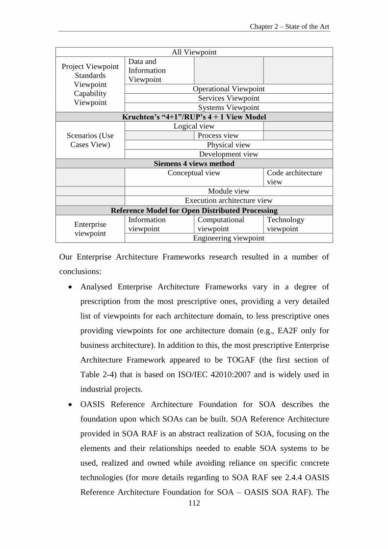
Chapter 2 – State of the Art
112
All Viewpoint
Project Viewpoint
Standards
Viewpoint
Capability
Viewpoint
Data and
Information
Viewpoint
Operational Viewpoint
Services Viewpoint
Systems Viewpoint
Kruchten’s “4+1”/RUP’s 4 + 1 View Model
Scenarios (Use
Cases View)
Logical view
Process view
Physical view
Development view
Siemens 4 views method
Conceptual view Code architecture
view
Module view
Execution architecture view
Reference Model for Open Distributed Processing
Enterprise
viewpoint
Information
viewpoint
Computational
viewpoint
Technology
viewpoint
Engineering viewpoint
Our Enterprise Architecture Frameworks research resulted in a number of
conclusions:
Analysed Enterprise Architecture Frameworks vary in a degree of
prescription from the most prescriptive ones, providing a very detailed
list of viewpoints for each architecture domain, to less prescriptive ones
providing viewpoints for one architecture domain (e.g., EA2F only for
business architecture). In addition to this, the most prescriptive Enterprise
Architecture Framework appeared to be TOGAF (the first section of
Table 2-4) that is based on ISO/IEC 42010:2007 and is widely used in
industrial projects.
OASIS Reference Architecture Foundation for SOA describes the
foundation upon which SOAs can be built. SOA Reference Architecture
provided in SOA RAF is an abstract realization of SOA, focusing on the
elements and their relationships needed to enable SOA systems to be
used, realized and owned while avoiding reliance on specific concrete
technologies (for more details regarding to SOA RAF see 2.4.4 OASIS
Reference Architecture Foundation for SOA – OASIS SOA RAF). The
Chapter 2 – State of the Art
113
SOA-RAF follows the recommended practice of describing architecture
in terms of views and viewpoints as prescribed in the IEEE 1471:2000.
SOA-RAF provides three main views that are based on the SOA
Ecosystem concept: Participation in a SOA Ecosystem View, Realization
of a SOA Ecosystem View, Ownership in a SOA Ecosystem View. The
SOA-RAF views conform to three viewpoints (named after views). There
is a one-to-one correspondence between viewpoints and views.
Participation in a SOA Ecosystem View and Ownership in a SOA
Ecosystem View fall into the Business Architecture Viewpoints category
as they mainly address the concerns of users, planners, and business
management. The Realization of a SOA Ecosystem View addresses the
concerns of all the groups of persons that directly participate in the
realization of SOA; as a result, this viewpoint falls into/encompasses
Data Architecture, Applications Architecture and Technology
Architecture Viewpoint categories.
The Zachman Framework is not a methodology for creating the
implementation of software system. Rather, it establishes a common
vocabulary (ontology) and a set of perspectives for defining and
describing an enterprise (2.4.5 Zachman Enterprise Architecture
Framework). The Zachman Framework describes a number of
perspectives: executive, business management, architect, engineer,
technician, enterprise or users. Here, a perspective groups a set of related
concerns or a group of people with related concerns (e.g., architect
perspective groups all concerns of all architects analysing enterprise
existing systems, data architecture or technology standards), as a result, a
perspective can be viewed as a viewpoint for the ease of our comparison.
Executive, business management and enterprise or users
perspectives/viewpoints can be mapped to Business Architecture
Viewpoints category and architect, engineer perspectives/viewpoints to
Data and Information architecture, Applications architecture and
Technology architecture Viewpoint categories (section 3 in Table 2-4).

Chapter 2 – State of the Art
114
The Extended Enterprise Architecture Framework (E2AF) addresses
three major elements of enterprise architecture in a holistic way: the
element of construction, the element of function, and the element of style.
The style reflects the culture, values, norms, and principles of an
organization (Minoli, 2008). E2AF is based on the concepts described in
IEEE 1471-2000 regarding views and viewpoints and the transformation
of these concepts into the enterprise architecture domain enables another
perspective of viewpoints and views (2.4.7 Extended Enterprise
Architecture Framework). E2AF introduces an Extended Enterprise
Architecture Viewpoint Sets that are themes of viewpoints that can be
determined based on different ways to look at the enterprise and its
environment. Despite the variety of stakeholder groups and their
demands, enterprises’ and stakeholders’ responsibilities can be classified
into six broad sets of extended enterprise architecture viewpoints:
Economic, Legal, Ethical, and Discretionary, Governance, Security and
Privacy. All these sets of viewpoints are of strategic organization
management nature and therefore can be mapped only to Business
Architecture Viewpoints category (the fourth section in Table 2-4).
The Department of Defence Architecture Framework – DoDAF is an
architecture framework for the United States Department of Defence –
DoD. The framework addresses the military domain. The purpose of
DoDAF is to ascertain that architectural descriptions developed by
various commands, services, and agencies are compatible and
interrelatable (for more details refer to 2.4.8 Department of Defence
Architecture Framework – DoDAF. DoDAF describes nine viewpoints:
All Viewpoint encompasses all architecture category viewpoints,
Capability, Project and Standards Viewpoints fall into Business
Architecture Viewpoints category, Data and Information Viewpoint falls
into Data Architecture Viewpoints category, Operational, Services,
Systems Viewpoints fall into all architecture viewpoints except Business
Architecture Viewpoints category (section 5 in Table 2-4).

Chapter 2 – State of the Art
115
Kruchten’s “4+1”/RUP’s 4+1 View Model defines four views in order to
describe the design: logical view, process view, implementation view,
deployment view and using a use-case or scenario view (+1) to relate the
design to the context and goals (2.4.9 Kruchten’s “4+1”/RUP’s 4 + 1
View Model). Scenarios/Use Case View falls into Business Architecture
Views category. Logical View can be mapped to Data and Information
and Applications Architecture View categories. Development and
Physical View fall into all architecture views except the Business
Architecture View category. Process view falls into Applications
Architecture View category (section 6 in Table 2-4).
The Siemens 4 views (S4V) method is based on best architecture
practices for industrial systems. The four views – conceptual, execution,
module and code architecture – separate different engineering concerns,
thus reduce the complexity of the architecture design task (2.4.10
Siemens 4 views method). Conceptual View falls into Data and
Information and Applications Architecture Views categories. Module
View and Execution Architecture View falls into all architecture views
except for the Business Architecture View category. The Code
Architecture View falls into Technology Architecture Views category
(section 7 in Table 2-4).
Reference Model for Open Distributed Processing provides an
architectural framework for the standardization of open distributed
processing – ODP (2.4.11 Reference Model for Open Distributed
Processing). Enterprise Viewpoint maps to Business Architecture
Viewpoints category. Information Viewpoint maps to Data and
Information Viewpoints category. Computational Viewpoint maps to
Application Architecture Viewpoints category. Engineering Viewpoint
falls into/encompasses Data Architecture, Applications Architecture and
Technology Architecture Viewpoint categories. Technology Viewpoint
maps to Technology Architecture Viewpoints.

Chapter 2 – State of the Art
116
To sum up, the analysis of Enterprise Architecture Frameworks showed that
they vary in degree of prescription from the most prescriptive – TOGAF, to the
least prescriptive ones as Kruchten’s “4+1”/RUP’s 4+1 View Model or the
Siemens 4 views (S4V) method. Some of the frameworks are more of technical
nature like Kruchten’s “4+1”/RUP’s 4+1 View Model, Siemens 4 views
method, but there are also frameworks like the Zachman Enterprise
Architecture Framework and Extended Enterprise Architecture Framework that
are of business strategic nature. In addition to this, there are frameworks like
TOGAF, RM-ODP, DoDAF, and OASIS SOA RAF that discuss both business
and technical architecture specialties. The only framework that offers a
complete methodology for enterprise architecture analysis and design is
TOGAF.
2.5. Summary
In this chapter we analysed the current state of Service-Oriented Requirement
Engineering (SORE) and all other interrelated enterprise and service-oriented
architecture domain areas that could be used for non-functional requirements
conflicts resolution in ESOA systems.
Firstly, the analysis of SORE outlined some its key features: SORE is
reusability-oriented and cumulative, it is domain specific, employs framework-
oriented analysis, model-driven and evaluation-base development, user-centric
analysis and specification and, finally, policy-based computing (2.1 Service-
Oriented Requirement Engineering).
Secondly, analysis highlighted issues and challenges of SORE when
comparing it to traditional RE and CBSD RE that can be grouped into broad
categories such as: Service Specification issues, Service Discovery issues,
Service Knowledge Management, Service Composition issues (2.1 Service-
Oriented Requirement Engineering).
Thirdly, we analysed a few classical RE process models together with service-
oriented RE process models and presented our proposals for characteristics of

Chapter 2 – State of the Art
117
Service-Oriented Requirement Engineering process (detailed suggestions can
be found in section 1 of next Chapter: 3.1 Requirements for Service-Oriented
Requirement Engineering Process)
Fourthly, we analysed service-oriented architecture systems development
methodologies in an attempt to find out how can these help to structure SORE
(detailed analysis and description of methodologies can be found in section 2.2
Overview of Service-Oriented Software Systems’ Development Methodologies
and Approaches). Shortly, we came to the following most important
conclusions:
SOA methodologies analysed vary in a degree of prescription from the
most prescriptive ones, providing a detailed description of each phase
including activities, steps, inputs, outputs, to the less prescriptive ones
letting the user tailor and adapt the methodology to a concrete project
scope. In addition to this, the most prescriptive SOA methodology
appeared to be IBM RUP/SOMA, which is a proprietary one and widely
used in industrial projects.
Secondly, most of the SOA methodologies analysed are built upon and
incorporate existing and proven techniques, notations such as OOAD,
CBD, BPM, WSDL, BPEL, UML, meaning that the approaches used
earlier are still applicable and new ones for SOA development are
offered, but a new method for organizing the process of SOA
development is lacking.
Thirdly, most of the SOA methodologies analysed propose a meet-in-the-
middle strategy for service-oriented analysis, meaning that most of SOA
projects do not start in an empty place and most of them are targeted to
change legacy systems. As a consequence, both business requirements
and existing legacy applications need to be taken into account when
deriving new services.
Service-oriented analysis and design methodology by Tomas Erl does not
provide concrete steps with detailed descriptions of how to start an SOA

Chapter 2 – State of the Art
118
project, how to perform organization’s business analysis, how to
formulate the vision and the scope of the project, but it provides detailed
service-oriented analysis and design phases descriptions meaning that it
cannot be used from the start of the project and it can be used in
conjunction with other methodology that provides detailed
recommendations how to initiate a SOA project.
SOUP methodology is still only taking its first steps and is not mature
enough to assure successful SOA development because it lacks
prescription: phases, activities, artefacts, process workers and their roles
are not defined clearly. SOUP methodology has been neither validated in
proof-of-concept case studies nor applied in industrial projects that would
show its practical applicability, also it lacks the adoption of existing
notations such as UML and BPMN that are used in service-oriented
analysis and design.
SOAF methodology also lacks prescription and adoption of existing
techniques and notations to assure successful SOA development.
Service-oriented design and development methodology by Papazoglou
provides detailed recommendations for service design and specification,
but as a methodology for SOA analysis and design it lacks prescription. It
does not refine activities in concrete steps, does not provide inputs and
outputs for them.
Service-oriented analysis and design phases in each methodology result
in a similar list of key deliverables, although each methodology offers a
slight different but at some activities overlapping approach to achieve
them.
One of the biggest shortcomings of these methodologies is that they
only partially cover System Development Lifecycle – SDLC
Requirements Elicitation, Requirements Analysis, Requirements
Verification, Requirements Specification activities but do not provide
any solutions for Requirements Management, Requirement Change
Chapter 2 – State of the Art
119
Management and Requirement Gathering Process Monitoring. They
mainly provide solutions for service specification and composition
issues. As a result, SOA development methodologies can be used as an
input for creating SORE process structuration but service knowledge
management, discovery and requirement management issues should be
solved by accompanying other resources as well.
Fifthly, we decided to limit the scope of our research from the whole SORE
process to one type of its issues – service specification issues – with the aim to
design a process model for non-functional requirements conflicts resolution
using viewpoints. That forced us to start the analysis of Enterprise Architecture
Frameworks and Standards that use views/viewpoints with the aim to grasp an
idea about the possible set of viewpoints for ESOA. In short, the analysis of
Enterprise Architecture frameworks showed that:
EA frameworks vary in degree of prescription from the most
prescriptive – TOGAF, to the least prescriptive ones such as Kruchten’s
“4+1”/RUP’s 4+1 View Model or Siemens 4 views (S4V) method.
Some of the frameworks are more of technical nature like Kruchten’s
“4+1”/RUP’s 4+1 View Model, Siemens 4 views method, but there are
also frameworks like the Zachman Enterprise Architecture Framework,
Extended Enterprise Architecture Framework that are more of business
strategic nature.
Frameworks like TOGAF, RM-ODP, DoDAF, OASIS SOA RAF
discuss both business and technical architecture specialties.
The only framework that offers a complete methodology for enterprise
architecture analysis and design is TOGAF.
The results of this chapter have been published in (Svanidzaitė, 2012;
Svanidzaitė, 2014a; Svanidzaitė, 2014b).
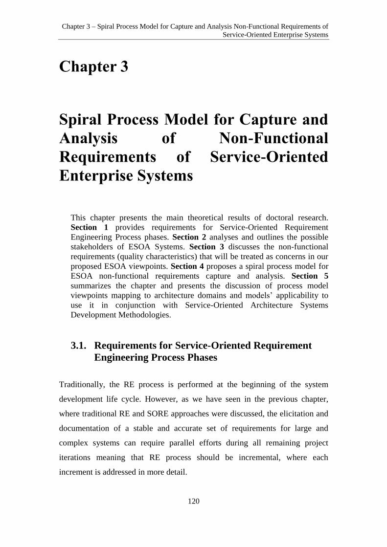
Chapter 3 – Spiral Process Model for Capture and Analysis Non-Functional Requirements of
Service-Oriented Enterprise Systems
120
Chapter 3
Spiral Process Model for Capture and
Analysis of Non-Functional
Requirements of Service-Oriented
Enterprise Systems
This chapter presents the main theoretical results of doctoral research.
Section 1 provides requirements for Service-Oriented Requirement
Engineering Process phases. Section 2 analyses and outlines the possible
stakeholders of ESOA Systems. Section 3 discusses the non-functional
requirements (quality characteristics) that will be treated as concerns in our
proposed ESOA viewpoints. Section 4 proposes a spiral process model for
ESOA non-functional requirements capture and analysis. Section 5
summarizes the chapter and presents the discussion of process model
viewpoints mapping to architecture domains and models’ applicability to
use it in conjunction with Service-Oriented Architecture Systems
Development Methodologies.
3.1. Requirements for Service-Oriented Requirement
Engineering Process Phases
Traditionally, the RE process is performed at the beginning of the system
development life cycle. However, as we have seen in the previous chapter,
where traditional RE and SORE approaches were discussed, the elicitation and
documentation of a stable and accurate set of requirements for large and
complex systems can require parallel efforts during all remaining project
iterations meaning that RE process should be incremental, where each
increment is addressed in more detail.

Chapter 3 – Spiral Process Model for Capture and Analysis Non-Functional Requirements of
Service-Oriented Enterprise Systems
121
In addition to this, a sophisticated RE process should cover at least SDLC RE
(Requirements Elicitation, Requirements Analysis, Requirements Verification,
Requirements Specification, Requirements Management) activities, provide
activities for Business Contextual Analysis, Communication and Requirement
Negotiation, Requirement Change Management and a RE Process Monitoring
Activity that will ensure that all RE process activities follow proper
procedures.
SOA offers a different architectural style of software systems and is a shift
from traditional development paradigms. As a result, it requires a new service-
oriented Requirement Engineering Process that would primary inherit all the
characteristics of a traditional sophisticated RE process (described in Chapter
2.1.2 Classic RE Process and Models) as well as add new ones aimed to solve
SORE challenges. Furthermore, SOA requirements are affected by both service
providers and customers, meaning that providers would try to design services
that can satisfy multiple customers, customers will be looking for services that
accommodate their needs and, if no exact match is found, they will have to
change their processes to conform to the services provided. As a result, SORE
must be capable of complying with all these issues. In addition, SORE should
provide an ability to discover services and workflows either at design time
(static SOA) or at runtime (dynamic SOA). Similarly, the ability to identify the
needed policy specification for execution control and management is also
required and SOA application should be able to discover such policies from the
policy pool either at design time or at runtime. Moreover, SORE should
consider dynamic SOA application rebinding and re-composition by choosing
different services, workflows, collaboration, and system architecture at
runtime.
Having this in mind, we propose a list of Service-oriented Requirements
Engineering Process phases that should be performed in an iterative manner
starting from:

Chapter 3 – Spiral Process Model for Capture and Analysis Non-Functional Requirements of
Service-Oriented Enterprise Systems
122
1. Contextual Analysis Phase where environmental influences (economic,
political and legal) which could affect the successful software system
development are investigated and discussed.
2. Business Process Modelling Phase where business goals and the
business processes that support those goals are identified making a high-
level model of the business processes. An initial set of business
requirements is derived from the organization’s set of business
processes (business model) and the organization’s service repository
(service model).
3. Service Identification Phase that requires a business focused viewpoint,
the involvement of a greater number of stakeholders and a well-
managed service repository. The main focus here is to identify the
services that match the system requirements. On the other hand, a
service-oriented RE not only has to identify what services are needed,
but should also provide assistance to adjust service-oriented software
system to changing business processes and business requirements. As a
result, the Service-oriented RE process should spread across the whole
service-oriented system development cycle and include two more
phases – Service Development and Service-oriented Systems
Development (Galster & Bucherer, 2008).
4. Service Development Phase is aimed at developing software
components for later use as services. This phase should focus on the
determination of requirements for individual services and the
specification of their interfaces to make service available for various
potential users or be used internally in a service-oriented system
development if a service is not going to be published.
5. Service-oriented Systems Development Phase is aimed at the (re)use and
orchestration or choreography of existing services. This phase should
focus on the identification of service candidates, their potential
compositions and workflows from the requirements, so that real services
could be composed during design-time or run-time. A service-oriented

Chapter 3 – Spiral Process Model for Capture and Analysis Non-Functional Requirements of
Service-Oriented Enterprise Systems
123
system should be able to adapt to changing user requirements by
changing dynamically its services, workflows, compositions, web
interfaces etc. This phase should cover service discoverability and
knowledge management activities.
6. Requirements Management and Requirements Change Management
Phase is aimed to propose advanced requirement managing capabilities
as it allows tracking all requirement changes and provides a requirement
change history for requirement traceability, auditing and continuous
improvement issues.
7. Requirement Process Monitoring Phase is an additional requirement
management process phase that allows monitoring and tracking all
previously named SORE phases in an attempt to ensure that they follow
proper procedures and are performed accurately.
3.2. Stakeholders of ESOA Systems
After proposing requirements for Service-Oriented Requirement Engineering
Process phases we decided to limit the scope of our research from the whole
SORE process to two phases – service identification and development and
especially to one type of issues – service specification issues with the aim to
design a process model for non-functional requirements capturing, analysis and
conflicts resolution using viewpoints. As we have seen from Chapter 2.3
Capturing Non-Functional Requirements for ESOA Systems Using
Viewpoints, each viewpoint frames a set of concerns of a group of
stakeholders. In this section, we will investigate the context of ESOA systems
and identify the key stakeholders typically participating in ESOA projects.
In software systems, stakeholders are persons or groups of people who are
supposed to influence the development of the system. In order to address
business requirements efficiently in ESOA development, all the key roles must
be identified as stakeholders from the beginning of the project. ESOA
stakeholders differ from traditional software systems stakeholders in a number

Chapter 3 – Spiral Process Model for Capture and Analysis Non-Functional Requirements of
Service-Oriented Enterprise Systems
124
of ways. Firstly, new service-oriented roles, tasks and responsibilities are
introduced. Secondly, ESOA projects require more governance as ESOA
initiative usually encompasses all enterprise and is not limited to a specific
project. For example, SOA GRM suggests service-oriented governance
stakeholder groups such as ESOA Steering Board, ESOA Governance Board in
addition to Business/IT Steering Group and EA Governance Board stakeholder
groups, which are usually established in traditional software development
projects. Moreover, ESOA initiatives require more experience and supervision.
As a result, a ESOA Centre of Excellence a stakeholder group is introduced by
SOA GRM. Furthermore, a separate Service Development Team is proposed to
develop services by one team and integrate (compose) them by another –
Solutions Development Team.
Stakeholders of a system have concerns in respect of the system-of-interest
considered in relation to its environment. Quality attributes of the ESOA
system in viewpoints can be reflected as concerns. A concern can be held by
one or more stakeholders. Concerns arise throughout the life cycle: from
system needs and requirements, from design choices and from implementation
and operating considerations. The role of an architect is to address these
concerns, by identifying and refining requirements that stakeholders have,
developing viewpoints of an architecture that show how concerns and
requirements are going to be addressed, and by showing the trade-offs that are
going to be made in reconciling the potentially conflicting concerns of
different stakeholders (Sommerville & Sawyer, 1997).
According to the standard (ISO/IEC/IEEE 42010:2011), the following
stakeholder groups should be considered and when applicable, identified in the
architecture description: users of the system, operators of the system, acquirers
of the system, owners of the system, suppliers of the system, developers of the
system, builders of the system, maintainers of the system.
The list of stakeholder groups for ESOA systems can typically include some or
all of the groups as follows (SOA GRM; TOGAF 9.1, 2011):

Chapter 3 – Spiral Process Model for Capture and Analysis Non-Functional Requirements of
Service-Oriented Enterprise Systems
125
Business/IT Steering Group (Sponsorship of all IT Solutions and Services):
CIO – Chief Information Officer, CTO or Chief IT Strategist, Chief Architect,
Business Domain Owners. Key concerns of this group are high-level drivers,
goals and objectives of an enterprise and how these are translated into an
effective process and IT architecture to advance the business. The main
artefacts for this group are a business footprint diagram, a
goal/objective/service diagram, and an enterprise decomposition diagram.
ESOA Steering Board (Sponsorship of ESOA Program and Leadership):
ESOA Chief Architect, ESOA Program Director, ESOA Business Sponsor.
Key concerns of this group are prioritizing, funding and aligning change
activity, an understanding of the project content and technical dependencies
between projects, support portfolio management and decision-making. The
main artefacts for this group are a requirements catalogue, project context
diagram, benefits diagram, business footprint diagram, application
communication diagram, and a functional decomposition diagram.
EA Governance Board (Informing and Monitoring): Chief Enterprise
Architect, Enterprise Architects, Chief ESOA Architect. Key concerns of this
group are ensuring the consistent governance of an enterprise application and
technology assets. The main artefacts for this group are a
process/event/control/product catalogue, application portfolio catalogue,
interface catalogue, technology standards catalogue and technology portfolio
catalogue.
ESOA Centre of Excellence (Definition and Development): Business
Champion, Chief ESOA Solution Architect, Organizational Change
Consultant, Test Strategist, Tool strategist. The key concerns of this group are
the high-level drivers, goals and objectives of an enterprise and how these are
translated into an effective ESOA to advance the business. In addition to this,
this group ensures that ESOA meets the service levels required by an enterprise
to succeed in business. The main artefacts for this group are a business
footprint diagram, goal/objective/service diagram, enterprise decomposition

Chapter 3 – Spiral Process Model for Capture and Analysis Non-Functional Requirements of
Service-Oriented Enterprise Systems
126
diagram, process flow diagram, application communication diagram,
process/application realization diagram, enterprise manageability diagram.
Business Domain Representatives (Scope and Delivery Management):
Program Manager, Business Architect, Process Engineer, Business Subject-
matter Expert. Key concerns of this group are functional aspects of processes
and supporting systems. This can cover the human actors involved in the
system, the user processes involved in the system, the functions required to
support the processes, and the information required to flow in support of the
processes. The main artefacts for this group are business interaction matrix,
actor/role matrix, business service/information diagram, functional
decomposition diagram, product lifecycle diagram, business use-case diagram,
application use-case diagram, application communication diagram, data
entity/business function matrix.
ESOA Governance Board (Informing and Monitoring): ESOA Chief
Architect, Business Architects. Key concerns of this group are quality
characteristics of ESOA such as the modifiability, re-usability and availability
of all services in ESOA, ensuring that the appropriate services are developed
and deployed within the system in an optimal manner. The main artefacts for
this group are a//the platform decomposition diagram, technology standards
catalogue, technology portfolio catalogue, enterprise manageability diagram,
networked computing/hardware diagram, processing diagram, environments
and locations diagram.
Solution Development Team (Execution and Delivery): Project Manager
Business Analysts, Solution Architects, Integration Specialist, Operations
Architect, Developers, Testers, Security Architect. The key concerns of this
group are refining business requirements designed by business domain
representatives group, preparing detailed requirements for Service
Development Team, integrating their developed services and testing them. The
main artefacts for this group are business interaction matrix, actor/role matrix,
business service/information diagram, functional decomposition diagram,
product lifecycle diagram, business use-case diagram, application use-case

Chapter 3 – Spiral Process Model for Capture and Analysis Non-Functional Requirements of
Service-Oriented Enterprise Systems
127
diagram, application communication diagram, data entity/business function
matrix, platform decomposition diagram, networked computing/hardware
diagram, software distribution diagram.
Service Development Team (Execution and Delivery): Project Manager
Business Analysts, Service Architects, Integration Specialist, Operations
Architect, Developers, Testers, Security Architects. The key concerns of this
group are refining service requirements designed by solution development
group, preparing detailed requirements (if required), developing services and
testing them. The main artefacts for this group are an actor/role matrix,
business service/information diagram, functional decomposition diagram,
product lifecycle diagram, business use-case diagram, application use-case
diagram, application communication diagram, data entity/business function
matrix, service description, platform decomposition diagram, networked
computing/hardware diagram, software distribution diagram.
IT Operations (Execution and Delivery): Database Administrator, Network
Infrastructure Architect, System Administrator, Service Operations Manager.
The key concerns of this group are deploying ESOA, ensuring that it is
available for use and accessible, ensuring that the appropriate communication
and networking services are developed and deployed within ESOA in an
optimal manner. The main artefacts for this group are a platform
decomposition diagram, technology standards catalogue, technology portfolio
catalogue, enterprise manageability diagram, networked computing/hardware
diagram, processing diagram, environments and locations diagram.
ESOA Consumers (Production): Users that directly interact with ESOA,
external systems, applications, services. The key concerns of this group are
usability and performance of ESOA. The main artefacts for this group are
ESOA change requests.
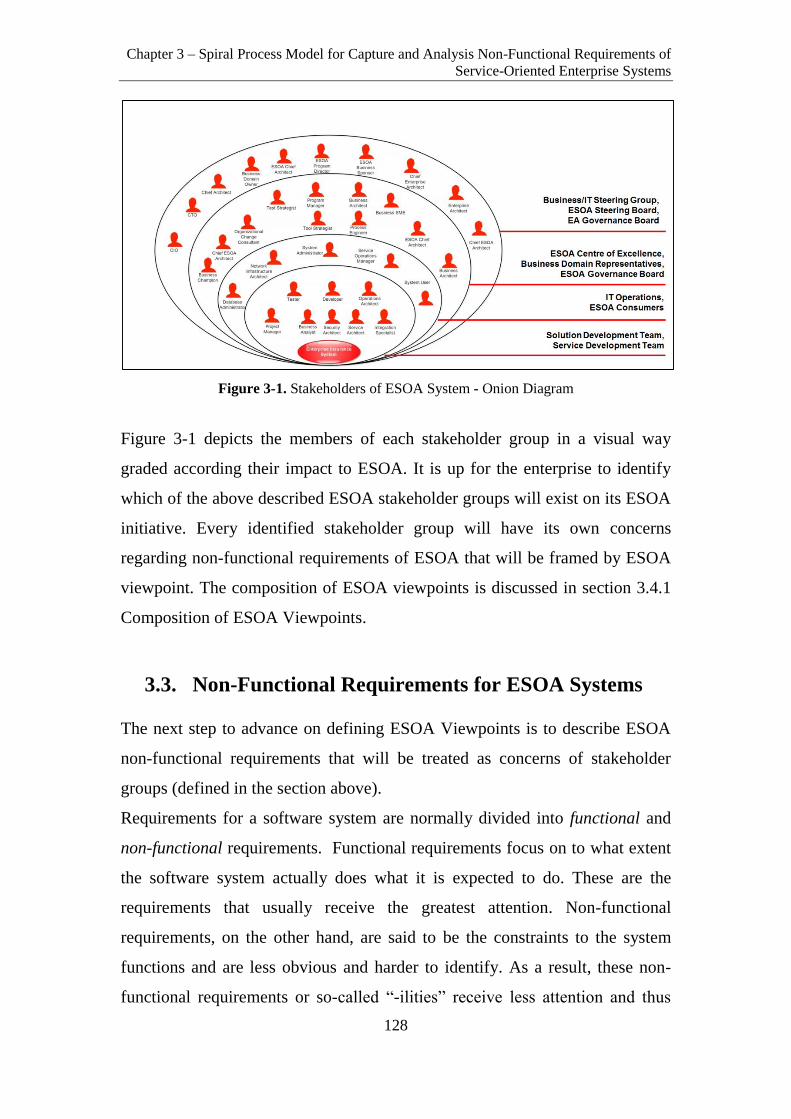
Chapter 3 – Spiral Process Model for Capture and Analysis Non-Functional Requirements of
Service-Oriented Enterprise Systems
128
Figure 3-1. Stakeholders of ESOA System - Onion Diagram
Figure 3-1 depicts the members of each stakeholder group in a visual way
graded according their impact to ESOA. It is up for the enterprise to identify
which of the above described ESOA stakeholder groups will exist on its ESOA
initiative. Every identified stakeholder group will have its own concerns
regarding non-functional requirements of ESOA that will be framed by ESOA
viewpoint. The composition of ESOA viewpoints is discussed in section 3.4.1
Composition of ESOA Viewpoints.
3.3. Non-Functional Requirements for ESOA Systems
The next step to advance on defining ESOA Viewpoints is to describe ESOA
non-functional requirements that will be treated as concerns of stakeholder
groups (defined in the section above).
Requirements for a software system are normally divided into functional and
non-functional requirements. Functional requirements focus on to what extent
the software system actually does what it is expected to do. These are the
requirements that usually receive the greatest attention. Non-functional
requirements, on the other hand, are said to be the constraints to the system
functions and are less obvious and harder to identify. As a result, these non-
functional requirements or so-called “-ilities” receive less attention and thus

Chapter 3 – Spiral Process Model for Capture and Analysis Non-Functional Requirements of
Service-Oriented Enterprise Systems
129
become more critical. Despite this, or more likely, because of this, the non-
functional attributes describing the technical aspects of software systems have
been defined by multiple different organisations and companies, such as the
International Standards Organization - ISO and International Electrotechnical
Commission – IEC with the report ISO/IEC 9126 (ISO/IEC 9126:2000) later
revised by ISO/IEC 25010:2011 (ISO/IEC 25010:2011), IBM with
CUPRIMDSO (Kan, 2002) and Hewlett Packard with FURPS (Grady, 1987).
Non-functional requirements for ESOA systems are inherited from traditional
software systems. The main difference lies in the definition of quality attribute
and its metrics. In traditional software systems requirements engineering
quality attributes are defined in a more generic way and usually concern the
characteristics of the whole system. For example, availability non-functional
requirement in standard (ISO/IEC 25010:2011) is defined as a “degree to
which a system, product or component is operational and accessible when
required for use”. Some of the metrics for this attribute are mean time between
failure (MTBF) and mean time to recover (MTTR). On the contrary, in ESOA
world quality attributes can be defined in a more specific way and are limited
to measuring the characteristic of a specific service. The same availability
attribute in (O'Brien et al., 2005; Choi et al., 2007) is defined as a “quality
attribute that measures the degree to which a service is accessible and
operational when service consumer requests for use”. The metrics for this
attribute in ESOA suggested by (Choi et al., 2007) are the availability of
business process (ABP) and the availability of web service (AWS). Generally,
in ESOA the quality of service is hidden from service consumers due to the
black-box nature of ESOA. In a service composition, the low quality of an
atomic service may cause the quality degradation of all its successors in a
service composition. As a result, non-functional requirements relate to the
desired characteristics of a given service running independently and also while
being integrated with other services at run-time.
The choice to use an ESOA approach depends on several factors including the
architecture’s ultimate ability to meet functional and non-functional

Chapter 3 – Spiral Process Model for Capture and Analysis Non-Functional Requirements of
Service-Oriented Enterprise Systems
130
requirements. Usually, architecture needs to satisfy many non-functional
requirements in order to achieve enterprise business goals. Researches by
(O'Brien et al., 2005; Choi et al., 2007) suggest defining ESOA non-functional
requirements by identifying unique features (principles) of ESOA such as loose
coupling, well-defined service contract, standard-based, abstraction,
reusability, discoverability, composability, adaptability, service interface level
abstraction and mapping those features to quality attributes. In almost all cases,
trade-offs have to be made between these requirements. As a consequence,
each of the ESOA stakeholder group (defined in the section above) will be
concerned in one or more quality attributes provided in the sections below
(O'Brien et al., 2005; Choi et al., 2007).
3.3.1. Availability
This quality attribute measures the degree to which a service is accessible and
operational when service consumer requests for use (O'Brien et al., 2005).
Availability of services both from the user’s and provider’s perspective is a
concern for the success of ESOA. From the services user’s perspective, if the
system relies on a set of services being available in order to meet its functional
requirements and one of those services becomes unavailable, it could have dire
consequences on ESOA. From the service provider’s perspective, in order for
the services to be used, they must be available when needed. Otherwise, the
provider’s finances and reputation could be impacted.
Service providers usually agree to provide the service users a set of services
and to include each service in an SLA. The SLA defines the contract for the
provision of the service with details such as who provides the service, the
guaranteed availability of the service, the escalation process (which is followed
if the service is not handled to the service user’s satisfaction), and the penalties
to the provider if the service level is not met. Usually, both the provider and
user offer some form of capability for monitoring service availability.
Furthermore, service users who build systems that rely on particular services
being available must build contingencies (such as exception handling) into

Chapter 3 – Spiral Process Model for Capture and Analysis Non-Functional Requirements of
Service-Oriented Enterprise Systems
131
those systems, in case the services become unavailable. For example, the
application could find an alternative provider for a service.
Research by (Choi et al., 2007) suggests two metrics for availability of service
depending on service type.
For an atomic service that is realized as web service, the metric is
Availability of Web Service – AWS. It can be calculated using the
following formula:
𝐴𝑊𝑆 = 𝑊𝑆𝑂𝑇
𝑊𝑆𝑂𝑇 + 𝑊𝑆𝑅𝑇
WSOT means web service operating time which is derived from the web
service starting time and the web service ending time. WSRT means web
service repairing time which is derived from the web service failed time and
the web service recovered time. The range of AWS is 0...1 where a higher value
indicates higher availability of the web service.
For a composite service that is realized as business process, the metric
is Availability of Business Process – ABP. It can be calculated using the
following formula:
𝐴𝐵𝑃 =𝐵𝑃𝑂𝑇
𝐵𝑃𝑂𝑇 + 𝐵𝑃𝑅𝑇
BPOT means business process operating time which is derived from the
business process starting time and the business process ending time. BPRT
means business process repairing time which is derived from the business
process failed time and the business process recovered time. The range of ABP
is 0...1 where a higher value indicates higher availability of the business
process.
3.3.2. Performance
This quality attribute measures the capability of the service to provide
appropriate response and processing times and throughput rates when
performing its function, under stated conditions (O'Brien et al., 2005).
Performance is an important factor not only for a service consumer but also for

Chapter 3 – Spiral Process Model for Capture and Analysis Non-Functional Requirements of
Service-Oriented Enterprise Systems
132
a service provider because services are generally located in a distributed
computing environment (in ESOA we still can have integrations with third-
party services) and can have heavy performance to interoperate between
heterogeneous services. As a result, this quality attribute affects service
selection and is an essential criterion to assess conformance to service level
agreement.
In general, this quality attribute is related to response time (how long it takes to
process a request), throughput (how many requests overall can be processed
per unit of time), or timeliness (ability to meet deadlines, i.e., to process a
request in a deterministic and acceptable amount of time).
Research by (Choi et al., 2007) suggests several metrics for measuring service
performance.
Service Response Time – SRT metric is an elapsed time between the end of a
request to a service and the beginning of the service’s response. It can be
calculated as:
SRT = Time when Service Consumer finishes sending request to the Service –
Time when Service Consumer starts receiving response from the Service.
This metric can be applied to both the atomic service and composite service.
The range of SRT is SRT > 0, where a lower value indicates higher response
time of the service.
Furthermore, SRT can be broken down into four components: transmission
time, setup time, waiting time, and processing time.
1. Transmission time is the time spent for communicating over the
network;
2. Setup time is the time spent for setting up the service instance to be
executed. The setup time can be further broken down into XML message
processing time, discovery time, adaptation time, and composition time.
a. XML message processing time is the time spent in parsing,
validating, and transforming XML document;
b. Discovery time is the time spent for dynamically finding the
required services;

Chapter 3 – Spiral Process Model for Capture and Analysis Non-Functional Requirements of
Service-Oriented Enterprise Systems
133
c. Adaptation time is the time spent for dynamically adapting the
service to satisfy the consumer’s expectation;
d. Composition time is the time spent for dynamically composing a
set of atomic services.
3. Waiting time is the time spent for a service instance to wait in the ready
queue before processing;
4. Processing time is the time a service instance spends performing its
intended activity.
Breaking SRT into various pieces is important as it gives a more detailed view
to be used in performance analysis. Each piece corresponds to an important
attribute that needs to be analysed and should not be overlooked.
Throughput represents the number of requests served at a given period of time.
TP(SRV) for the throughput of a service can be calculated using the following
formula:
𝑇𝑃 (𝑆𝑅𝑉) =𝑁𝑢𝑚𝑏𝑒𝑟 𝑜𝑓 𝑆𝑢𝑐𝑐𝑒𝑠𝑠𝑓𝑢𝑙𝑙𝑦 𝐶𝑜𝑚𝑝𝑙𝑒𝑡𝑒𝑑 𝑆𝑒𝑟𝑣𝑖𝑐𝑒 𝑅𝑒𝑞𝑢𝑒𝑠𝑡𝑠
𝑈𝑛𝑖𝑡 𝑜𝑓 𝑇𝑖𝑚𝑒 (𝑒. 𝑔. 𝑠𝑒𝑐𝑜𝑛𝑑, 𝑚𝑖𝑛𝑢𝑡𝑒, ℎ𝑜𝑢𝑟)
This metric can be applied to both the atomic service and composite service.
The value range of the metric is TP(SRV) > 0. The higher the value is, the
better the performance.
3.3.3. Reliability
This quality attribute measures the ability of a service to keep operating with
specified level of performance over time (O'Brien et al., 2005). The reason for
defining this attribute is that services are reusable and are used in various
compositions. A service composition which is composed of several services
operating in heterogonous and distributed computing environment, one atomic
service may affect the reliability of the whole service composition by
unexpected faults or failures.
There are several aspects of reliability, particularly the reliability of the
messages that are exchanged between the services, and the reliability of the

Chapter 3 – Spiral Process Model for Capture and Analysis Non-Functional Requirements of
Service-Oriented Enterprise Systems
134
services themselves. Applications developed by different organizations may
have different reliability requirements for the same set of services. And an
application that operates in different environments may have different
reliability requirements in each one.
Services are often made available over a network with possibly unreliable
communication channels. Connections break and messages fail to get delivered
or are delivered more than once or in the wrong sequence. Although techniques
for ensuring the reliable delivery of messages are reasonably well understood
and available in some messaging middleware products today, messaging
reliability is still a problem. If reliability is addressed by service developers
who are incorporating reliability techniques directly into the services and
application, there is no guarantee that they will make consistent choices about
what approach to adopt. The outcome might not guarantee end-to-end reliable
messaging. Even in cases in which the application developers defer dealing
with the reliable messaging to messaging middleware, different middleware
products from different vendors do not necessarily offer a consistent approach
to dealing with the problem. The use of middleware from different vendors
might preclude reliable message exchange between applications and services
that are using different message-oriented middleware (Weerawarana et al,
2005).
Service reliability means the service either does not fail or reports failure to the
service user. Service reliability also means making sure that the service is
obtained from a reliable provider so that a level of trust in the service’s
accuracy and reliability can be established. Issues that have to be dealt with
include managing the transactional context, for example, dealing with failures
or some form of compensation if the service fails. In some cases, brokers or
intermediaries may link the service users and providers. As a result, these
issues may be handled by third parties.
ESOA can guarantee a high level of reliability through the architecture i.e.
through its Enterprise Service Bus – ESB. ESB provides reliability through its
good capability of assuring that the requests from service consumers are

Chapter 3 – Spiral Process Model for Capture and Analysis Non-Functional Requirements of
Service-Oriented Enterprise Systems
135
transferred to providers, i.e. assuring the transportation of messaging
(Bieberstein et al, 2006).
Research by (Choi et al., 2007) suggests several metrics for measuring service
reliability:
Reliable Response Ratio (RRR) – a metric based on discrete time
modelling approach. Metric measures the ratio of how many responses
are reliable among the total request. It can be calculated with the
following formula:
𝑅𝑅𝑅 = 𝑁𝑢𝑚𝑏𝑒𝑟 𝑜𝑓 𝑅𝑒𝑙𝑖𝑎𝑏𝑙𝑒 𝑅𝑒𝑠𝑝𝑜𝑛𝑠𝑒𝑠
𝑇𝑜𝑡𝑎𝑙 𝑁𝑢𝑚𝑏𝑒𝑟 𝑜𝑓 𝑅𝑒𝑞𝑢𝑒𝑠𝑡𝑠
The value range of RRR is 0...1. The higher value indicates a better
reliable response ratio.
Service Failure Ratio (SFR) and Mean Time Between Service Failure –
MTBF(SRV) – metrics based on continuous-time modelling approach.
SFR metric measures the ratio of how many services failed during a
specific time interval. It can be calculated with the following formula:
𝑆𝐹𝑅 =𝑁𝑢𝑚𝑏𝑒𝑟 𝑜𝑓 𝐹𝑎𝑖𝑙𝑢𝑟𝑒𝑠
𝑇𝑖𝑚𝑒 𝑃𝑒𝑟𝑖𝑜𝑑
The value range of SFR is SFR ≥ 0. The lower value indicates a better
reliable service.
MTBF(SRV) metric indicates the average time between consecutive
service failures. It can be calculated with the following formula:
𝑀𝑇𝐵𝐹 (𝑆𝑅𝑉) =𝑆𝑢𝑚𝑚𝑎𝑡𝑖𝑜𝑛 𝑜𝑓 𝑇𝑖𝑚𝑒 𝐵𝑒𝑡𝑤𝑒𝑒𝑛 𝐹𝑎𝑖𝑙𝑢𝑟𝑒𝑠
𝑇𝑜𝑡𝑎𝑙 𝑁𝑢𝑚𝑏𝑒𝑟 𝑜𝑓 𝐹𝑎𝑖𝑙𝑢𝑟𝑒𝑠
The value range of this metric is MTBF(SRV) > 0 where the higher
value indicates better reliability.
3.3.4. Usability
This quality attribute measures the capability of a service to be effectively
understood, learned and used by the service consumer (O'Brien et al., 2005).
The rationale for defining this quality attribute is that if the service provides a

Chapter 3 – Spiral Process Model for Capture and Analysis Non-Functional Requirements of
Service-Oriented Enterprise Systems
136
high degree of well-defined service contract then the service consumers can
more effectively understand and use the services. And since the services are
black box in nature to the service consumer the service contract is the only
mean to understand services.
Research by (Choi et al., 2007) suggests two metrics for measuring service
usability:
Syntactic Completeness of Service Interface (SynCSI)
𝑆𝑦𝑛𝐶𝑆𝐼 =𝑊𝑒𝑙𝑙 𝐷𝑒𝑠𝑐𝑟𝑖𝑏𝑒𝑑 𝑆𝑦𝑛𝑡𝑎𝑐𝑡𝑖𝑐 𝐸𝑙𝑒𝑚𝑒𝑛𝑡𝑠
𝑇𝑜𝑡𝑎𝑙 𝑁𝑢𝑚𝑏𝑒𝑟 𝑜𝑓 𝑆𝑦𝑛𝑡𝑎𝑐𝑡𝑖𝑐 𝐸𝑙𝑒𝑚𝑒𝑛𝑡𝑠 𝑖𝑛 𝑊𝑆𝐷𝐿
The syntactic elements indicate contents of tags related to signature of
service operations. Well described means the contents that are easily
and concisely described. The value range of SynCSI is 0…1. The higher
value indicates a better usable ratio.
Semantic Completeness of Service Interface (SemCSI)
𝑆𝑒𝑚𝐶𝑆𝐼 =𝑊𝑒𝑙𝑙 𝐷𝑒𝑠𝑐𝑟𝑖𝑏𝑒𝑑 𝑆𝑒𝑚𝑎𝑛𝑡𝑖𝑐 𝐸𝑙𝑒𝑚𝑒𝑛𝑡𝑠
𝑇𝑜𝑡𝑎𝑙 𝑁𝑢𝑚𝑏𝑒𝑟 𝑜𝑓 𝑆𝑒𝑚𝑎𝑛𝑡𝑖𝑐 𝐸𝑙𝑒𝑚𝑒𝑛𝑡𝑠 𝑖𝑛 𝑊𝑆𝐷𝐿
The semantic elements indicate contents of tags related to semantic
information of service operation such as pre condition, post condition,
output constraints, effect, service category, and description of service
operation. The value range of SemCSI is 0…1. The higher value
indicates a better usable ratio.
The completeness in metrics means how many service operations are well
described in the service interface.
Furthermore, we can acquire the value of usability by combining the metrics,
SynCSI and SemSCI with Completeness of Service Interface (CSI) metric.
𝐶𝑆𝐼 = 𝑊𝑆𝑦𝑛 × 𝑆𝑦𝑛𝐶𝑆𝐼 + 𝑊𝑆𝑒𝑚 × 𝑆𝑒𝑚𝐶𝑆𝐼
WSyn is the weight for SynCSI and WSem is the weight for SemCSI. The sum of
the weights is 1.

Chapter 3 – Spiral Process Model for Capture and Analysis Non-Functional Requirements of
Service-Oriented Enterprise Systems
137
3.3.5. Discoverability
This quality attribute measures the capability of the service to be easily,
accurately, and suitably found at both design time and runtime for the required
service specification (O'Brien et al., 2005). In ESOA, services are located in
loosely coupled environment and the services should be addressable over the
network. Consumers find services from the service registry to be provided with
their expected functionality. And for the dynamic composition, services should
be discoverable at runtime. Otherwise, goals achieved through dynamic
composition in SOA may not be offered.
Research by (Choi et al., 2007) suggests several metrics for measuring service
discoverability. Discoverability of the service itself can be measured by the
CSI usability metric defined above since the service has to be well described to
be effectively discovered. However, discoverability of a service highly
depends on the capability of a discovery agent. Therefore, we define two
additional metrics to measure discoverability of the discovery agent:
Interface Find Ratio – IFR measures the ratio of how many interfaces
are discovered. It can be calculated with the following formula:
𝐼𝐹𝑅 =𝑁𝑢𝑚𝑏𝑒𝑟 𝑜𝑓 𝐼𝑛𝑡𝑒𝑟𝑓𝑎𝑐𝑒𝑠 𝐷𝑖𝑠𝑐𝑜𝑣𝑒𝑟𝑒𝑑
𝑇𝑜𝑡𝑎𝑙 𝑁𝑢𝑚𝑏𝑒𝑟 𝑜𝑓 𝐼𝑛𝑡𝑒𝑟𝑓𝑎𝑐𝑒𝑠 𝑡𝑜 𝐷𝑖𝑠𝑐𝑜𝑣𝑒𝑟
The numerator is the number of interfaces discovered that syntactically
matches to the required interfaces. The denominator is the total number of
interfaces that the consumer expects to discover. The value range of IFR is
0…1 where the higher value indicates higher discoverability.
Interface Find Accuracy – IFA measures the ratio of how many well
matched interfaces are discovered. This metric can be calculated with
the following formula:
𝐼𝐹𝐴 =𝑁𝑢𝑚𝑏𝑒𝑟 𝑜𝑓 𝐴𝑝𝑝𝑟𝑜𝑝𝑟𝑖𝑎𝑡𝑒 𝐼𝑛𝑡𝑒𝑟𝑓𝑎𝑐𝑒𝑠
𝑁𝑢𝑚𝑏𝑒𝑟 𝑜𝑓 𝐼𝑛𝑡𝑒𝑟𝑓𝑎𝑐𝑒𝑠 𝐷𝑖𝑠𝑐𝑜𝑣𝑒𝑟𝑒𝑑

Chapter 3 – Spiral Process Model for Capture and Analysis Non-Functional Requirements of
Service-Oriented Enterprise Systems
138
The numerator is the number of interfaces that matches not only syntactically
but also semantically. The value range of IFA is 0..1 where the higher value
indicates higher discoverability.
DisCoverability – DC is metric derived by multiplying IFR and IFA
that measures syntactic and semantic interface discoverability.
𝐷𝐶 =𝑁𝑢𝑚𝑏𝑒𝑟 𝑜𝑓 𝐴𝑝𝑝𝑟𝑜𝑝𝑟𝑖𝑎𝑡𝑒 𝐼𝑛𝑡𝑒𝑟𝑓𝑎𝑐𝑒𝑠
𝑇𝑜𝑡𝑎𝑙 𝑁𝑢𝑚𝑏𝑒𝑟 𝑜𝑓 𝐼𝑛𝑡𝑒𝑟𝑓𝑎𝑐𝑒𝑠 𝑡𝑜 𝐷𝑖𝑠𝑐𝑜𝑣𝑒𝑟
The value range of DC is 0…1 where the higher value indicates higher
discoverability.
3.3.6. Adaptability
This quality attribute measures the capability of the service to be feasibly
adapted at both design time and runtime for different consumer’s preference
and service context information (O'Brien et al., 2005). The rationale for
defining this attribute is that reusing service is one of the main advantages that
ESOA delivers. For the services to be reused widely, a published service
should be adaptable to various service requirements and contexts.
Adaptability means the ease with which a system may be changed to fit
changed requirements. Adaptability for a business means it can adapt quickly
to new opportunities and potential competitive threats, which implies that the
application development and maintenance groups within the business can
quickly change the existing systems. The use of an ESOA approach brings
various benefits to the ability to adapt by allowing the following:
Services can be built and deployed using the principles of location and
transport independence and declarative policy. As a result, service users
can dynamically discover and negotiate the method to be used for
binding and the behaviour to be exhibited for interacting with a service.
If the service needs to adapt, this discovery and binding should be
automated and not require a change in the application.
Business processes that are modelled using services can be adapted,
and those services can be combined in new and different ways.

Chapter 3 – Spiral Process Model for Capture and Analysis Non-Functional Requirements of
Service-Oriented Enterprise Systems
139
Additional services can be added, or adapted services can be swapped
in where needed. What will require changes is the underlying
application using these services.
Services are being developed that must operate on different platforms,
in different computing environments. These services must be
“configurable” to the environment in which they will reside – a
significant adaptation challenge that requires “spiral” development with
incremental deliveries to particular platforms, interoperability between
different platforms, and backwards compatibility to multiple previous
releases. To achieve adaptability, the services will need to be managed
and monitored properly as a single cohesive solution, and the
interaction between the service and the underlying infrastructure will
have to be managed.
Adaptability of a service is measured in terms of internal adaptability and
external adaptability (Choi et al, 2007).
Internal adaptability measures whether the internal service variability
can be well adapted as the service consumer’s need. Let n be the
number of variation points – VPs in a service. For each VP, the variant
that the service consumer expects may be prepared or not. We indicate
this property of a VP as Variant Preparedness, which can have “yes” or
“no” value. If the default value of a VP satisfies the consumer’s
expectation, we also regard it as a prepared VP. A metric Variant
Coverage – VC measures how many VPs can be adapted as the
consumer wants them to be.
𝑉𝐶 =𝑁𝑢𝑚𝑏𝑒𝑟 𝑜𝑓 𝐴𝑑𝑎𝑝𝑡𝑒𝑑 𝑉𝑃𝑠
𝑇𝑜𝑡𝑎𝑙 𝑁𝑢𝑚𝑏𝑒𝑟 𝑜𝑓 𝑉𝑃𝑠
The range of VC is 0...1 where the higher value indicates higher
internal adaptability.
External adaptability measures if the external service mismatch is well
resolved to meet the service consumer’s requirement. Let m to be the
number of mismatches for a service. For each mismatch, the mismatch

Chapter 3 – Spiral Process Model for Capture and Analysis Non-Functional Requirements of
Service-Oriented Enterprise Systems
140
may be resolved or not. We indicate this as a Mismatch Resolvedness,
which can have “yes” or “no” value. A metric Mismatch Resolution
Rate – MR measures how many mismatches can be resolved.
𝑀𝑅 =𝑁𝑢𝑚𝑏𝑒𝑟 𝑜𝑓 𝑅𝑒𝑠𝑜𝑙𝑣𝑒𝑑 𝑀𝑖𝑠𝑚𝑎𝑡𝑐ℎ𝑒𝑠
𝑇𝑜𝑡𝑎𝑙 𝑁𝑢𝑚𝑏𝑒𝑟 𝑜𝑓 𝑀𝑖𝑠𝑚𝑎𝑡𝑐ℎ𝑒𝑠
The range of MR is 0...1 where the higher value indicates higher
external adaptability.
Adaptability – AD – metric derived by multiplying VC and MR that
measures internal and external service adaptability.
𝐴 = 𝑊𝑉𝐶 × 𝑉𝐶 + 𝑊𝑀𝑅 × 𝑀𝑅
WVC and WMR are the weights for VC and MR. The sum of weights is 1.
The value of each weight can be decided in the range of 0...1 according
to the adaptation mechanism used in the service.
3.3.7. Composability
This quality attribute measures the capability of a service to be well composed
to other services or a service composition to operate successfully by
composing atomic services (O'Brien et al., 2005). The reason for defining this
attribute is that one of the major goals of ESOA is to rapidly deliver the user’s
requirement by just composing the published services at runtime. And if the
composability is high, it turns out to be the services have high reusability, have
well defined service contract and are based on standard.
Composability is a composite attribute that is derived from other quality
attributes (Figure 3–2).
Chapter 3 – Spiral Process Model for Capture and Analysis Non-Functional Requirements of
Service-Oriented Enterprise Systems
141
Figure 3-2. Sub-Attributes of Composability (Choi et al, 2007)
Let there to be a composite service that consists of n atomic services and m
relationships among atomic services. Then composability of a composite
service is derived from the availability, discoverability, and adaptability of the
atomic services, validity and adaptability of the composition rule, and
interoperability of the relationships among atomic services (Choi et al, 2007).
Each atomic service composing the composite service has to be available,
some atomic services should be newly discoverable, and some should be
adaptable to be well composed into a composite service. These relationships
are represented as the aggregation relationship and multiplicities in the figure.
Through the atomic service evaluation, it can be identified where the
composition problem has occurred due to the operability of the services
participating in the composition. As the atomic services are composed
dynamically at runtime, composition rule defines how to configure the
services. This composition rule is defined for each dynamically configured
service composition. Therefore, composition rule should be valid and
adaptable for successful composition. These are measured by the following
metrics:
Validity of Composition Rule – VCR. This metric can be calculated
using the following formula:

Chapter 3 – Spiral Process Model for Capture and Analysis Non-Functional Requirements of
Service-Oriented Enterprise Systems
142
𝑉𝐶𝑅 =𝑁𝑢𝑚𝑏𝑒𝑟 𝑜𝑓 𝑉𝑎𝑙𝑖𝑑 𝐶𝑜𝑚𝑝𝑜𝑠𝑖𝑡𝑖𝑜𝑛𝑠
𝑇𝑜𝑡𝑎𝑙 𝑁𝑢𝑚𝑏𝑒𝑟 𝑜𝑓 𝐶𝑜𝑚𝑝𝑜𝑠𝑖𝑡𝑖𝑜𝑛𝑠
The value range of the metric is 0...1 where the higher value indicates
better validity that leads to higher composability.
Adaptability of Composition Rule – ACR. This metric can be calculated
using the following formula:
𝐴𝐶𝑅 =𝑁𝑢𝑚𝑏𝑒𝑟 𝑜𝑓 𝐴𝑑𝑎𝑝𝑡𝑒𝑑 𝑉𝑃𝑠
𝑇𝑜𝑡𝑎𝑙 𝑁𝑢𝑚𝑏𝑒𝑟 𝑜𝑓 𝑉𝑃𝑠 𝑖𝑛 𝐶𝑜𝑚𝑝𝑜𝑠𝑖𝑡𝑖𝑜𝑛 𝑅𝑢𝑙𝑒
The value range of the metric is 0…1 where the higher value indicates
higher adaptability. However, higher adaptability does not indicate
higher composability due to the complexity problem.
InterOperability – IO measures the ability of a service to interact with
other services without incompatibility. Therefore, interoperability
measures how often data can be exchanged successfully between
adjacent services.
𝐼𝑂 =𝑁𝑢𝑚𝑏𝑒𝑟 𝑜𝑓 𝑆𝑢𝑐𝑐𝑒𝑠𝑠𝑓𝑢𝑙 𝐷𝑎𝑡𝑎 𝐸𝑥𝑐ℎ𝑎𝑛𝑔𝑒𝑠
𝑇𝑜𝑡𝑎𝑙 𝑁𝑢𝑚𝑏𝑒𝑟 𝑜𝑓 𝐷𝑎𝑡𝑎 𝐸𝑥𝑐ℎ𝑎𝑛𝑔𝑒𝑠
The value range of the metric is 0…1 where the higher value indicates
higher interoperability that leads to higher composability.
ComPosability – CP can be acquired by combining these metrics as the
following:
𝐶𝑃 = 𝑊𝐴𝑆 × ∑ ( 𝑊𝐴𝑊𝑆 × 𝐴𝑊𝑆𝑖 + 𝐴𝐷𝐶 × 𝐷𝐶𝑖 + 𝐴𝐴𝐷 × 𝐴𝐷𝑖)𝑛
𝑖=1
𝑛
+ 𝑊𝐶𝑅 × (𝑊𝑣𝑎𝑙 × 𝑉𝐶𝑅 + 𝑊 𝑎𝑑𝑎𝑝𝑡 × 𝐴𝐶𝑅) + 𝑊𝑅
× ∑ 𝐼𝑂𝑗
𝑛𝑗=1
𝑚
Where n is the number of atomic services composing the composite service
and m is the number of relationships. And there is one composition rule for a
service composition. WAWS, ADC, and AAD are the weights for AWS, DC, and AD
of the services participating in the composition. Wval and WAdapt are the weights
for VCR and ACR where the sum is 1. They can be decided by the evaluator
according to the need of adaptation of the composition rule. WAS, WCR and WR

Chapter 3 – Spiral Process Model for Capture and Analysis Non-Functional Requirements of
Service-Oriented Enterprise Systems
143
are the weights for the properties of atomic services, composition rule, and
relationships among atomic services. The value range of CP is 0…1 where the
higher value indicates better composability.
3.3.8. Interoperability
This quality attribute refers to the ability of a collection of communicating
entities to share specific information and operate on it according to an agreed-
upon operational semantics (O'Brien et al., 2005). Increased interoperability is
the most prominent benefit of ESOA, especially when we consider Web
services technology. Distributed systems have been developed using various
languages and platforms that vary from portable devices to mainframes. They
have used technologies such as the Common Object Request Broker
Architecture – CORBA (WEB, m), Remote Method Invocation – RMI (WEB,
n), Distributed Component Object Model – DCOM (WEB, o), Remote
Procedure Call - RPC (WEB, p), and sockets for communication. However,
until the advent of Web services, there was no standard communication
protocol or data format that could be used effectively by systems using
different technologies to interoperate on a worldwide scale.
Today, mainstream development platforms such as Microsoft .NET (WEB, r)
and Oracle Java 2 Enterprise Edition – J2EE (WEB, s) – provide frameworks
to implement Web services. Components implemented in disparate platforms
using different languages can interact transparently through a call-and-return
mechanism. That is possible because Web services define the interface format
and communication protocols but do not restrict the implementation language
or platform. However, the promise of cross-vendor and cross-platform
interoperability in Web services begins to fall short when services start to use
features beyond the basic Web Service Definition Language – WSDL (WEB, t)
and Simple Object Access Protocol – SOAP (WEB, u) standards. Over the last
few years, a myriad of Web services standards (e.g., Web Services Business
Process Execution Language – WS-BPEL (WEB, v), WS-Security (WEB, w),

Chapter 3 – Spiral Process Model for Capture and Analysis Non-Functional Requirements of
Service-Oriented Enterprise Systems
144
and ebXML (WEB, x)) has emerged from a number of standards bodies. Web
services development platforms do not implement the same standards and the
same versions, so interoperability may not be as seamless in practice as it is in
theory.
Recognizing that reality, the Web Services Interoperability Organization –
WS-I (WEB, y) was chartered in 2002 to promote the interoperability of Web
services across platforms, applications, and programming languages. WS-I
(WEB, z) publishes profiles that prescribe adherence to a group of specific
versions of well-defined standards. Another goal of WS-I is to provide tools to
certify conformance with those profiles. The WS-I initiative has grabbed
considerable attention in the industry through its 130 (approximately) member
organizations, including Web services platform vendors (e.g., IBM, Microsoft,
BEA, Oracle, and Sun). Many Web service products were updated in recent
years because of this initiative. WS-I (WEB, z) has created a few profiles and
other deliverables but still has a lot of work to do to cover all layers and
standards in the Web services stack. Since the major benefit of Web services is
interoperability, the success of this initiative will determine the success of Web
services. The past has shown that the existence of published standards is not
sufficient to ensure interoperability across platforms from different vendors.
3.3.9. Security
This quality attribute denotes different things with respect to software systems.
In general, it is associated with three principles: confidentiality, authenticity,
information integrity (O'Brien et al., 2005). Security is a major concern for
SOA as well as ESOA and Web services. Architects should pay attention to
some characteristics that are inherent to (ESOA and directly impact security:
• Messages often contain data in text format (e.g., XML), and, even worse,
metadata is embedded. That means that someone intercepting a message
may clearly see a 16-digit number as well as metadata revealing that the

Chapter 3 – Spiral Process Model for Capture and Analysis Non-Functional Requirements of
Service-Oriented Enterprise Systems
145
number is the value of a credit card field. Encryption must be in place to
preserve privacy.
• A system built using ESOA approach may encompass services provided
by third-party organizations. Trust must be built into the security of such
external services. The identity of the external service provider has to be
authenticated, but sometimes authentication is not enough. Building trust
may involve other concerns. For instance, if the system sends classified
data to the external service, the data should be protected not only when it
is transmitted but also when it is stored.
• Services may have access restrictions based on the identity of the service
user. In that case, an authorization mechanism should be in place that
allows configuring and enforcing permissions to be set to specific users,
groups of users, or roles. An SOA solution may rely on looking up
services in a public directory. It is important to ensure that information in
the directory is up to date and was added by valid publishers. Web
services solutions have been addressing some of the security concerns at
the network infrastructure level. For example, Web servers that host Web
services can be configured to use Secure Sockets Layers – SSLs (WEB,
aa) and digital certificates to encrypt data transmission and authenticate
the communicating parties. In intranet solutions, Kerberos (WEB, ab) is
an option – users receive a ticket for access to each Web service they have
permission to use. However, these solutions merely help to protect point-
to-point interaction: a comprehensive mechanism that covers end-to-end
security is required.
In 2002, IBM, Microsoft, and VeriSign proposed Web Services Security
(WEB, w) as a comprehensive security model for Web services. The WS-
Security specification was submitted to OASIS, and the first version of the
standard was approved in 2004 (WEB, w). WS-Security defines a standard set
of SOAP extensions that can be used to provide message content integrity and
confidentiality. It accommodates a variety of security models and encryption
technologies and is extensible to support multiple security token formats.

Chapter 3 – Spiral Process Model for Capture and Analysis Non-Functional Requirements of
Service-Oriented Enterprise Systems
146
Two other proposed standards are also relevant to the Web services and
security concerns: Security Assertions Markup Language – SAML (WEB, ac)
and eXtensible Access Control Markup Language – XACML (WEB, ad).
SAML provides a standard, XML-based format to exchange security
information between different security agents over the Internet. It allows
services to exchange authentication, authorization, and attribute information
without organizations and their partners having to modify their current security
solutions (McGovern, 2003). XACML complements SAML by providing a
language to specify role-based, access control rules in a declarative format.
One of the goals of security is to maintain information integrity. One major
challenge in SOAs and Web Services is to maintain data integrity during
failures and concurrent access. Transaction management is more difficult in
such a distributed, loosely coupled context for two reasons. First, services are
usually implemented in a stand-alone fashion, and transactions begin and end
within the service. Therefore, transactions that involve the composition of
services require either nested transactions or a redesign of transaction
demarcation. Second, agents performing data changes (i.e., the services) are
distributed, and, hence, a distributed transaction model is needed. Because
services may be implemented in different languages and platforms, the
implementation of distributed transactions – using two-phase commit for
example – requires compatible transaction agents in all end points that interact
using a standard format. Two different standards have been proposed that
address transactions across Web services: Business Transactions Protocol –
BTP (WEB, ae) and Web Services Transactions WS-Tx (WEB, af).
3.3.10. Scalability
This quality attribute refers to the ability of SOA together with ESOA to
function well (without degradation of other quality attributes) when the system
is changed in size or in volume in order to meet users’ needs (O'Brien et al.,
2005). Very little has been done to address the scalability issues related to
SOA. One of the major issues in scalability is the capacity of the site where the

Chapter 3 – Spiral Process Model for Capture and Analysis Non-Functional Requirements of
Service-Oriented Enterprise Systems
147
services are located to accommodate an increasing number of service users
without a degradation of the services’ performance as already described.
Options for solving scalability problems include:
• Horizontal scalability: distributing the workload across more computers.
Doing so may mean adding an additional tier or more service sites.
• Vertical scalability. upgrading to more powerful hardware for the service
site.
If addressing scalability poses potential performance issues, the source of the
delays must be identified. The performance of the system must be studied, and
performance tests must be built. For example, what happens if the system
needs to deal with 10, 1,000, or 10,000 service users?
3.3.11. Extensibility
This quality attribute refers to an ease with which the service capabilities can
be extended without affecting other services or parts of the system (O'Brien et
al., 2005). Extensibility for SOA and ESOA is important because the business
environment in which a software system lives is continually changing and
evolving. These changes in the environment will mean changes in the software
system, service users, and services providers and the messages exchanged
among them. Extending SOA means making changes that include extending:
Extending architecture to add additional services. SOA allows easy
addition of new services through loose coupling and the use of various
Web standards. Services can be created and published by the providers
and discovered by service users. Service users must update their
application code to incorporate these new services.
Extending existing services without changing the interfaces. As
services are loosely coupled, adding new capabilities to them that do
not require a change in the service interface can be done without
affecting other services. However, an application may require changes
if these new capabilities were already incorporated into the application

Chapter 3 – Spiral Process Model for Capture and Analysis Non-Functional Requirements of
Service-Oriented Enterprise Systems
148
(i.e., the functionality for these capabilities was either included in the
application or handled by additional services).
Extending existing services with changes to interfaces. Adding new
capabilities to a service – the ones that require changes to the service
interface may have a major impact on the success of ESOA. Usually, an
application learns about a service interface by reading information
provided by the directory provider, and the interface may change over
time. The service user application must be able to handle any changes
to the interface.
A major obstacle to extensibility is the service interface messages. If interface
messages are not extensible, users and providers will be locked into one
particular version of the interface to a service. Moreover, messages must be
written in a format, structure, and vocabulary understood by all parties.
Limiting the vocabulary and structure of messages is a necessity for any
efficient communication. The more restricted the message is, the easier it is to
understand although it comes at the expense of reduced extensibility.
Restriction and extensibility are deeply entwined. Both are needed and
increasing one comes at the expense of reducing the other. Trade-offs between
them are necessary in order to achieve the right balance.
3.3.12. Testability
Testability is the degree to which a system or service facilitates the
establishment of test criteria and the performance of tests to determine whether
those criteria have been met (O'Brien et al., 2005). The following list of
reasons creates a complexity on testing ESOA:
Interactions may be required between distributed pieces of the system
(i.e., pieces that run on different machines across a network).
The organization may not be able to access the service source code, so it
can’t identify the test cases required to thoroughly test them. Usually,

Chapter 3 – Spiral Process Model for Capture and Analysis Non-Functional Requirements of
Service-Oriented Enterprise Systems
149
this problem occurs with third party services are external to the
organization.
Services may be discovered at runtime, so it may be impossible to
predict which service or set of services is actually used by a system until
the system is executing. In addition to this, different services from
different providers may be used at various times.
If a problem occurs when the system is running, it may be difficult to find the
source of the problem. The problem may be: within the application, within a
service that is being used by the application, within the infrastructure that is
used by either the application or the service due to the load on the platform
where the service executes, within the discovery agent that locates the service.
There are many potential sources for the problem, and trying to replicate it in a
test environment may be extremely challenging, if not impossible. Service
providers may need to build additional services and infrastructure that support
the testing and debugging processes.
3.3.13. Auditability
Auditability is the quality attribute representing the degree to which an
application or component keeps sufficiently adequate records to support
financial or legal audits (O'Brien et al., 2005). With the ever-increasing need
for systems to comply with business and regulatory legislation, the ability to
audit a system for compliance is an important consideration. However, the
flexibility offered by SOA and ESOA may make such audits difficult. If an
application using an SOA approach dynamically uses external services, it may
be difficult to track which services are actually used. If a third-party service
uses additional services (i.e., is composed of other services) to carry out its
functionality, the audit process becomes even more complex.
A well-defined model for an end-to-end audit, logging, and reporting of
distributed service requests is needed (Gall, 2003). An authorization decision
must be traceable retroactively to the true identity of the entity accessing the

Chapter 3 – Spiral Process Model for Capture and Analysis Non-Functional Requirements of
Service-Oriented Enterprise Systems
150
service. One way of achieving the end-to-end auditability is to include the
business-level-identifying metadata in each SOAP header so that each SOAP
agent can capture the metadata in its audit logs. Tracing identity end to end
would consist of tracing through the SOAP node audit log to discover each
identity transformation. This means that various service providers and users
will need to use standards that allow their services to be audited.
3.3.14. Modifiability
Modifiability is the ability to make changes to a system quickly and cost-
effectively (Clements, 2002; O'Brien et al, 2005). According to research by
(Bass et al, 1998), modifiability can be regarded as the attribute with the
closest connection to architecture. This is mainly because the attribute focuses
on to what extent certain attributes within the architecture can be modified. In
other words, modifiability is not about the change of the overall architecture,
but rather the change of processes, products, technologies, behaviour (rules).
Modifiability is about (Bass et al, 1998):
Extending or changing capabilities, i.e. new features are added and/or
old ones are being repaired or simply enhanced.
Deleting unwanted capabilities involves reducing the range of the
system by deleting functions that are not needed.
Adapting to new operating environments mostly concerns the
introduction of new hardware, but also different business conditions.
Restructuring concerns, for example, how to change the architecture
from component-oriented to object-oriented (OO).
SOA and ESOA promote loose coupling between service consumers and
providers. Services are self-contained, modular, and accessed via cohesive
interfaces. These characteristics contribute to the creation of loosely coupled
ESOA where there are few, well known dependencies between services. That
fact tends to reduce the cost of modifying the implementation of services,
hence increasing the system’s modifiability. However, if service interfaces

Chapter 3 – Spiral Process Model for Capture and Analysis Non-Functional Requirements of
Service-Oriented Enterprise Systems
151
need to be changed, the change may create problems because once service
interfaces are published and used by applications, it can be difficult to identify
who is using a service and what impact changing its interface will have.
3.3.15. Operability and Deployability
Typical data centres are complex, heterogeneous collections of hardware,
middleware, and software from multiple vendors. These centres are
increasingly difficult to create and maintain. The projected growth trends for
data centres show that the complexity of operating these centres may outgrow
the capability of manually managing them. Since these data centres house the
service providers, SOA must be able to operate in an increasingly self-healing
and automated operations environment (O'Brien et al., 2005). The following
main activities could be better automated: security policy development, asset
management, authentication systems including password management, backup,
security monitoring, patch coordination, vulnerability assessment (proactive
scanning), special system security administration, deployment of service
updates.
Organizations that run Web services frequently have an SLA through which
they guarantee their service users particular levels of service. During
operations, these SLAs need to be monitored, and when a violation has
occurred or is likely to occur, remedial action must be taken. The goal of these
actions is to improve one of the service qualities such as security, performance,
or reliability.
3.4. Spiral Process Model for Capture and Analysis of
Non-Functional Requirements of Service-Oriented
Enterprise Systems
Based on the SORE analysis results described in the previous chapter and our
suggestions for SORE process structuration described in 3.1 Requirements for

Chapter 3 – Spiral Process Model for Capture and Analysis Non-Functional Requirements of
Service-Oriented Enterprise Systems
152
Service-Oriented Requirement Engineering Process, we propose a spiral
process model for ESOA non-functional requirements (NFRs) capture and
analysis. It is based on the main aim of service-orientation – to develop
systems that support enterprise business strategy, objectives and goals and, as a
result, is primarily concerned with exposing “why” (by modelling business
goals) certain NFRs are more important than others. We introduce an iterative
requirement negotiation spiral model which is based on a requirements
negotiation model described in (Ahmad, 2008) and a spiral process model
defined by (Boehm, 1988; Boehm, 2000). This model (Figure 3-3) is designed
to benefit from the iterative requirement negotiation process and allows
renegotiation. The requirement negotiation process is based on a spiral model
to accommodate the dynamic requirements engineering. Each round of the
cycle resolves more conflicted requirements and achieves better resolution.
This type of process model makes it possible to avoid a number of
misconceptions about non-functional requirements and ESOA project
complexity as follows:
1. Non-functional requirements are known in advance of ESOA analysis
and implementation.
2. The nature of non-functional requirements will not change very much
during ESOA analysis and development.
3. Non-functional requirements are compatible with all stakeholders’
expectations.
4. The right architectural design for implementing non-functional
requirements is well understood from the start of an ESOA project.
5. There are no unresolved, high-risk implications, such as risks due to
cost, schedule, performance, safety, security, user interfaces and
organizational impacts.
This type of process model allows one to achieve four major benefits:
1. It considers the win conditions of all stakeholders that participate in
ESOA project.

Chapter 3 – Spiral Process Model for Capture and Analysis Non-Functional Requirements of
Service-Oriented Enterprise Systems
153
2. It identifies and evaluates alternative approaches for satisfying the win
conditions.
3. It helps to identify and resolve risks that stem from the selected
approach by performing elaboration, judgment and trade-off of a
selected solution.
4. It allows negotiating and obtaining approval from all stakeholders, plus
commitment to pursue the next iteration.
Figure 3-3. ESOA NFRs Negotiation Spiral Model
Model starts with define ESOA stakeholders, NFRs and ESOA viewpoints
activity. The input of this activity is the list of stakeholders (3.2 Stakeholders
of ESOA Systems), their concerns regarding ESOA system quality attributes
(3.3 Non-Functional Requirements for ESOA Systems) and a list of possible
ESOA viewpoints. This activity results in defining ESOA viewpoints that
clearly state ESOA system stakeholders and their concerns for NFRs (the list
of ESOA viewpoints can be found in next section). Next step is to identify
conflicts. This step can be performed in a number of iterations:

Chapter 3 – Spiral Process Model for Capture and Analysis Non-Functional Requirements of
Service-Oriented Enterprise Systems
154
Firstly, if a viewpoint has more than one stakeholder group, we search
for conflicting and overlapping NFRs in it by employing a simple
tabular method similar to the Quality Function Deployment – QFD
method (Sommerville and Sawyer, 1997; Errikson & McFadden, 1993)
where two stakeholder groups NFRs are checked for mutual
consistency. NFRs of one stakeholder group is displayed as rows, NFRs
of another stakeholder group are displayed as columns (Figure 3-4).
Where they intersect, we examine them to assess whether they are
overlapping, conflicting or independent. If some overlapping or
conflicting NFRs are found they are further analysed and discussed
creating GRL and UCM diagrams so that requirement overlaps and
conflicts would be resolved.
Figure 3-4. Tabular Method for Checking NFRs for Mutual Consistency (independent
Requirements are Marked with “0”, Overlapping – “10”, Conflicting – “1”)
Secondly, after NFRs are checked in the limits of one viewpoint, we
start looking for conflicting NFRs among two different viewpoints.
Each pair of viewpoints with an intersecting focus is checked for mutual
consistency. The same tabular method is used as a checklist of
requirements compliance where two viewpoints named VP1 and VP2
are displayed. VP1’s NFRs are represented as rows and VP2’s NFRs are
represented as columns. Where they intersect, we examine them to
assess whether they are overlapping, conflicting or independent. If some
overlapping or conflicting NFRs are found they are further analysed
employing GRL and UCM diagrams.
Thirdly, these steps are repeated until there are at least two viewpoints
with intersecting focus.

Chapter 3 – Spiral Process Model for Capture and Analysis Non-Functional Requirements of
Service-Oriented Enterprise Systems
155
After the impact of conflicting NRFs to business goals is elicited and GRL and
UCM diagrams are created for all viewpoints with intersecting focus,
stakeholders need to develop alternative solutions (alternative non-functional
requirements). Proposed alternative non-functional requirements are then
further elaborated to promote a better understanding among stakeholders.
Lastly, judgment and trade-off takes place based on the judgment criteria (for
example: schedule, system cost, functionality and technology capability) and
resolution strategy. As an example, if stakeholders choose a collaborative
strategy that means that they are focused on satisfying the concerns of all
stakeholders. As a result, they may come out with a solution that satisfies a
minimum number of concerns of all the stakeholders. The requirements agreed
are then evaluated and analysed. If requirements re-negotiation is required, it
has to go into another spiral.
3.4.1. Composition of ESOA Viewpoints
Viewpoints that we developed for ESOA systems modelling are based on:
Service-oriented Architecture layers described in section 1.1.2 Service-
Oriented Architecture Layers,
EA standards described in sections 2.4.1 IEEE 1471:2000
Recommended Practice for Architectural Description and 2.4.2
ISO/IEC/IEEE 42010:2011 Systems and software engineering –
Architecture description,
EA Frameworks described in these sections: 2.4.4 OASIS Reference
Architecture Foundation for SOA – OASIS SOA RAF, 2.4.5 Zachman
Enterprise Architecture Framework, 2.4.6 Open Group Architecture
Framework – TOGAF, 2.4.7 Extended Enterprise Architecture
Framework, 2.4.8 Department of Defence Architecture Framework –
DoDAF, 2.4.9 Kruchten’s “4+1”/RUP’s 4 + 1 View Model, 2.4.10
Siemens 4 views method, 2.4.11 Reference Model for Open Distributed
Processing,

Chapter 3 – Spiral Process Model for Capture and Analysis Non-Functional Requirements of
Service-Oriented Enterprise Systems
156
Organizational and domain knowledge that according to research by
(Sommerville & Sawyer, 1997) is knowledge which constrains the
system requirements. The constraints may be physical (e.g., network
performance), organizational (e.g., incompatible hardware used in
different divisions of a company), human (e.g., average operator error
rate) or may reflect local, national or international laws, regulations and
standards. This type of viewpoint cannot be associated with a single
class of stakeholder but includes information collected from many
different sources (people, documents, other systems etc.).
The viewpoints that we designed include one strategy viewpoint – Enterprise
Strategy Viewpoint, one business process viewpoint – Enterprise Business
Processes Viewpoint and three ESOA architectural viewpoints. Such a
composition of viewpoints provides a holistic view of the system-of-interest
starting from a high-level business process description and requirements and
then transforming these business process requirements into enterprise service-
oriented system requirements by providing more detailed system non-
functional requirements on each of three ESOA system architectural
viewpoints. The following list of ESOA Viewpoints is suggested:
Enterprise Strategy Viewpoint describes the mission, vision and strategy of
an enterprise that will be used to transform it so that the vision could be
achieved. It enables an enterprise to define and analyse its mission by
answering to questions:
1. What is the purpose and intention of business?
2. What problem should it solve for its customers?
Furthermore, it enables an enterprise to define and analyse its vision by
answering the questions:
1. How current business model should evolve in future?
2. What new services will be provided in future and when?
The answers to these questions help to set goals, determine actions to achieve
these goals, and mobilize resources to execute the actions.

Chapter 3 – Spiral Process Model for Capture and Analysis Non-Functional Requirements of
Service-Oriented Enterprise Systems
157
Stakeholder group that is interested in this viewpoint is Business/IT Steering
Group.
Modelling techniques that we propose for this viewpoint are as follows:
enterprise mission and vision statements, PEST and SWOT analysis.
Viewpoint has none of ESOA non-functional requirements in its concerns.
Enterprise Business Processes Viewpoint displays enterprise business
processes (business model) and their interconnections without aligning them to
software systems.
Stakeholder group that is interested in this viewpoint is Business/IT Steering
Group.
Modelling technique that we propose for this viewpoint is Business Process
Modelling Notation – BPMN.
Viewpoint has none of ESOA non-functional requirements in its concerns.
Consumer Viewpoint is the viewpoint where consumers interact with ESOA.
It enables ESOA to support a client-independent, channel-agnostic set of
functionality, which is separately consumed and rendered through one or more
channels (client platforms and devices). Thus, it is the point of entry for
consumers (humans and other applications/systems) and services from external
sources (e.g., Business-to-Business – B2B scenarios) to interact with a system.
Stakeholder groups that are interested in this viewpoint are the following:
ESOA Consumers, Business Domain Representatives.
Modelling techniques that we propose for this viewpoint are Goal
Requirements Modelling Notation (GRL) and Use Case Map (UCM).
Viewpoint frames the following quality attributes: availability, performance,
usability, reliability, security, scalability, auditability.
Business Process Viewpoint supports and manages business processes and
enables the ESOA to choreograph or orchestrate services to realize business
processes.
Stakeholder groups that are interested in this viewpoint are the following:
Business Domain Representatives, EA Governance Board, ESOA Centre of
Excellence, ESOA Governance Board, and Solution Development Team.
Chapter 3 – Spiral Process Model for Capture and Analysis Non-Functional Requirements of
Service-Oriented Enterprise Systems
158
Modelling techniques that we propose for this viewpoint are Goal
Requirements Modelling Notation (GRL) and Use Case Map (UCM).
Viewpoint frames the following quality attributes: discoverability, adaptability,
composability, interoperability.
Service Viewpoint consists of all the services defined within the ESOA. This
viewpoint can be thought of as containing the service descriptions for business
capabilities and services with their IT manifestation during design time, as well
as the service contract and descriptions that will be used at runtime.
Stakeholder groups that are interested in this viewpoint are the following:
Business Domain Representatives, ESOA Centre of Excellence, EA
Governance Board, ESOA Governance Board, and Service Development
Team.
Modelling techniques that we propose for this viewpoint are Goal
Requirements Modelling Notation (GRL) and Use Case Map (UCM).
Viewpoint frames the following quality attributes: discoverability, adaptability,
security, scalability, composability, availability, performance, reliability,
extensibility, testability, modifiability.
3.5. Summary
The Discussion of Spiral Process Model Viewpoints
Mapping to Architecture Domains and Applicability
to Use It in Conjunction with Service-Oriented
Architecture Systems Development Methodologies
In this section we presented a spiral process model for ESOA non-functional
requirements capturing and analysis. Process model is based on iterative
requirement negotiation spiral model that includes six main steps:
1. Define ESOA Stakeholders, ESOA non-functional requirements and
ESOA viewpoint framing them;
2. Identify non-functional requirements conflicts and overlaps;
3. Model non-functional requirements conflicts and overlaps using GRL
and UCM notations;

Chapter 3 – Spiral Process Model for Capture and Analysis Non-Functional Requirements of
Service-Oriented Enterprise Systems
159
4. Develop alternative solutions/alternative non-functional requirements;
5. Elaborate proposed solutions/non-functional requirements;
6. Perform proposed non-functional requirements judgment and trade-off.
ESOA viewpoints that are defined in the first step of the process model are
based on service-oriented architecture layers, EA standards and EA
frameworks. Table 3-1 displays a comparison of EA Frameworks and their
mapping to architecture domains amended with viewpoints from ESOA NFRs
capture and analysis process model (see section 1 in Table 3-1). As we see
from the table Enterprise Strategy and Enterprise Business Processes
Viewpoints defined in our process model belong to Business Architecture
Viewpoints category as they are of business strategic nature and are mainly
concerned about business goals, business vision, mission, high level business
processes.
Consumer, Business Process and Service Viewpoints have concerns
overarching all four architecture domains as they take stakeholder
requirements, refine them and transform to detailed non-functional
requirements for each ESOA service.
Table 3-1. Comparison/Mapping of Enterprise Architecture Framework Views/Viewpoints
including process model for ESOA NFRs Capture and Analysis
Users, Planners,
and Business
Management
Database
Designers,
Administrators,
and System
Engineers
System and
Software
Engineers
Acquirers,
Operators,
Administrators,
and Managers
Business
Architecture
Views/Viewpoints
Data Architecture
Views/Viewpoints
Applications
Architecture
Views/Viewpoints
Technology
Architecture
Views/Viewpoints
Spiral Process Model for ESOA NFRs Capturing and Analysis
Enterprise Strategy
Viewpoint
Enterprise Business
Processes
Viewpoint
Consumer Viewpoint
Business Process Viewpoint
Service Viewpoint
The Open Group Architecture Framework – TOGAF

Chapter 3 – Spiral Process Model for Capture and Analysis Non-Functional Requirements of
Service-Oriented Enterprise Systems
160
Business Function
View
Data Entity View Software
Engineering View
Networked
Computing/
Hardware View Business Services
View
Business Process
View
Business
Information View
Business Locations
View
Communications
Engineering View
Business Logistics
View
Data Flow View
(organization
data use)
Applications
Interoperability
View People View
(organization chart)
Processing View
Workflow View
Usability View
Business Strategy
and Goals View
Logical Data View Software
Distribution View
Cost View
Business
Objectives View
Business Rules
View
Standards View
Business Events
View
Business
Performance View
System Engineering View
Enterprise Security View
Enterprise Manageability View
Enterprise Quality of Service View
Enterprise Mobility View
OASIS Reference Architecture Foundation for SOA (OASIS SOA RAF)
Participation in a
SOA Ecosystem
view
Realization of a SOA Ecosystem view
Ownership in a
SOA Ecosystem
view
Zachman Enterprise Architecture Framework
executive
viewpoint
architect viewpoint
engineer viewpoint
business
management
viewpoint
enterprise (users)
viewpoint
Extended Enterprise Architecture Framework
Economic set of
viewpoints

Chapter 3 – Spiral Process Model for Capture and Analysis Non-Functional Requirements of
Service-Oriented Enterprise Systems
161
Legal set of
viewpoints
Ethical set of
viewpoints
Discretionary set of
viewpoints
Governance
Viewpoint
Security and
Privacy Viewpoints
Department of Defence Architecture Framework (DoDAF)
All Viewpoint
Project Viewpoint
Standards
Viewpoint
Capability
Viewpoint
Data and
Information
Viewpoint
Operational Viewpoint
Services Viewpoint
Systems Viewpoint
Kruchten’s “4+1”/RUP’s 4 + 1 View Model
Scenarios (Use
Cases View)
Logical view
Process view
Physical view
Development view
Siemens 4 views method
Conceptual view Code architecture
view
Module view
Execution architecture view
Reference Model for Open Distributed Processing
Enterprise
viewpoint
Information
viewpoint
Computational
viewpoint
Technology
viewpoint
Engineering viewpoint
Moreover, our proposed process model for ESOA non-functional requirements
capturing and analysis can be used in conjunction with service-oriented
architecture system development methodologies:
In IBM RUP/SOMA our methodology can be applied in the Business
Transformation Analysis Phase. Business Transformation Analysis
comprises such activities as assessment of target organization and its
objectives, identification of business goals and KPIs, definition of
common business vocabulary and business rules, definition of business
actors and main use cases, analysis of business architecture. Our process
model will take as an input the results (outcomes) from identification of

Chapter 3 – Spiral Process Model for Capture and Analysis Non-Functional Requirements of
Service-Oriented Enterprise Systems
162
business goals, definition of main business actors and use cases
activities and will help to define and refine non-conflicting non-
functional requirements.
In Service-Oriented Analysis and Design Methodology by Thomas Erl
our methodology can be applied in the Service-Oriented Analysis Phase.
This phase comprises three main activities: define business
requirements, identify existing automation systems and model candidate
services. Our process model can help to resolve non-conflicting non-
functional requirements when performing define business requirements
activity.
In Service-Oriented Design and Development Methodology by
Papazoglou our methodology can be applied in the Service-Oriented
Analysis Phase. This phase consists of four main activities: process
identification, process scoping, business gap analysis and process
realization. Our process model can help to resolve non-conflicting non-
functional requirements when performing process identification and
scoping activities.
In Service-Oriented Architecture Framework – SOAF – our
methodology can be applied in the Information Elicitation phase. This
phase consists of such activities: current business as-is and future “to-
be” models creation and process-to-application mapping (PAM). Our
process model can help when defining the to-be business model as this
model proposes a SOA candidate solution and required business process
changes. Non-functional requirements (NFRs) and Business Level
Agreements – BLAs should be also defined, categorized and prioritized.
In Service-Oriented Unified Process – SOUP – our methodology can be
applied in the Define phase. This phase consists of such activities as
functional and non-functional requirements gathering, the creation of
use cases, designing a support and governance model which explains
how the organization will support SOA, preparing a realistic project

Chapter 3 – Spiral Process Model for Capture and Analysis Non-Functional Requirements of
Service-Oriented Enterprise Systems
163
plan and defining a technical infrastructure that is required to support
the entire SOA. Our process model can be used when defining non-
functional requirements and use cases.
To sum up, a proposed spiral process model for capture and analysis non-
functional requirements of service-oriented enterprise systems is designed
incorporating traditional requirement gathering models, conflicts management
approaches and techniques, i*-based modelling languages and viewpoints that
have not been previously thoroughly researched for their applicability to solve
issues and challenges of service specification for service-oriented enterprise
systems. Our research proves that i*-based modelling languages and
viewpoints can be of a great help when capturing and analysing non-functional
requirements for service-oriented enterprise systems.
The results of this chapter have been published in (Svanidzaitė, 2014c).

Chapter 4 – A Case Study: Enterprise Service-Oriented Insurance System
164
Chapter 4
A Case Study: Enterprise Service-
Oriented Insurance System
This chapter presents empirical evaluation results. A case study was
performed for this aim. Section 1 tests the first step in our process model
by defining ESOA viewpoints. Section 2 identifies conflicts, models user
concerns and NFRs using GRL and UCM, develops alternative solutions,
elaborates solutions and performs judgment and trade-off in Customer
Viewpoint. Section 3 identifies conflicts, models user concerns and NFRs
using GRL and UCM, develops alternative solutions, elaborates solutions
and performs judgment and trade-off in Business Process Viewpoint.
Section 4 identifies conflicts, models user concerns and NFRs using GRL
and UCM, develops alternative solutions, elaborates solutions and performs
judgment and trade-off in Customer and Business Process Viewpoints.
Section 5 summarizes and concludes the chapter.
To illustrate the spiral process model for capturing and analysis of non-
functional in ESOA systems we have chosen an Insurance domain and an
Enterprise Service-Oriented Insurance System, which provides personal
insurance services meaning that a person or a legal entity can insure his/its car
or home. Insurance4You is a company that wants to empower its business by
developing a new service-oriented enterprise insurance system to automate its
business process. The Enterprise Insurance System is composed of four main
sub-systems that provide the following functionality:
1. customer and its relationships data management,
2. insurance quote/policy data gathering, issuance, endorsement and
renewal,
3. billing accounts, bills, payments and instalment schedule management,

Chapter 4 – A Case Study: Enterprise Service-Oriented Insurance System
165
4. claims registration, evaluation and recovery payments processing.
4.1. Definition of ESOA Viewpoints
For testing purposes the following ESOA Viewpoints were defined:
Enterprise Strategy Viewpoint describes high-level mission and vision
statements and provides a strategy how to achieve business goals. Strategic
planning and vision formulation is performed by employing the following:
PEST analysis, which covers the remote external environment elements
such as political, economic, social and technological and
SWOT analysis, which addresses internal strengths and weaknesses
relative to the external opportunities and threats.
Mission statement for Insurance4You is formulated as follows:
Insurance4You is a global mid-size insurance company that provides the one of
the highest quality automobile and home insurance services. The company has
over 35 million clients worldwide, is #1 insurer in US and Canada with
established and growing position in Latin America, is #5 automobile and home
insurer in Japan and China, is #5 USA based automobile and home insurer in
Europe with an established and growing position in Africa.
PEST analysis for Insurance4You is formulated as follows:
Table 4-1. PEST Analysis for Insurance4You Company Political, Economic, Social and
Technological Factors
Political
Political instability in Russia and Ukraine; Economic
Economic decline in Europe, Japan and China;
Ebola virus in Africa;
Russian economy decline and rubble drop;
Dollar rise vs Euro drop;
Euro to fall below parity with the dollar by
2017,or even 2016;
Interest rates to rise in the USA by 2016;
Zero interest rates in the Euro zone until 2017
at least;
Social
Population growth decline in the USA,
Canada and Europe;
Aging society in the USA, Canada, Europe,
Japan, China;
Technological
Growing use of smart phones;
Growing use of mobile applications;
The spread of 3G, 4G LTE and 4G networks;

Chapter 4 – A Case Study: Enterprise Service-Oriented Insurance System
166
Population growth in India and Africa;
Middle class growth in India and China;
SWOT analysis for Insurance4You is formulated as follows:
Table 4-2. SWOT Analysis for Insurance4You Company Strengths, Weaknesses,
Opportunities and Threats
Strengths
Insurance4You is #1 insurer in the USA and
Canada;
Insurance4You provides one of the highest
quality personal automobile and home
insurance services;
Insurance4You is the best employer in the
USA;
Insurance4You has the best employee
motivation and training schemes;
Weaknesses
Legacy enterprise insurance system that is
hard to support and update;
No customer self-service capabilities through
web portal;
No customer self-service capabilities through
mobile applications;
Opportunities
Larger market portion in Europe, Asia and
Latin America and Africa;
Increased marked portion after providing
customer self-service; capabilities and highest
quality services;
Increased quality of services if an enterprise
service-oriented insurance system is built;
Increased number of customers in India
because of population growth;
Increased number of customers in China
because of middle class growth;
Threats
Other major insurance companies in the USA,
Europe and Asia exceptionally those at the
moment providing robust self-service
capabilities;
Decreased number of customers and income
amounts if deflation in Europe and Asia
starts;
Decreased number of customers in Europe,
USA, Canada and China because of aging
society;
Vision statement for Insurance4You is formulated as follows:
Insurance4You is a global personal insurance market leader that provides the
highest quality personal automobile and home insurance services including
robust customer self-service capabilities through self-service web portal and
self-service mobile application. The company: has over 150 million clients
worldwide, is #1 insurer in the USA/Canada/ Latin America, is #1 automobile
and home insurer in Japan, China and other Asian countries, is #1 USA-based
automobile and home insurer in Europe/Africa.
Organization Business Processes Viewpoint should describe all organization
business processes. For our process model testing purposes, we have chosen

Chapter 4 – A Case Study: Enterprise Service-Oriented Insurance System
167
two the most common business processes that encompass all Enterprise
Insurance System sub-systems – CRM, Quote/Policy, Billing and Claims.
Business Process #1 depicted in Figure 4-1Figure 4-1. New Auto Policy Creation
Business Process using Business Process Modelling Notation – BPMN describes
a business process when a new person (customer) is registered in the Enterprise
Insurance System. The Insurance policy is issued for him with premium
calculated, billing account created and instalment schedule generated.
Business Process #2 depicted in Figure 4-2 using Business Process Modelling
Notation – BPMN describes a business process when the customer after some
time registers a claim. The claim is evaluated and recovery payment is
processed.
Figure 4-1. New Auto Policy Creation Business Process

Chapter 4 – A Case Study: Enterprise Service-Oriented Insurance System
168
Figure 4-2. New Auto Claim Creation Process
Consumer Viewpoint displays the interaction points between the system,
ESOA Customers and Business Domain Representatives stakeholder groups
when performing a business processes described in Organization Business
Process Viewpoint. Viewpoint describes user concerns regarding non-
functional requirements and provides NFRs with their priorities (Table 4-3).
Table 4-3. Consumer Viewpoint Non-Functional Requirements
User Concern Requirement
Category
Requirement Priority
Stakeholder Group: ESOA Consumers
System
availability
during working
and non-
working hours
Availability CUSTCA1.The system shall be available
during working hours 8 AM–11 PM.
CUSTCA2.The system shall be available
at non-working hours for various
automatic processes (e.g. policy issue,
claim recovery payments generation
etc.).
1
System
capability to
perform
requests in time
saving manner
Performance CUSTCP1.It shall take no longer than 2
seconds to save a new
customer/quote/claim in a system.
CUSTCP2. It shall take no longer than 2
seconds to rate a quote and calculate
premiums.
CUSTCP3. It shall take no longer than 3
seconds to issue the policy, create billing
account and generate instalment
schedule.
2
Ease of use Usability CUSTCU1.95% of users shall be able to
create a customer in a system in less than
4 minutes.
CUSTCU2.95% of users shall be able to
7

Chapter 4 – A Case Study: Enterprise Service-Oriented Insurance System
169
create a quote in a system and issue it in
less than 10 minutes.
CUSTCU3.95% of users shall be able to
create a claim in a system in less than 6
minutes.
Likelihood of
failure
Reliability CUSTCR1.The system shall allow
creating 99 of 100 customers
successfully.
CUSTCR2.The system shall allow
creating, rating and issuing 95 of 100
quotes successfully.
CUSTCR3.The system shall allow
creating 95 of 100 claims and their
recovery payments successfully.
3
Unauthorized
access
Security CUSTCS1.The system shall be
accessible to 100% of its authorized
users.
CUSTCS2.The system shall not allow
entering more than three incorrect
passwords when logging in.
CUSTCS3. The system shall not be
accessible to unauthenticated,
unauthorized users.
CUSTCS4. The system shall be
accessible using VPN.
5
Ease of
expanding the
number of
system users
Scalability CUSTCSC1.From 50 to 250 users shall
be able to operate with the system at the
same time.
4
User Activity
logging
Auditability CUSTCAU1.The system shall generate
logs of each user task performed in a
system.
CUSTCAU2.The system shall generate
BAM – business activity messages on
each system entity (customer, quote,
policy, and billing account) providing
date, time, change the description and
performer of the change.
6
Stakeholder Group: Business Domain Representatives
System
availability
during working
and non-
working hours
Availability CUSTBA1.The system shall be
available 13 working hours a day.
CUSTBA2.The system shall be
available 8 hours for batch processing a
day (e.g. policy issue, claim recovery
payments generation etc.)
1
System
capability to
perform
requests in time
saving manner
Performance CUSTBP1.The system shall provide a
response to each user manual action in
no more than 3 seconds.
CUSTBP2.The system shall be able to
issue 100 quotes or renew policies in 6
minutes time during batch processing.
2
Ease of learning
Informative
Usability CUSTBU1.It shall take no longer than 2
hours for regular system user to learn
how to create a customer, create a quote,
7
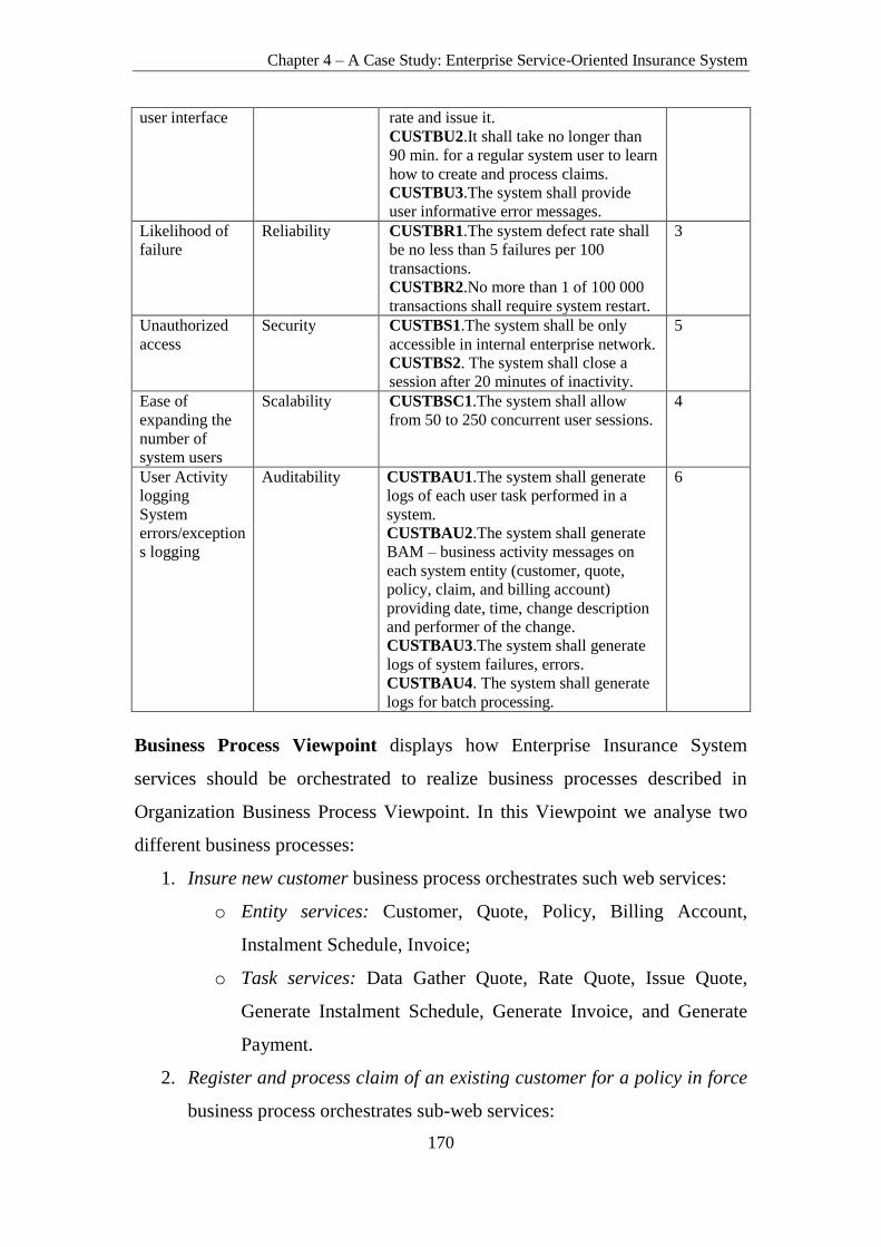
Chapter 4 – A Case Study: Enterprise Service-Oriented Insurance System
170
user interface rate and issue it.
CUSTBU2.It shall take no longer than
90 min. for a regular system user to learn
how to create and process claims.
CUSTBU3.The system shall provide
user informative error messages.
Likelihood of
failure
Reliability CUSTBR1.The system defect rate shall
be no less than 5 failures per 100
transactions.
CUSTBR2.No more than 1 of 100 000
transactions shall require system restart.
3
Unauthorized
access
Security CUSTBS1.The system shall be only
accessible in internal enterprise network.
CUSTBS2. The system shall close a
session after 20 minutes of inactivity.
5
Ease of
expanding the
number of
system users
Scalability CUSTBSC1.The system shall allow
from 50 to 250 concurrent user sessions.
4
User Activity
logging
System
errors/exception
s logging
Auditability CUSTBAU1.The system shall generate
logs of each user task performed in a
system.
CUSTBAU2.The system shall generate
BAM – business activity messages on
each system entity (customer, quote,
policy, claim, and billing account)
providing date, time, change description
and performer of the change.
CUSTBAU3.The system shall generate
logs of system failures, errors.
CUSTBAU4. The system shall generate
logs for batch processing.
6
Business Process Viewpoint displays how Enterprise Insurance System
services should be orchestrated to realize business processes described in
Organization Business Process Viewpoint. In this Viewpoint we analyse two
different business processes:
1. Insure new customer business process orchestrates such web services:
o Entity services: Customer, Quote, Policy, Billing Account,
Instalment Schedule, Invoice;
o Task services: Data Gather Quote, Rate Quote, Issue Quote,
Generate Instalment Schedule, Generate Invoice, and Generate
Payment.
2. Register and process claim of an existing customer for a policy in force
business process orchestrates sub-web services:

Chapter 4 – A Case Study: Enterprise Service-Oriented Insurance System
171
o Entity services: Customer, Quote, Policy, Billing Account,
Claim, Refund Payment,
o Task services: Search for Customer, Evaluate Claim, and Refund
Claim.
Viewpoint describes concerns regarding non-functional requirements of
Business Domain Representatives, ESOA Centre of Excellence, EA
Governance Board, ESOA Governance Board, Solution Development Team
stakeholder groups and provides NFRs with their priorities (Table 4-4).
Table 4-4. Business Process Viewpoint Non-Functional Requirements
User Concern Requirement
Category
Requirement Priority
Stakeholder Group: Business Domain Representatives
System availability
during working and
non-working hours
Availability BSNBA1.The system shall be
available 13 working hours a day
for business processes: Insure a
new Customer, Register and
process claim.
BSNBA2.The system shall be
available for automatic claim
recovery payments generation for
30 minutes during non-working
hours.
1
System capability to
perform requests in
time saving manner
Performance BSNBP1.It shall take no longer
than 12 minutes to Insure new
Customer including all manual
steps performed by a system user
and all automatic steps performed
by system.
BSNBP2. It shall take no longer
than 2 days to Register and process
the claim of an existing customer
for a policy in force: 1) claim
creation should take no longer than
7 minutes, 2) claim evaluation ~ 1
working day and claim recovery
payments processing ~1 working
day (including all manual steps
performed by a system user and all
automatic steps performed by the
system).
2
Likelihood of failure Reliability BSNBR1.The system defect rate
shall be no less than 5 failed
business processes Insure new
Customer, Register and process
claim per 100.
3
Unauthorized access Security BSNBS1.Only authorized and
authenticated system users shall be
5

Chapter 4 – A Case Study: Enterprise Service-Oriented Insurance System
172
able to perform business processes
Insure new Customer, Register and
process claim.
Ease of expanding
the number of system
users
Scalability BSNBSC1.The system shall allow
for ~ 300 brokers to Insure new
Customer concurrently.
4
System
errors/exceptions
logging
Auditability BSNBAU1.The system shall
generate logs of system failures,
during the execution of the business
processes Insure new Customer,
Register and process claim.
6
Stakeholder Group: EA Governance Board, ESOA Centre of Excellence, ESOA
Governance Board, Solution Development Team
System availability
during working and
non-working hours
Availability BSNDA1.The system shall be
available for 13 working hours a
day.
BSNDA2.The system shall be
available for 8 hours of batch
processing a day (e.g. policy issue,
claim recovery payments
generation and processing etc.)
1
System capability to
perform requests in
time saving manner
Performance BSNDP1.System shall provide a
response to each user manual action
in no more than 1.5 seconds.
2
Likelihood of failure Reliability BSNDR1.The system defect rate
shall be less than 1 failed business
process per 100.
3
Unauthorized access Security BSNDS1.Each service composed
into business processes shall have
privileges described, so that only
authorized users can execute it.
5
Ease of expanding
the number of system
users
Scalability BSNDSC1.The system shall allow
from 50 to 250 concurrent user
sessions.
4
User Activity logging
System
errors/exceptions
logging
Auditability BSNDAU1.The system shall
generate logs of system failures
during the execution of the business
processes.
12
Ease of service
change
Modifiability BSNDM1.Each service in a
business process must be easily and
cost-effectively modifiable, so that
the change in business process or
business process entity could be
easily reflected in a service or a
service composition.
BSNDM2.The modification of one
service shall not pose a change in
other service.
6
Ease of service
extension
Extensibility BSNDE1.Each service in a
business process must be extensible
without affecting other services.
BSNDE2.ESOA system shall be
extensible using one of the
following ways:
7

Chapter 4 – A Case Study: Enterprise Service-Oriented Insurance System
173
- Modifying service source
code;
- Configuring services when
only interface specification is
provided;
- Combine modification of
service source code with
configuration of services.
Availability to test
each service/business
process
independently
Testability BSNDT1.Each service in a
business process shall be tested
independently of other services.
BSNDT2.Each business process
composed of services shall be
tested independently of other
business processes.
10
Accuracy of service
discoverability
Discoverability BSNDD1.Each service composing a
business process must be easily,
accurately, and suitably found at
both design time and runtime (e.g.
the system shall discover 99 of 100
of required service interfaces
accurately).
11
Ease of service
adaptability
Adaptability BSNDAD1.Each service composing
a business process shall be feasibly
adapted at both design time and
runtime. Services composing a
business process shall be combined
in new and different ways.
Additional services shall be added,
or adapted, services shall be
swapped in where needed.
8
Ease of system
composability
Composability BSNDC1.Each service shall be
easily composed into service
composition (e.g. 99 of 100 services
should be easily composed).
9
Service Viewpoint displays Enterprise Insurance System services from which
business processes described in Organization Business Process Viewpoint are
composed. In this Viewpoint we analyse non-functional requirements for the
following list of services:
1. Entity services: Customer, Quote, Policy, Billing Account, Invoice,
Instalment Schedule, Claim, Refund Payment;
2. Task services: Rate Quote, Issue Quote, Generate Instalment Schedule,
Search for Customer, Evaluate Claim, Refund Claim.
Stakeholder groups that are interested in this viewpoint are the following:
Business Domain Representatives, EA Governance Board, ESOA Centre of

Chapter 4 – A Case Study: Enterprise Service-Oriented Insurance System
174
Excellence, ESOA Governance Board, and Service Development Team.
Viewpoint frames the following quality attributes: discoverability, adaptability,
composability, availability, performance, security, scalability, reliability,
extensibility, testability, modifiability (Table 4-5).
Table 4-5. Service Viewpoint Non-Functional Requirements
User Concern
Requirement
Category
Requirement Priority
Stakeholder Group: Business Domain Representatives
System availability
during working and
non-working hours
Availability SERBA1. The system shall be
available 13 working hours a day
for business processes: Insure new
Customer, Register and process
claim.
SERBA2.The system shall be
available for automatic claim
recovery payments generation for
30 minutes during non-working
hours.
1
System capability to
perform requests in
time saving manner
Performance SERBP1.It shall take no longer
than 12 minutes to Insure new
Customer including all manual
steps performed by system user and
all automatic steps performed by
system.
SERBP2. It shall take no longer
than 2 days to Register and process
the claim of an existing customer
for a policy in force: 1) claim
creation should take no longer than
7 minutes, 2) claim evaluation ~ 1
working day and claim recovery
payments processing ~1 working
day (including all manual steps
performed by a system user and all
automatic steps performed by the
system).
2
Likelihood of failure Reliability SERBR1.The system defect rate
shall be no less than 5 failed
business processes Insure new
Customer, Register and process
claim per 100.
3
Unauthorized access Security SERBS1.Only authorized and
authenticated system users shall be
able to perform business processes
Insure new Customer, Register and
process claim.
5
Ease of expanding
the number of system
users
Scalability SERBSC1.The system shall allow
for ~ 300 brokers to Insure new
Customer concurrently.
4
System Auditability SERBAU1.The system shall 6

Chapter 4 – A Case Study: Enterprise Service-Oriented Insurance System
175
errors/exceptions
logging
generate logs of system failures,
during the execution of the business
processes Insure new Customer,
Register and process claim.
Stakeholder Group: EA Governance Board, ESOA Centre of Excellence, ESOA
Governance Board, Service Development Team
System availability
during working and
non-working hours
Availability SERDA1. The services Customer,
Quote, Policy, Billing Account,
Invoice, Instalment Schedule,
Claim, Refund Payment, Rate
Quote, Issue Quote, Generate
Instalment Schedule, Search for
Customer, Evaluate Claim, and
Refund Claim shall be available 13
working hours a day.
SERDA2.The system shall be
available for 8 hours of batch
processing a day (e.g. policy issue,
claim recovery payments
generation and processing etc.)
1
System capability to
perform requests in
time saving manner
Performance SERDP1.System shall provide a
response to each user manual action
in no more than 1.5 seconds.
2
Likelihood of failure Reliability SERDR1.The system defect rate
shall be less than 1 failed service
per 100.
3
Unauthorized access Security SERDS1.Each service shall have
privileges described, so that only
authorized users can access and
execute it.
5
Ease of expanding
the number of system
users
Scalability SERDSC1.The system shall allow
from 50 to 250 concurrent user
sessions.
4
User Activity logging
System
errors/exceptions
logging
Auditability SERDAU1.The system shall
generate logs of system failures
during the execution of services.
12
Ease of service
change
Modifiability SERDM1.Each service must be
easily and cost-effectively
modifiable, so that the change in
business process or business
process entity could be easily
reflected in a service.
SERDM2.The modification of one
service shall not pose a change in
other service.
6
Ease of service
extension
Extensibility SERDE1.Each service in a
business process must be extensible
without affecting other services.
SERDE2.Each service shall be
extensible using one of the
following ways:
- Modifying service source code
- Configuring services when
7

Chapter 4 – A Case Study: Enterprise Service-Oriented Insurance System
176
only interface specification is
provided;
- Combine modification of
service source code with
configuration of services.
Availability to test
each service/business
process
independently
Testability SERDT1.Each service shall be
tested independently of other
services.
10
Accuracy of service
discoverability
Discoverability SERDD1.Each service must be
easily, accurately, and suitably
found at both design time and
runtime (e.g. The system shall
discover 99 of 100 of required
service interfaces accurately).
11
Ease of service
adaptability
Adaptability SERDAD1.Each service shall be
feasibly adapted at both design time
and runtime. Additional services
shall be added, or adapted, services
shall be swapped in where needed.
8
Ease of system
composability
Composability SERDC1.Each service shall be
easily composed into service
composition (e.g. 99 of 100 services
should be easily composed).
9
4.2. Identification of Requirement Conflicts, Modelling
User Concerns and NFRs Using GRL and UCM,
Developing Alternative Solutions, Elaborating
Solutions and Performing Judgment and Trade-off
in Consumer Viewpoint
4.2.1. Identification of Requirement Conflicts in Customer Viewpoint
Customer Viewpoint has two stakeholder groups – ESOA Customers and
Business Domain Representatives. User concerns, NFRs and their priorities
provided in Table 4-3 were checked for mutual consistency using tabular
method (Table 4-6). Independent requirements were marked with “0”,
overlapping – “10”, conflicting – “1”.

Chapter 4 – A Case Study: Enterprise Service-Oriented Insurance System
177
Table 4-6. Consumer Viewpoint Non-Functional Requirements’ Check for Consistency ESOA
Consumers
Business
Domain
Representative
s
CU
ST
CA
1
CU
ST
CA
2
CU
ST
CP
1
CU
ST
CP
2
CU
ST
CP
3
CU
ST
CU
1
CU
ST
CU
2
CU
ST
CU
3
CU
ST
CR
1
CU
ST
CR
2
CU
ST
CR
3
CU
ST
CS
1
CU
ST
CS
2
CU
ST
CS
3
CU
ST
CS
4
CU
ST
CS
C1
CU
ST
CA
U1
CU
ST
CA
U2
CUSTBA1 1 0 0 0 0 0 0 0 0 0 0 0 0 0 0 0 0 0
CUSTBA2 0 1 0 0 0 0 0 0 0 0 0 0 0 0 0 0 0 0
CUSTBP1 0 0 1 0 0 0 0 0 0 0 0 0 0 0 0 0 0 0
CUSTBP2 0 0 0 0 1 0 0 0 0 0 0 0 0 0 0 0 0 0
CUSTBU1 0 0 0 0 0 0 0 0 0 0 0 0 0 0 0 0 0 0
CUSTBU2 0 0 0 0 0 0 0 0 0 0 0 0 0 0 0 0 0 0
CUSTBU3 0 0 0 0 0 0 0 0 0 0 0 0 0 0 0 0 0 0
CUSTBR1 0 0 0 0 0 0 0 0 1 1 1 0 0 0 0 0 0 0
CUSTBR2 0 0 0 0 0 0 0 0 0 0 0 0 0 0 0 0 0 0
CUSTBS1 0 0 0 0 0 0 0 0 0 0 0 0 0 0 1 0 0 0
CUSTBS2 0 0 0 0 0 0 0 0 0 0 0 0 0 0 0 0 0 0
CUSTBSC1 0 0 0 0 0 0 0 0 0 0 0 0 0 0 0 10 0 0
CUSTBAU1 0 0 0 0 0 0 0 0 0 0 0 0 0 0 0 0 10 0
CUSTBAU2 0 0 0 0 0 0 0 0 0 0 0 0 0 0 0 0 0 10
CUSTBAU3 0 0 0 0 0 0 0 0 0 0 0 0 0 0 0 0 0 0
CUSTBAU4 0 0 0 0 0 0 0 0 0 0 0 0 0 0 0 0 0 0
4.2.2. Modelling of User Concerns and NFRs in Consumer Viewpoint
using GRL and UCM
ESOA Customers and Business Domain Representatives user concerns, NFRs
and their priorities were modelled using GRL (Figure 4-6) and UCM notation
(Figure 4-3, Figure 4-4, Figure 4-5). In the GRL diagram, user concerns are
modelled as “goals”, NFRs as softgoals. Independent softgoals were not
connected as they have no contribution to each other. Overlapping softgoals
were connected to each other using unknown contribution type (coloured in
blue in Figure 4-6). Conflicting softgoals were connected to each other using
some negative contribution type (coloured in yellow in Figure 4-6). In Figure
4-3, we depict business process – Insure New Customer – a UCM diagram,
which displays ESOA sub-systems that participate in business process with
responsibilities allocated to them. In Figure 4-4, we depict detailed Log-in to
Enterprise Insurance System process diagram. In Figure 4-5, we depict
business process – Register Claim for an Existing Customer – UCM diagram.

Chapter 4 – A Case Study: Enterprise Service-Oriented Insurance System
178
Figure 4-3. UCM Diagram: Business Process – Insure New Customer
Figure 4-4. UCM Diagram: Business Process – Insure New Customer Sub-Process – Log In

Chapter 4 – A Case Study: Enterprise Service-Oriented Insurance System
179
Figure 4-5. UCM Diagram: Business Process – Register Claim for an Existing Customer

Figure 4-6. GRL Diagram: Consumer Viewpoint User Concerns and Non-Functional Requirements
Chap
ter 4 –
A C
ase Stu
dy: E
nterp
rise Serv
ice-Orien
ted In
suran
ce System
180

Chapter 4 – A Case Study: Enterprise Service-Oriented Insurance System
181
4.2.3. Developing of Alternative Solutions in Consumer Viewpoint
Customer Viewpoint resulted to have conflicting (Table 4-7) and overlapping
requirements (Table 4-8). All conflicting and overlapping requirements were
analysed in respect of their priority and business value.
Table 4-7. Conflicting Non-Functional Requirements in Consumer Viewpoint
ESOA Customers Business Domain Representatives
CUSTCA1.The system shall be available
during working hours 8 AM- 11 PM. Priority
– 1.
CUSTBA1.The system shall be available 13
working hours a day. Priority - 1.
CUSTCA2.The system shall be available at
non-working hours for various automatic
processes (e.g. policy issue, claim recovery
payments generation etc.). Priority – 1.
CUSTBA2.The system shall be available 8
hours for batch processing a day (e.g. policy
issue, claim recovery payments generation
etc.). Priority – 1.
CUSTCP1.It shall take no longer than 2
seconds to save a new customer/quote/claim
in a system. Priority – 2.
CUSTBP1.The system shall provide a
response to each user manual action in no
more than 3 seconds. Priority – 2.
CUSTCP3.It shall take no longer than 3
seconds to issue the policy, create billing
account and generate instalment schedule.
Priority – 2.
CUSTBP2. The system shall be able to issue
100 quotes or renew policies in 6 minutes
time during batch processing. Priority – 2.
CUSTCR1.The system shall allow creating
99 of 100 customers successfully. Priority –
3.
CUSTBR1.The system defect rate shall be
less than 5 failures per 100 transactions.
Priority – 3.
CUSTCR2.The system shall allow creating,
rating and issuing 95 of 100 quotes
successfully. Priority – 3.
CUSTBR1.The system defect rate shall be
less than 5 failures per 100 transactions.
Priority – 3.
CUSTCR3.The system shall allow creating
95 of 100 claims and their recovery payments
successfully. Priority – 3.
CUSTBR1.The system defect rate shall be
less than 5 failures per 100 transactions.
Priority – 3.
CUSTCS4.The system shall be accessible
using VPN. Priority – 5.
CUSTBS1.The system shall be only
accessible in an internal enterprise network.
Priority – 5.
Table 4-8. Overlapping Requirements in Consumer Viewpoint
ESOA Customers Business Domain Representatives
CUSTCSC1.From 50 to 250 users shall be
able to operate with system at the same time.
Priority – 4.
CUSTBSC1.The system shall allow from 50
to 250 concurrent user sessions. Priority – 4.
CUSTCAU1.The system shall generate logs
of each user task performed in a system.
Priority – 6.
CUSTBAU1.The system shall generate logs
of each user task performed in a system.
Priority – 6.
CUSTCAU2.The system shall generate
BAM – business activity messages on each
system entity (customer, quote, policy, and
billing account) providing date, time, change
description and performer of the change.
Priority – 6.
CUSTBAU2.The system shall generate
BAM – business activity messages on each
system entity (customer, quote, policy, claim,
and billing account) providing date, time,
change description and performer of the
change. Priority – 6.

Chapter 4 – A Case Study: Enterprise Service-Oriented Insurance System
182
4.2.4. Elaborating Solutions and Performing Judgment and Trade-off
in Consumer Viewpoint
During conflicting requirement analysis it was decided to eliminate either one
of conflicting requirements or eliminate both requirements and create a new
one that better reflects business need by merging two conflicting requirements.
As a result, CUSTBA1, CUSTBA2, CUSTBP1, CUSTBP2, CUSTBS1 were
eliminated from further analysis. CUSTCR1 and CUSTBR1 requirements were
rephrased to new CUSTCR1 requirement sounding “The system shall allow
creating 95 of 100 customers successfully. Priority – 3.”
During overlapping requirement analysis it was decided to eliminate one of the
overlapping requirements and leave only one that better reflects business needs.
Respectively, CUSTBSC1, CUSTBAU1, CUSTBAU2 were eliminated from
further analysis.
4.3. Identification of Requirement Conflicts, Modelling
User Concerns and NFRs Using GRL and UCM,
Developing Alternative Solutions, Elaborating
Solutions and Performing Judgment and Trade-off
in Business Process Viewpoint
4.3.1. Identification of Requirement Conflicts in Business Process
Viewpoint
Business Process Viewpoint has the following stakeholder groups – Business
Domain Representatives, ESOA Centre of Excellence, ESOA Governance
Board, and Solution Development Team. User concerns, NFRs and their
priorities provided in Table 4-4 were checked for mutual consistency using
tabular method (Table 4-9). Independent requirements were marked with “0”,
overlapping – “10”, conflicting – “1”.

Chapter 4 – A Case Study: Enterprise Service-Oriented Insurance System
183
Table 4-9 Business Process Viewpoint Non-Functional Requirements’ Check for Consistency Business Domain
Representatives
ESOA
Centre
of Excellence,
ESOA Governance
Board,
Solution
Development Team
BS
NB
A1
BS
NB
A2
BS
NB
P1
BS
NB
P2
BS
NB
R1
BS
NB
S1
BS
NB
SC
1
BS
NB
AU
1
BSNDA1 10 0 0 0 0 0 0 0
BSNDA2 0 1 0 0 0 0 0 0
BSNDP1 0 0 0 0 0 0 0 0
BSNDR1 0 0 0 0 1 0 0 0
BSNDS1 0 0 0 0 0 10 0 0
BSNDSC1 0 0 0 0 0 0 1 0
BSNDAU1 0 0 0 0 0 0 0 10
BSNDM1 0 0 0 0 0 0 0 0
BSNDM2 0 0 0 0 0 0 0 0
BSNDE1 0 0 0 0 0 0 0 0
BSNDE2 0 0 0 0 0 0 0 0
BSNDT1 0 0 0 0 0 0 0 0
BSNDT2 0 0 0 0 0 0 0 0
BSNDD1 0 0 0 0 0 0 0 0
BSNDAD1 0 0 0 0 0 0 0 0
BSNDC1 0 0 0 0 0 0 0 0
4.3.2. Modelling of User Concerns and NRFs in Business Process
Viewpoint using GRL and UCM
Business Domain Representatives, ESOA Centre of Excellence, ESOA
Governance Board, Solution Development Team user concerns, NFRs and their
priorities were modelled using GRL notation (Figure 4-7). Independent
softgoals were not connected as they have no contribution to each other.
Overlapping softgoals were connected to each other using unknown
contribution type (for more details see section 1.4.1 Goal-Oriented
Requirement Language) (coloured in blue in Figure 4-7). Conflicting softgoals
were connected to each other using some negative contribution type (coloured
in yellow in Figure 4-7).

Figure 4-7. Business Process Viewpoint User Concerns and Non-Functional Requirements Modelling Using GRL
Chap
ter 4 –
A C
ase Stu
dy: E
nterp
rise Serv
ice-Orien
ted In
suran
ce System
184

Chapter 4 – A Case Study: Enterprise Service-Oriented Insurance System
185
4.3.3. Developing of Alternative Solutions in Business Process
Viewpoint
Business Process Viewpoint resulted in having conflicting (Table 4-10) and
overlapping requirements (Table 4-11). All conflicting and overlapping
requirements were analysed with respect to their priority and business value.
Table 4-10. Conflicting Non-Functional Requirements in Business Process Viewpoint
Business Domain Representatives
ESOA Centre of Excellence, ESOA
Governance Board, Solution Development
Team
BSNBA2.The system shall be available for
automatic claim recovery payments
generation for 30 minutes during non-
working hours. Priority- 1.
BSNDA2.The system shall be available for 8
hours of batch processing a day (e.g. policy
issue, claim recovery payments generation
and processing etc.) Priority – 1.
BSNBR1.The system defect rate shall be no
less than 5 failed business processes Insure
new Customer, Register and process claim
per 100. Priority – 3.
BSNDR1.The system defect rate shall be less
than 1 failed business process per 100.
BSNBSC1.The system shall allow for ~ 300
brokers to Insure new Customer concurrently.
Priority – 4.
BSNDSC1.The system shall allow from 50
to 250 concurrent user sessions. Priority – 4.
Table 4-11. Overlapping Non-Functional Requirements in Business Process Viewpoint
Business Domain Representatives ESOA Centre of Excellence, ESOA
Governance Board, Solution Development
Team
BSNBA1.The system shall be available 13
working hours a day for business processes:
Insure new Customer, Register and process
claim. Priority – 1.
BSNDA1.The system shall be available for
13 working hours a day. Priority – 1.
BSNBAU1.The system shall generate logs of
system failures, during the execution of the
business processes Insure new Customer,
Register and process claim. Priority – 6.
BSNDAU1.The system shall generate logs of
system failures during the execution of the
business processes. Priority – 12.
BSNBS1.Only authorized and authenticated
system users shall be able to perform
business processes Insure new Customer,
Register and process claim.
BSNDS1.Each service composed into
business processes shall have privileges
described, so that only authorized users can
execute it.
4.3.4. Elaborating Solutions and Performing Judgement and Trade-off
in Business Process Viewpoint
During conflicting requirement analysis it was decided to eliminate both
requirements and create a new one that better reflects business needs by
merging the previous two. As a result, BSNBA2 and BSNDA2 requirements

Chapter 4 – A Case Study: Enterprise Service-Oriented Insurance System
186
were rephrased to new BSNBA2 requirement sounding “The system shall be
available for 8 hours of batch processing a day (e.g. policy issue, claim
recovery payments generation and processing etc.)”. BSNBR1 and BSNDR1
requirements were rephrased to new BSNDR1 requirement sounding “The
system defect rate shall be less than 1 failed business process per 100”.
BSNBSC1 and BSNDSC1 requirements were rephrased to new BSNDSC1
requirement sounding “The system shall allow from 50 to 250 concurrent user
sessions”.
During overlapping requirement analysis it was decided to eliminate one of
overlapping requirements and leave only one that better reflects business needs.
Respectively, BSNDA1, BSNDAU1, BSNDS1 were eliminated from further
analysis.
4.4. Identification of Requirement Conflicts, Modelling
User Concerns and NFRs Using GRL and UCM,
Developing Alternative Solutions, Elaborating
Solutions and Performing Judgment and Trade-off
in Customer and Business Process Viewpoints
4.4.1. Identification of Requirement Conflicts between Customer and
Business Process Viewpoints
Analysed and adjusted Customer and Business Process Viewpoint requirements
were further checked for mutual consistency using tabular method (Table
4-12). Independent requirements were marked with “0”, overlapping – “10”,
conflicting – “1”.

Chapter 4 – A Case Study: Enterprise Service-Oriented Insurance System
187
Table 4-12. Customer and Business Process Viewpoints Non-Functional Requirements’
Check for Consistency Consum
er
Viewpoi
nt /
Business
Process
Viewpoi
nt
CU
ST
CA
1
CU
ST
CA
2
CU
ST
CP
1
CU
ST
CP
2
CU
ST
CP
3
CU
ST
CU
1
CU
ST
CU
2
CU
ST
CU
3
CU
ST
CR
1
CU
ST
CR
2
CU
ST
CR
3
CU
ST
CS
1
CU
ST
CS
2
CU
ST
CS
3
CU
ST
CS
4
CU
ST
BU
1
CU
ST
BU
2
CU
ST
BU
3
CU
ST
BR
2
CU
ST
BS
2
CU
ST
BS
C1
CU
ST
BA
U1
CU
ST
BA
U2
CU
ST
BA
U3
CU
ST
BA
U4
BSNBA1 1 0 0 0 0 0 0 0 0 0 0 0 0 0 0 0 0 0 0 0 0 0 0 0 0
BSNBA2 0 1 0 0 0 0 0 0 0 0 0 0 0 0 0 0 0 0 0 0 0 0 0 0 0
BSNBP1 0 0 0 0 0 1 1 0 0 0 0 0 0 0 0 0 0 0 0 0 0 0 0 0 0
BSNBP2 0 0 0 0 0 0 0 1 0 0 0 0 0 0 0 0 0 0 0 0 0 0 0 0 0
BSNBR1 0 0 0 0 0 0 0 0 1 1 1 0 0 0 0 0 0 0 0 0 0 0 0 0 0
BSNBS1 0 0 0 0 0 0 0 0 0 0 0 1
0
0 1
0
0 0 0 0 0 0 0 0 0 0 0
BSNBSC
1
0 0 0 0 0 0 0 0 0 0 0 0 0 0 0 0 0 0 0 0 1
0
0 0 0 0
BSNBA
U1
0 0 0 0 0 0 0 0 0 0 0 0 0 0 0 0 0 0 0 0 0 1
0
0 1
0
1
0
BSNDP1 0 0 1 1 1 0 0 0 0 0 0 0 0 0 0 0 0 0 0 0 0 0 0 0 0
BSNDM
1
0 0 0 0 0 0 0 0 0 0 0 0 0 0 0 0 0 0 0 0 0 0 0 0 0
BSNDM
2
0 0 0 0 0 0 0 0 0 0 0 0 0 0 0 0 0 0 0 0 0 0 0 0 0
BSNDE1 0 0 0 0 0 0 0 0 0 0 0 0 0 0 0 0 0 0 0 0 0 0 0 0 0
BSNDE2 0 0 0 0 0 0 0 0 0 0 0 0 0 0 0 0 0 0 0 0 0 0 0 0 0
BSNDT1 0 0 0 0 0 0 0 0 0 0 0 0 0 0 0 0 0 0 0 0 0 0 0 0 0
BSNDT2 0 0 0 0 0 0 0 0 0 0 0 0 0 0 0 0 0 0 0 0 0 0 0 0 0
BSNDD1 0 0 0 0 0 0 0 0 0 0 0 0 0 0 0 0 0 0 0 0 0 0 0 0 0
BSNDA
D1
0 0 0 0 0 0 0 0 0 0 0 0 0 0 0 0 0 0 0 0 0 0 0 0 0
BSNDC1 0 0 0 0 0 0 0 0 0 0 0 0 0 0 0 0 0 0 0 0 0 0 0 0 0
4.4.2. Modelling of User Concerns and NFRs in Customer and
Business Process Viewpoints using GRL and UCM
Customer and Business Process Viewpoints user concerns, NFRs and their
priorities were modelled using GRL notation (Table 4-8). Independent
softgoals were not connected as they have no contribution to each other.
Overlapping softgoals were connected to each other using unknown
contribution type (coloured in blue in Figure 4-8; for more details see section
1.4.1 Goal-Oriented Requirement Language). Conflicting softgoals were
connected to each other using some negative contribution type (coloured in
yellow in Figure 4-8).

Figure 4-8. Customer and Business Process Viewpoint User Concerns and Non-Functional Requirements Modelling Using GRL
Chap
ter 4 –
A C
ase Stu
dy: E
nterp
rise Serv
ice-Orien
ted In
suran
ce System
188

Chapter 4 – A Case Study: Enterprise Service-Oriented Insurance System
189
4.4.3. Developing of Alternative Solutions in Customer and Business
Process Viewpoint
Customer and Business Process Viewpoints resulted in having conflicting (see
Table 4-13) and overlapping requirements (Table 4-14). All conflicting and
overlapping requirements were analysed with respect to their priority and
business value.
Table 4-13. Conflicting Non-Functional Requirements in Consumer and Business Process
Viewpoints
Customer Viewpoint Business Process Viewpoint
CUSTCA1.The system shall be available
during working hours 8 AM- 11 PM.
BSNBA1.The system shall be available 13
working hours a day for business processes:
Insure new Customer, Register and process
claim.
CUSTCA2.The system shall be available at
non-working hours for various automatic
processes (e.g. policy issue, claim recovery
payments generation etc.).
BSNBA2.The system shall be available for
automatic claim recovery payments
generation for 30 minutes during non-
working hours.
CUSTCP1.It shall take no longer than 2
seconds to save new customer/quote/claim in
a system.
BSNDP1.The system shall provide a
response to each user manual action in no
more than 1.5 seconds.
CUSTCP2.It shall take no longer than 2
seconds to rate a quote and calculate
premiums.
BSNDP1.The system shall provide a
response to each user manual action in no
more than 1.5 seconds.
CUSTCP3. It shall take no longer than 3
seconds to issue the policy, create billing
account and generate instalment schedule.
BSNDP1.The system shall provide a
response to each user manual action in no
more than 1.5 seconds.
CUSTCU1.95% of users shall be able to
create a customer in a system in less than 4
minutes.
BSNBP1.It shall take no longer than 12
minutes to Insure new Customer including
all manual steps performed by system user
and all automatic steps performed by system.
CUSTCU2.95% of users shall be able to
create a quote in a system and issue it in less
than 10 minutes.
BSNBP1.It shall take no longer than 12
minutes to Insure new Customer including
all manual steps performed by system user
and all automatic steps performed by system.
CUSTCU3.95% of users shall be able to
create a claim in a system in less than 6
minutes.
BSNBP2.It shall take no longer than 2 days
to Register and process claim of an existing
customer for a policy in force: 1) claim
creation should take no longer than 7
minutes, 2) claim evaluation ~ 1 working day
and claim recovery payments processing ~1
working day (including all manual steps
performed by system user and all automatic
steps performed by system).
CUSTCR1.The system shall allow creating
95 of 100 customers successfully.
BSNBR1.The system defect rate shall be less
than 1 failed business process per 100.

Chapter 4 – A Case Study: Enterprise Service-Oriented Insurance System
190
CUSTCR2.The system shall allow creating,
rate and issuing 95 of 100 quotes
successfully.
BSNBR1.The system defect rate shall be less
than 1 failed business process per 100.
CUSTCR3.The system shall allow creating
95 of 100 claims and their recovery payments
successfully.
BSNBR1.The system defect rate shall be less
than 1 failed business process per 100.
Table 4-14 Overlapping Non-Functional Requirements in Consumer and Business Process
Viewpoint
Customer Viewpoint Business Process Viewpoint
CUSTCS1.The system shall be accessible to
100% of its authorized users.
BSNBS1.Only authorized and authenticated
system users shall be able to perform
business processes Insure new Customer,
Register and process claim.
CUSTCS3. The system shall not be
accessible to unauthenticated, unauthorized
users.
BSNBS1.Only authorized and authenticated
system users shall be able to perform
business processes Insure new Customer,
Register and process claim.
CUSTBSC1.From 50 to 250 users shall be
able to operate with system at the same time.
BSNBSC1. The system shall allow from 50
to 250 concurrent user sessions. Priority – 4.
CUSTBAU1.The system shall generate logs
of each user task performed in a system.
Priority – 6.
BSNBAU1.The system shall generate logs of
system failures, during the execution of the
business processes Insure new Customer,
Register and process claim.
CUSTBAU3.The system shall generate logs
of system failures, errors
BSNBAU1.The system shall generate logs of
system failures, during the execution of the
business processes Insure new Customer,
Register and process claim.
CUSTBAU4. The system shall generate logs
for batch processing.
BSNBAU1.The system shall generate logs of
system failures, during the execution of the
business processes Insure new Customer,
Register and process claim.
4.4.4. Elaborating Solutions and Performing Judgment and Trade-off
in Customer and Business Process Viewpoints
During conflicting requirement analysis it was decided to eliminate one of
conflicting requirements and leave only one of them that better reflects
business need. As a result, BSNBA1, BSNBA2, BSNDP1, BSNBP1, BSNBP2,
BSNBR1 were eliminated from further analysis.
During overlapping requirement analysis it was decided to eliminate one of the
overlapping requirements and leave only one that better reflects business needs.

Chapter 4 – A Case Study: Enterprise Service-Oriented Insurance System
191
Respectively, BSNBS1, BSNBSC1, and BSNBAU1 were eliminated from
further analysis.
4.5. Summary
In the previous chapter (Chapter: 3.4 Spiral Process Model for Capture and
Analysis of Non-Functional Requirements of Service-Oriented Enterprise
Systems) we defined a spiral process model for ESOA non-functional
requirements capture and analysis that includes such steps:
1. Define ESOA Stakeholders, ESOA non-functional requirements and
ESOA viewpoints framing them;
2. Identify non-functional requirements conflicts and overlaps;
3. Model non-functional requirements conflicts and overlaps using GRL
and UCM notations;
4. Develop alternative solutions/alternative non-functional requirements;
5. Elaborate proposed solutions/non-functional requirements;
6. Perform proposed non-functional requirements judgment and trade-off.
The set of our proposed ESOA viewpoints were as follows: Enterprise Strategy
Viewpoint, Enterprise Business Processes Viewpoint, Consumer Viewpoint,
Business Process Viewpoint, and Service Viewpoint.
For a case study to illustrate our process model we have chosen an Enterprise
Service-Oriented Insurance System which provides personal insurance
services.
For testing the first step of our process model we described ESOA viewpoints
in the following way:
1. Enterprise Strategy Viewpoint was described by formulating mission
and vision statements and also by using SWOT and PEST analysis. The
analysis reflected that Enterprise Insurance System is required in order
to reach company's vision, to use the technological advancement in the
world defined by PEST analysis, to overcome company’s weaknesses
and threats and to exploit opportunities defined by SWOT analysis.

Chapter 4 – A Case Study: Enterprise Service-Oriented Insurance System
192
2. Organization Business Processes Viewpoint was defined with the two
most common business processes: 1) insure new customer, 2) register
claim for an existing customer. These processes were modelled using
Business Process Modelling Notation – BPMN.
3. Consumer, Business Process and Service Viewpoints were described by
defining stakeholder groups, their concerns regarding non-functional
requirements, non-functional requirements categories and non-
functional requirements with their priorities.
For testing the second step in of process model, non-functional
requirements were checked for mutual consistency using tabular method.
Initially, during the first iteration, we checked non-functional requirements
within the limits of one viewpoint by comparing non-functional
requirements from different stakeholder groups. Secondly, during the
second iteration, we compared non-functional requirements from Customer
Viewpoint to Business Process Viewpoint requirements. Furthermore, we
decided not to search for non-functional requirements conflicts and overlaps
in Service Viewpoint, as two viewpoints were enough to test our process
model and the third would only have increased the amount of work and
repeated the results. As a result, Service Viewpoint was abandoned from
further steps in case study.
For testing the third step of our process model we modelled Consumer and
Business Process Viewpoints using GRL and UCM notations. Consumer
Viewpoint included Use Case Map (UCM) diagrams for both business
processes defined in Organization Business Process Viewpoint and a Goal
Requirement Language (GRL) diagram that depicted two stakeholder
groups concerns regarding non-functional requirements and non-functional
requirements themselves. GRL diagram visualized non-functional
requirements conflicts and overlaps. The UCM diagram displayed ESOA
sub-systems with their responsibilities. GRL and UCM diagrams are usually
used together because GRL defines the system users’ goals and UCM
allocates those goals to the system sub-systems (or components). Business

Chapter 4 – A Case Study: Enterprise Service-Oriented Insurance System
193
Process Viewpoint was modelled using only the GRL diagram as UCM
diagrams from Customer Viewpoint were reused here. The GRL diagram
depicted stakeholder groups concerns regarding non-functional
requirements and non-functional requirements themselves. GRL diagram
visualized non-functional requirements conflicts and overlaps.
During the testing the fourth step in our process model we developed
alternative solutions and proposals how non-functional requirements conflicts
and overlaps could be solved in Customer and Business Process Viewpoints.
During testing the fifth and sixth steps in our process model we elaborated our
solutions and performed judgment and trade-off in Customer and Business
Process Viewpoints. We have chosen two-fold elaboration approach – either to
eliminate one of conflicting and overlapping requirements, or to eliminate both
conflicting and overlapping requirements and to construct a new one.
To sum up, performed case study showed that, on one hand, our proposed
spiral process model for ESOA non-functional requirements capturing and
analysis can be used when gathering non-functional requirements for ESOA
solutions but, on the other hand, it contains some drawbacks and limitations. A
more detailed discussion is provided in the next chapter.

Chapter 5 – Discussion of Issues and Limitations
194
Chapter 5
Discussion of Issues and Limitations
The aim of the thesis research was to propose a spiral process model for
capturing and analysis non-functional requirements for enterprise service-
oriented systems that would help to solve service specification issues and
challenges that are encountered in service-oriented requirement engineering –
SORE. We propose a spiral process model constructs viewpoints for non-
functional requirements analysis starting from the highest level of abstraction –
enterprise strategy – and refining them step by step to concrete and detailed
service level requirements. The process model defines possible stakeholder
groups, non-functional requirements types, describes a method how to find
conflicting non-functional requirements and proposes a requirements
negotiation process model for conflict resolution. The Requirement negotiation
process recommends using User Requirements Notation (URN) standard
languages: Goal-oriented Requirement Language (GRL) and Use Case Maps
(UCM) notation to model viewpoints that contain conflicting and overlapping
non-functional requirements. These languages are designed to model system
requirements by showing how they affect high level business goals and
business strategy.
Although the results of the thesis are comprehensive and applicable to a real
world software design, some limitations can be noted:
Process model can be very hard to apply in practice if no direct mapping
between business goals (when they are unknown or unclear) and system
functions exists, as the main aim of this model is to help to choose such
system functions with such quality characteristics that help to achieve
business goals the best.

Chapter 5 – Discussion of Issues and Limitations
195
The appliance of process model requires a huge amount of manual work
when defining ESOA non-functional requirements and allocating them
to different viewpoints, looking for conflicting requirements using
tabular method, creating GRL and UCM diagrams, negotiating
requirement conflicts and overlaps iteratively.
5.1. Open Problems
The following open problems have to be investigated as well in order to
increase process model’s applicability:
A solution for process model automation has to be thought of and
designed. It would decrease the amount of manual work and decrease
the possibility of human mistake.
No research has been done to find out whether the process model can
also be used for modelling traditional systems non-functional
requirements. It is assumed that light adjustments – ESOA Viewpoints
(including stakeholders and non-functional requirements) need to be
redesigned to remove service-orientation principles.
In addition to this, no research has been performed to find out whether
the process model can also be used for capturing and analysing
functional requirements. It is assumed, that at least non-functional
requirements (treated as concerns in viewpoints) have to be changed
with functional requirements and these should be treated as concerns in
viewpoints.

196
Results and Conclusions
The results of the thesis research can be summarized as follows:
1. Service-oriented requirement engineering (SORE) lacks coherent,
comprehensive and mature requirement engineering process models.
There exist issues and challenges in SORE that have not been solved
yet.
2. ESOA systems are of high complexity, usually have many different
stakeholder groups with different expectations of systems non-functional
characteristics and conflicting expectations inevitably rise. In addition to
this, ESOA systems non-functional requirements differ from traditional
systems non-functional requirements and there are no mature service-
oriented requirement engineering process models targeted at them.
3. Several service-oriented system development methodologies such as
IBM RUP/SOMA, SOAF, SOUP, the methodology by Tomas Erl, and
methodology by Michael Papazoglou have been proposed to ensure
successful service-oriented systems development by providing process
guidance and proven best practices from already accomplished SOA
projects. Although these methodologies help to structure service-
oriented systems development processes, they are not aimed at defining
SORE process and do not provide any approach to requirement
capturing and analysis.
4. A set of typical stakeholder groups for ESOA systems has been
proposed with the main differences between stakeholders for traditional
systems and ESOA systems highlighted.
5. A set of quality attributes (non-functional requirements) for ESOA
systems has been proposed by drawing the main attention to their
differences with respect to traditional systems non-functional
requirements.

197
6. Process model for capturing and analysis non-functional requirements of
service-oriented enterprise systems has been proposed; it is designed
incorporating traditional and service-oriented requirement gathering
process models, conflicts management approaches and techniques, EA
standards and frameworks.
7. Process model recommends using i*-based modelling languages (GRL
and UCM) and viewpoints that are widely used in Enterprise
Architecture (EA) standards and frameworks and have not been
previously thoroughly researched for their applicability to solve issues
and challenges of service specification for service-oriented enterprise
systems.
8. Process model includes five viewpoints – Enterprise Strategy viewpoint,
Enterprise Business Processes viewpoint, Consumer viewpoint,
Business Process viewpoint, and Service viewpoint. A case study
performed on an insurance domain revealed that non-functional
requirements analysis using viewpoints can help to find conflicting
requirements and resolve requirements conflicts, because service-
oriented enterprise systems are complex ones and usually stakeholders
have conflicting and overlapping requirements.
9. Process model is designed to benefit from the iterative requirement
negotiation process and allows renegotiation. Requirement negotiation
process is based on a spiral model to accommodate the dynamic
requirements engineering. Each round of the cycle resolves more
conflicted requirements and achieves better resolution. The model
considers the win conditions of all stakeholders that participate in ESOA
project as it identifies and evaluates alternative approaches for satisfying
the win conditions. It also helps to identify and resolve risks that stem
from the selected approach by performing elaboration, judgment and the
trade-off of selected solution.
10. Process model is based on the main aim of service-orientation – to
develop systems that support enterprise business strategy, objectives and

198
goals and, as a result, is primarily concerned with exposing “why” (by
modelling business goals) certain non-functional requirements are more
important than the others.
11. Process model can be used in conjunction with service-oriented systems
development methodologies to improve requirement capturing, analysis
capabilities and, at the same time, increase system quality and usability.

199
References
Ahmad, S. (2008). Negotiation in the Requirements Elicitation and Analysis
Process. In Proceedings of the 19th Australian Conference on Software
Engineering. IEEE Computer Society Press, p. 683-689.
Amyot, D., Mussbacher, G. (2011). User Requirements Notation: The First Ten
Years, The Next Ten Years. Journal of Software, Vol. 6, No. 5 (2011), p.
747-768.
Arsanjani, A. (1999). Service Provider: A Meta-Domain Pattern and its
Business Framework Implementation, In Online Proceedings of the Pattern
Languages in Programming Conference. [Accessed 2015-06-24]
http://hillside.net/plop/plop99/proceedings/Arsanjani/provider3.pdf
Arsanjani, A. (2001). Enterprise Component: A compound pattern for building
component architectures. In Proceedings of TOOLS 2001, IEEE Computer
Society Press.
Arthur, J.D., Gröner, M.K. (2005). An operational model for structuring the
requirements generation process. The Requirements Engineering Journal,
Vol. 10, No. 1 (January 2005), p. 45-62.
Bano, M., Irkram, N. (2010). Issues and challenges of Requirement
Engineering in Service Oriented Software Development, IEEE Computer
Society Press, p. 64-69.
Barker, D. (2004). itSMF – ITIL Best Practice. Are we Getting the Message?
ServiceTalk – Journal of IT Service Management Forum, 66, 3.
Bianco, P., Kotermanski, R., Merson, P. (2007). Evaluating a Service-Oriented
Architecture, Carnegy Mellon: Carnegie Mellon University.
Bichler, M., Lin, K-J. (2006). Service-Oriented Computing. Computer 39(3), p.
99-101.
Bieberstein, N., Bose, S., Fiammante, M., Jones, K., Shah, R. (2006). Service-
oriented Architecture Compass – Business Value, Planning, and Enterprise
Roadmap. Upper Saddle River: Pearson as IBM Press.

200
Boehm, B. (1988). A Spiral Model of Software Development and
Enhancement. Computer, Vol. 21, No. 5, (May 1988), p. 61-72.
Boehm, B. (2000). Spiral Development: Experience, Principles, and
Refinements, Special Report CMU/SEI-2000-SR-008. [Accessed 2015-06-
24] http://www.sei.cmu.edu/reports/00sr008.pdf
Chinnici, R., Moreau, J. J., Ryman, A., Weerawarana, S. (2007). Web Services
Description Language (WSDL) Version 2.0 Part 1: Core Language, W3C
Recommendation.
Choi, S. W., Her, J. S., Kim, S. D. (2007). Modeling QoS Attributes and
Metrics for Evaluating Services in SOA Considering Consumers'
Perspective as the First Class Requirement. APSCC, IEEE, p. 398-405 .
Chung L., Nixon, J. M. B., Yu, A. (2000). Non-functional Requirements in
Software Engineering. Springer, Reading, Massachusetts. ISBN 978-1-
4615-5269-7.
Clements, P., Kazman, R., Klein, M. (2002). Evaluating Software
Architectures. Boston, MA: Addison-Wesley.
Clements, P. (2005). 1471 (IEEE Recommended Practice for Architectural
Description of Software-Intensive Systems), CMU/SEI-2005-TN-017,
Software Architecture Technology Initiative, Carnegie-Mellon Software
Engineering Institute.
Crnkovic, G. D. (2010). Constructive Research and Info-Computational
Knowledge Generation. Model-based reasoning in science and technology,
Studies in Computational Intelligence, Vol. 314/2010, p. 359-380.
DoDAF. Department of Defense Architecture Framework Version 2.02, 2010.
[Accessed 2015-06-24] http://dodcio.defense.gov/dodaf20.aspx
Erl, T. (2005). Service-Oriented Architecture: Concepts, Technology and
Design. Prentice Hall PTR. ISBN 0132715821, 9780132715829.
Erl, T. (2008). SOA Principles of Service Design. Prentice Hall PTR. ISBN
0132344823, 9780132344821.

201
Erradi, A., Anand, S., Kulkarni, N. (2006). SOAF: An Architectural
Framework for Service Definition and Realization. IEEE International
Conference on Services Computing (SCC'06), p. 151-158.
Errikson, I., McFadden, F. (1993). Quality Function Deployment: A Tool to
Improve Software Quality. Information and Software Technology 35, 9.
E2AF. Extended Enterprise Architecture Framework Essentials Guide v1.5.
2006. Institute For Enterprise Architecture Developments. [Accessed 2015-
06-24] http://www.enterprise-
architecture.info/Images/E2AF/Extended%20Enterprise%20Architecture%2
0Framework%20Essentials%20Guide%20v1.5.pdf
Fernandez-Martinez, L. F., Lemus-Olalde, C. (2004). Improving the IEEE std
1471-2000 for Communication among Stakeholders and Early Design
Decisions, Proceeding (418) Software Engineering.
Flores, F., Mora, M., Álvarez, F., O’Connor, R., Macias, J. (2008). Handbook
of Research on Modern Systems Analysis and Design Technologies and
Applications. In IGI Global (eds), p. 96 -111.
Flores, F., Mora, M., Álvarez, F., Garza L., Durán, H. (2009). From
Requirements Engineering to Service-oriented Requirements Engineering:
An Analysis of Transition. Phoenix, AZ, USA, December 14, 2009, s.n., p.
1-13.
Flores, F., Mora, M., Álvarez, F., Garza L., Durán, H. (2010). Towards a
Systematic Service-oriented Requirements Engineering Process (S-SoRE).
ENTERprise Information Systems Communications in Computer and
Information Science, Vol. 109, p. 111-120.
Flyvbjerg, B. (2004). Five misunderstandings about case-study research. In C.
Seale, G. Gobo, D. Silverman (eds.). Qualitative Research Practices. London
and Thousand Oaks, CA: Sage, p. 420-434.
Gall, N., Perkins, E. (2003). The Intersection of Web Services and Security
Management: A Service-Oriented Security Architecture. [Accessed 2015-
06-24]

202
http://people.cs.vt.edu/~kafura/cs6204/Readings/WebServices/MetaGroupW
hitePaperWebServices.pdf
Galster, M., Bucherer, E. (2008). Towards Requirements Engineering in a
Service-Oriented Environment - Extending the SOA Interaction Triangle.
Computational Intelligence for Modelling Control & Automation,
International Conference on, p. 1099-1104, IEEE.
Grady, R., Caswell, D. (1987). Software Metrics: Establishing a Company-
Wide Program. Englewood Cliffs: Prentice-Hall.
Hart, C. (1998). Doing a literature review: Releasing the social science research
imagination. London, SAGE Publications.
Hofmeister, C., Nord, R., Soni, D. (1999). Applied Software Architecture.
Addison-Wesley, Boston.
IBM RUP/SOMA. IBM Rational Unified Process for Service-Oriented
Modelling and Architecture. [Accessed 2015-06-24] http://www.michael-
richardson.com/processes/rup_classic/#soa.rup_soma/customcategories/rup_
soma_roadmaps_1618FD4A.html
IEEE Std 1471:2000. Recommended Practice for Architectural Description of
Software-intensive. [Accessed 2015-06-24] Systems.
https://standards.ieee.org/findstds/standard/1471-2000.html
IEEE P1723, Standard for a Service-Oriented Architecture (SOA) Reference
Architecture. [Accessed 2015-06-24]
http://standards.ieee.org/develop/project/1723.html
ISO/IEC 10746-1:1998. Information technology — Open Distributed
Processing — Reference model: Overview. [Accessed 2015-06-24]
http://www.iso.org/iso/catalogue_detail.htm?csnumber=20696
ISO/IEC 10746-2:1996. Information technology — Open Distributed
Processing — Reference model: Foundations. [Accessed 2015-06-24]
http://www.iso.org/iso/catalogue_detail.htm?csnumber=18836
ISO/IEC 10746-3:1996. Information technology — Open Distributed
Processing — Reference model: Architecture

203
ISO/IEC 10746-4:1998. Information technology — Open Distributed
Processing — Reference Model: Architectural semantics. [Accessed 2015-
06-24] http://www.iso.org/iso/catalogue_detail.htm?csnumber=20698
ISO/IEC/IEEE 42010:2011. Systems and software engineering - Architecture
description. [Accessed 2015-06-24]
https://standards.ieee.org/findstds/standard/42010-2011.html
ISO/IEC 25010:2011. Systems and software engineering — Systems and
software Quality Requirements and Evaluation (SQuaRE) — System and
software quality models. [Accessed 2015-06-24]
http://www.iso.org/iso/catalogue_detail.htm?csnumber=35733
ISO/IEC 9126:2000. Information Technology - Software Product Quality -
Part 1: Quality Model.
ITU-T (2008). ITU-T Recommendation Z.151 User Requirements Notation
(URN), International Telecommunication Union. [Accessed 2015-06-24]
https://www.itu.int/rec/T-REC-Z.151/en
Yu, E. (2009). Social Modeling and i*. In Conceptual Modeling: Foundations
and Applications, Lecture Notes in Computer Science, Vol. 5600, p. 99-121
Kan, S. (2002). Metrics and Models in Software Quality Engineering, 2nd
Edition. Addison-Wesley Professional.
Koch, C., 2005. Enterprise Architecture: A New Blueprint For The Enterprise,
CIO Magazine.
Kotonya, G., Sommervile, I. (1998). Requirements Engineering Process And
Techniques. John Wiley & Sons.
Kroll, P., Kruchten, P., Booch, G. (2003). The Rational Unified Process Made
Easy: A Practitioner's Guide to the RUP: A Practitioner's Guide to the
RUP. Addison-Wesley, ISBN-13: 978-0321166098, ISBN-10: 0321166094
Kruchten, P. (1995). Architectural Blueprints — The “4+1” View Model of
Software Architecture. IEEE Software 12 (6), p. 42-50.
Lamsweerde, A. (2000). Requirements Engineering in the Year 00: A Research
Perspective. In Proceedings of the ICSE 2000 Conference, p. 5-19.

204
Layzell, P. et al (2000). Service-based Software: The Future for Flexible
Software, In Proceedings of Asia-Pacific Software Engineering
Conference, IEEE Computer Society.
Laurence, S., Margolis, E. (2003). Concepts and conceptual analysis.
Philosophy and Phenomenological Research 67, p. 253-282.
Leite, P., Freeman, P. (1991). Requirements Validation Through Viewpoint
Resolution. IEEE Transactions on Software Engineering 17, 12, p. 1253-
1269.
Linington, P. F., Milosevic. Z., Tanaka, A., Vallecillo, A. (2011). Building
Enterprise Systems with ODP. An Introduction to Open Distributed
Processing. Chapman & Hall/CRC Press, ISBN: 978-1-4398-6625-2.
Luckham, D.C., Kenney, J.J., Augustin, L.M., Vera, J., Bryan, D., Mann, W.
(1995). Specification and analysis of system architecture using RAPIDE,
IEEE Transactions on Software Engineering, 21(4), p. 336–355.
Lukka, K. (2003). The constructive research approach. In: L. Ojala, O-P.
Hilmola (eds.) Case study research in logistics. Publications of the Turku
School of Economics and Business Administration, Series B 1:2003, p. 83-
101.
Machado, A., Silva, F. J. (2007). Toward a richer view of the scientific method.
The role of conceptual analysis. American Psychologist, 62(7), p. 671–681.
McGovern, J., Tyagi, S., Stevens, M., Matthew, S., (2003). Java Web Services
Architecture. San Francisco, CA: Morgan Kaufmann Publishers.
Mingers, J., (2001). Combining IS Research Methods: Towards a Pluralist
Methodology. Information Systems Research, Vol. 12, No. 3, p. 240–259.
Minoli, D., (2008). Enterprise Architecture A to Z: Frameworks, Business
Process Modeling, SOA, and Infrastructure Technology. Auerbach
Publications. Print ISBN: 978-0-8493-8517-9.
Newcomer, E., Lomow, G. (2004). Understanding SOA with Web services
(Independent Technology Guides). Addison-Wesley.
Newcomer, E. & Lomow, G., 2005. Understanding SOA with Web services.
s.l.:Addison-Wesley.

205
Nuseibeh, B., Easterbrook, S. (2000). Requirements engineering: a roadmap.
Proceedings of the Conference on the Future of Software Engineering
(ICSE '00), p. 35-46.
O'Brien, Liam., Bass, Len., Merson, P. F. (2005). Quality Attributes and
Service-Oriented Architectures. Software Engineering Institute. Paper 449.
OMG formal. (2008). Systems Modeling Language, version 1.1.
Papazoglou, M.P., 2006. Service-Oriented Design and Development
Methodology. Int. J. of Web Engineering and Technology (IJWET), Vol. 2,
No 4, p. 412-442.
Penrod, J., Hupcey, J. (2005). Enhancing methodological clarity: principle-
based concept analysis. Journal of Advanced Nursing Vol. 50, No. 4, p.
403–409.
Ramollari, E., Dranidis, D., Simons, A.JH. (2007). A survey of service oriented
development methodologies. The 2nd European Young Researchers
Workshop on Service Oriented Computing, p.75-80.
Rational Software. (1998). Rational Unified Process: Best Practices for
Software Development Teams. Rational Software White Paper TP026B,
Rev 11/01. [Accessed 2015-06-24]
http://www.ibm.com/developerworks/rational/library/content/03July/1000/
1251/1251_bestpractices_TP026B.pdf
RM-ODP. Reference Model of Open Distributed Processing. [Accessed 2015-
06-24] http://www.rm-odp.net/
Runeson, P., Höst, M. (2009). Guidelines for conducting and reporting case
study research in software engineering. Empirical Software Engineering,
Vol. 14, No. 2, 14:131–164.
Russo, A., Nusbeibeh, B., Kramer, J. (1999). Restructuring Requirements
Specifications. Software, IEE Proceedings, Vol. 146, No. 1 ), p. 44 - 53.
Sambeth, M. (2006). Enterprise SOA. Mastering Future Business. Presentation
slides, SAP AG
SAP. (2008). Enterprise SOA Development Handbook 1.1, [Accessed 2015-06-
24]

206
http://www.sdn.sap.com/irj/scn/go/portal/prtroot/docs/library/uuid/40db473
5-02f9-2a10-b198-a888a056bb67?overridelayout=true
Schekkerman, J. (2001–2006). Another View at Extended Enterprise
Architecture Viewpoits. Institute For Enterprise Architecture
Developments (IFEAD). [Accessed 2015-06-24] http://www.enterprise-
architecture.info/EA_Services-Oriented-Enterprise.htm
Schekkerman, J. (2004). Another View at Extended Enterprise Architecture
Viewpoits. Institute For Enterprise Architecture Developments (IFEAD).
[Accessed 2015-06-24] http://www.enterprise-
architecture.info/Images/Extended%20Enterprise/E2A-
Viewpoints_IFEAD.PDF
Schekkerman, J. (2005). Trends in Enterprise Architecture 2005 in Reports of
the Third Measurement. Institute For Enterprise Architecture
Developments (IFEAD).
Shams-Ul-Arif, Khan, Q., Gahyyur, S. A. K. (2009-2010). Requirement
Engineering Processes Tools/Technologies & Methodologies, International
Journal of Reviews in Computing, p. 41-56.
Shaw, M. (1990). Prospects for an Engineering Discipline of Software. IEEE
Software, 7(6): 15-24.
SOA GRM, SOA Governance Technical Standard: SOA Governance
Reference Model. [Accessed 2015-06-24]
http://www.opengroup.org/soa/source-book/gov/sgrm.htm
SOA-RM. (2006). Reference Model for Service-Oriented Architecture 1.0. s.l.:
OASIS. [Accessed 2015-06-24] https://www.oasis-
open.org/committees/tc_home.php?wg_abbrev=soa-rm
SOA-RAF. (2012). Reference Architecture Fundation for Service-Oriented
Architecture Version 01, s.l.: OASIS. [Accessed 2015-06-24]
http://docs.oasis-open.org/soa-rm/soa-ra/v1.0/cs01/soa-ra-v1.0-cs01.pdf
SOA Source Book, 2009. Van Haren Publishing.
207
Soni, D., Nord, R., Hofmeister, C., 1995. Software architecture in industrial
applications. In: Proceedings of the 17th International Conference on
Software Engineering (ICSE-17). ACM Press, p. 196–207.
Sommerville, I., Sawyer, P. (1997). Viewpoints: principles, problems and a
practical approach to requirements engineering. Annals of Software
Engineering, Vol. 3, p. 101–130.
SOUP. Service-Oriented Unified Process. [Accessed 2015-06-24]
http://www.kunalmittal.com/html/soup.html
Svanidzaitė, S (2012). A comparison of SOA methodologies Analysis &
Design Phases. Baltic DB & IS 2012, Tenth International Baltic
Conference on Databases and Information Systems, p. 202-207.
Svanidzaitė, S. (2014a). Towards Service-oriented Requirement Engineering.
In Proceedings of IVUS 2014, XIX Interuniversity Conference Information
Society and University Studies, p. 15-20.
Svanidzaitė, S. (2014b). An Approach to SOA Methodology: SOUP
Comparison with RUP and XP, Computational Science and Techniques
2,1, p. 238-252.
Svanidzaitė, S. (2014c). A Methodology for Capturing and Managing Non-
Functional Requirements for Enterprise Service-Oriented Systems. Baltic
J. Modern Computing Vol. 2, No.3, p. 117-131.
TAFIM (1990). Technical Architecture Framework for Information
Management. [Accessed 2015-06-24] http://en.wikipedia.org/wiki/TAFIM
The Open Group SOA Reference Architecture (SOA-RA), (2011). Technical
Standard. [Accessed 2015-06-24] http://www.opengroup.org/soa/source-
book/soa_refarch/index.htm
Trienekens, J., Bouman, J.J., van der Zwan, M. (2004). Specification of Service
Level Agreements: Problems, Principles and Practices, Software Quality
Journal, 12(1), p. 43-57.
Tsai, W., Jin, Z., Wang, P., Wu, B. (2007). Requirement Engineering in
Service-Oriented System Engineering, IEEE International Conference on e-
Business Engineering, p. 661 – 668.

208
TOGAF 9.1 (2011). An Open Group standard. [Accessed 2015-06-24]
http://pubs.opengroup.org/architecture/togaf9-doc/arch/
UML 2.0. (2007). Unified Modeling Language: Superstructure, Ver. 2.1.1,
OMG Adopted Specification, OMG document formal/2007-02-05, Object
Management Group, Needham, MA.
Van Eck, P., Wieringa, R. (2003). Requirements Engineering for Service-
Oriented Computing: a Position Paper, Proceedings of the First
International E-Services Workshop, ICEC 03, Pittsburgh, USA, p. 23-28
WEB (a). The Open Group SOA Reference Architecture (SOA-RAF).
[Accessed 2015-06-24] http://www.opengroup.org/soa/source-
book/soa_refarch/index.htm
WEB (aa). SSL, Secure Sockets Layers Protocol. [Accessed 2015-06-24]
https://www.cisco.com/web/about/ac123/ac147/archived_issues/ipj_1-
1/ssl.html
WEB (ab). Kerberos, The Network Authentication Protocol. [Accessed 2015-
06-24] http://web.mit.edu/kerberos/
WEB (ac). SAML, Security Assertions Markup Language. [Accessed 2015-06-
24] https://www.oasis-open.org/standards#samlv2.0
WEB (ad). XACML, eXtensible Access Control Markup Language. [Accessed
2015-06-24] https://www.oasis-open.org/standards#xacmlv3.0
WEB (ae). BTP, Business Transactions Protocol. [Accessed 2015-06-24]
https://www.oasis-
open.org/committees/tc_home.php?wg_abbrev=business-transaction
WEB (af). WS-Tx, Web Services Transactions. [Accessed 2015-06-24]
https://www.oasis-open.org/committees/tc_home.php?wg_abbrev=ws-tx
WEB (ag). Ministry of Defence Architecture Framework (MODAF). [Accessed
2015-06-24] https://www.gov.uk/mod-architecture-framework
WEB (ah). Open Distributed Processing (ODP). [Accessed 2015-06-24]
http://dictionary.reference.com/browse/open+distributed+processing
WEB (ai). Service Level Agreement (SLA). [Accessed 2015-06-24]
http://searchitchannel.techtarget.com/definition/service-level-agreement

209
WEB (aj). The Unified Profile for DoDAF/MODAF (UPDM). [Accessed 2015-
06-24] http://www.omg.org/spec/UPDM
WEB (ak). ESB, Enterprise Service Bus. [Accessed 2015-06-24]
http://www.oracle.com/technetwork/articles/soa/ind-soa-esb-1967705.html
WEB (al). Vision statement. [Accessed 2015-06-24]
http://www.businessdictionary.com/definition/vision-statement.html
WEB (b). Zachman Institute for Framework Advancement (ZIFA). [Accessed
2015-06-24] http://www.zifa.com/
WEB (c). TOGAF®, an Open Group standard. [Accessed 2015-06-24]
http://www.opengroup.org/subjectareas/enterprise/togaf
WEB (d). Business Process Modelling Notation. [Accessed 2015-06-24]
http://www.bpmn.org/
WEB (e). Mission Statement. [Accessed 2015-06-24]
http://www.businessdictionary.com/definition/mission-statement.html
WEB (f). PEST analysis. [Accessed 2015-06-24]
http://www.businessballs.com/pestanalysisfreetemplate.htm
WEB (g). Software Development Life Cycle. [Accessed 2015-06-24]
http://searchsoftwarequality.techtarget.com/definition/systems-
development-life-cycle
WEB (h). SWOT analysis. [Accessed 2015-06-24]
http://www.businessballs.com/swotanalysisfreetemplate.htm
WEB (i). Frequently Asked Questions: ISO/IEC/IEEE 42010. [Accessed 2015-
06-24] http://www.iso-architecture.org/ieee-1471/faq.html
WEB (j). Wright ADL website. [Accessed 2015-06-4]
http://www.cs.cmu.edu/~able/wright/
WEB (k). The Open Group, ArchiMate 1.0 Specification. [Accessed 2015-06-
24] http://www.archimate.org/
WEB (l). TOGAF 8.1.1. Developing Architecture Views. [Accessed 2015-06-
24] http://pubs.opengroup.org/architecture/togaf8-doc/arch/chap31.html
WEB (m). CORBA, Common Object Request Broker Architecture. [Accessed
2015-06-24] http://www.corba.org/

210
WEB (n). RMI, Remote Method Invocation, [Accessed 2015-06-24]
http://www.oracle.com/technetwork/java/javase/tech/index-jsp-
136424.html
WEB (o). DCOM, Distributed Component Object Model. [Accessed 2015-06-
24] http://whatis.techtarget.com/definition/DCOM-Distributed-
Component-Object-Model
WEB (p). RPC, Remote Procedure Call. [Accessed 2015-06-24]
https://technet.microsoft.com/en-
us/library/cc787851%28v=ws.10%29.aspx
WEB (r). Microsoft .NET. [Accessed 2015-06-24]
http://www.microsoft.com/net
WEB (s). JAVA EE, Oracle Java Enterprise Edition. [Accessed 2015-06-24]
http://www.oracle.com/technetwork/java/javaee/overview/index.html
WEB (t). WSDL, Web Services Definition Language. [Accessed 2015-06-24]
http://www.w3.org/standards/techs/wsdl#w3c_all
WEB (u). SOAP, Simple Object Access Protocol. [Accessed 2015-06-24]
http://www.w3.org/standards/techs/soap#w3c_all
WEB (v). WS-BPEL, Web Services Business Process Execution Language
Version 2.0. [Accessed 2015-06-24] http://docs.oasis-
open.org/wsbpel/2.0/wsbpel-v2.0.pdf
WEB (w). WS-Security, Web Services Security. [Accessed 2015-06-24]
https://www.oasis-open.org/committees/tc_home.php?wg_abbrev=wss
WEB (x). ebXML, Electronic Business using eXtensible Markup Language.
[Accessed 2015-06-24] http://www.ebxml.org/
WEB (y). Web Services Interoperability Organization. [Accessed 2015-06-24]
http://www.ws-i.org/
WEB (z). WS-I, Web Services Interoperability. [Accessed 2015-06-24]
http://www.oasis-ws-i.org/
Weerawarana, S., Leymann, F., Curbera, F., Ferguson, D., Storey, T. (2005).
Web Services Platform Architecture: SOAP, WSDL, WS-Policy, WS-

211
Addressing, WS-BPEL, WS-Reliable Messaging, and More. Prentice Hall
PTR. ISBN 10: 0131488740 ISBN 13: 9780131488748.
Zachman International Enterprise Architecture v3.0 (2011). [Accessed 2015-
06-24] https://www.zachman.com/about-the-zachman-framework

212
List of Publications
1. Svanidzaitė, S. (2014). Towards Service-oriented Requirement
Engineering. Proceedings of IVUS 2014, XIX Interuniversity
Conference Information Society and University Studies 2014, p. 15-20.
[Accessed 2015-06-24]
http://oras.if.ktu.lt/ivus2014/IVUS2014_preprint_2014_04_22.pdf
2. Svanidzaitė, S. (2014) A Methodology for Capturing and Managing
Non-Functional Requirements for Enterprise Service-Oriented Systems.
Baltic J. Modern Computing. Vol. 2, No.3, p. 117-131. [Accessed 2015-
06-24]
http://www.bjmc.lu.lv/fileadmin/user_upload/lu_portal/projekti/bjmc/Co
ntents/2_3_1_Svanidzaite.pdf
3. Svanidzaitė, S (2014). An Approach to SOA Development
Methodology: SOUP Comparison with RUP and XP. Computational
Science and Techniques Vol. 2, No.1 (2014), p. 238-252, ISSN: 2029-
9966. [Accessed 2015-06-24]
http://journals.ku.lt/index.php/CST/article/view/77
4. Svanidzaitė, S (2012). A comparison of SOA methodologies Analysis &
Design Phases. Baltic DB & IS 2012, Tenth International Baltic
Conference on Databases and Information Systems, July 8-11, 2012,
Vilnius, Lithuania. [Accessed 2015-06-24] http://ceur-ws.org/Vol-
924/paper19.pdf
Top Related