


Languages
Pages
Legal

SAILOR 6300 MF/HF DSC
User manual
150W/150W FCC/250W/500W

SAILOR 6300 MF/HF DSC150W/150W FCC/250W/500W
User manual
Document number: 98-131070-THR-F
Release date: August 10, 2016
i
Disclaimer
Any responsibility or liability for loss or damage in connection with the use of this product and the accompanying documentation is disclaimed by Thrane & Thrane A/S. The information in this manual is provided for information purposes only, is subject to change without notice and may contain errors or inaccuracies. Manuals issued by Thrane & Thrane A/S are periodically revised and updated. Anyone relying on this information should acquire the most current version e.g. from www.cobham.com/satcom, Service and support, or from the distributor. Thrane & Thrane A/S is not responsible for the content or accuracy of any translations or reproductions, in whole or in part, of this manual from any other source. In the event of any discrepancies, the English version shall be the governing text.
Thrane & Thrane A/S is trading as Cobham SATCOM.
Copyright
© 2016 Thrane & Thrane A/S. All rights reserved. Printed in Denmark.
Trademark Acknowledgements• Thrane & Thrane is a registered trademark of Thrane & Thrane A/S in the
European Union and the Unites States of America.
• Other product and company names mentioned in this manual may be trademarks or trade names of their respective owners.
GPL notification
The software included in this product contains copyrighted software that is licensed under the GPL/LGPL. The verbatim licenses can be found online at:
http://www.gnu.org/licenses/old-licenses/gpl-2.0.htmlhttp://www.gnu.org/licenses/old-licenses/lgpl-2.1.html
You may obtain the complete corresponding source code from us for a period of three years after our last shipment of this product, which will be no earlier than December 31, 2015, by sending a money order or check for DKK 50 to:
SW Technology/GPL Compliance,Cobham SATCOM (Thrane & Thrane A/S),Lundtoftegaardsvej 93D2800 LyngbyDENMARK
ii
Write "source for product SAILOR 6300 MF/HF DSC" in the memo line of your payment. This offer is valid to anyone in receipt of this information.
http://www.cobham.com/about-cobham/communications-and-connectivity/about-us/satcom/free-and-open-source-software-(foss).aspx
You may also find a copy of the source at http://www.thrane.com/foss.
This offer is valid to anyone in receipt of this information.
Warranties
Any attempt to install or execute software not supplied by Thrane & Thrane on this device will result in the warranty being void. Any attempt to modify the software on this device in a way not specified by Thrane & Thrane will result in the warranty being void.
iii
iv
Safety summaryThe following general safety precautions must be observed during all phases of operation, service and repair of this equipment. Failure to comply with these precautions or with specific warnings elsewhere in this manual violates safety standards of design, manufacture and intended use of the equipment. Thrane & Thrane assumes no liability for the customer's failure to comply with these requirements.
GROUND THE EQUIPMENTTo minimise shock hazard, the equipment chassis and cabinet must be connected to an electrical ground and the cable instructions must be followed.
DO NOT OPERATE IN AN EXPLOSIVE ATMOSPHEREDo not operate the equipment in the presence of flammable gases or fumes. Operation of any electrical equipment in such an environment constitutes a definite safety hazard.
KEEP AWAY FROM LIVE CIRCUITSOperating personnel must not remove equipment covers. Component replacement and internal adjustment must be made by qualified maintenance personnel. Do not service the unit with the power cable connected. Always disconnect and discharge circuits before touching them.
Service
General service must be done by skilled service personnel.
Caution! Electric shock hazard. Do not open the equipment. Only skilled service personnel may service and repair the equipment.
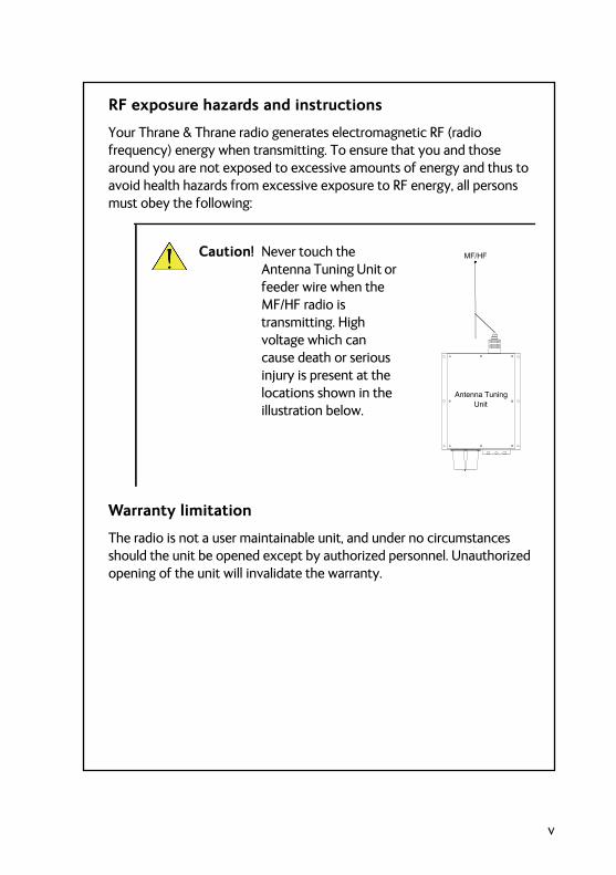
RF exposure hazards and instructions
Your Thrane & Thrane radio generates electromagnetic RF (radio frequency) energy when transmitting. To ensure that you and those around you are not exposed to excessive amounts of energy and thus to avoid health hazards from excessive exposure to RF energy, all persons must obey the following:
Warranty limitation
The radio is not a user maintainable unit, and under no circumstances should the unit be opened except by authorized personnel. Unauthorized opening of the unit will invalidate the warranty.
Caution! Never touch the Antenna Tuning Unit or feeder wire when the MF/HF radio is transmitting. High voltage which can cause death or serious injury is present at the locations shown in the illustration below. Unit
Antenna Tuning
MF/HF
SAILOR 638x
v
vi
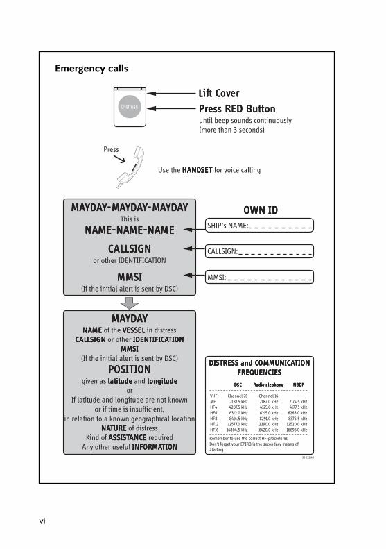
Emergency calls
MMMMMAAAAAYYYYYDDDDDAAAAAYYYYYNANANANANAMEMEMEMEME of the VVVVVEEEEESSSSSSSSSSELELELELEL in distress
CCCCCALALALALALLLLLLSSSSSIGNIGNIGNIGNIGN or other IDENIDENIDENIDENIDENTTTTTIFICIFICIFICIFICIFICAAAAATTTTTIONIONIONIONIONMMMMMMMMMMSSSSSIIIII
(If the initial alert is sent by DSC)
PPPPPOOOOOSSSSSITITITITITIONIONIONIONIONgiven as lllllatatatatatitititititudeudeudeudeude and longitlongitlongitlongitlongitudeudeudeudeude
orIf latitude and longitude are not known
or if time is insufficient,in relation to a known geographical location
NANANANANATURETURETURETURETURE of distressKind of AAAAASSSSSSSSSSIIIIISSSSSTTTTTANCANCANCANCANCEEEEE required
Any other useful INFINFINFINFINFORORORORORMMMMMAAAAATTTTTIONIONIONIONION
MMMMMAAAAAYYYYYDDDDDAAAAAYYYYY-M-M-M-M-MAAAAAYYYYYDDDDDAAAAAYYYYY-M-M-M-M-MAAAAAYYYYYDDDDDAAAAAYYYYYThis is
NANANANANAME-NAME-NAME-NAME-NAME-NAME-NAME-NAME-NAME-NAME-NAMEMEMEMEME
CCCCCALALALALALLLLLLSSSSSIGNIGNIGNIGNIGNor other IDENTIFICATION
MMMMMMMMMMSSSSSIIIII(If the initial alert is sent by DSC)
Use the HANDHANDHANDHANDHANDSSSSSETETETETET for voice calling
LLLLLififififift Ct Ct Ct Ct Covovovovovererererer
PPPPPrrrrreeeeessssss RED Buttons RED Buttons RED Buttons RED Buttons RED Buttonuntil beep sounds continuously(more than 3 seconds)
SHIP‘s NAME:
CALLSIGN:
MMSI:
OWN OWN OWN OWN OWN IDIDIDIDID
99-132140
Press
VHFMFHF4HF6HF8HF12HF16
Channel 702187.5 kHz4207.5 kHz6312.0 kHz8414.5 kHz
12577.0 kHz16804.5 kHz
Channel 162182.0 kHz4125.0 kHz6215.0 kHz8291.0 kHz
12290.0 kHz16420.0 kHz
- - - - -2174.5 kHz4177.5 kHz
6268.0 kHz8376.5 kHz
12520.0 kHz16695.0 kHz
DDDDDSCSCSCSCSC RRRRRadiadiadiadiadiotototototelephonelephonelephonelephonelephonyyyyy NBDPNBDPNBDPNBDPNBDP
DIDIDIDIDISSSSSTRETRETRETRETRESSSSSSSSSS and C and C and C and C and COMOMOMOMOMMMMMMUNICUNICUNICUNICUNICAAAAATTTTTIONIONIONIONIONFREQUENCIEFREQUENCIEFREQUENCIEFREQUENCIEFREQUENCIESSSSS
_ _ _ _ _ _ _ _ _ _ _ _ _ _ _ _ _ _ _ _ _ _ _ _ _ _ _ _ _ _ _ _ _ _ _ _Remember to use the correct HF-proceduresDon‘t forget your EPIRB is the secondary means ofalerting
_ _ _ _ _ _ _ _ _ _ _ _ _ _ _ _ _ _ _ _ _ _ _ _ _ _ _ _ _ _ _ _ _ _ _ _
Preface
Radio for occupational use
TT-6300 MF/HF DSC fulfils the requirements of SOLAS and is intended for use in maritime environment.
SAILOR 6300 MF/HF DSC is designed for occupational use only and must be operated by licensed personnel only.
SAILOR 6300 MF/HF DSC is not intended for use in an uncontrolled environment by general public.
Manual overview
This manual has the following chapters:
• Introduction contains a description of the MF/HF radio and its components.
• Operation explains how to start up the radio, make and receive voice, Distress and DSC calls, including how to handle multiple sessions, Watch and Replay.
• Service & maintenance contains support information including a weekly check, diagnostics and a troubleshooting guide.
vii
Training information(for FCC approved equipment)
The TT- 6300B MF/HF DSC is designed for occupational use only and is also classified as such. It must be operated by licensed personnel only. It must only be used in the course of employment by individuals aware of both the hazards as well as the way to minimize those hazards.
The radio is thus NOT intended for use in an uncontrolled environment by general public. The SAILOR 6300 MF/HF DSC has been tested and complies with the FCC RF exposure limits for Occupational Use Only. The radio also complies with the following guidelines and standards regarding RF energy and electromagnetic energy levels including the recommended levels for human exposure:
• FCC OET Bulletin 65 Supplement C, evaluating compliance with FCC guidelines for human exposure to radio frequency electromagnetic fields.
• American National Standards Institute (C95.1) IEEE standard for safety levels with respect to human exposure to radio frequency electromagnetic fields, 3 kHz to 300 GHz
• American National Standards Institute (C95.3) IEEE recommended practice for the measurement of potentially hazardous electromagnetic fields - RF and microwaves.
Below the RF exposure hazards and instructions in safe operation of the radio within the FCC RF exposure limits established for it are described.
Warning
The SAILOR radio set generates electromagnetic RF (radio frequency) energy when transmitting. To ensure that no personnel will be exposed to excessive amounts of RF-energy and to avoid health hazards from excessive exposure to RF energy, the following safety distances must be followed:
viii
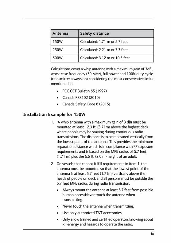
Calculations cover a whip antenna with a maximum gain of 3dBi, worst case frequency (30 MHz), full power and 100% duty cycle (transmitter always on) considering the most conservative limits mentioned in:
• FCC OET Bulletin 65 (1997)
• Canada RSS102 (2010)
• Canada Safety Code 6 (2015)
Installation Example for 150W
1. A whip antenna with a maximum gain of 3 dBi must be mounted at least 12.3 ft. (3.71m) above the highest deck where people may be staying during continuous radio transmissions. The distance is to be measured vertically from the lowest point of the antenna. This provides the minimum separation distance which is in compliance with RF exposure requirements and is based on the MPE radius of 5.7 feet (1.71 m) plus the 6.6 ft. (2.0 m) height of an adult.
2. On vessels that cannot fulfill requirements in item 1, the antenna must be mounted so that the lowest point of the antenna is at least 5.7 feet (1.71m) vertically above the heads of people on deck and all persons must be outside the 5.7 feet MPE radius during radio transmission.
• Always mount the antenna at least 5.7 feet from possible human accessNever touch the antenna when transmitting.
• Never touch the antenna when transmitting.
• Use only authorized T&T accessories.
• Only allow trained and certified operators knowing about RF-energy and hazards to operate the radio.
Antenna Safety distance
150W Calculated: 1.71 m or 5.7 feet
250W Calculated: 2.21 m or 7.3 feet
500W Calculated: 3.12 m or 10.3 feet
ix
3. If the antenna has to be placed in public areas or near people with no awareness of the radio transmission, the antenna must be placed at an even greater distance. Consult the appropriate standard for exact limits, depending on national specifications.
Failure to observe any of these warnings may cause RF exposure exceeding above mentioned limits or create dangerous conditions.
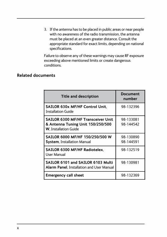
Related documents
Title and description Document number
SAILOR 630x MF/HF Control Unit, Installation Guide
98-132396
SAILOR 6300 MF/HF Transceiver Unit & Antenna Tuning Unit 150/250/500 W, Installation Guide
98-133081 98-144542
SAILOR 6000 MF/HF 150/250/500 W System, Installation Manual
98-130890 98-144591
SAILOR 6300 MF/HF Radiotelex, User Manual
98-132519
SAILOR 6101 and SAILOR 6103 Multi Alarm Panel, Installation and User Manual
98-130981
Emergency call sheet 98-132369
x
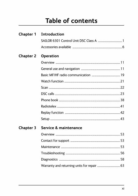
Table of contents
Chapter 1 Introduction
SAILOR 6301 Control Unit DSC Class A ....................................1
Accessories available ..........................................................................6
Chapter 2 Operation
Overview ................................................................................................11
General use and navigation ..........................................................11
Basic MF/HF radio communication ..........................................19
Watch function ...................................................................................21
Scan ..........................................................................................................22
DSC calls .................................................................................................23
Phone book ...........................................................................................38
Radiotelex ..............................................................................................41
Replay function ..................................................................................42
Setup ........................................................................................................43
Chapter 3 Service & maintenance
Overview ................................................................................................53
Contact for support ..........................................................................53
Maintenance ........................................................................................53
Troubleshooting .................................................................................56
Diagnostics ...........................................................................................58
Warranty and returning units for repair ..................................63
xi

Table of contents
Glossary ..................................................................................................................... 65
Index ..................................................................................................................... 67
xii
Chapter 111111
Intr
oduc
tion
Introduction 1
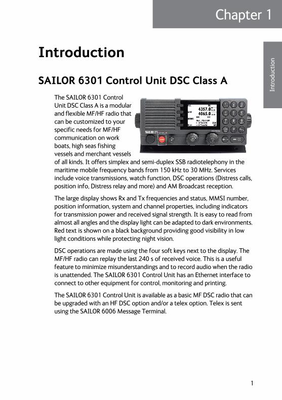
SAILOR 6301 Control Unit DSC Class AThe SAILOR 6301 Control Unit DSC Class A is a modular and flexible MF/HF radio that can be customized to your specific needs for MF/HF communication on work boats, high seas fishing vessels and merchant vessels of all kinds. It offers simplex and semi-duplex SSB radiotelephony in the maritime mobile frequency bands from 150 kHz to 30 MHz. Services include voice transmissions, watch function, DSC operations (Distress calls, position info, Distress relay and more) and AM Broadcast reception.
The large display shows Rx and Tx frequencies and status, MMSI number, position information, system and channel properties, including indicators for transmission power and received signal strength. It is easy to read from almost all angles and the display light can be adapted to dark environments. Red text is shown on a black background providing good visibility in low light conditions while protecting night vision.
DSC operations are made using the four soft keys next to the display. The MF/HF radio can replay the last 240 s of received voice. This is a useful feature to minimize misunderstandings and to record audio when the radio is unattended. The SAILOR 6301 Control Unit has an Ethernet interface to connect to other equipment for control, monitoring and printing.
The SAILOR 6301 Control Unit is available as a basic MF DSC radio that can be upgraded with an HF DSC option and/or a telex option. Telex is sent using the SAILOR 6006 Message Terminal.
1
Chapter 1: Introduction
Features
Rugged and reliable design.
Full power range on all ITU channels: 1.6 — 30 MHz for 150 W, 250 W and 500 W systems (Reduced power in the frequency range 1.6 — 4.0 MHz for 500 W according to legislation).
Powerful transceiver (150, 250 or 500 W).
Outdoor automatic antenna tuning unit.
Radiotelex using the SAILOR 6006 Message Terminal
Optionally 6 DSC Distress frequency watch keeping receiver.
Intelligent scanning for Voice, DSC and radiotelex (optional).
Ethernet with ThraneLINK.
Compliant with GMDSS in sea areas A2, A3 and A4 (Wheelmark).
Fulfills DSC specification ITU493-14.
2 SAILOR 6301 Control Unit DSC Class A
Chapter 1: Introduction11111
Intr
oduc
tion
System overview
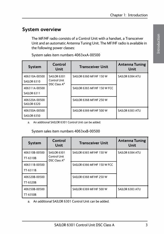
The MF/HF radio consists of a Control Unit with a handset, a Transceiver Unit and an automatic Antenna Tuning Unit. The MF/HF radio is available in the following power classes:
System sales item numbers 4063xxA-00500
System sales item numbers 4063xxB-00500
System Control Unit Transceiver Unit Antenna Tuning
Unit
406310A-00500
SAILOR 6310
SAILOR 6301 Control Unit DSC Class Aa
SAILOR 6360 MF/HF 150 W SAILOR 6384 ATU
406311A-00500
SAILOR 6311
SAILOR 6365 MF/HF 150 W FCC
406320A-00500 SAILOR 6320
SAILOR 6368 MF/HF 250 W
406350A-00500
SAILOR 6350
SAILOR 6369 MF/HF 500 W SAILOR 6383 ATU
a. An additional SAILOR 6301 Control Unit can be added.
System Control Unit Transceiver Unit Antenna Tuning
Unit
406310B-00500
TT-6310B
SAILOR 6301 Control Unit DSC Class Aa
SAILOR 6365 MF/HF 150 W SAILOR 6384 ATU
406311B-00500
TT-6311B
SAILOR 6366 MF/HF 150 W FCC
406320B-00500
TT-6320B
SAILOR 6368 MF/HF 250 W
406350B-00500
TT-6350B
SAILOR 6369 MF/HF 500 W SAILOR 6383 ATU
a. An additional SAILOR 6301 Control Unit can be added.
SAILOR 6301 Control Unit DSC Class A 3
Chapter 1: Introduction
Controls on the front
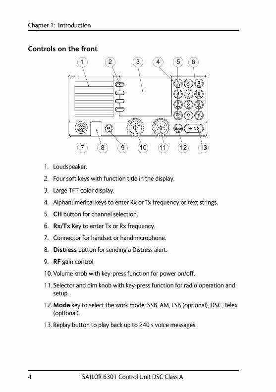
1. Loudspeaker.
2. Four soft keys with function title in the display.
3. Large TFT color display.
4. Alphanumerical keys to enter Rx or Tx frequency or text strings.
5. CH button for channel selection.
6. Rx/Tx Key to enter Tx or Rx frequency.
7. Connector for handset or handmicrophone.
8. Distress button for sending a Distress alert.
9. RF gain control.
10. Volume knob with key-press function for power on/off.
11. Selector and dim knob with key-press function for radio operation and setup.
12. Mode key to select the work mode: SSB, AM, LSB (optional), DSC, Telex (optional).
13. Replay button to play back up to 240 s voice messages.
4 SAILOR 6301 Control Unit DSC Class A
Chapter 1: Introduction11111
Intr
oduc
tion
Display overview
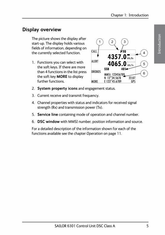
The picture shows the display after start-up. The display holds various fields of information, depending on the currently selected function.
1. Functions you can select with the soft keys. If there are more than 4 functions in the list press the soft key MORE to display further functions.
2. System property icons and engagement status.
3. Current receive and transmit frequency.
4. Channel properties with status and indicators for received signal strength (Rx) and transmission power (Tx).
5. Service line containing mode of operation and channel number.
6. DSC window with MMSI number, position information and source.
For a detailed description of the information shown for each of the functions available see the chapter Operation on page 11.
1 2 3
4
5
6
CALL
ALERT
DROBOS
MORE
MMSI: 123456789N 12°34.5678E 123°45.6789 GPS
4357.04065.0
SSB 401
SQ
kHz/Tx
kHz/Rx
22:07
SAILOR 6301 Control Unit DSC Class A 5
Chapter 1: Introduction
Accessories available
Accessory Description
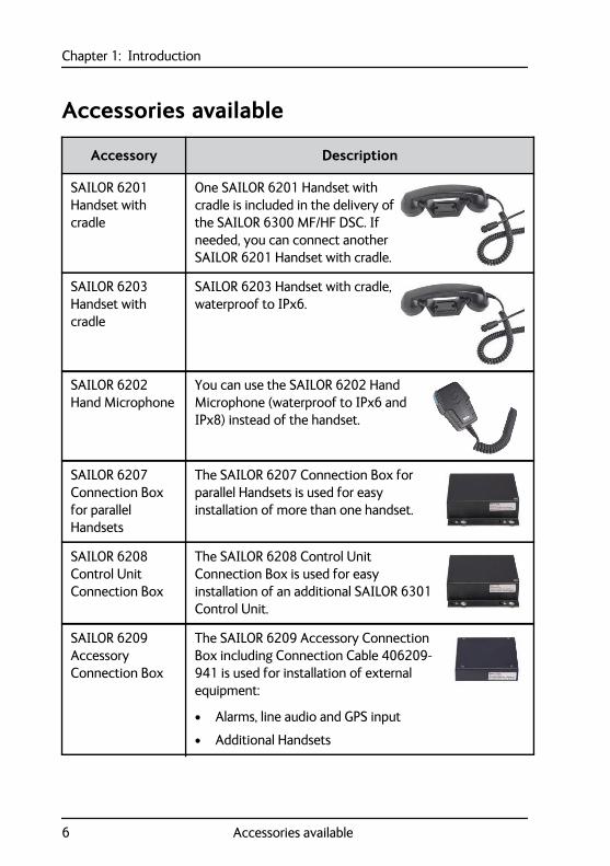
SAILOR 6201 Handset with cradle
One SAILOR 6201 Handset with cradle is included in the delivery of the SAILOR 6300 MF/HF DSC. If needed, you can connect another SAILOR 6201 Handset with cradle.
SAILOR 6203 Handset with cradle
SAILOR 6203 Handset with cradle, waterproof to IPx6.
SAILOR 6202 Hand Microphone
You can use the SAILOR 6202 Hand Microphone (waterproof to IPx6 and IPx8) instead of the handset.
SAILOR 6207 Connection Box for parallel Handsets
The SAILOR 6207 Connection Box for parallel Handsets is used for easy installation of more than one handset.
SAILOR 6208 Control Unit Connection Box
The SAILOR 6208 Control Unit Connection Box is used for easy installation of an additional SAILOR 6301 Control Unit.
SAILOR 6209 Accessory Connection Box
The SAILOR 6209 Accessory Connection Box including Connection Cable 406209-941 is used for installation of external equipment:
• Alarms, line audio and GPS input
• Additional Handsets
6 Accessories available
Chapter 1: Introduction11111
Intr
oduc
tion
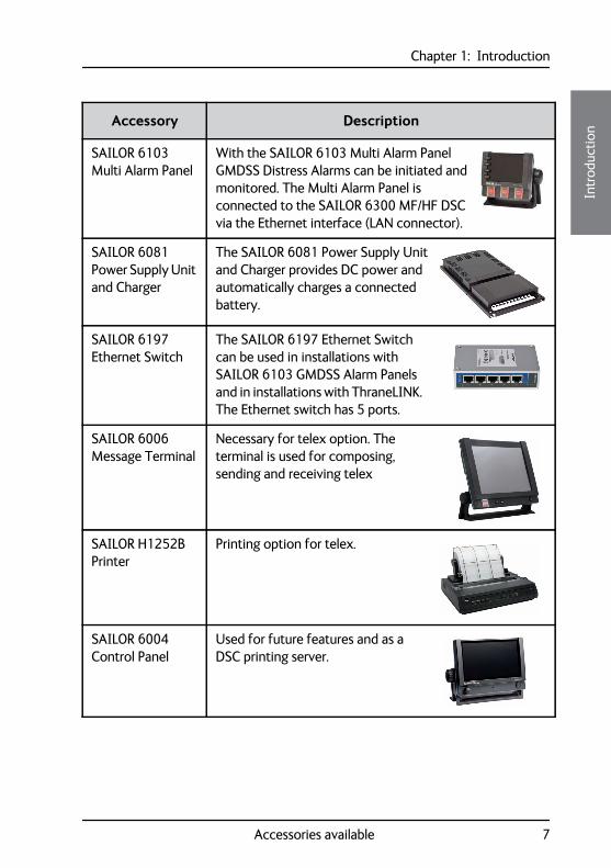
SAILOR 6103 Multi Alarm Panel
With the SAILOR 6103 Multi Alarm Panel GMDSS Distress Alarms can be initiated and monitored. The Multi Alarm Panel is connected to the SAILOR 6300 MF/HF DSC via the Ethernet interface (LAN connector).
SAILOR 6081 Power Supply Unit and Charger
The SAILOR 6081 Power Supply Unit and Charger provides DC power and automatically charges a connected battery.
SAILOR 6197 Ethernet Switch
The SAILOR 6197 Ethernet Switch can be used in installations with SAILOR 6103 GMDSS Alarm Panels and in installations with ThraneLINK. The Ethernet switch has 5 ports.
SAILOR 6006 Message Terminal
Necessary for telex option. The terminal is used for composing, sending and receiving telex
SAILOR H1252B Printer
Printing option for telex.
SAILOR 6004 Control Panel
Used for future features and as a DSC printing server.
Accessory Description
Accessories available 7
Chapter 1: Introduction
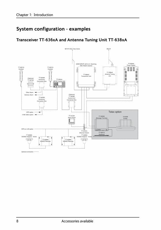
System configuration - examples
Transceiver TT-636xA and Antenna Tuning Unit TT-638xA
TT-6209AAccessory
Connection Box
TT-6209AAccessory
Connection Box
DGNSS ReceiverTT-6588A
DGNSS ReceiverTT-6588A
UnitAntenna Tuning
MF/HF
Handset
TT-638xA
Message Terminal
DSC Watch receiver250W MF/HF with 6 ch. Scanning
TT-636xA
MF/HF DSC Telex Aerial
(Optional)
Keyboard
MF/HF Control UnitTT-630xA
Alarm PanelTT-6103A
Handset
GPS option
2182 select option
TT-6270A
Power SupplyTT-608xA
Connection BoxControl Unit
Distress Alarm
Other Alarm
TT-6201A
Transceiver Unit
TT-6201A
TT-6208A
TT-6001A
TT-6006A
(Optional)
Ethernet SwitchTT-6197A
GPS on LAN option
Optional connection
TT-6286ADGNSS Antenna - Active
TT-6286ADGNSS Antenna - Active
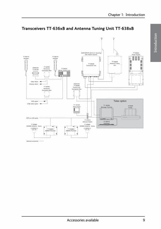
Telex option
PrinterH1252B
8 Accessories available
Chapter 1: Introduction11111
Intr
oduc
tion
Transceivers TT-636xB and Antenna Tuning Unit TT-638xB
TT-6209AAccessory
Connection Box
TT-6209AAccessory
Connection Box
DGNSS ReceiverTT-6588A
DGNSS ReceiverTT-6588A
UnitAntenna Tuning
Tx
Handset
TT-638xB
Message Terminal
DSC Watch receiver250W MF/HF with 6 ch. Scanning
TT-636xB
(Optional)
Keyboard
MF/HF Control UnitTT-630xA
Alarm PanelTT- 6103A
Ethernet SwitchTT-6197A
Handset
GPS option
2182 select option
TT-6270A
Power SupplyTT-608xA
Connection BoxControl Unit
Distress Alarm
Other Alarm
TT-6201A
Transceiver Unit
TT-6201A
TT-6208A
TT-6001A
TT- 6006A
(Optional)
Rx
GPS on LAN option
Optional connection
TT-6286ADGNSS Antenna - Active
TT-6286ADGNSS Antenna - Active
Telex option
PrinterH1252B
Accessories available 9
Chapter 1: Introduction
10 Accessories available
Chapter 222222
Ope
ratio
n
Operation 2
OverviewIn this chapter you find detailed instructions and guidelines for:
• General use and navigation
• Basic MF/HF radio communication
• Watch function
• DSC calls
• Handling multiple calls — DSC and voice
• Phone book
• Replay function
• Setup
General use and navigationWhen the MF/HF radio is powered on for the first time, typically during installation, the vessel’s MMSI number is entered. Hereafter the MMSI number is briefly displayed after power up. The MMSI is a unique, 9-digit identifier assigned to your ship.
Caution! Without a programmed MMSI number the Distress button will not work!
The message NO DSC (NO MMSI) is shown in the DSC window if the MMSI has not been programmed during installation.
11
Chapter 2: Operation
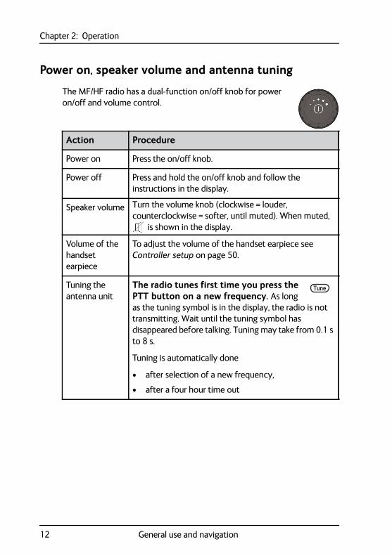
Power on, speaker volume and antenna tuning
The MF/HF radio has a dual-function on/off knob for power on/off and volume control.
Action Procedure
Power on Press the on/off knob.
Power off Press and hold the on/off knob and follow the instructions in the display.
Speaker volume Turn the volume knob (clockwise = louder, counterclockwise = softer, until muted). When muted,
is shown in the display.
Volume of the handset earpiece
To adjust the volume of the handset earpiece see Controller setup on page 50.
Tuning the antenna unit
The radio tunes first time you press the PTT button on a new frequency. As long as the tuning symbol is in the display, the radio is not transmitting. Wait until the tuning symbol has disappeared before talking. Tuning may take from 0.1 s to 8 s.
Tuning is automatically done
• after selection of a new frequency,
• after a four hour time out
Tune
12 General use and navigation
Chapter 2: Operation22222
Ope
ratio
n
SSB, AM BROADCAST, DSC or TELEX mode
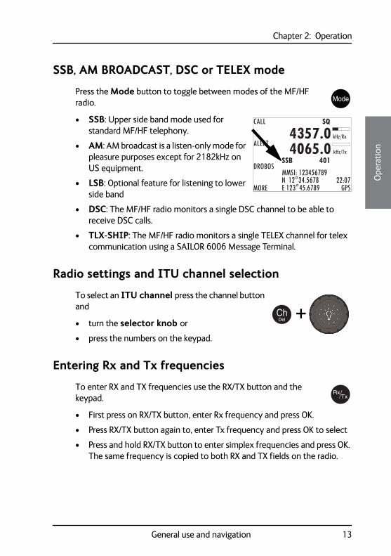
Press the Mode button to toggle between modes of the MF/HF radio.
• SSB: Upper side band mode used for standard MF/HF telephony.
• AM: AM broadcast is a listen-only mode for pleasure purposes except for 2182kHz on US equipment.
• LSB: Optional feature for listening to lower side band
• DSC: The MF/HF radio monitors a single DSC channel to be able to receive DSC calls.
• TLX-SHIP: The MF/HF radio monitors a single TELEX channel for telex communication using a SAILOR 6006 Message Terminal.
Radio settings and ITU channel selection
To select an ITU channel press the channel button and
• turn the selector knob or
• press the numbers on the keypad.
Entering Rx and Tx frequencies
To enter RX and TX frequencies use the RX/TX button and the keypad.
• First press on RX/TX button, enter Rx frequency and press OK.
• Press RX/TX button again to, enter Tx frequency and press OK to select
• Press and hold RX/TX button to enter simplex frequencies and press OK. The same frequency is copied to both RX and TX fields on the radio.
CALL
ALERT
DROBOS
MORE
MMSI: 123456789N 12°34.5678E 123°45.6789 GPS
4357.04065.0
SSB 401
SQ
kHz/Tx
kHz/Rx
22:07
+
General use and navigation 13
Chapter 2: Operation
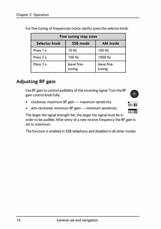
For fine tuning of frequencies (voice clarify) press the selector knob.
Adjusting RF gain
Use RF gain to control audibility of the incoming signal. Turn the RF gain control knob fully:
• clockwise: maximum RF gain — maximum sensitivity
• anti-clockwise: minimum RF gain — minimum sensitivity
The larger the signal strength bar, the larger the signal must be in order to be audible. After entry of a new receive frequency the RF gain is set to maximum.
The function is enabled in SSB telephony and disabled in all other modes.
Fine tuning step sizes
Selector knob SSB mode AM mode
Press 1 x 10 Hz 100 Hz
Press 2 x 100 Hz 1000 Hz
Press 3 x leave fine-tuning
leave fine-tuning
14 General use and navigation
Chapter 2: Operation22222
Ope
ratio
n
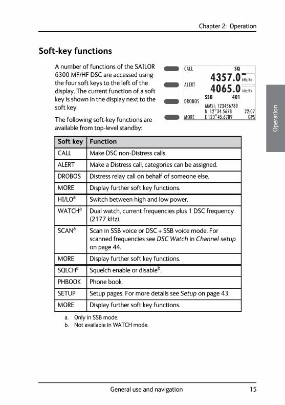
Soft-key functions
A number of functions of the SAILOR 6300 MF/HF DSC are accessed using the four soft keys to the left of the display. The current function of a soft key is shown in the display next to the soft key.
The following soft-key functions are available from top-level standby:
Soft key Function
CALL Make DSC non-Distress calls.
ALERT Make a Distress call, categories can be assigned.
DROBOS Distress relay call on behalf of someone else.
MORE Display further soft key functions.
HI/LOa
a. Only in SSB mode.
Switch between high and low power.
WATCHa Dual watch, current frequencies plus 1 DSC frequency (2177 kHz).
SCANa Scan in SSB voice or DSC + SSB voice mode. For scanned frequencies see DSC Watch in Channel setup on page 44.
MORE Display further soft key functions.
SQLCHa Squelch enable or disableb.
b. Not available in WATCH mode.
PHBOOK Phone book.
SETUP Setup pages. For more details see Setup on page 43.
MORE Display further soft key functions.
CALL
ALERT
DROBOS
MORE
MMSI: 123456789N 12°34.5678E 123°45.6789 GPS
4357.04065.0
SSB 401
SQ
kHz/Tx
kHz/Rx
22:07
General use and navigation 15
Chapter 2: Operation
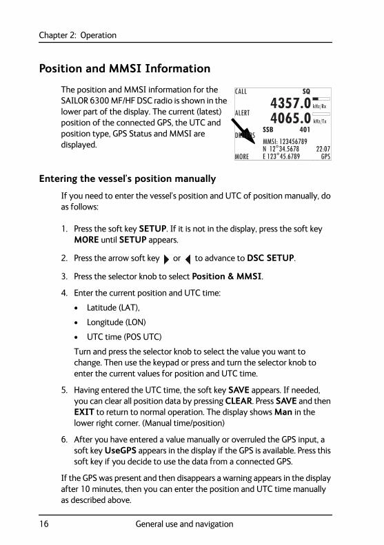
Position and MMSI Information
The position and MMSI information for the SAILOR 6300 MF/HF DSC radio is shown in the lower part of the display. The current (latest) position of the connected GPS, the UTC and position type, GPS Status and MMSI are displayed.
Entering the vessel’s position manually
If you need to enter the vessel’s position and UTC of position manually, do as follows:
1. Press the soft key SETUP. If it is not in the display, press the soft key MORE until SETUP appears.
2. Press the arrow soft key or to advance to DSC SETUP.
3. Press the selector knob to select Position & MMSI.
4. Enter the current position and UTC time:
• Latitude (LAT),
• Longitude (LON)
• UTC time (POS UTC)
Turn and press the selector knob to select the value you want to change. Then use the keypad or press and turn the selector knob to enter the current values for position and UTC time.
5. Having entered the UTC time, the soft key SAVE appears. If needed, you can clear all position data by pressing CLEAR. Press SAVE and then EXIT to return to normal operation. The display shows Man in the lower right corner. (Manual time/position)
6. After you have entered a value manually or overruled the GPS input, a soft key UseGPS appears in the display if the GPS is available. Press this soft key if you decide to use the data from a connected GPS.
If the GPS was present and then disappears a warning appears in the display after 10 minutes, then you can enter the position and UTC time manually as described above.
CALL
ALERT
DROBOS
MORE
MMSI: 123456789N 12°34.5678E 123°45.6789 GPS
4357.04065.0
SSB 401
SQ
kHz/Tx
kHz/Rx
22:07
16 General use and navigation
Chapter 2: Operation22222
Ope
ratio
n
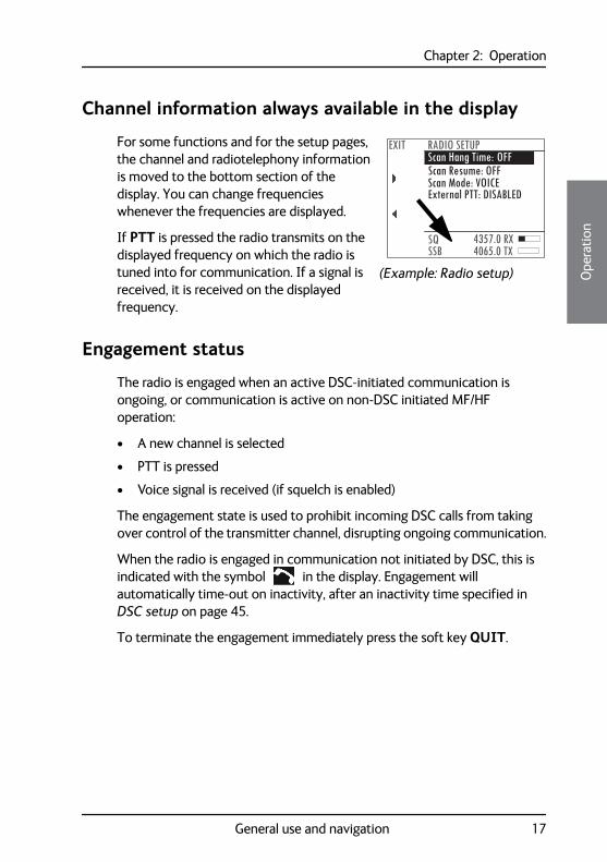
Channel information always available in the display
For some functions and for the setup pages, the channel and radiotelephony information is moved to the bottom section of the display. You can change frequencies whenever the frequencies are displayed.
If PTT is pressed the radio transmits on the displayed frequency on which the radio is tuned into for communication. If a signal is received, it is received on the displayed frequency.
Engagement status
The radio is engaged when an active DSC-initiated communication is ongoing, or communication is active on non-DSC initiated MF/HF operation:
• A new channel is selected
• PTT is pressed
• Voice signal is received (if squelch is enabled)
The engagement state is used to prohibit incoming DSC calls from taking over control of the transmitter channel, disrupting ongoing communication.
When the radio is engaged in communication not initiated by DSC, this is indicated with the symbol in the display. Engagement will automatically time-out on inactivity, after an inactivity time specified in DSC setup on page 45.
To terminate the engagement immediately press the soft key QUIT.
Scan Hang Time: OFFEXIT RADIO SETUP
SSBSQ 4357.0 RX
4065.0 TX
Scan Resume: OFFScan Mode: VOICEExternal PTT: DISABLED
(Example: Radio setup)
General use and navigation 17
Chapter 2: Operation
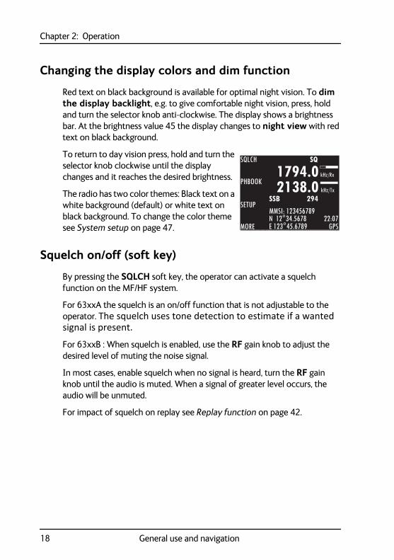
Changing the display colors and dim function
Red text on black background is available for optimal night vision. To dim the display backlight, e.g. to give comfortable night vision, press, hold and turn the selector knob anti-clockwise. The display shows a brightness bar. At the brightness value 45 the display changes to night view with red text on black background.
To return to day vision press, hold and turn the selector knob clockwise until the display changes and it reaches the desired brightness.
The radio has two color themes: Black text on a white background (default) or white text on black background. To change the color theme see System setup on page 47.
Squelch on/off (soft key)
By pressing the SQLCH soft key, the operator can activate a squelch function on the MF/HF system.
For 63xxA the squelch is an on/off function that is not adjustable to the operator. The squelch uses tone detection to estimate if a wanted signal is present.
For 63xxB : When squelch is enabled, use the RF gain knob to adjust the desired level of muting the noise signal.
In most cases, enable squelch when no signal is heard, turn the RF gain knob until the audio is muted. When a signal of greater level occurs, the audio will be unmuted.
For impact of squelch on replay see Replay function on page 42.
SQLCH
PHBOOK
SETUP
MORE
MMSI: 123456789N 12°34.5678E 123°45.6789 GPS
1794.02138.0
SSB 294
SQ
kHz/Tx
kHz/Rx
22:07
18 General use and navigation
Chapter 2: Operation22222
Ope
ratio
n
Basic MF/HF radio communicationYou can make radio calls using the Handset or another speaker device.
• Ship-to-ship communication: Use simplex channels.
• Ship-to-shore communication: Use duplex channels.
Only valid frequencies and channel numbers are accepted.
Selecting SSB telephony frequency
1. Check that the MF/HF radio is in SSB mode. If necessary, press the button MODE to switch to SSB.
2. Enter an RX and TX frequency, for example 2182 kHz, the international calling and Distress frequency for maritime radiotelephone communications on the marine MF bands.
• First press on RX/TX button: Enter Rx frequency.
• Second press on RX/TX button: Enter Tx frequency.
• Long press on selector knob: Edit mode to fine-tune frequencies. In SSB mode (Voice clarify), in 10 Hz steps. One more press changes the step size to 100 Hz.
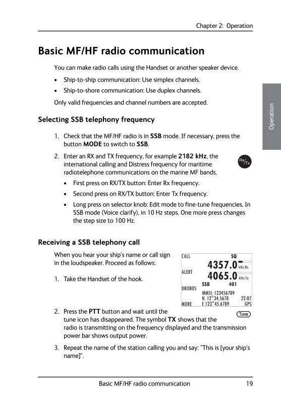
Receiving a SSB telephony call
When you hear your ship’s name or call sign in the loudspeaker. Proceed as follows:
1. Take the Handset of the hook.
2. Press the PTT button and wait until the tune icon has disappeared. The symbol TX shows that the radio is transmitting on the frequency displayed and the transmission power bar shows output power.
3. Repeat the name of the station calling you and say: “This is [your ship’s name]”.
CALL
ALERT
DROBOS
MORE
MMSI: 123456789N 12°34.5678E 123°45.6789 GPS
4357.04065.0
SSB 401
SQ
kHz/Tx
kHz/Rx
22:07
Tune
Basic MF/HF radio communication 19
Chapter 2: Operation
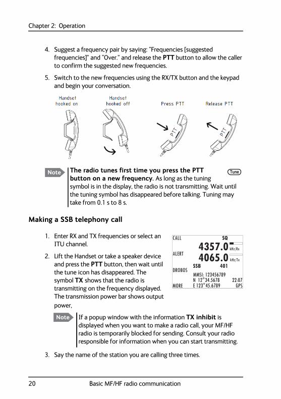
4. Suggest a frequency pair by saying: “Frequencies [suggested frequencies]” and “Over.” and release the PTT button to allow the caller to confirm the suggested new frequencies.
5. Switch to the new frequencies using the RX/TX button and the keypad and begin your conversation.
Making a SSB telephony call
1. Enter RX and TX frequencies or select an ITU channel.
2. Lift the Handset or take a speaker device and press the PTT button, then wait until the tune icon has disappeared. The symbol TX shows that the radio is transmitting on the frequency displayed. The transmission power bar shows output power,
3. Say the name of the station you are calling three times.
Note The radio tunes first time you press the PTT button on a new frequency. As long as the tuning symbol is in the display, the radio is not transmitting. Wait until the tuning symbol has disappeared before talking. Tuning may take from 0.1 s to 8 s.
Tune
CALL
ALERT
DROBOS
MORE
MMSI: 123456789N 12°34.5678E 123°45.6789 GPS
4357.04065.0
SSB 401
SQ
kHz/Tx
kHz/Rx
22:07
Note If a popup window with the information TX inhibit is displayed when you want to make a radio call, your MF/HF radio is temporarily blocked for sending. Consult your radio responsible for information when you can start transmitting.
20 Basic MF/HF radio communication
Chapter 2: Operation22222
Ope
ratio
n
4. Say: “This is [your ship’s name]” and “Over.” and release the PTT button to listen. The symbol RX shows that the radio is receiving on the working channel displayed.
5. When answered, agree upon a pair of frequencies, enter the new frequencies or ITU channel and start talking.
Watch functionThe MF/HF radio has a dual watch function. The currently selected RX and TX frequencies and the routine DSC frequency 2177 kHz are watched.
To start WATCH press the soft key WATCH. The display shows SSB-DW:2177.0 (example).
To stop WATCH press the soft key WATCH.
Watch function 21
Chapter 2: Operation
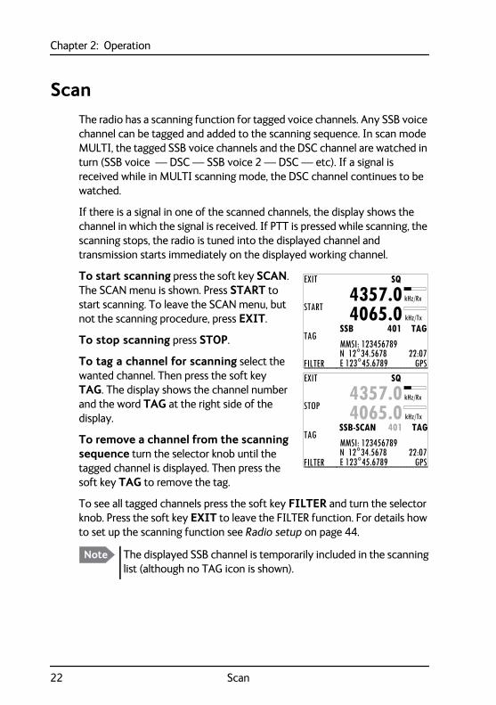
ScanThe radio has a scanning function for tagged voice channels. Any SSB voice channel can be tagged and added to the scanning sequence. In scan mode MULTI, the tagged SSB voice channels and the DSC channel are watched in turn (SSB voice — DSC — SSB voice 2 — DSC — etc). If a signal is received while in MULTI scanning mode, the DSC channel continues to be watched.
If there is a signal in one of the scanned channels, the display shows the channel in which the signal is received. If PTT is pressed while scanning, the scanning stops, the radio is tuned into the displayed channel and transmission starts immediately on the displayed working channel.
To start scanning press the soft key SCAN. The SCAN menu is shown. Press START to start scanning. To leave the SCAN menu, but not the scanning procedure, press EXIT.
To stop scanning press STOP.
To tag a channel for scanning select the wanted channel. Then press the soft key TAG. The display shows the channel number and the word TAG at the right side of the display.
To remove a channel from the scanning sequence turn the selector knob until the tagged channel is displayed. Then press the soft key TAG to remove the tag.
To see all tagged channels press the soft key FILTER and turn the selector knob. Press the soft key EXIT to leave the FILTER function. For details how to set up the scanning function see Radio setup on page 44.
Note The displayed SSB channel is temporarily included in the scanning list (although no TAG icon is shown).
EXIT
START
TAG
FILTER
MMSI: 123456789N 12°34.5678E 123°45.6789 GPS
4357.04065.0
SSB 401 TAG
SQ
kHz/Tx
kHz/Rx
22:07
EXIT
STOP
TAG
FILTER
MMSI: 123456789N 12°34.5678E 123°45.6789 GPS
4357.04065.0
SSB-SCAN 401 TAG
SQ
kHz/Tx
kHz/Rx
22:07
22 Scan
Chapter 2: Operation22222
Ope
ratio
n
DSC callsIn this section of the manual you find information on:
• Own Distress — sending, acknowledging and cancelling
• Sending a Distress from the SAILOR 6103 Multi Alarm Panel
• DROBOS — Distress relay on behalf of someone else
• Receiving Distress calls
• DSC calls
• Printing DSC calls
• Sessions in the MF/HF radio
• Handling multiple calls — DSC and voice
• Geographical area calls
Own Distress — sending, acknowledging and cancelling
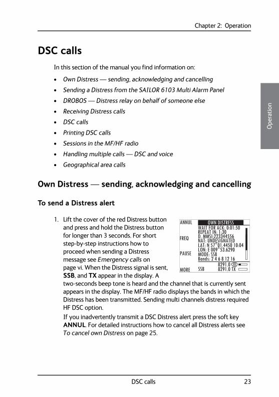
To send a Distress alert
1. Lift the cover of the red Distress button and press and hold the Distress button for longer than 3 seconds. For short step-by-step instructions how to proceed when sending a Distress message see Emergency calls on page vi. When the Distress signal is sent, SSB, and TX appear in the display. A two-seconds beep tone is heard and the channel that is currently sent appears in the display. The MF/HF radio displays the bands in which the Distress has been transmitted. Sending multi channels distress required HF DSC option.If you inadvertently transmit a DSC Distress alert press the soft key ANNUL. For detailed instructions how to cancel all Distress alerts see To cancel own Distress on page 25.
ANNUL
FREQ
MORE
PAUSE
8291.08291.0 TXSSB
OWN DISTRESSWAIT FOR ACK: 0:01:50REPEAT IN: 1:30D. MMSI:223344556NAT: UNDESIGNATEDLAT: N 57°01.4450 10:04LON: E 009°53.6290MODE: SSBBands: 2 4 6 8 12 16
RX
DSC calls 23
Chapter 2: Operation
2. Press the soft key FREQ if you want to specify a certain band out of the 6 available as the next distress frequency. Thereafter all 6 distress frequencies are transmitted.
3. Press the soft key VIEW (press MORE to advance to VIEW) to see details and start radio communication on the frequency 2182 kHz (automatically set) to inform about your Distress situation. (For a HF radio communication the frequency is on 8291 kHz)
For an undesignated Distress message the subsequent communication is always voice communication.
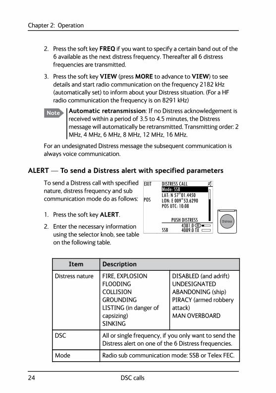
ALERT — To send a Distress alert with specified parameters
To send a Distress call with specified nature, distress frequency and sub communication mode do as follows:
1. Press the soft key ALERT.
2. Enter the necessary information using the selector knob, see table on the following table.
Note Automatic retransmission: If no Distress acknowledgement is received within a period of 3.5 to 4.5 minutes, the Distress message will automatically be retransmitted. Transmitting order: 2 MHz, 4 MHz, 6 MHz, 8 MHz, 12 MHz, 16 MHz.
EXIT
POS
4381.04089.0 TXSSB
DISTRESS CALLMode: SSBLAT: N 57°01.4450LON: E 009°53.6290POS UTC: 10:08
PUSH DISTRESSRX
Item Description
Distress nature FIRE, EXPLOSIONFLOODINGCOLLISIONGROUNDINGLISTING (in danger of capsizing)SINKING
DISABLED (and adrift)UNDESIGNATEDABANDONING (ship)PIRACY (armed robbery attack)MAN OVERBOARD
DSC All or single frequency, if you only want to send the Distress alert on one of the 6 Distress frequencies.
Mode Radio sub communication mode: SSB or Telex FEC.
24 DSC calls
Chapter 2: Operation22222
Ope
ratio
n
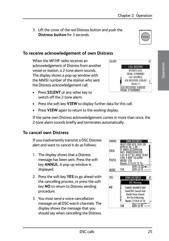
3. Lift the cover of the red Distress button and push the Distress button for 3 seconds.
To receive acknowledgement of own Distress
When the MF/HF radio receives an acknowledgement of Distress from another vessel or station, a 2-tone alarm sounds. The display shows a pop-up window with the MMSI number of the station who sent the Distress acknowledgement call.
• Press SILENT or any other key to switch off the 2-tone alarm.
• Press the soft key VIEW to display further data for this call.
• Press VIEW again to return to the working display.
If the same own Distress acknowledgement comes in more than once, the 2-tone alarm sounds briefly and terminates automatically.
To cancel own Distress
If you inadvertently transmit a DSC Distress alert and want to cancel it do as follows:
1. The display shows that a Distress message has been sent. Press the soft key ANNUL. A pop-up window is displayed.
2. Press the soft key YES to go ahead with the cancelling process, or press the soft key NO to return to Distress sending procedure.
3. You must send a voice cancellation message on all DSC watch channels. The display shows the message that you should say when cancelling the Distress.
SSB
SILENT
FROM: 219380005CACK RECEIVED: 0:00:03
DISTRESS ACK.FROM: 219380005
CAT: DISTRESSACK RECEIVED: 0:00:03
Bands: 2
CALL RECEIVED
ANNUL
FREQ
MORE
PAUSE
8291.08291.0 TXSSB
OWN DISTRESSWAIT FOR ACK: 0:01:50REPEAT IN: 1:30D. MMSI:223344556NAT: UNDESIGNATEDLAT: N 57°01.4450 10:04LON: E 009°53.6290MODE: SSBBands: 2 4 6 8 12 16
RX
YES
NO
8291.08291.0 TXSSB
OWN DISTRESSWAIT FOR ACK: 0:01:50REPEAT IN: 1:30D. MMSI:223344556NAT: UNDESIGNATEDLAT: N 57°01.4450 10:04LON: E 009°53.6290MODE: SSBBands: 2 4 6 8 12 16
RX
CANSEL DISTRESS WillSend DSC Cancel AndGuide Voice CancelOn The Following
Bands: 2 4 6 8 12 16
DSC Warning
DSC calls 25
Chapter 2: Operation
Use the selector knob to scroll through all information for the voice cancel.
4. Press the soft key OK to go to the next Distress frequency and repeat step 3. Once you have made the voice cancel for all Distress frequencies, Own Distress is cancelled.
5. To finish the Distress session and get back to normal radio use press the soft key QUIT.
Power failure while in Distress
In case of a power failure or switch-off during the transmission of a Distress the SAILOR 6300 MF/HF DSC gives an audible warning after power-up and automatically resumes sending Distress 10 seconds after power up. Within the 10 seconds you have the following options:
• Press QUIT to terminate the active Distress procedure (acknowledged or unacknowledged).
• Press RESUME (or do nothing) to resume the sending Distress procedure.
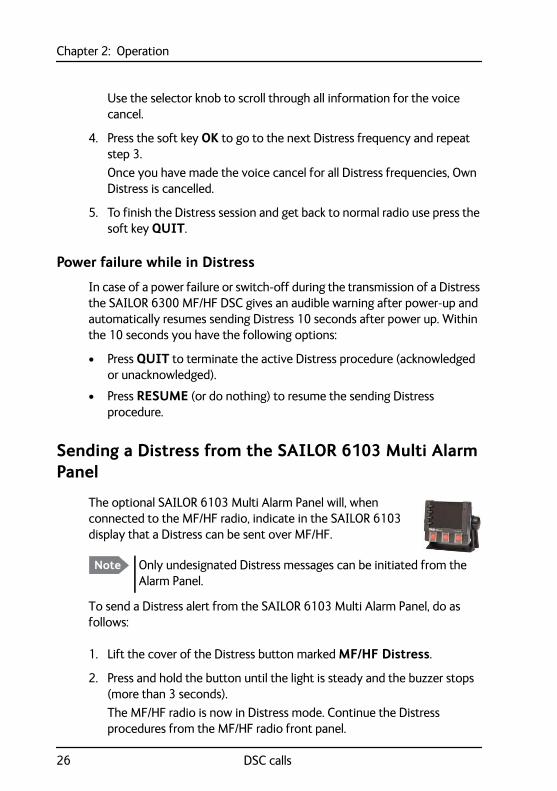
Sending a Distress from the SAILOR 6103 Multi Alarm Panel
The optional SAILOR 6103 Multi Alarm Panel will, when connected to the MF/HF radio, indicate in the SAILOR 6103 display that a Distress can be sent over MF/HF.
To send a Distress alert from the SAILOR 6103 Multi Alarm Panel, do as follows:
1. Lift the cover of the Distress button marked MF/HF Distress.
2. Press and hold the button until the light is steady and the buzzer stops (more than 3 seconds).The MF/HF radio is now in Distress mode. Continue the Distress procedures from the MF/HF radio front panel.
Note Only undesignated Distress messages can be initiated from the Alarm Panel.
26 DSC calls
Chapter 2: Operation22222
Ope
ratio
n
3. Press the MUTE button on the Alarm panel to mute the audible alarm for current distress. All audible alarms are muted.
For further information see the Alarm Panel Installation and user manual.
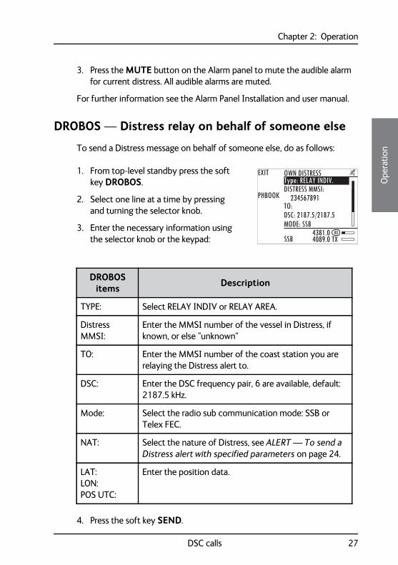
DROBOS — Distress relay on behalf of someone else
To send a Distress message on behalf of someone else, do as follows:
1. From top-level standby press the soft key DROBOS.
2. Select one line at a time by pressing and turning the selector knob.
3. Enter the necessary information using the selector knob or the keypad:
4. Press the soft key SEND.
DROBOS items Description
TYPE: Select RELAY INDIV or RELAY AREA.
Distress MMSI:
Enter the MMSI number of the vessel in Distress, if known, or else “unknown”
TO: Enter the MMSI number of the coast station you are relaying the Distress alert to.
DSC: Enter the DSC frequency pair, 6 are available, default: 2187.5 kHz.
Mode: Select the radio sub communication mode: SSB or Telex FEC.
NAT: Select the nature of Distress, see ALERT — To send a Distress alert with specified parameters on page 24.
LAT:LON:POS UTC:
Enter the position data.
EXIT
PHBOOK
4381.04089.0 TXSSB
OWN DISTRESSType: RELAY INDIV.DISTRESS MMSI:
234567891TO:DSC: 2187.5/2187.5MODE: SSB
RX
DSC calls 27
Chapter 2: Operation
Receiving Distress calls
When the radio receives a Distress call, the 2-tone alarm sounds. The display shows the bands in which the Distress call is received and the category of the Distress call. The types of Distress calls are Distress, Distress ACK, Distress RELAY and DISTR. RELAY ACK.
1. Press the soft key SILENT to switch off the 2-tone alarm.
2. Press VIEW to display further information for this call.
3. Press HOLD to put the call on hold and stay in the communication loop to receive follow up information, updates etc.
4. Monitor radio communication on the frequency 2182 kHz (automatically set) as a coast station may require your assistance.(If Distress is received on HF radio communication, the frequency is 8291 kHz)
5. The radio receives the first Distress acknowledgement call and the 2-tone alarm sounds again. To switch off the 2-tone alarm press the soft key SILENT.
6. If you decide to acknowledge the Distress call press the soft key ACK (press MORE until ACK is shown in the display).
You can also relay the Distress call. Enter a new MMSI to which you want to send the Distress call, then press the soft key SEND.
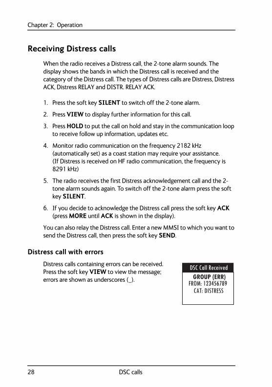
Distress call with errors
Distress calls containing errors can be received. Press the soft key VIEW to view the message; errors are shown as underscores (_).
DSC Call ReceivedGROUP (ERR)
FROM: 123456789CAT: DISTRESS
28 DSC calls
Chapter 2: Operation22222
Ope
ratio
n
Distress call log
As long as you are part of a Distress session, i.e. you have not pressed QUIT, you receive Distress messages and can track all Distress messages for the current Distress event.
1. Press the soft key LOG. If it is not in the display, press the soft key MORE until LOG appears.
2. Press the soft key NEXT and PREV to browse the received Distress messages.
3. Press the soft key EXIT to leave the log.
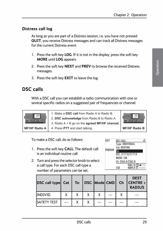
DSC calls
With a DSC call you can establish a radio communication with one or several specific radios on a suggested pair of frequencies or channel.
To make a DSC call, do as follows:
1. Press the soft key CALL. The default call is an individual routine call.
2. Turn and press the selector knob to select a call type. For each DSC call type a number of parameters can be set.
1. Make a DSC call from Radio A to Radio B.2. DSC acknowledge from Radio B to Radio A.3. Radio A + B go on the agreed MF/HF channel.4. Press PTT and start talking.MF/HF Radio A MF/HF Radio B
EXIT
PHBOOK
4381.04089.0 TXSSB
DSC CALLType: INDIVIDUALCat: ROUTINETo:DSC: 2177.0/2177.0MODE: SSBCh: 2265.0/2265.0
RX
DSC call type Cat To: DSC: Mode CMD ChDEST
CENTRE + RADIUS
INDIVID. X X X X — X —
SATETY TEST — X X — — — —
DSC calls 29
Chapter 2: Operation
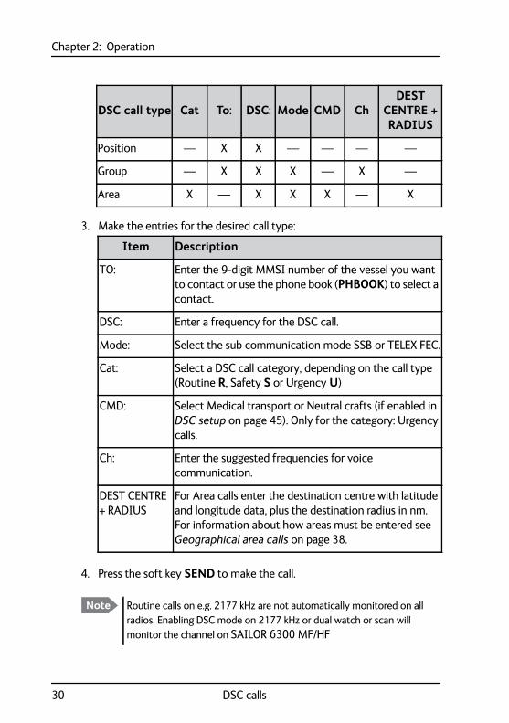
3. Make the entries for the desired call type:
4. Press the soft key SEND to make the call.
Position — X X — — — —
Group — X X X — X —
Area X — X X X — X
DSC call type Cat To: DSC: Mode CMD ChDEST
CENTRE + RADIUS
Item Description
TO: Enter the 9-digit MMSI number of the vessel you want to contact or use the phone book (PHBOOK) to select a contact.
DSC: Enter a frequency for the DSC call.
Mode: Select the sub communication mode SSB or TELEX FEC.
Cat: Select a DSC call category, depending on the call type (Routine R, Safety S or Urgency U)
CMD: Select Medical transport or Neutral crafts (if enabled in DSC setup on page 45). Only for the category: Urgency calls.
Ch: Enter the suggested frequencies for voice communication.
DEST CENTRE + RADIUS
For Area calls enter the destination centre with latitude and longitude data, plus the destination radius in nm. For information about how areas must be entered see Geographical area calls on page 38.
Note Routine calls on e.g. 2177 kHz are not automatically monitored on all radios. Enabling DSC mode on 2177 kHz or dual watch or scan will monitor the channel on SAILOR 6300 MF/HF
30 DSC calls
Chapter 2: Operation22222
Ope
ratio
n
Printing DSC calls
If a printer is connected to the SAILOR 6300 MF/HF DSC via LAN you can print DSC messages automatically. You can also print entire DSC call logs.
To set up a default printer, do as follows:
1. Go to SETUP and use the arrow keys to advance to System Setup
2. Select Printer Config:.
3. Select one printer as the default printer and press the selector knob to enter the choice.
To print DSC messages, do as follows:
1. Go to SETUP and use the arrow keys to advance to DSC Setup.
2. Use the selector wheel to scroll to Print DSC.
3. Set Print DSC: to ON.
To print DSC call logs, do as follows:
1. Go to SETUP and use the arrow keys to advance to DSC call logs.
2. Select the call log you want to print.
3. Press the soft key PRINT.
A printer attached to the SAILOR 6004 Control panel can be used, or a generic LAN based line printer.
Note For 6000B:
DSC logs can also be downloaded accessing the IP address of the radio with a standard web browser.
DSC calls 31
Chapter 2: Operation
32 DSC calls
Sessions in the MF/HF radio
What is a session?
A DSC session is defined as a collection of DSC calls (transmitted and/or received) that are related to the same event (e.g. a Distress event) or established call (e.g. an individual call request followed by an acknowledgement).
A session can be either active or on hold. The active session has control over the radio transmitter. A session can have a purpose. For example if the purpose is to establish a communication on a working channel.
The non-DSC communication (voice) is considered as a session that can be active (engaged) or on hold (dis-engaged). See also Engagement status on page 17.
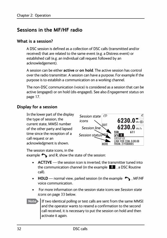
Display for a session
In the lower part of the display the type of session, the current state, MMSI number of the other party and lapsed time since the reception of a call request or an acknowledgment is shown.
The session state icons, in the example and R, show the state of the session:
• ACTIVE — the session icon is inverted, the transmitter tuned into the communication channel (in the example , a DSC Routine call).
• HOLD — normal view, parked session (in the example , MF/HF voice communication.
• For more information on the session state icons see Session state icons on page 33 below.
Note If two identical polling or test calls are sent from the same MMSI and the operator wants to resend a confirmation to the second call received, it is necessary to put the session on hold and then activate it again.
QUIT
HOLD
MORE
GROUP RXLINK FOR COM: 0:00:08FROM: 219380005
6230.06230.0
SSB 611kHz/Tx
kHz RX
R
Session state
Session line
Session status
icons
Chapter 2: Operation22222
Ope
ratio
n
Session state icons
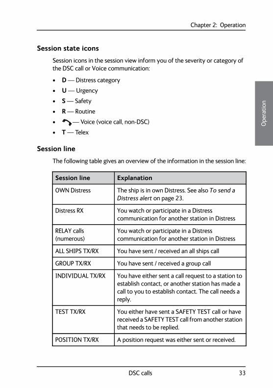
Session icons in the session view inform you of the severity or category of the DSC call or Voice communication:
• D — Distress category
• U — Urgency
• S — Safety
• R — Routine
• — Voice (voice call, non-DSC)
• T — Telex
Session line
The following table gives an overview of the information in the session line:
Session line Explanation
OWN Distress The ship is in own Distress. See also To send a Distress alert on page 23.
Distress RX You watch or participate in a Distress communication for another station in Distress
RELAY calls (numerous)
You watch or participate in a Distress communication for another station in Distress
ALL SHIPS TX/RX You have sent / received an all ships call
GROUP TX/RX You have sent / received a group call
INDIVIDUAL TX/RX You have either sent a call request to a station to establish contact, or another station has made a call to you to establish contact. The call needs a reply.
TEST TX/RX You either have sent a SAFETY TEST call or have received a SAFETY TEST call from another station that needs to be replied.
POSITION TX/RX A position request was either sent or received.
DSC calls 33
Chapter 2: Operation
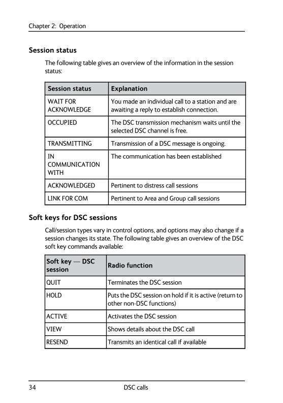
Session status
The following table gives an overview of the information in the session status:
Soft keys for DSC sessions
Call/session types vary in control options, and options may also change if a session changes its state. The following table gives an overview of the DSC soft key commands available:
Session status Explanation
WAIT FOR ACKNOWLEDGE
You made an individual call to a station and are awaiting a reply to establish connection.
OCCUPIED The DSC transmission mechanism waits until the selected DSC channel is free.
TRANSMITTING Transmission of a DSC message is ongoing.
IN COMMUNICATION WITH
The communication has been established
ACKNOWLEDGED Pertinent to distress call sessions
LINK FOR COM Pertinent to Area and Group call sessions
Soft key — DSC session Radio function
QUIT Terminates the DSC session
HOLD Puts the DSC session on hold if it is active (return to other non-DSC functions)
ACTIVE Activates the DSC session
VIEW Shows details about the DSC call
RESEND Transmits an identical call if available
34 DSC calls
Chapter 2: Operation22222
Ope
ratio
n
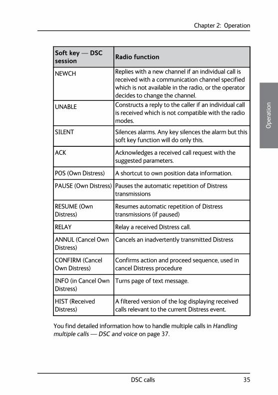
You find detailed information how to handle multiple calls in Handling multiple calls — DSC and voice on page 37.
NEWCH Replies with a new channel if an individual call is received with a communication channel specified which is not available in the radio, or the operator decides to change the channel.
UNABLE Constructs a reply to the caller if an individual call is received which is not compatible with the radio modes.
SILENT Silences alarms. Any key silences the alarm but this soft key function will do only this.
ACK Acknowledges a received call request with the suggested parameters.
POS (Own Distress) A shortcut to own position data information.
PAUSE (Own Distress) Pauses the automatic repetition of Distress transmissions
RESUME (Own Distress)
Resumes automatic repetition of Distress transmissions (if paused)
RELAY Relay a received Distress call.
ANNUL (Cancel Own Distress)
Cancels an inadvertently transmitted Distress
CONFIRM (Cancel Own Distress)
Confirms action and proceed sequence, used in cancel Distress procedure
INFO (in Cancel Own Distress)
Turns page of text message.
HIST (Received Distress)
A filtered version of the log displaying received calls relevant to the current Distress event.
Soft key — DSC session Radio function
DSC calls 35
Chapter 2: Operation
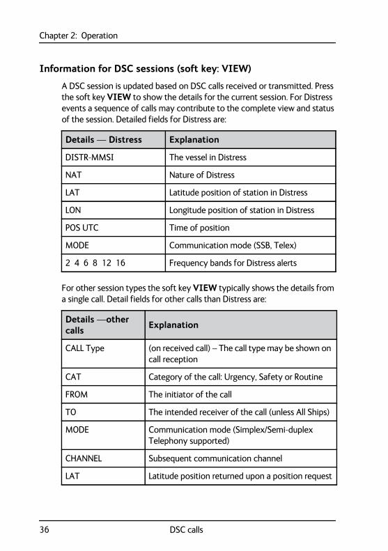
Information for DSC sessions (soft key: VIEW)
A DSC session is updated based on DSC calls received or transmitted. Press the soft key VIEW to show the details for the current session. For Distress events a sequence of calls may contribute to the complete view and status of the session. Detailed fields for Distress are:
For other session types the soft key VIEW typically shows the details from a single call. Detail fields for other calls than Distress are:
Details — Distress Explanation
DISTR-MMSI The vessel in Distress
NAT Nature of Distress
LAT Latitude position of station in Distress
LON Longitude position of station in Distress
POS UTC Time of position
MODE Communication mode (SSB, Telex)
2 4 6 8 12 16 Frequency bands for Distress alerts
Details —other calls Explanation
CALL Type (on received call) – The call type may be shown on call reception
CAT Category of the call: Urgency, Safety or Routine
FROM The initiator of the call
TO The intended receiver of the call (unless All Ships)
MODE Communication mode (Simplex/Semi-duplex Telephony supported)
CHANNEL Subsequent communication channel
LAT Latitude position returned upon a position request
36 DSC calls
Chapter 2: Operation22222
Ope
ratio
n
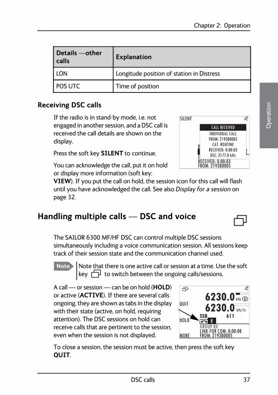
Receiving DSC callsIf the radio is in stand-by mode, i.e. not engaged in another session, and a DSC call is received the call details are shown on the display.
Press the soft key SILENT to continue.
You can acknowledge the call, put it on hold or display more information (soft key: VIEW). If you put the call on hold, the session icon for this call will flash until you have acknowledged the call. See also Display for a session on page 32.
Handling multiple calls — DSC and voice
The SAILOR 6300 MF/HF DSC can control multiple DSC sessions simultaneously including a voice communication session. All sessions keep track of their session state and the communication channel used.
A call — or session — can be on hold (HOLD) or active (ACTIVE). If there are several calls ongoing, they are shown as tabs in the display with their state (active, on hold, requiring attention). The DSC sessions on hold can receive calls that are pertinent to the session, even when the session is not displayed.
To close a session, the session must be active, then press the soft key QUIT.
LON Longitude position of station in Distress
POS UTC Time of position
Details —other calls Explanation
DCS
SILENT
FROM: 219380005INRECEIVED: 0:00:03
INDIVIDUAL CALLFROM: 219380005
CAT: ROUTINERECEIVED: 0:00:03DSC: 2177.0 kHz
CALL RECEIVED
Note Note that there is one active call or session at a time. Use the soft key to switch between the ongoing calls/sessions.
QUIT
HOLD
MORE
GROUP RXLINK FOR COM: 0:00:08FROM: 219380005
6230.06230.0
SSB 611kHz/Tx
kHz RX
R
DSC calls 37
Chapter 2: Operation
In case there are simultaneous alarms, they are sorted according to their priorities, the most important ones are shown first. In some cases alarm or pop-up messages terminate automatically, then the display messages and audible alarms also disappear automatically.
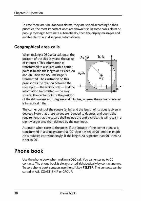
Geographical area calls
When making a DSC area call, enter the position of the ship (x,y) and the radius of interest r. This information is transformed to a square with a corner point (a,b) and the length of its sides, a and b. Then the DSC message is transmitted. The illustration on this page shows the relation between the user input — the white circle — and the information transmitted —the grey square. The center point is the position of the ship measured in degrees and minutes, whereas the radius of interest is in nautical miles.
The corner point of the square (a2,b2) and the length of its sides is given in degrees. Note that these values are rounded to degrees, and due to the requirement that the square shall include the entire circle; this will result in a slightly larger area than defined by the user input.
Attention when close to the poles: If the latitude of the corner point ‘a’ is transformed to a value greater that 90° then it is set to 90° and the length b is reduced correspondingly. If the length a is greater than 90° then a is set to 90°.
Phone bookUse the phone book when making a DSC call. You can enter up to 50 contacts. The phone book is always sorted alphabetically by contact names. To sort phone book contacts use the soft key FILTER. The contacts can be sorted in ALL, COAST, SHIP or GROUP.
38 Phone book
Chapter 2: Operation22222
Ope
ratio
n
Using the phone book to make a DSC call
To call a contact using the phone book do as follows:
1. Press the soft key CALL. If it is not in the display, press the soft key MORE until CALL appears. The DSC call composer is shown in the display.
2. Press the soft key PHBOOK.
3. Turn the selector knob to scroll to the phone book entry that you want to call and press the selector knob to select the contact.
4. Press the soft key SEND to make the call.
Adding a contact to the phone book
To add a contact to the phone book do as follows:
1. Press the soft key PHBOOK. If it is not in the display, press the soft key MORE until PHBOOK appears in the display.
2. Press the soft key ADD and fill in the details for the new contact.
Contact Description
NAME Enter the name by turning the selector knob to the desired letter, press the selector knob to accept the letter and advance to the next letter. To finish press the soft key OK.
TYPE Press and turn the selector knob to select SHIP, GROUP or COAST STATION.
MMSI Turn and press the selector knob to enter the contact’s MMSI number (9 digits), press the soft key OK to accept. For coast station contacts you can also enter a DSC channel.
Ch (optional) Press and turn the selector knob to select the preferred channel for this contact, press the soft key OK.
Phone book 39
Chapter 2: Operation
3. Press the soft key SAVE to save the contact information.
4. Press the soft key EXIT to leave the phone book.
Editing a contact
1. Press the soft key PHBOOK. If it is not in the display, press the soft key MORE until PHBOOK appears.
2. Press the soft key EDIT.
3. Press and turn the selector knob to browse through the details of the contact and continue as described in Adding a contact to the phone book from step 2 onwards.
Deleting a contact
1. Press the soft key PHBOOK. If it is not in the display, press the soft key MORE until PHBOOK appears.
2. Turn the selector knob to browse to the contact you want to delete.
3. Press the soft key MORE until DELETE appears.
4. Press the soft key DELETE.
5. Press EXIT to leave the phone book and return to radio operation.
Position Auto Ack
For SHIP or COAST STATION: Press and turn the selector knob to select YES or NO for this contact, press the soft key OK. This will allow auto-ack of position requests for this contact.
Listen to Group
For GROUP: Press and turn the selector knob to select YES or NO for this contact, press the soft key OK. The radio will respond to calls to the specified group.
Contact Description
40 Phone book
Chapter 2: Operation22222
Ope
ratio
n
RadiotelexWith the Radiotelex system you can send and receive telex messages over MF/HF radio. The Radiotelex program runs on a SAILOR 6006 Message Terminal with a keyboard. The SAILOR 6006 is connected to a System 6000 MF/HF radio, which transmits and receives the radio telex messages.
In order to send and receive telex messages press the mode button of the MF/HF radio until TLX-SHIP is shown in the display.
For detailed instructions on how to send a radio telex message see the SAILOR 6300 MF/HF Radiotelex, User Manual.
Radiotelex 41
Chapter 2: Operation
Replay function
With replay you can playback received voice messages in the loudspeaker. Recording is activated automatically when a signal is received. Recording is not possible during playback. Up to 60 tracks or 240 seconds can be handled.
The recorded channel is displayed and the message length is shown in seconds. The display shows also how old the message is. If the 240 s storage limit is reached, the oldest data is overwritten.
Replaying recorded messages
Press the replay button to replay a recorded message. The latest message is repeated. Information about this message is shown in the display. If a signal is received while in replay mode the display shows in the display.
To stop replaying the message press the soft key STOP. To skip through all recorded messages press the replay button repeatedly at short intervals.
Note To record messages only (without the continuous background noise) activate the squelch function. Press the soft key SQLCH.
Note The replay function can be started even in a Distress situation. If a DSC call is received the replay function continues the playback.
42 Replay function
Chapter 2: Operation22222
Ope
ratio
n
SetupThe following setup pages are described in this section of the manual:
• Radio setup
• Channel setup
• Power Supply
• DSC setup
• DSC call logs
• System setup
• Controller setup
• Diagnostics
• System config
Accessing a setup page
To change a setting in one of the SETUP pages, do as follows
1. Press the soft key SETUP. If it is not in the display, press the soft key MORE until SETUP appears.
2. Press the arrow soft key or to advance to the SETUP page you want to edit.
3. Turn the selector knob to go to a setting, then press the selector knob to change the setting.
4. Press EXIT to return to normal radio operation.
Setup 43
Chapter 2: Operation
Radio setup
Channel setup
Item Description
Scan Hang Time
Scan hang time, in seconds on an active receiving working channel. The time is measured from the signal is detected. The radio remains on the channel for the set time interval, if a signal was detected.
OFF: Resumes scanning when signal disappears (default)4, 6, 8, 10: Hang time in seconds.
Scan Resume
Scan resume time, in seconds. When the programmed time of inactivity has elapsed, and when watch/scan has been aborted using a press on PTT, or after power-up, scan or watch is resumed.
OFF: Automatic resume is deactivated (default)3, 6, 10, 15, 20, 25, 30: Resume time in seconds.
Scan Mode
Scan mode when pressing the soft key SCAN:— VOICE (SSB voice) or — MULTI (DSC plus SSB voice, alternating)
External PTT
ENABLED (For use of an external PTT device, connected to the TU AUX plug) or DISABLED
Item Description
Watch Receiver
Press the selector knob to display the watch frequencies and to show which of these are enabled. Contact your local distributor for modifications.
Private Channels
Read only. Contact your local distributor for adding private channels.
DSC Watch
The frequency watched for dual watch or multi scan. To receive routine DSC calls set this frequency to 2177.
44 Setup
Chapter 2: Operation22222
Ope
ratio
n
Power Supply
DSC setup
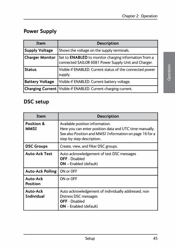
Item Description
Supply Voltage Shows the voltage on the supply terminals.
Charger Monitor Set to ENABLED to monitor charging information from a connected SAILOR 6081 Power Supply Unit and Charger.
Status Visible if ENABLED. Current status of the connected power supply.
Battery Voltage Visible if ENABLED. Current battery voltage.
Charging Current Visible if ENABLED. Current charging current.
Item Description
Position & MMSI
Available position information.Here you can enter position data and UTC time manually. See also Position and MMSI Information on page 16 for a step-by-step description.
DSC Groups Create, view, and filter DSC groups.
Auto-Ack Test Auto-acknowledgement of test DSC messagesOFF - DisabledON – Enabled (default)
Auto-Ack Polling ON or OFF
Auto-Ack Position
ON or OFF
Auto-Ack Individual
Auto acknowledgement of individually addressed, non Distress DSC messagesOFF - DisabledON – Enabled (default)
Setup 45
Chapter 2: Operation
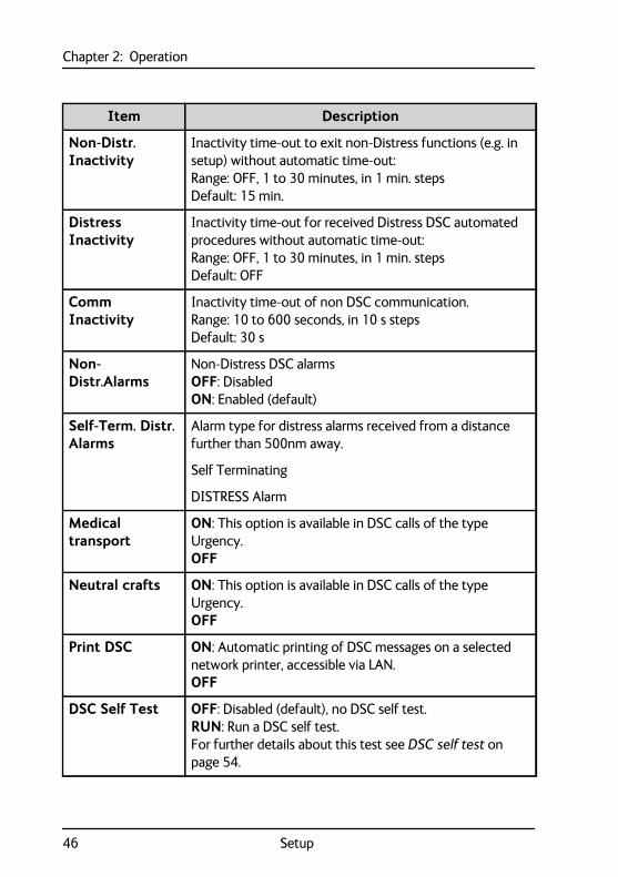
Non-Distr. Inactivity
Inactivity time-out to exit non-Distress functions (e.g. in setup) without automatic time-out:Range: OFF, 1 to 30 minutes, in 1 min. stepsDefault: 15 min.
Distress Inactivity
Inactivity time-out for received Distress DSC automated procedures without automatic time-out:Range: OFF, 1 to 30 minutes, in 1 min. stepsDefault: OFF
Comm Inactivity
Inactivity time-out of non DSC communication.Range: 10 to 600 seconds, in 10 s stepsDefault: 30 s
Non-Distr.Alarms
Non-Distress DSC alarmsOFF: DisabledON: Enabled (default)
Self-Term. Distr. Alarms
Alarm type for distress alarms received from a distance further than 500nm away.
Self Terminating
DISTRESS Alarm
Medical transport
ON: This option is available in DSC calls of the type Urgency.OFF
Neutral crafts ON: This option is available in DSC calls of the type Urgency.OFF
Print DSC ON: Automatic printing of DSC messages on a selected network printer, accessible via LAN.OFF
DSC Self Test OFF: Disabled (default), no DSC self test.RUN: Run a DSC self test.For further details about this test see DSC self test on page 54.
Item Description
46 Setup
Chapter 2: Operation22222
Ope
ratio
n
DSC call logs
System setup
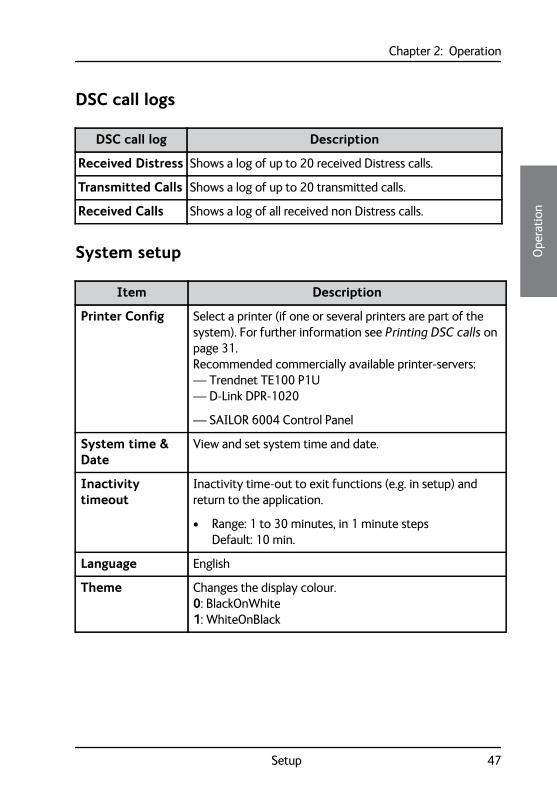
DSC call log Description
Received Distress Shows a log of up to 20 received Distress calls.
Transmitted Calls Shows a log of up to 20 transmitted calls.
Received Calls Shows a log of all received non Distress calls.
Item Description
Printer Config Select a printer (if one or several printers are part of the system). For further information see Printing DSC calls on page 31.Recommended commercially available printer-servers:— Trendnet TE100 P1U— D-Link DPR-1020
— SAILOR 6004 Control Panel
System time & Date
View and set system time and date.
Inactivity timeout
Inactivity time-out to exit functions (e.g. in setup) and return to the application.
• Range: 1 to 30 minutes, in 1 minute stepsDefault: 10 min.
Language English
Theme Changes the display colour.0: BlackOnWhite1: WhiteOnBlack
Setup 47
Chapter 2: Operation
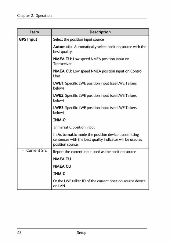
GPS Input Select the position input source
Automatic: Automatically select position source with the best quality.
NMEA TU: Low speed NMEA position input on Transceiver
NMEA CU: Low speed NMEA position input on Control Unit
LWE1: Specific LWE position input (see LWE Talkers below)
LWE2: Specific LWE position input (see LWE Talkers below)
LWE3: Specific LWE position input (see LWE Talkers below)
INM-C:
Inmarsat C position input
In Automatic mode the position device transmitting sentences with the best quality indicator will be used as position source.
- Current Src Report the current input used as the position source
NMEA TU
NMEA CU
INM-C
Or the LWE talker ID of the current position source device on LAN
Item Description
48 Setup
Chapter 2: Operation22222
Ope
ratio
n
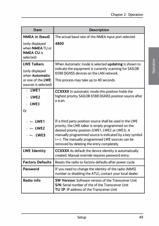
NMEA in (baud)
(only displayed when NMEA TU or NMEA CU is selected)
The actual baud rate of the NMEA input port selected
4800
LWE Talkers
(only displayed when Automatic or one of the LWE sources is selected)
When Automatic mode is selected updating is shown to indicate the equipment is currently scanning for SAILOR 6588 DGNSS devices on the LAN network.
This process may take up to 40 seconds.
- LWE1
- LWE2
- LWE3
Or
- LWE1
- LWE2
- LWE3
CCXXXX In automatic mode this position holds the highest priority SAILOR 6588 DGNSS position source after a scan.
If a third party position source shall be used in the LWE priority, the LWE talker is simply programmed on the desired priority position (LWE1, LWE2 or LWE3). A manually programmed source is indicated by a key symbol (). The manually programmed LWE sources can be removed by deleting the entry completely.
LWE Identity CCXXXX As default the device identity is automatically created. Manual override requires password entry.
Factory Defaults Resets the radio to factory defaults after power cycle.
Password If you need to change the identity of the radio (MMSI number or disabling the ATU), contact your local dealer.
Radio info SW Version: Software version of the Transceiver UnitS/N: Serial number of the of the Transceiver UnitTU IP: IP address of the Transceiver Unit
Item Description
Setup 49
Chapter 2: Operation
Controller setup
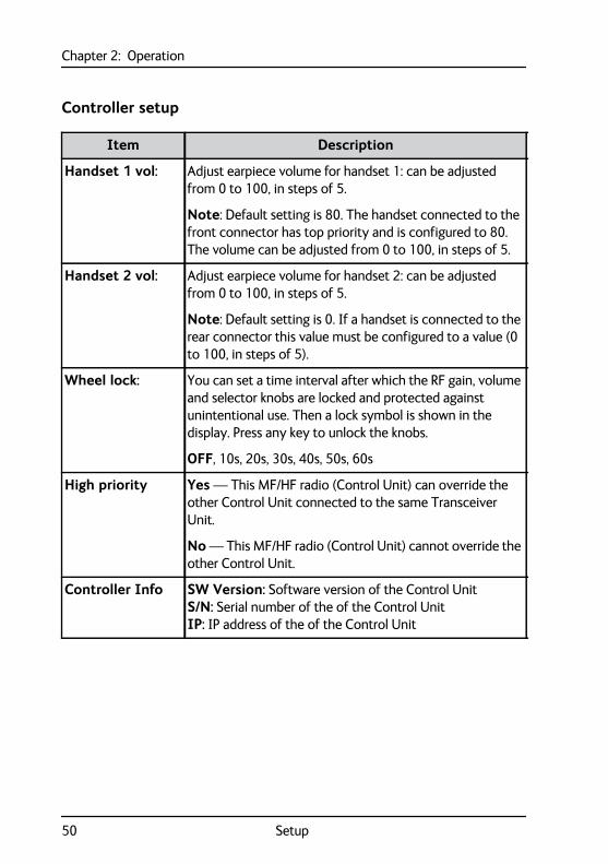
Item Description
Handset 1 vol: Adjust earpiece volume for handset 1: can be adjusted from 0 to 100, in steps of 5.
Note: Default setting is 80. The handset connected to the front connector has top priority and is configured to 80. The volume can be adjusted from 0 to 100, in steps of 5.
Handset 2 vol: Adjust earpiece volume for handset 2: can be adjusted from 0 to 100, in steps of 5.
Note: Default setting is 0. If a handset is connected to the rear connector this value must be configured to a value (0 to 100, in steps of 5).
Wheel lock: You can set a time interval after which the RF gain, volume and selector knobs are locked and protected against unintentional use. Then a lock symbol is shown in the display. Press any key to unlock the knobs.
OFF, 10s, 20s, 30s, 40s, 50s, 60s
High priority Yes — This MF/HF radio (Control Unit) can override the other Control Unit connected to the same Transceiver Unit.
No — This MF/HF radio (Control Unit) cannot override the other Control Unit.
Controller Info SW Version: Software version of the Control UnitS/N: Serial number of the of the Control UnitIP: IP address of the of the Control Unit
50 Setup
Chapter 2: Operation22222
Ope
ratio
n
Diagnostics
System config
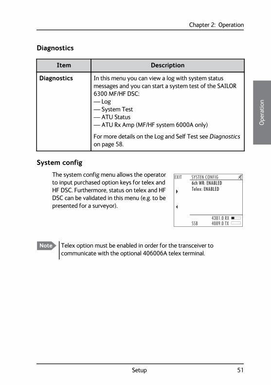
The system config menu allows the operator to input purchased option keys for telex and HF DSC. Furthermore, status on telex and HF DSC can be validated in this menu (e.g. to be presented for a surveyor).
Item Description
Diagnostics In this menu you can view a log with system status messages and you can start a system test of the SAILOR 6300 MF/HF DSC:— Log— System Test— ATU Status— ATU Rx Amp (MF/HF system 6000A only)
For more details on the Log and Self Test see Diagnostics on page 58.
6ch WR: ENABLEDEXIT SYSTEN CONFIG
SSB4381.0 RX4089.0 TX
Telex: ENABLED
Note Telex option must be enabled in order for the transceiver to communicate with the optional 406006A telex terminal.
Setup 51
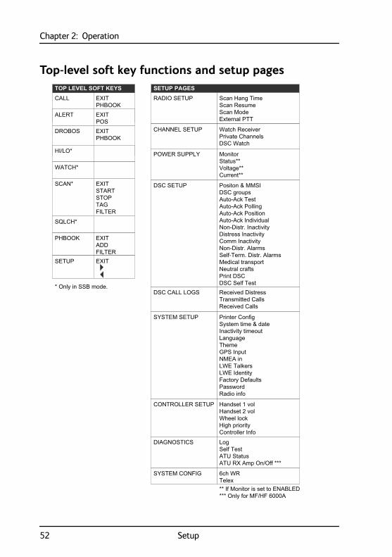
Chapter 2: Operation
Top-level soft key functions and setup pages
PHBOOK
CALL
EXITADDFILTER
EXITPHBOOK
ALERT EXITPOS
DROBOS EXITPHBOOK
SETUP EXIT
DSC SETUP
SETUP PAGES
Handset 1 volHandset 2 volWheel lockHigh priorityController Info
Positon & MMSIDSC groupsAuto-Ack TestAuto-Ack PollingAuto-Ack PositionAuto-Ack IndividualNon-Distr. InactivityDistress InactivityComm InactivityNon-Distr. AlarmsSelf-Term. Distr. AlarmsMedical transportNeutral craftsPrint DSCDSC Self Test
Printer ConfigSystem time & dateInactivity timeoutLanguageThemeGPS InputNMEA inLWE TalkersLWE IdentityFactory DefaultsPasswordRadio info
Scan Hang TimeScan ResumeScan ModeExternal PTT
DSC CALL LOGS
SYSTEM SETUP
RADIO SETUP
CONTROLLER SETUP
Received DistressTransmitted CallsReceived Calls
Watch ReceiverPrivate ChannelsDSC Watch
CHANNEL SETUP
TOP LEVEL SOFT KEYS
SQLCH*
HI/LO*
WATCH*
MonitorStatus**Voltage**Current**
POWER SUPPLY
** If Monitor is set to ENABLED*** Only for MF/HF 6000A
SCAN* EXITSTARTSTOPTAGFILTER
* Only in SSB mode.
LogSelf TestATU StatusATU RX Amp On/Off ***
DIAGNOSTICS
6ch WRTelex
SYSTEM CONFIG
52 Setup
Chapter 333333
Serv
ice
& m
aint
enan
ce
Service & maintenance 3
OverviewIn this chapter you find detailed information on:
• Contact for support
• Maintenance
• Troubleshooting
• Diagnostics
• Warranty and returning units for repair
Contact for supportContact your authorized dealer for technical service and support of the MF/HF radio. Before contacting your authorized dealer you can go through the troubleshooting guide to solve some of the most common operational problems.
Maintenance
Preventive maintenance
Maintenance of the SAILOR 6300 MF/HF DSC can be reduced to a weekly check and a maintenance check at each visit of the service staff. Inspect the radio for mechanical damages, salt deposits, corrosion and any foreign material. Due to its robust construction and ruggedness the radio has a long lifetime. Anyway it must carefully be checked at intervals not longer than 12 months - dependent on the current working conditions.
53
Chapter 3: Service & maintenance
Salt deposits
Antenna system, including Antenna Tuning Unit, whip antenna, feeder wire and especially supporting isolators should be checked regularly and kept clean to avoid flashovers and reduced output power causing poor radiation.
In case the indoor equipment has been exposed to sea water there is a risk of salt crystallization on the keyboard, knobs and cable connectors on the control unit, as well as on cable connectors on the transceiver unit, and they may become inoperable.
Clean the MF/HF radio system with fresh water.
Weekly installation check
Go through the following weekly check procedure:
1. Select a SSB channel or frequency pair, press PTT and check that tune is done successfully.
2. If a GPS is connected, check the position and time in the MF/HF display.
3. Send a DSC test call to an appropriate coast station or ship.
4. Enter Setup, Diagnostics, Self Test and start the applicable test, noting that RF-power will be present during testing. Note that output power is above 60W.
DSC self test
To run a loop back DSC self test, do as follows:
1. Press the soft key SETUP. If it is not in the display, press the soft key MORE until SETUP appears.
2. Press the arrow soft key or to advance to DSC SETUP.
3. Turn the selector knob to select DSC Self Test. Press and turn the selector knob to select RUN.The test will check the ability to encode/decode DSC signalling on RF level. The radio will automatically transmit a DSC safety test call to its own MMSI number without enabling the transmitter power amplifier. In
54 Maintenance
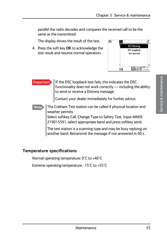
Chapter 3: Service & maintenance33333
Serv
ice
& m
aint
enan
ce
parallel the radio decodes and compares the received call to be the same as the transmitted.
The display shows the result of the test.
4. Press the soft key OK to acknowledge the test result and resume normal operation.
Temperature specifications
Normal operating temperature: 0°C to +40°C
Extreme operating temperature: -15°C to +55°C
Important If the DSC loopback test fails, this indicates the DSC functionality does not work correctly — including the ability to send or receive a Distress message.
Contact your dealer immediately for further advice.
Note The Cobham Test station can be called if physical location and weather permits. Select softkey Call. Change Type to Safety Test. Input MMSI: 219015591, select appropriate band and press softkey send.
The test station is a scanning type and may be busy replying on another band. Retransmit the message if not answered in 60 s.
OK
8381.08089.0 TXSSB
N/A
RX
DSC loopbacktest passed
DSC WarningS
Maintenance 55
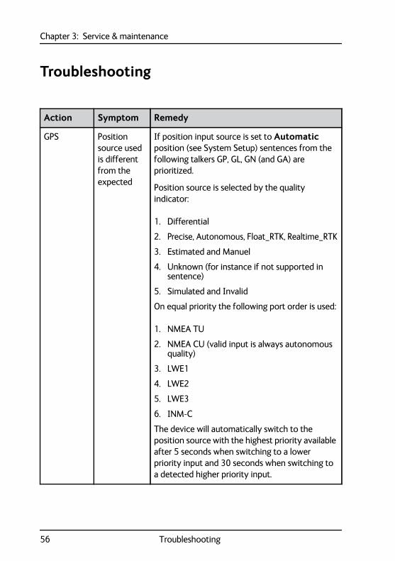
Chapter 3: Service & maintenance
Troubleshooting
Action Symptom Remedy
GPS Position source used is different from the expected
If position input source is set to Automatic position (see System Setup) sentences from the following talkers GP, GL, GN (and GA) are prioritized.
Position source is selected by the quality indicator:
1. Differential
2. Precise, Autonomous, Float_RTK, Realtime_RTK
3. Estimated and Manuel
4. Unknown (for instance if not supported in sentence)
5. Simulated and Invalid
On equal priority the following port order is used:
1. NMEA TU
2. NMEA CU (valid input is always autonomous quality)
3. LWE1
4. LWE2
5. LWE3
6. INM-C
The device will automatically switch to the position source with the highest priority available after 5 seconds when switching to a lower priority input and 30 seconds when switching to a detected higher priority input.
56 Troubleshooting
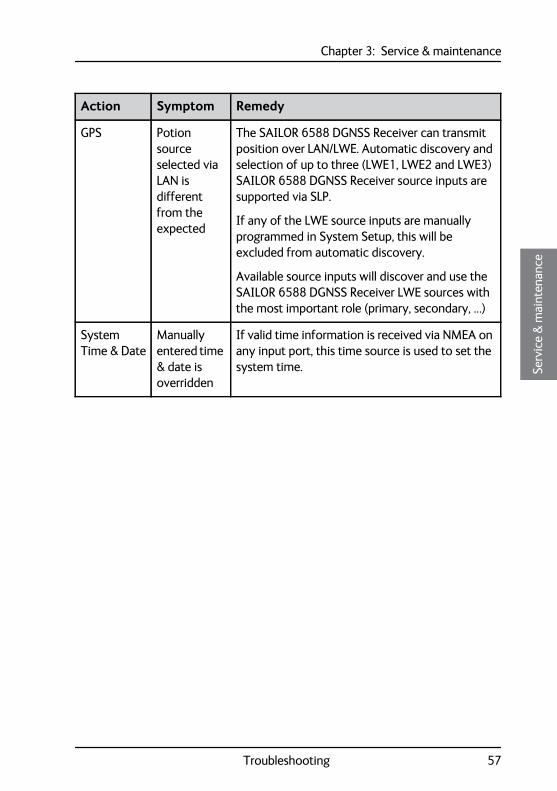
Chapter 3: Service & maintenance33333
Serv
ice
& m
aint
enan
ce
GPS Potion source selected via LAN is different from the expected
The SAILOR 6588 DGNSS Receiver can transmit position over LAN/LWE. Automatic discovery and selection of up to three (LWE1, LWE2 and LWE3) SAILOR 6588 DGNSS Receiver source inputs are supported via SLP.
If any of the LWE source inputs are manually programmed in System Setup, this will be excluded from automatic discovery.
Available source inputs will discover and use the SAILOR 6588 DGNSS Receiver LWE sources with the most important role (primary, secondary, …)
System Time & Date
Manually entered time & date is overridden
If valid time information is received via NMEA on any input port, this time source is used to set the system time.
Action Symptom Remedy
Troubleshooting 57
Chapter 3: Service & maintenance
Diagnostics
Diagnostics
In the Diagnostics menu in SETUP the following submenus are available:
• Log with system status messages
• Self Test
• ATU status
• ATU RX AMP (MF/HF system 6000A only)
Log with system status messages
In the Log menu you can view the system status, with time, date and a description (besides a technician code). The system status is not an error log. It is a log with issues logged by the radio during normal use.
Example: Bad SWR, which may occur in poor installations, hard weather making the transmitter antenna sway, etc.
To view system messages, do as follows:
1. Press the soft key SETUP. If it is not in the display, press the soft key MORE until SETUP appears.
2. Press the arrow soft key or to advance to and select Diagnostics and then Log.
3. Turn the selector knob to go to a setting, then press the selector knob to view the system setting.
4. Press EXIT to return to normal radio operation.Note If the message ATU: No Comm. appears in the display during
normal use, this might be a temporary condition depending on the current installation. If the problem persists, a pop-up message with an error message appears in the display.
58 Diagnostics
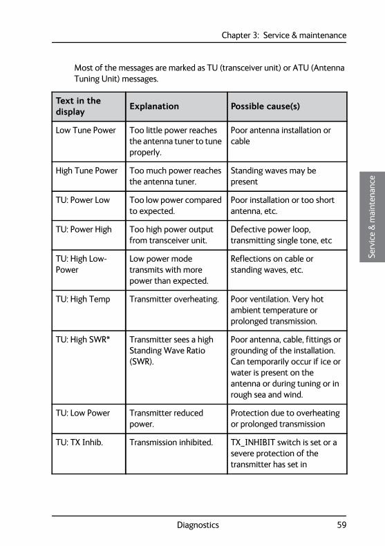
Chapter 3: Service & maintenance33333
Serv
ice
& m
aint
enan
ce
Most of the messages are marked as TU (transceiver unit) or ATU (Antenna Tuning Unit) messages.
Text in the display Explanation Possible cause(s)
Low Tune Power Too little power reaches the antenna tuner to tune properly.
Poor antenna installation or cable
High Tune Power Too much power reaches the antenna tuner.
Standing waves may be present
TU: Power Low Too low power compared to expected.
Poor installation or too short antenna, etc.
TU: Power High Too high power output from transceiver unit.
Defective power loop, transmitting single tone, etc
TU: High Low-Power
Low power mode transmits with more power than expected.
Reflections on cable or standing waves, etc.
TU: High Temp Transmitter overheating. Poor ventilation. Very hot ambient temperature or prolonged transmission.
TU: High SWR* Transmitter sees a high Standing Wave Ratio (SWR).
Poor antenna, cable, fittings or grounding of the installation. Can temporarily occur if ice or water is present on the antenna or during tuning or in rough sea and wind.
TU: Low Power Transmitter reduced power.
Protection due to overheating or prolonged transmission
TU: TX Inhib. Transmission inhibited. TX_INHIBIT switch is set or a severe protection of the transmitter has set in
Diagnostics 59
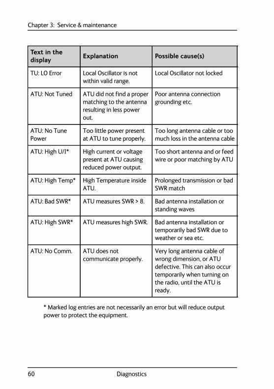
Chapter 3: Service & maintenance
* Marked log entries are not necessarily an error but will reduce output power to protect the equipment.
TU: LO Error Local Oscillator is not within valid range.
Local Oscillator not locked
ATU: Not Tuned ATU did not find a proper matching to the antenna resulting in less power out.
Poor antenna connection grounding etc.
ATU: No Tune Power
Too little power present at ATU to tune properly.
Too long antenna cable or too much loss in the antenna cable
ATU: High U/I* High current or voltage present at ATU causing reduced power output.
Too short antenna and or feed wire or poor matching by ATU
ATU: High Temp* High Temperature inside ATU.
Prolonged transmission or bad SWR match
ATU: Bad SWR* ATU measures SWR > 8. Bad antenna installation or standing waves
ATU: High SWR* ATU measures high SWR. Bad antenna installation or temporarily bad SWR due to weather or sea etc.
ATU: No Comm. ATU does not communicate properly.
Very long antenna cable of wrong dimension, or ATU defective. This can also occur temporarily when turning on the radio, until the ATU is ready.
Text in the display Explanation Possible cause(s)
60 Diagnostics
Chapter 3: Service & maintenance33333
Serv
ice
& m
aint
enan
ce
Self Test
Two different self tests are available:
• Tx single-band transmission test
• Tx multi-band transmission test
The Tx single Band test performs a tone transmitter test on the current TX frequency shown in the display.
The output of this test is the transmitted power and the battery voltage. Note that the output power is not calibrated, so the power figure may only be used as a guideline. The battery voltage should not drop significantly during this test, as this indicates a poor installation (e.g. thin wires, etc.)
The Tx Multi Band test is similar to the single band test. However, this test automatically transmits on the channel next to all six distress SSB frequencies:
• 2182+3 kHz
• 4125+3 kHz
• 6215+3 kHz
• 8291+3 kHz
• 12290+3 kHz
• 16420+3 kHz
If you exit the test before it is finished, a system status message will not be added to the diagnostics log.
ATU status
In the ATU status menu the following items are present:
• ATU software version
• ATU Selftest respons in the format 0x00. This code should be mentioned if any service inquiries regarding output power or antenna tuner are made
Note This test transmits a short test signal at full power — the radio operator needs to verify that the channel is free from any traffic before starting the test!
Diagnostics 61
Chapter 3: Service & maintenance
• ATU SWR ratio. For the tuner, the standing wave ratio of last tune session is recorded (for MF/HF system 6000B only).
• ATU TX Relays. For the tuner, the actual settings of relays in the different banks of the tuner are shown. This information can be used when making technical inquiries regarding power and tuning.
ATU RX AMP (MF/HF system 6000A only)
This can disable the RX low noise amplifier.
62 Diagnostics
Chapter 3: Service & maintenance33333
Serv
ice
& m
aint
enan
ce
Warranty and returning units for repairShould your Cobham SATCOM product fail, please contact your dealer or installer, or the nearest Cobham SATCOM partner. You will find the partner details on www.cobham.com/satcom where you also find the Cobham SATCOM Self Service Center web-portal, which may help you solve the problem.
Your dealer, installer or Cobham SATCOM partner will assist you whether the need is user training, technical support, arranging on-site repair or sending the product for repair.
Your dealer, installer or Cobham SATCOM partner will also take care of any warranty issue.
Repacking for shipment
Should you need to send the product for repair, please read the below information before packing the product.
The shipping carton has been carefully designed to protect the SAILOR 6300 MF/HF DSC and its accessories during shipment. This carton and its associated packing material should be used when repacking for shipment. Attach a tag indicating the type of service required, return address, part number and full serial number. Mark the carton FRAGILE to ensure careful handling.
If the original shipping carton is not available, the following general instructions should be used for repacking with commercially available material.
1. Wrap the defective unit in heavy paper or plastic. Attach a tag indicating the type of service required, return address, part number and full serial number.
2. Use a strong shipping container, e.g. a double walled carton.
Note Correct shipment is the customer’s own responsibility.
Warranty and returning units for repair 63
Chapter 3: Service & maintenance
3. Protect the front- and rear panel with cardboard and insert a layer of shock-absorbing material between all surfaces of the equipment and the sides of the container.
4. Seal the shipping container securely.
5. Mark the shipping container FRAGILE to ensure careful handling.
Failure to do so may invalidate the warranty.
64 Warranty and returning units for repair
GlossaryAAAAA
Glossary A
Glos
sary
AAM Amplitude Modulation
ATU Antenna Tuning Unit
DDROBOS Distress Relay On Behalf Of Someone else
DSC Digital Selective Calling
FFEC Forward Error Correction. A system of error control for data
transmission, whereby the sender adds redundant data to its messages, also known as an error-correcting code. This allows the receiver to detect and correct errors without the need to ask the sender for additional data. The advantages of forward error correction are that a back-channel is not required and retransmission of data can often be avoided.
GGMDSS Global Maritime Distress and Safety System
GPL General Public License
GPS Global Positioning System
HHF High Frequency
65
Glossary
IITU International Telecommunications Union
LLAN Local Area Network
LGPL Lesser General Public License
LWE Light Weight Ethernet
MMF Medium Frequency
MMSI Maritime Mobile Ship Identification
SSSB Single Side Band
SWR Standing Wave Ratio
TTFT Thin Film Transistor. Type of liquid crystal display.
TU Transceiver Unit
UUTC Coordinated Universal Time defined by ITU
66
IndexBBBB
Index BB
Inde
x
Aaccessories, 6acknowledgement, Distress, 25action line, display, 5activate
scan resume, 44scanning, 22watch, 21
ACTIVEactivate call, 37session, 32
ADD, 39add a contact, 39adjust
RF gain, 14speaker volume, 12
alarm panelDistress, 26
ALERT, 24AM BROADCAST, 13antenna unit
tuning, 12area calls, 38ATIS code
change, 49Auto-Ack
Individual, 45Test, 45
Bbackground sessions
DSC, 37backlight
dim, 13browse channels, 13
buttonsdescription, 4
CCALL, 39call
activate, 37Distress procedure, viDSC, 23end, 17hold, 37quick guide, 19routine, 33safety, 33update, 32urgency, 33voice, non-DSC, 33
call log, DSC, 47cancelling
Distress, 25channel
add to scan, 22information, 17remove from scan, 22select, 13
checkinstallation, 54
clearposition data, 16
color theme, 47Comm Inactivity, 46contact, 53
adding, 39deleting, 40editing, 40sorting, 38
67
Index
controls, front plate, 4cradle for 6201, installation, 6
Ddeactivate
watch, 21default reset, 49DELETE, 40delete contact, 40diagnostics, 51, 58dim, 13display, 5display color
change, 18, 47Distress, 27
acknowledgement, 25cancelling, 25power failure, 26received calls, 28relaying for someone else, 27send from alarm panel, 26sending, 23with specified parameters, 24
Distress button, 23Distress procedure, viDistress timeout, 46document number, this manual, iDROBOS, 27
68
DSC, 13background sessions, 37call log, 29, 47calls, 23loopback test, 55making a call, 29multiple calls, 37self test, 54session definition, 32setup, 45
DSC alarmsnon distress, 46
DSC messageprint, 31, 46
DSC session, 32typical display, 32
DSC soft keys, 34DSC window, 32
Eediting a contact, 40emergency calls, viend
session, 17end call, 17engagement status, 17enter position manually, 16
Ffactory defaults, 49FCC approved equipment
training information, viiifeatures, 2FILTER, 22filter
phonebook, 38
IndexBBBBB
Inde
x
frequenciessimplex, entering, 13
frequencies, entering, 13front plate, controls, 4
Ggeographical area calls, 38GPS data, 16GPS position
display, 16
Hhandset cradle
installation, 6hang time, 44HOLD
holding a call, 37session, 32
Iicons
session state, 32installation
cradle for 6201, 6handset cradle, 6
installation check, 54IP address
Control Unit, 50Transceiver Unit, 49
Kkeys on front plate, 4
knobselector, 4volume, 4
Llock
keys, 50log, 51louder, volume, 12
Mmaintenance, 53manual, document number, iMAYDAY, vimedical transport, 46menus
overview, 52soft key functions, 15
messagereplay, 42
messagesATU, 59TU, 59
MF/HF DSCdescription, 1
MMSIchange, 49
modeAM BROADCAST, 13DSC, 13select, 13SSB, 13SSB(EXT.), 13TELEX, 13
monitor power supply, 45MORE, 15
69
Index
multi-band transmission test, 61multiple calls, DSC, 37mute
speaker, 14
Nneutral crafts, 46night vision, how to dim, 13Non-dist Inactivity, 46Non-distr.alarms, 46
Ppassword, 49PHBOOK, 39phone book, 38
add contact, 39delete a contact, 40edit a contact, 40
phonebooksorting, 38
positionclear, 16enter manually, 16
position dataenter manually, 45
position Info, 45position information, 16power
off, 12on, 12
power failureDistress, 26
power supplymonitor, 45
printDSC message, 31, 46
70
printerDSC messages, 47setup, default, 31supported, 47
Printer Config, 31PTT button, 20
QQUIT, 17
Rradio call
making, 20receiving, 19
radiotelex, 41received Distress calls, 28repacking for shipment, 63repair, 63replay, 42
button, 4rewind, 42stop, 42
reset to default, 49resume time, 44returning units, 63RF exposure hazards, vRF gain, 14routine call, 33
Ssafety call, 33safety summary, ivsalt deposits, 53
IndexBBBBB
Inde
x
scanadd channel, 22hang time, 44mode, 44multi, 44remove channel, 22resume time, 44resume, activate, 44SSB voice, 15, 44start, 22
selector knob, 4, 13self test, 54, 58
multi-band, 61single band, 61
self test, DSC, 54serial number
Control Unit, 50Transceiver Unit, 49
service line, display, 5service procedure
weekly, 54session
ACTIVE, 32HOLD, 32INFO key, 36line, 33soft keys, 34state icons, 32status, 34what is, 32
setupcontroller, 50printer, 31Radio, 44system, 47watch, 44
setup pages overview, 52shipment
packing instructions, 63
simplex frequenciesenter, 13
single-band transmission test, 61soft key, 15
ADD, 39CALL, 39DELETE, 40DISACK, 28DSC, 34FILTER, 22MORE, 15PHBOOK, 39RELAY, 27STOP, 42TAG, 22WATCH, 21
soft keys, 15overview, 52
softer, volume, 12software version
Control Unit, 50Transceiver unit, 49
sorting contacts, 38speaker volume, 12specifications
temperature, operating, 55squelch
control, 4on, off, 18
SSB, 13SSB (EXT.), 13SSB voice
scan, 15, 44STOP, 42stop
replaying a message, 42watch or scan, 21, 22
71
Index
subcommunicationmode, 24telex, 24voice, 24
support, 53SW version, 49system configuration example, 8system messages, 51system overview, 3system setup, 47
TTAG, 22
remove, 22tagged channels
view, 22TELEX, 13telex, 41
subcommunication, 24temperature
operating, 55terminate
call, 17engagement, 17
testmulti-band, 61single band, 61
themecolor, change, 47
timeout, 47Distress, 46non distress, 46VHF and other non distress, 46
troubleshooting, 58tuning
antenna unit, 12TX inhibit, 20
72
Uurgency call, 33Use GPS, 16UTC time, 5
enter manually, 16
Vvariants, 3voice
call, 33subcommunication, 24
voice scan, 44volume
louder, 12softer, 12speaker, 12
Volume knob, 4
Wwarranty, iii, 63
limitation, vWATCH, 15, 21, 22watch
setup, 44start, 21stop, 21
weekly check, 54


98-131070-THR-Fwww.cobham.com/satcom
Top Related