


Languages
Pages
Legal


From code leadership and guidance to industrial labels, software and printing systems, HellermannTyton offers
comprehensive and versatile solutions for customized safety labels. Our products are designed to help meet OSHA,
ANSI, NFPA and NEC codes and standards to promote safety, minimize liability risks and reduce workplace injuries.
PROMOTE SAFETY | MINIMIZE RISK | REDUCE INJURIES
safety labels for electrical equipment & facilities management
» together we can make a difference

» HOW SAFE IS YOUR WORKPLACE?
» Safety Labels for E lectr ica l Equipment & Faci l i t ies Management
According to the U.S. Bureau of Labor Statistics (BLS), there were over 2.8 million1 workplace injury cases reported
in the U.S. private sector in 2012, and nearly 4,4002 fatal workplace injuries.
Every workplace carries potential risks for injuries. Safety audits must be conducted whenever building and installing
industrial automation equipment. In addition, electrical equipment must be identified and contain appropriate
warnings to reduce the risk of injury from electrical shock, Arc Flash and other hazards. And while no employer can
completely eliminate these risks and injuries, it is of the utmost importance and a duty that companies do all they
can to protect employees. Furthermore, workplace safety may be viewed as a financial imperative, as the associated
costs can be substantial.
» THE COSTS OF WORKER’S COMPENSATION CLAIMS
The Occupational Safety and Health Administration (OSHA) estimates the direct costs of workplace injuries and illness
to U.S. employers at over $1 billion each week.3 The total cost of injuries goes far beyond compensation and care for
the injury itself.4
DIRECT EXPENSES:
• Worker’s compensation payments and case management
• Medical expenses
INDIRECT EXPENSES:
• Legal fees
• Training replacement employees
• Regulatory investigations and fines
• Implementation of corrective measures
• Repairs to damaged equipment and property
• Lower productivity due to decreased employee morale and higher absenteeism
• Negative PR that can affect community and customer relations
OVERVIEW

» DUTY TO WARN
Many times, inadequate safety labeling is not discovered until after a workplace injury has occurred and the
Occupational Safety and Health Administration (OSHA) has been called in to do an accident investigation. At that point,
inadequate labeling has already done its damage – someone has been injured and, if revealed, the insufficient labeling
can be used to indicate a degree of company liability for the injury.
The duty to warn of workplace hazards is a shared responsibility. Often, electrical equipment and machinery will arrive
at the destination facility with safety labeling applied by the original equipment manufacturer (OEM). However, the
company installing and using the equipment may be required to apply additional labels on manufacturing and electrical
equipment, as well as safety and informational signage throughout the facility.
It is recommended that an employer or product manufacturer (such as electrical and automation equipment
manufacturers) provide a warning if any of the following apply:
• The product is dangerous without the warning.
• The degree of danger is or should be known to the equipment manufacturer and/or employer.
• The specific danger is not known or obvious to the user.
• Danger could arise during a foreseeable use (or misuse) of the product.
» LET US HELP
HellermannTyton safety labels for electrical equipment and facilities management are
designed to provide guidance and solutions for proper labeling design, placement,
durability and color requirements as outlined in the most recent codes and standards
issued by:
• National Electrical Code (NEC)
• National Fire Protection Association (NFPA)
• American National Standards Institute (ANSI)
• Occupational Safety & Health Administration (OSHA)
» HELLERMANNTYTON SAFETY LABEL SYSTEM SOLUTIONS
HellermannTyton knows complex labeling codes and standards, and offers a complete
system solution to safety labeling in equipment and electrical environments, including:
• Code compliance guidance
• Wide variety of industrial-grade labels and materials
• Advanced label creation software and printing systems
The intent of this brochure is to provide guidance and clarification of codes related to the labeling of electrical equipment, machinery and manufacturing facilities.
Due to space limitations, some codes may have be shortened or summarized. For full code listings, please refer to the published code books.
OVERVIEW
OVERVIEW

» UNDERSTANDING AND APPLY THE CODES
When designing safety labels for use on electrical equipment, machinery and within a
facility, there are application-specific codes and general codes that apply to all labels.
In general, those persons creating labels should keep in mind the following ANSI and
NEC codes for all safety labels:
ANSI Z535.4 - 2011 This standard established a national uniform system for signs that communicate safety information. This standard (American National Standard) provides guidance for manufacturers, employers, distributors, and others who have a desire to communicate safety information through product safety signs or labels.
ANSI Z535.4 - 10.1 EXPECTED LIFE Product safety signs or labels shall have a reasonable expected life with good color stability, symbol legibility, and word message legibility as described in Section 8.2. Reasonable expected life shall take into consideration whether the safety sign is permanent or temporary, the expected life of the product, and the foreseeable environmental use.
NEC 2014 The National Electrical Code (NEC 2014) defines where labels should be used and what information is required. The NEC suggests that label formats meet ANSI standards per NEC 110.21(B).
NEC 110.21(B)(1-3) FIELD APPLIED HAZARD MARKINGS Where caution, warning or danger signs or labels are required by this code, the labels shall meet the following requirements: (1) The marking shall adequately warn of the hazard using effective words and/or colors and/or symbols. (2) The label shall be permanently affixed to the equipment or wiring method and shall not be hand written. (3) The label shall be of sufficient durability to withstand the environment involved. The codes referenced in this book are taken from NEC 2014, NFPA 70E - 2012, NFPA 79 - 2012, ANSI Z535 - 2011, OSHA 1910 - 2012 and UL 508A Second Edition, December 20, 2013.
OVERVIEW
OVERVIEW

safety label basicsWhen reading through codes pertaining to safety labels, it is helpful to understand the different elements or parts of a label. The diagram below uses a CAUTION label to illustrate.
CAUTION!
UNGROUNDED DC SYSTEMOPERATING 480 VOLTS
BETWEEN CONDUCTORS
See ANSI Z535.4 – 2011 for a complete listing of definitions pertaining to safety labels.
Signal Word Panel
Safety Alert Symbol
Signal Word
BorderMessage Panel
identify the hazardOne of the first steps in creating safety labels is to assess the situation to determine the level of hazard. According to ANSI Z535.4 - 2011, the following types of situations should be considered and identified:
ANSI Z535.4 - 4.11 SAFETY ALERT SYMBOL A symbol that indicates a hazard. It is comprised of an equilateral triangle surrounding an exclamation mark. The safety alert symbol is only used on hazard alerting signs. It is not used on safety notice or safety instruction signs.
ANSI Z535.4 - 6.3 A safety alert symbol, when used with the signal word shall precede the signal word.
WARNING!
CAUTION!
DANGER!» DANGERIndicates a hazardous situation which, if not avoided, will result in death or serious injury.
» WARNINGIndicates a hazardous situation which, if not avoided, could result in death or serious injury.
» CAUTIONIndicates a hazardous situation which, if not avoided, could result in minor or moderate injury.
» NOTICEIs used to address practices not related to physical injury.
» SAFETY INSTRUCTION Signs indicate specific safety-related instructions or procedures.
Hazard Alerting Signs
Safety Notice and Safety Instructional Signs
!Safety Alert Symbol
LABEL DESIGN
LABEL DESIGN

signal word heightANSI Z535.4 - 8.2.3 Signal word letter height to be at least 50% greater than the height of the capital H in the message. In other words, signal word letter height should be at least 50% greater than the height of upper case lettering in the message panel.
}}
50% Taller
No greater than ½ height of signal word
Safety Alert Symbol
Signal Word Panel
Message Panel
DANGER!
HIGH VOLTAGE
KEEP AWAY
Signal Word
DANGER must be white letters on a red background.WARNING must be black letters on an orange background.CAUTION must be black letters on a yellow background.NOTICE must be italicized white letters on a blue background.SAFETY must be white letters on a green background.
the signal word panelOnce you have determined the hazard level, you can create the signal word panel of the safety label. ANSI and OSHA detail how fonts, colors and symbols should be used within the signal word panel.
ANSI Z535.4 - 8.1.1 Signal words shall be in sans serif letters in upper case only.
ANSI Z535.4 - 7.2 / OSHA 1910.145(d)(1-6) Detail color requirements for signal word panel (header) colors, as follows:
WARNING!
CAUTION!
DANGER!
Note: Informational labels (that do not require the safety word headers DANGER, WARNING, CAUTION, NOTICE or SAFETY) can be any color background with any color text. Examples include labels made for LEAN initiatives, bin labeling, rack labeling, general statements or instructions, or any other required signage.
PAPER ONLY
LABEL DESIGN
LABEL DESIGN

the message panelIn addition to the signal (header) panel, ANSI also sets requirements for other parts of the label, including the message panel and borders:
ANSI Z535.4 MESSAGE PANEL Message panel lettering should be a combination of upper or lower case letters. Upper case lettering may be used for short messages or emphasis of individual words. Message panel can be black characters on a white background or white characters on a black background.
BORDER A contrasting border MAY be used to achieve distinctiveness. The border can be in black or safety white, whatever provides for better contrast.
}}
50% Taller
No greater than ½ height of signal word
WARNING!TURN OFF PHOTOVOLTAIC
AC DISCONNECT PRIOR TO
WORKING INSIDE PANEL
Safety Alert Symbol
Signal Word Panel
Message Panel
Border
Signal Word
DANGER!
pictogramsGraphic safety symbols or pictograms are used to supplement written warnings. These symbols provide non-verbal communication about a possible hazard. The use of pictograms on labels is optional, but is recommended for the following reasons: • Pictograms help to explain hazards quickly, using visual recognition.• Using pictograms helps to communicate with nonreaders, and also helps communicate information universally, to people of all languages.• Pictograms can be used to visually convey the consequence of not avoiding the hazard.
ANSI Z535.4 - 4.13 SAFETY SYMBOL A graphic representation intended to convey a safety message without the use of words.
ANSI Z535.4 - ANNEX B4 Well designed safety symbols can often communicate hazard information quickly and across language and literacy barriers. Things to consider are the clarity, speed of communication, space availability, and translation and literacy issues. ANSI Z535.4 - ANNEX A1.4 The meaning of any safety symbols used on safety labels may be explained in collateral materials.
ANSI Z535.4 - 7.4 SAFETY SYMBOL PANEL The safety symbol panel shall have a safety black symbol on a safety white background. Other colors MAY be used for safety symbol emphasis, such as safety red for fire, etc. Note: If a surround shape is desired, the safety
symbol / pictogram should be placed within a yellow equilateral triangle. The yellow equilateral triangle is required on safety alert symbols
used on ISO compliant product safety labels and is covered in ANSI Z535.3.
PINCH POINT
LABEL DESIGN
LABEL DESIGN

service equipment
NEC 110.24(A) AVAILABLE FAULT CURRENT Field marking – service equipment other than dwelling
units shall be legibly marked in the field with the maximum fault current. The field marking(s) shall include
the date the fault-current calculation was performed.
NEC 230.70(B) SERVICE EQUIPMENT Each service disconnect shall be permanently marked to identify
it as a service disconnect.
NEC 230.2(E) IDENTIFICATION Where a building or structure is supplied by more than one service,
or any combination of branch circuits, feeders, and services, a permanent plaque or directory shall be
installed at each service disconnect location denoting the other services, feeders or branch circuits
supplying that building or structure, and the area served by each.
SERVICE
DISCONNECT
MAXIMUM AVAILABLE
FAULT CURRENT: 46532 AMPS
DATE:1/11/2012
SERVICE NO. 1
SERVICE NO. 2LOCATED AT NW
CORNER OF BUILDING
558-00311
Electrical infrastructure, which can start at the main service entrance and end at a control panel or a piece of industrial automation machinery, must be managed all along the path. Paths can include feeders, motor control centers (MCCs), disconnects, breaker panels, switchgear, transfer switches, inverters and all of the branch circuits.
disconnects NFPA 70E ARTICLE 205.12 Circuit and voltage identification shall be securely affixed and maintained in
updated and legible condition.
ANSI ZG3.22 VOLTAGE MARKERS Orange shall be used as the basic color for designating dangerous
parts of machines or energized equipment.
NEC 110.22(A) IDENTIFICATION OF DISCONNECTING MEANS Each disconnecting means shall be
legibly marked to indicate its purpose unless located and arranged so that the purpose is evident. The
marking shall be of sufficient durability to withstand the environment involved.
NEC 490.48(B)(2) ISOLATING EQUIPMENT Permanent legible signs shall be installed at isolating
equipment warning against operation while carrying current, unless the equipment is interlocked so that it
cannot be operated under load.
NEC 110.27(C) WARNING SIGNS Entrance to rooms and other guarded locations that contain exposed live
parts shall be marked with conspicuous warning signs forbidding unqualified persons to enter.
WARNINGTURN OFF POWER
SUPPLY TO EQUIPMENT PRIOR TO WORKING
INSIDE PANEL
!
558-00336 558-00314 558-00330
ELECTRICAL EQUIPMENT
ELECTRICAL EQUIPMENT

NEC 110.27(C) WARNING SIGNS Entrance to rooms and other guarded locations that contain exposed live parts shall be marked with conspicuous
warning signs forbidding unqualified persons to enter.
NEC 490.48(B)(2) ISOLATING EQUIPMENT Permanent legible signs shall be installed at isolating equipment warning against operation while carrying
current, unless the equipment is interlocked so that it cannot be operated under load.
Safety signs, safety symbols, or accident prevention tags shall be used where necessary to warn employees about electrical hazards which may endanger them as required by OSHA 1910.145.
558-00336 558-00311 558-00330 558-00328
ELECTRICAL EQUIPMENT
ELECTRICAL EQUIPMENT
distribution panel NFPA 70E ARTICLE 205.12 Circuit and voltage identification shall be securely affixed and maintained in updated and legible condition.
ANSI ZG3.22 VOLTAGE MARKERS Orange shall be used as the basic color for designating dangerous parts of machines or energized equipment.
NEC 110.16 ARC FLASH LABELS / NFPA 70E ARTICLE 130.5(C) EQUIPMENT LABELING Electrical equipment such as switchboards, switchgear,
panelboards, industrial control panels, meter socket enclosures, and motor control centers, that are in other than dwelling units, and are likely to
require examination, adjustment, servicing or maintenance shall be field or factory marked to warn qualified persons of potential electric arc flash.
NEC 408.4(A) CIRCUIT DIRECTORY OR CIRCUIT IDENTIFICATION Every circuit and circuit modification shall be legibly identified as to its clear,
evident, and specific purpose or use. The identification shall include an approved degree of detail that allows each circuit to be distinguished from all
others. The identification shall be included in a circuit directory that is located on the face or inside of the panel door.
NEC 210.5(C)(1)(B) POSTING OF IDENTIFICATION MEANS The method utilized for conductors originating within each branch-circuit distribution
equipment shall be documented in a manner that is readily available or shall be permanently posted at each branch-circuit panelboard or similar
branch-circuit distribution equipment.
NEC 408.3(F)(1) HIGH LEG IDENTIFICATION A switchboard, switchgear, or panelboard containing a 4-wire, delta-connected system where the
mid-point of one phase winding is grounded shall be legibly and permanently marked.
NEC 110.26(A)(1-3) SPACES ABOUT ELECTRICAL EQUIPMENT Access to working space shall be provided and maintained about all electrical
equipment to permit ready and safe operation and maintenance of such equipment. Working space shall comply with the dimensions of 110.26(A)(1),
(A)(2) and (A)(3).

switchboards and feeders NFPA 70E ARTICLE 205.12 Circuit and voltage identification shall be securely affixed and maintained in updated and legible condition.
ANSI ZG3.22 VOLTAGE MARKERS Orange shall be used as the basic color for designating dangerous parts of machines or energized equipment.
NEC 408.4(B) SOURCE OF SUPPLY All switchboards, switchgear, and panelboards supplied by a feeder(s) in other than one- or two-family
dwellings shall be marked to indicate each device or equipment where the power originates.
NEC 110.16 ARC FLASH LABELS / NFPA 70E ARTICLE 130.5(C) EQUIPMENT LABELING Electrical equipment such as switchboards, switchgear,
panelboards, industrial control panels, meter socket enclosures, and motor control centers, that are in other than dwelling units, and are likely to
require examination, adjustment, servicing or maintenance shall be field or factory marked to warn qualified persons of potential electric arc flash.
NEC 110.27(C) WARNING SIGNS Entrance to rooms and other guarded locations that contain exposed live parts shall be marked with conspicuous
warning signs forbidding unqualified persons to enter.
NEC 490.48(B)(2) ISOLATING EQUIPMENT Permanent legible signs shall be installed at isolating equipment warning against operation while carrying
current, unless the equipment is interlocked so that it cannot be operated under load.
NEC 408.4(A) CIRCUIT DIRECTORY OR CIRCUIT IDENTIFICATION Every circuit and circuit modification shall be legibly identified as to its clear,
evident, and specific purpose or use. The identification shall include an approved degree of detail that allows each circuit to be distinguished from all
others. The identification shall be included in a circuit directory that is located on the face or inside of the panel door.
NEC 705.12(D)(3) MARKING Equipment containing overcurrent devices or circuits supplying power from multiple sources shall be marked to indicate
the presence of all sources.
NEC 110.22(B) ENGINEERED SERIES COMBINATION SYSTEMS Shall be legibly marked in the field as described by the engineer to indicate the
equipment has been applied with a series combination rating. The marking shall meet the requirements in 110.21(B) and shall be readily visible.
558-00336 596-00504 558-00307558-00330 558-00328
ELECTRICAL EQUIPMENT
ELECTRICAL EQUIPMENT

industrial control panels
OSHA 1910.335(B)(1) Safety signs, safety symbols, or accident prevention tags shall be used where necessary to warn employees about electrical
hazards which may endanger them as required by 1919.145.
UL 508A SECTION 55.1 Cautionary markings shall be located on a part that is not removable without impairing the operation or appearance of
the equipment.
UL 508A SECTION 52.4 Markings required to be placed on an industrial control panel as specified in notes (a) – (d) and note (f) of Table 52.1 shall be
made by die stamping, silk-screening, or etching in metal or plastic or with an indelible ink on adhesive backed label stock and permanently attached
to the industrial control panel by rivets, screws, or adhesive.
UL 508A SECTION 52 GENERAL MARKINGS Follow all marking instructions as outlined in UL 508A second edition, dated December 30, 2013 or later.
The NEC defines industrial control panels as an assembly of two or more power circuit components, control circuit components or any combination of power and control circuit components. These may include panels designated for the control of specific equipment — such as industrial machinery. These components, with associated wiring and terminals, are mounted on, contained within, an electrical enclosure or mounted on a subpanel. The primary hazards relating to these panels concern the use of electricity.
UL 508A SECTION 55.2 A cautionary marking shall be prefixed with the word “CAUTION” or “WARNING” as applicable, in letters not less than 1/8”
(3.2mm) high. The remaining letters of such marking, unless otherwise specified, shall not be less than 1/16” (1.6mm) high.
UL 508A SECTION 55.3 A cautionary marking intended to instruct the operator shall be legible and visible to the operator during normal operation of the
equipment. A marking that provides servicing instructions shall be legible and visible when such servicing is performed.
CONTROL PANEL
CONTROL PANEL
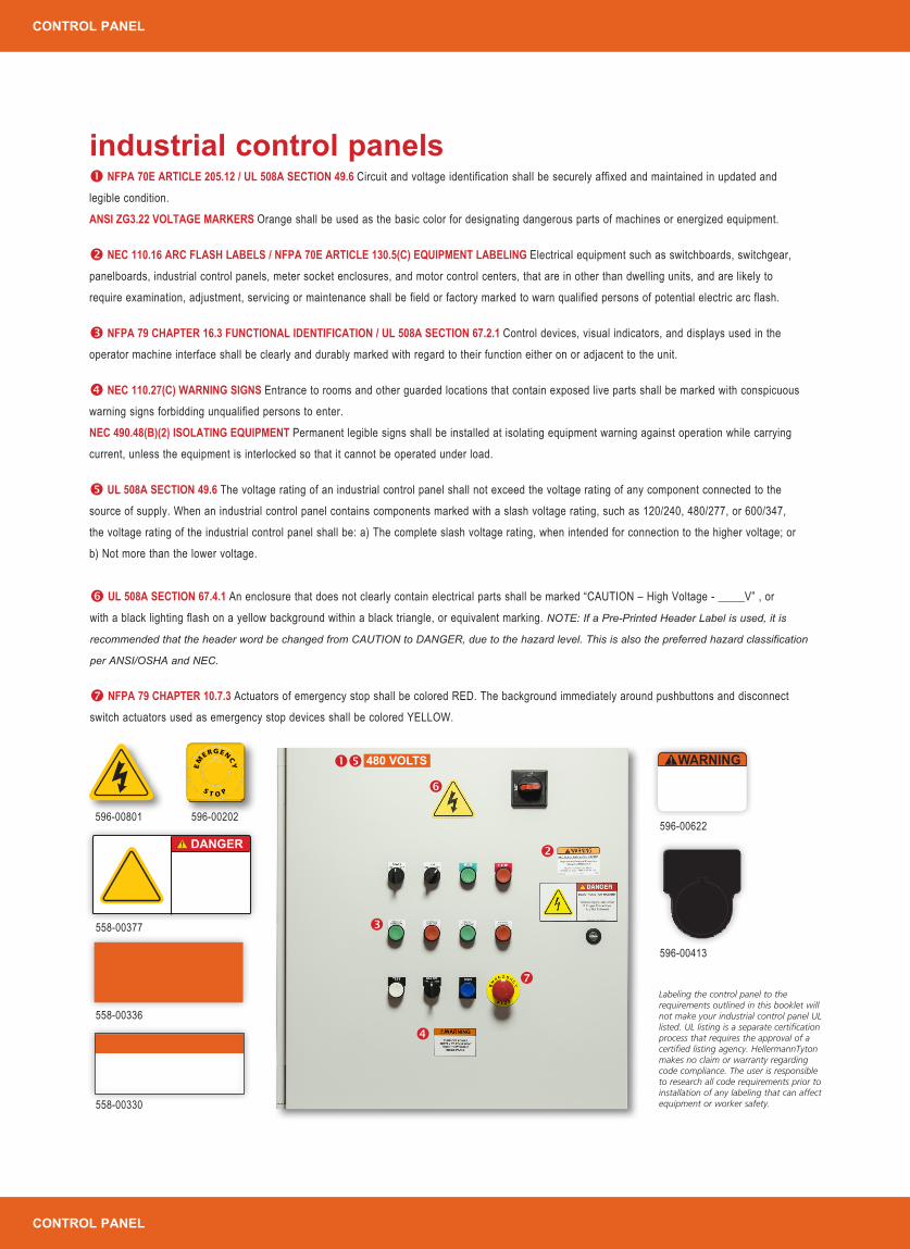
NFPA 70E ARTICLE 205.12 / UL 508A SECTION 49.6 Circuit and voltage identification shall be securely affixed and maintained in updated and
legible condition.
ANSI ZG3.22 VOLTAGE MARKERS Orange shall be used as the basic color for designating dangerous parts of machines or energized equipment.
NEC 110.16 ARC FLASH LABELS / NFPA 70E ARTICLE 130.5(C) EQUIPMENT LABELING Electrical equipment such as switchboards, switchgear,
panelboards, industrial control panels, meter socket enclosures, and motor control centers, that are in other than dwelling units, and are likely to
require examination, adjustment, servicing or maintenance shall be field or factory marked to warn qualified persons of potential electric arc flash.
NFPA 79 CHAPTER 16.3 FUNCTIONAL IDENTIFICATION / UL 508A SECTION 67.2.1 Control devices, visual indicators, and displays used in the
operator machine interface shall be clearly and durably marked with regard to their function either on or adjacent to the unit.
NEC 110.27(C) WARNING SIGNS Entrance to rooms and other guarded locations that contain exposed live parts shall be marked with conspicuous
warning signs forbidding unqualified persons to enter.
NEC 490.48(B)(2) ISOLATING EQUIPMENT Permanent legible signs shall be installed at isolating equipment warning against operation while carrying
current, unless the equipment is interlocked so that it cannot be operated under load.
UL 508A SECTION 49.6 The voltage rating of an industrial control panel shall not exceed the voltage rating of any component connected to the
source of supply. When an industrial control panel contains components marked with a slash voltage rating, such as 120/240, 480/277, or 600/347,
the voltage rating of the industrial control panel shall be: a) The complete slash voltage rating, when intended for connection to the higher voltage; or
b) Not more than the lower voltage.
industrial control panels
UL 508A SECTION 67.4.1 An enclosure that does not clearly contain electrical parts shall be marked “CAUTION – High Voltage - _____V” , or
with a black lighting flash on a yellow background within a black triangle, or equivalent marking. NOTE: If a Pre-Printed Header Label is used, it is
recommended that the header word be changed from CAUTION to DANGER, due to the hazard level. This is also the preferred hazard classification
per ANSI/OSHA and NEC.
NFPA 79 CHAPTER 10.7.3 Actuators of emergency stop shall be colored RED. The background immediately around pushbuttons and disconnect
switch actuators used as emergency stop devices shall be colored YELLOW.
480 VOLTS
Labeling the control panel to the requirements outlined in this booklet will not make your industrial control panel UL listed. UL listing is a separate certification process that requires the approval of a certified listing agency. HellermannTyton makes no claim or warranty regarding code compliance. The user is responsible to research all code requirements prior to installation of any labeling that can affect equipment or worker safety.
DANGER!
558-00336
558-00377
596-00801
WARNING!
596-00202
558-00330
596-00622
596-00413
EM
ERGENCY
S T O P
CONTROL PANEL
CONTROL PANEL

NEC 409.110 / UL 508A SECTION 52.1 ENCLOSURES An industrial control panel shall be marked with the following information that is plainly visible
after installation. 1) Manufacturer’s name or trademark or authorized designation. 2) Supply voltages, number of phases, and full load current for each
incoming supply circuit. 3) If supplied by more than one power source, the panel shall be marked to indicate more than one disconnecting means is
required to de-energize the equipment. 4) Short circuit current rating (SCCR). 5) If intended as service equipment shall be marked as such. 6) Electrical
wiring diagram or ID number of separate diagram. 7) Factory identification. 8) Enclosure type.
UL 508A SECTION 56.1 FUSE HOLDER MARKINGS A branch circuit fuse holder that accepts a fuse having a rating larger than the maximum specified
rating and all control panel circuit fuseholders shall be marked with the voltage and current rating of the replacement fuse. Note: Fuse ratings also fall
under NEC 409 for short circuit current rating (SCCR) where a panel’s overall short circuit current rating is important to passing inspection.
Customers may require evidence of compliance with 110.3(B) and listing the fuse number and type will ensure that the SCCR rating does
not change.
NEC 110.3(B) EXAMINATION, IDENTIFICATION, INSTALLATION AND USE OF EQUIPMENT The torque and fuse requirements can be labeled per NEC
110.3(B) which states that listed or labeled equipment shall be installed and used in accordance with any instructions included in the listing labeling.
NFPA 79 CHAPTER 16.5.4 All control panel devices and components shall be plainly identified with the same designation as shown on the machine
drawings or diagram(s).
NFPA 79 CHAPTER 13.1.1.10 Identification tags shall be readable, permanent, and identified for use in the physical environment.
Note on Wire Identification: Printable heat shrink tubing or self-laminating labels are industry standards for marking wires.
industrial control panels
NFPA 79 CHAPTER 13.1.1.6 Terminals on terminal blocks shall be plainly identified to correspond to markings on the diagram.
NEC 250.126(3) MARKING If the terminal for the grounding conductor is not visible, the conductor entrance hole shall be marked with the word
GREEN or GROUND, the letters G or GR, a grounding symbol, or otherwise identified with a distinctive green color.
UL 508A SECTION 54.5 Identify your grounding conductor terminal with the words “Ground” or “Grounding”, or with the letters “G”, “GR”, “GRD”,
“GND”, or “GRND”.
558-00331
TAG79T1-795, TAG72T1-795
TAG75T1-822
TAG22T3-100B
596-00380
558-00309
CONTROL PANEL
CONTROL PANEL

industrial control panels - special circumstances UL 508A SECTION 67.1.3 When the main overcurrent protection in the panel is intended to provide
protection for the supply conductors in the machine, the panel shall be marked “Supply conductor and
machine overcurrent protection provided at main supply terminals.”
UL 508A SECTION 53.4 An enclosed industrial control panel consisting of two or more sections
intended to be connected together in the field shall have the following marking, or equivalent wording,
on each section.
UL 508A SECTION 55.4 An industrial control panel intended to be provided with more than one supply
source such that more than one disconnect is required to disconnect all power within the control panel shall
be marked with the word “CAUTION” and the message panel text as shown, or equivalent.
UL 508A SECTION 55.5 The marking for an enclosure intended for field assembly of the bonding means
in accordance with 24.1(b) shall be located where visible during installation, such as inside the cover, and
consist of the word “CAUTION” and the message panel text as shown, or equivalent. CAUTION!
Bonding between conduit connection is not automatic
and must be provided as part of the installation
CAUTION!Risk of Electric Shock
More than one disconnect switch may be required
to de-energize the equipment before servicing
Supply conductor and machine overcurrent protection provided
at main supply terminals
Section 1 of 2see diagram No. 865/Afor interconnections
UL 508A SECTION 54.11(A,B,C,D) All field-wiring terminals shall be marked with one of the following:
a) “Use Copper Conductors Only” for terminals intended for connection only to copper wire.
b) “Use Aluminum Conductors Only” for terminals evaluated only for connection to aluminum wire.
c) “Use Copper or Aluminum Conductors” or “Use Copper, Copper-Clad, Aluminum, or Aluminum
Conductors” for terminals evaluated for either copper or aluminum wire.
d) “Use Copper or Copper-Clad Aluminum Conductors” for terminals evaluated for connection to either
copper or copper clad aluminum wire.
UL 508A SECTION 60.3 An industrial control panel schematic wiring diagram that includes devices that
are not provided with the industrial control panel shall be marked to indicate that these devices shall be
provided by the installer.
NEC 409.110 If the industrial control panel is intended as service equipment, it shall be marked to identify
it as being suitable for use as service equipment.
CONTROL PANEL
CONTROL PANEL

UL 508A SECTION 55.6 (A,B) An industrial control provided with an instantaneous trip circuit breaker used as branch circuit protection for a
combination motor controller shall be marked with the following:
a) With the word “WARNING” and the message panel text as shown, or equivalent.
b) With the word “WARNING” and the message panel text as shown, or equivalent.
UL 508A SECTION 55.7 (A,B) An industrial control with a self-protected combination motor controller shall be marked with the following:
a) With the word “WARNING” and the message panel text as shown, or equivalent.
b) With the word “WARNING” and the message panel text as shown, or equivalent.
a)
a)
b)
b)
WARNING
WARNING
WARNING
WARNING
!
!
!
!
To maintain overcurrent, short circuit, and ground-fault protection, the manufacturer’s
instructions for selectingcurrent elements and settingthe instantaneous-trip circuitbreaker must be followed.
To maintain overcurrent short-circuit, and ground fault protection, the
manufacturer’s instructions for selection of overload and short circuit protection
must be followed to reduce the risk of fire or electrical shock.
Tripping of the instantaneous-tripcircuit breaker is an indication that a fault current has been interrupted.
Current-carrying components of the magneticmotor controller should be examined andreplaced if damaged to reduce the risk of
fire or electric shock. If burnout of thecurrent element of an overload relay occurs,
the complete overload relay mustbe replaced.
If an overload or a fault current interruption occurs, circuits must be
checked to determine the cause of the interruption. If a fault condition exits,
the current-carrying components should be examined and replaced if damaged,
and the integral current sensors must be replaced to reduce the risk of fire
or electric shock.
industrial control panels - special circumstances
industrial automationMany pieces of industrial automation machinery include an industrial control panel. Refer to the industrial control panel’s instruction manual for labeling requirements.UL 508A SECTION 55.1 Cautionary markings shall be located on a part that is not
removable without impairing the operation or appearance of the equipment.
DANGER! DANGER!
596-00204 596-00371
596-00377 596-00389
CONTROL PANEL
INDUSTRIAL AUTOMATION

PRODUCT REFERENCE
industrial automationAs the use of industrial automation increases, so do the risks of associated injuries. The equipment used in automated environments is complex and can be dangerous if not used properly. It is important that employers clearly communicate hazards and operational directives to industrial automation workers.
UL 508A SECTION 55.2 A cautionary marking shall be prefixed with the word “CAUTION” or “WARNING” as applicable, in letters not less than 1/8”
(3.2mm) high. The remaining letters of such marking, unless otherwise specified, shall not be less than 1/16” (1.6mm) high.
UL 508A SECTION 55.3 A cautionary marking intended to instruct the operator shall be legible and visible to the operator during normal operation of the
equipment. A marking that provides servicing instructions shall be legible and visible when such servicing is performed.
OSHA 1910.303(E) Electrical equipment may not be used unless the following markings have been placed on the equipment. The manufacturer’s name
and trademark, other marking giving voltage, current, wattage or other ratings as necessary.
OSHA 1910.335(B)(1) Safety signs, safety symbols, or accident prevention tags shall be used where necessary to warn employees about electrical
hazards which may endanger them as required by 1919.145.
OSHA 1910.145 Signal word must be readable from a distance of 5 feet (1.52m). Signs must not constitute a hazard in themselves (sharp corners, etc).
Signs must be affixed as close as possible to the hazard via adhesive, string, or wire to prevent unintentional removal. The major message shall be
presented in either pictographs, text or both.
OSHA 1910.145(E)(2) The wording of any sign should be easily read and concise. The sign should contain sufficient information to be easily understood.
The wording should make a positive, rather than negative suggestion and should be accurate in fact.
The initial labeling is only one part of proper industrial safety communication and training. To help maximize workplace safety, labels should be inspected periodically for wear and compliance to the most recent codes and standards.
» ANSI Z535.4 10.2.1 Product safety signs or labels should be periodically inspected and cleaned by the product user as necessary to maintain good legibility as described in section 8.2.
» ANSI Z535.4 10.2.2 Product safety signs or labels should be replaced by the product user when they no longer meet the legibility requirements as described in Section 8.2. In cases where products have an extensive expected life or where exposed to extreme conditions, the product user should contact either the product manufacturer or another source to determine means for obtaining replacement signs or labels.
label maintenance and replacement
WARNING!
PLACE MACHINE
IN JOG BEFORE
OPENING GUARD
INDUSTRIAL AUTOMATION

558-00336 l 1” wide roll558-00337 l 2” wide roll558-00338 l 3” wide roll
558-00339 l 1” wide roll558-00341 l 2” wide roll558-00343 l 3” wide roll
558-00310 l 1” wide roll558-00314 l 2” wide roll558-00346 l 3” wide roll
558-00307 l 1” wide roll558-00311 l 2” wide roll558-00374 l 3” wide roll
558-00340 l 1” wide roll558-00342 l 2” wide roll558-00344 l 3” wide roll558-00351 l 4” wide roll
558-00309 l 1” wide roll558-00313 l 2” wide roll558-00345 l 3” wide roll558-00350 l 4” wide roll
558-00308 l 1” wide roll558-00312 l 2” wide roll558-00006 l 3” wide roll558-00370 l 4” wide roll
558-00327 l 2” wide roll558-00330 l 3” wide roll558-00333 l 4” wide roll
558-00328 l 2” wide roll558-00331 l 3” wide roll558-00334 l 4” wide roll
SOLID COLORED CONTINUOUS VINYL ROLLS PRE-PRINTED CONTINUOUS
COLORED SIGNAL PANEL LABELS
HellermannTyton industrial safety labelsWe offer a wide variety of labels designed to meet industrial safety labeling needs.
PLASTIC NAMEPLATES
PRODUCT REFERENCE
PRE-PRINTED SIGNAL WORD LABELS FOAM NAMEPLATE LABELS
WARNING
WARNING
!
DANGER
DANGER
596-00379 l 1.35” x 2.75”596-00377 l 2.75” x 5.5”
596-00387 l 1.35” x 2.75”596-00389 l 2.75” x 5.5”
596-00378 l 1.35” x 2.75”596-00376 l 2.75” x 5.5”
596-00386 l 1.35” x 2.75”596-00388 l 2.75” x 5.5”
596-00203 l 4” x 6”596-00424 l 3” x 2”
596-00204 l 4” x 6”596-00426 l 3” x 2”
596-00621 l 4” x 6”596-00622 l 3” x 2”
596-00427 l 4” x 6”596-00425 l 3” x 2”
596-00371 l 4” x 6”596-00372 l 3” x 2”
WARNING! CAUTION!DANGER!
!
! !
596-00414 l 1.75” x 1.75”
596-00417 l 3” x 4”
596-00504 l 2” x 1”596-00507 l 2” x 1”
596-005031.06” x .49”
596-005001.06” x .49”
596-004121.25” x 1.25”
UNLOCK.88” Hole Dia. – 596-00413
596-00415 l 1.75” x 1.75” 596-004131.25” x 1.25”
PRODUCT REFERENCE

Cont inuous Rol l s
Continuous Vinyl Rolls come in a wide variety of colors and widths for creating customized labels on demand. Choose from blank, solid-color and color banded labels. Solid labels are used for marking voltage, disconnecting means, electrical panels, conduit, busways, switches, circuit breakers and other electrical equipment. Banded labels have orange and yellow color bands on the top for creating Caution and Warning signal word labels, on demand. Best for use with a thermal transfer printer that has an integrated cutter like HellermannTyton’s TT230SMC or TTM430 with cutter.
Article No. Part No. Type
Width Length
Color
Pkg. Qty.
Pkg.Typein (mm) ft (m) ft
Solid Colored
558-00309 558-00309 HT1WH250 1.0 (25.4) 250.0 (76.2) White 250 Roll
558-00313 558-00313 HT2WH250 2.0 (50.8) 250.0 (76.2) White 250 Roll
558-00345 558-00345 HT3WH250 3.0 (76.2) 250.0 (76.2) White 250 Roll
558-00350 558-00350 HT4WH250 4.0 (101.6) 250.0 (76.2) White 250 Roll
558-00310 558-00310 HT1YE250 1.0 (25.4) 250.0 (76.2) Yellow 250 Roll
558-00314 558-00314 HT2YE250 2.0 (50.8) 250.0 (76.2) Yellow 250 Roll
558-00346 558-00346 HT3YE250 3.0 (76.2) 250.0 (76.2) Yellow 250 Roll
558-00308 558-00308 HT1RD250 1.0 (25.4) 250.0 (76.2) Red 250 Roll
558-00312 558-00312 HT2RD250 2.0 (50.8) 250.0 (76.2) Red 250 Roll
558-00006 558-00006 HT3RD250 3.0 (76.2) 250.0 (76.2) Red 250 Roll
558-00370 558-00370 HT4RD250 4.0 (101.6) 250.0 (76.2) Red 250 Roll
558-00307 558-00307 HT1BK250 1.0 (25.4) 250.0 (76.2) Black 250 Roll
558-00311 558-00311 HT2BK250 2.0 (50.8) 250.0 (76.2) Black 250 Roll
558-00374 558-00374 HT3BK250 3.0 (76.2) 250.0 (76.2) Black 250 Roll
558-00336 558-00336 HT1OE250 1.0 (25.4) 250.0 (76.2) Orange 250 Roll
Product Selection
558-00337 558-00337 HT2OE250 2.0 (50.8) 250.0 (76.2) Orange 250 Roll
558-00338 558-00338 HT3OE250 3.0 (76.2) 250.0 (76.2) Orange 250 Roll
558-00339 558-00339 HT1BU250 1.0 (25.4) 250.0 (76.2) Blue 250 Roll
558-00341 558-00341 HT2BU250 2.0 (50.8) 250.0 (76.2) Blue 250 Roll
558-00343 558-00343 HT3BU250 3.0 (76.2) 250.0 (76.2) Blue 250 Roll
558-00340 558-00340 HT1GN250 1.0 (25.4) 250.0 (76.2) Green 250 Roll
558-00342 558-00342 HT2GN250 2.0 (50.8) 250.0 (76.2) Green 250 Roll
558-00344 558-00344 HT3GN250 3.0 (76.2) 250.0 (76.2) Green 250 Roll
558-00351 558-00351 HT4GN250 4.0 (101.6) 250.0 (76.2) Green 250 Roll
Banded Colored
558-00327 558-00327 HT2OE50250 2.0 (50.8) 250.0 (76.2) Orange 250 Roll
558-00328 558-00328 HT2YE50250 2.0 (50.8) 250.0 (76.2) Yellow 250 Roll
558-00330 558-00330 HT3OE75250 3.0 (76.2) 250.0 (76.2) Orange 250 Roll
558-00331 558-00331 HT3YE75250 3.0 (76.2) 250.0 (76.2) Yellow 250 Roll
558-00333 558-00333 HT4OE10250 4.0 (101.6) 250.0 (76.2) Orange 250 Roll
558-00334 558-00334 HT4YE10250 4.0 (101.6) 250.0 (76.2) Yellow 250 Roll
Dimensions are approximate and subject to technical changes. Use Part No. for ordering and Type for specification purposes. Not all items in stock. Contact HellermannTyton for stock status before ordering.
Material Number 1500
Material Vinyl
Operating Temperatures-40°F to +180°F (-40°C to +82°C)
Adhesive Acrylic
Material Data
Material Number 336/926
Material Polyester (PET)
Operating Temperatures-40°F to +302°F (-40°C to +150°C)
Adhesive Acrylic
Material Data
Solid Colored Banded Colored
PRODUCT REFERENCE
PRODUCT REFERENCE

PRODUCT REFERENCE
PRODUCT REFERENCE
Pre-Pr inted Header Labels
For commonly-used safety labels, HellermannTyton offers a line of partially pre-printed signal word labels on rolls. These labels come with pre-printed Danger, Warning, Caution, Notice or Safety headers on the appropriate color background – eliminating the need print in multiple colors. Labels include a blank area for a customized message. Choose from a variety of formats, including options that allow space for printing icons, graphics and pictograms. Use with HellermannTyton’s TagPrint® Pro label design software, which includes a wide range of pictograms and icons.
Article No. Part No. Type Description
Width Length
ColorPkg. Qty.
Pkg.Typein (mm) in (mm)
596-00203 596-00203 4X6DANGER DANGER 4.00 (101.60) 6.00 (152.40) Red 250 Roll
596-00424 596-00424 3X2DANGER DANGER 3.00 (76.20) 2.00 (50.80) Red 250 Roll
596-00621 596-00621 4X6WARNING WARNING 4.00 (101.60) 6.00 (152.40) Orange 250 Roll
596-00622 596-00622 3X2WARNING WARNING 3.00 (76.20) 2.00 (50.80) Orange 250 Roll
596-00204 596-00204 4X6NOTICE NOTICE 4.00 (101.60) 6.00 (152.40) Blue 250 Roll
596-00426 596-00426 3X2NOTICE NOTICE 3.00 (76.20) 2.00 (50.80) Blue 250 Roll
596-00427 596-00427 4X6CAUTION CAUTION 4.00 (101.60) 6.00 (152.40) Yellow 250 Roll
596-00425 596-00425 3X2CAUTION CAUTION 3.00 (76.20) 2.00 (50.80) Yellow 250 Roll
596-00371 596-00371 4X6SAFETY SAFETY 4.00 (101.60) 6.00 (152.40) Green 250 Roll
596-00372 596-00372 3X2SAFETY SAFETY 3.00 (76.20) 2.00 (50.80) Green 250 Roll
596-00378 596-00378 WV275X135 WARNING, Blank Yellow Triangle 1.35 (34.29) 2.75 (69.85) Orange 250 Roll
596-00379 596-00379 DV275X135 DANGER, Blank Yellow Triangle 1.35 (34.29) 2.75 (69.85) Red 250 Roll
596-00376 596-00376 WV55X275 WARNING, Blank Yellow Triangle 2.75 (69.80) 5.50 (139.70) Orange 250 Roll
596-00377 596-00377 DV55X275 DANGER, Blank Yellow Triangle 2.75 (69.85) 5.50 (139.70) Red 250 Roll
596-00386 596-00386 WS275X135 WARNING, Blank Symbol Panel 1.35 (34.29) 2.75 (69.85) Orange 250 Roll
Product Selection
596-00387 596-00387 DS275X135 DANGER, Blank Symbol Panel 1.35 (34.29) 2.75 (69.85) Red 250 Roll
596-00388 596-00388 WS55X275 WARNING, Blank Symbol Panel 2.75 (69.85) 5.50 (139.70) Orange 250 Roll
596-00389 596-00389 DS55X275 DANGER, Blank Symbol Panel 2.75 (69.85) 5.50 (139.70) Red 250 Roll
Hazard Labels
596-00800 596-00800 HL2X2YE HAZARD Symbol 2.0 (50.8) 2.0 (50.8) Yellow 50 Roll
596-00801 596-00801 HL3X3YE HAZARD Symbol 3.0 (76.2) 3.0 (76.2) Yellow 50 Roll
Dimensions are approximate and subject to technical changes. Use Part No. for ordering and Type for specification purposes. Not all items in stock. Contact HellermannTyton for stock status before ordering.
Material Number 336/926
Material Polyester (PET)
Operating Temperatures-40°F to +302°F (-40°C to +150°C)
Adhesive Acrylic
Material Data

PRODUCT REFERENCE
PRODUCT REFERENCE
Foam Nameplates
Foam nameplate labels are designed to replace engraved phenolic plates commonly found on control panels in many markets. Labels have a foam base so that they conform to textured surfaces, but still provide a flat printing surface. The material is resistant to chemicals, solvents, heat and UV exposure. HellermannTyton’s foam nameplate labels include printable button labels. For use with TagPrint Pro labeling software and HellermannTyton thermal transfer printers.
Article No. Part No. Type Description
Width LengthMounting
Hole Ø
ColorPkg. Qty.
Pkg.Typein (mm) in (mm) in (mm)
Colored Foam Button Nameplate Labels
596-00405 596-00405 NPLH31X38YE22.5 Nameplate With Button Hole 1.2 (30.5) 1.5 (38.1) 0.88 (22.35) Yellow 250 Roll
596-00406 596-00406 NPLH31X38RD22.5 Nameplate With Button Hole 1.2 (30.5) 1.5 (38.1) 0.88 (22.35) Red 250 Roll
596-00407 596-00407 NPLH31X38BK22.5 Nameplate With Button Hole 1.2 (30.5) 1.5 (38.1) 0.88 (22.35) Black 250 Roll
596-00404 596-00404 NPLH31X38WH22.5 Nameplate With Button Hole 1.2 (30.5) 1.5 (38.1) 0.88 (22.35) White 250 Roll
596-00323 596-00323 NPLH31X38GN22.5 Nameplate With Button Hole 1.2 (30.5) 1.5 (38.1) 0.88 (22.35) Green 250 Roll
Shaped Foam Button Nameplate Labels
596-00412 596-00412 NPLH31X31WH22.5 Nameplate With Button Hole 1.25 (31.7) 1.25 (31.7) 0.88 (22.35) White 250 Roll
596-00413 596-00413 NPLH31X31BK22.5 Nameplate With Button Hole 1.25 (31.7) 1.25 (31.7) 0.88 (22.35) Black 250 Roll
596-00414 596-00414 NPLH44X44WH30.5 Nameplate With Button Hole 1.75 (44.4) 1.75 (44.4) 1.20 (30.48) White 250 Roll
596-00415 596-00415 NPLH44X44BK30.5 Nameplate With Button Hole 1.75 (44.4) 1.75 (44.4) 1.20 (30.48) Black 250 Roll
Emergency Stop Foam Nameplate Label
596-00202 596-00202 NPL60X60YEFoam Nameplate With Emergency Stop Label
2.375 (60.3) 2.375 (60.3) 1.2 (30.48) Yellow 100 Roll
Product Selection
Material Number 518
Material Polyester (PET)
Operating Temperatures-40°F to +176°F (-40°C to + 80°C)
Adhesive Acrylic
Material Data
Foam Nameplates
596-00500 596-00500 NPL27X13WH Rectangular Nameplate 1.06 (27.0) 0.49 (12.4) - White 500 Roll
596-00503 596-00503 NPL27X13BK Rectangular Nameplate 1.06 (27.0) 0.49 (12.4) - Black 500 Roll
596-00504 596-00504 NPL51X25WH Rectangular Nameplate 2.00 (50.8) 1.00 (25.4) - White 500 Roll
596-00507 596-00507 NPL51X25BK Rectangular Nameplate 2.00 (50.8) 1.00 (25.4) - Black 500 Roll
596-00417 596-00417 NPLH76X101WH Rectangular Nameplate 3.00 (76.2) 4.00 (101.6) - White 150 Roll
Dimensions are approximate and subject to technical changes. Use Part No. for ordering and Type for specification purposes. Not all items in stock. Contact HellermannTyton for stock status before ordering.

PRODUCT REFERENCE
PRODUCT REFERENCE
Thermal Transfer Labels
HellermannTyton offers a complete line of thermal transfer printable labels for marking electrical equipment. Use metalized labels as rating plates or short circuit current rating (SCCR) labels on control panels and industrial automation equipment. Terminal block labels are provided in several common widths for use on a wide variety of standard terminal blocks. Pre-formatted phase labels come in strips of three labels, separated by a micro-perforation so that all three labels can be placed on a switchboard or panel as one piece or broken into individual pieces at the perforation for marking individual fuses or breakers.
Article No. Part No. Type
Width Length Labels per Row Color
Pkg. Qty.
Pkg.Typein (mm) in (mm)
Thermal Transfer Labels - Silver
596-80795 TAG80T1-795 TAG80T1 3.00 (76.20) 5.00 (127.00) 1 Silver 500 Roll
596-79795 TAG79T1-795 TAG79T1 4.00 (101.60) 2.00 (50.80) 1 Silver 500 Roll
596-78795 TAG78T1-795 TAG78T1 3.00 (76.20) 4.00 (101.60) 1 Silver 500 Roll
596-72795 TAG72T1-795 TAG72T1 2.75 (69.85) 1.25 (31.75) 1 Silver 3000 Roll
596-73795 TAG73T1-795 TAG73T1 2.00 (50.80) 1.00 (25.40) 1 Silver 3000 Roll
596-76795 TAG76T1-795 TAG76T1 2.50 (63.50) 2.00 (50.80) 1 Silver 1000 Roll
596-27795 TAG27T1-795 TAG27T1 1.50 (38.11) 0.75 (19.05) 1 Silver 3000 Roll
596-75795 TAG75T1-795 TAG75T1 2.00 (50.80) 0.625 (15.87) 1 Silver 2000 Roll
596-15795 TAG15T3-795 TAG15T3 1.00 (25.40) 0.50 (12.70) 3 Silver 10000 Roll
Thermal Transfer Labels - White
596-73833 596-73833 PCP2X1 2.0 (50.8) 1.0 (25.4) 1 White 3000 Roll
596-73834 596-73834 PCP3X1 3.0 (76.2) 1.0 (25.4) 1 White 3000 Roll
596-73835 596-73835 PCP4X3 4.0 (101.6) 3.0 (76.2) 1 White 1000 Roll
Phase Labels
596-00382 596-00382 PLW3P 1.0 (25.4) 0.5 (12.7) 3 White 2500 Roll
596-00383 596-00383 PLB3P 1.0 (25.4) 0.5 (12.7) 3 Black 2500 Roll
Product Selection
Article No. Part No. Type
Width Length Labels per Row Color
Pkg. Qty.
Pkg.Typein (mm) in (mm) ft
Terminal Block Continuous Rolls
596-00380 596-00380 TBL375 0.375 (9.52) 100.0 (30.48) 1 White 100 Roll
596-00381 596-00381 TBL500 0.50 (12.70) 100.0 (30.48) 1 White 100 Roll
Dimensions are approximate and subject to technical changes. Use Part No. for ordering and Type for specification purposes. Not all items in stock. Contact HellermannTyton for stock status before ordering.
Product Selection
Material Number 395
Material Polyethylene (PE)
Operating Temperatures-40°F to +176°F (-40°C to + 80°C)
Adhesive Rubber
Material Data
Terminal Block Continuous Rolls
Material Number 795
Material Type 795, Polyester, Silver Matt (SR)
Operating Temperatures-40°F to +300°F (-40°C to + 149°C)
Adhesive Acrylic
Material Data
Thermal Transfer Labels - Silver
Material Number 840W
Material Type 840, Polyester, White (WH)
Operating Temperatures-40°F to +300°F (-40°C to + 149°C)
Adhesive High Bond Acrylic
Material Data
Thermal Transfer Labels - White
Material Number 336
Material Polyester (PET)
Operating Temperatures-40°F to +300 °F (-40 °C to + 149 °C)
Adhesive Acrylic
Material Data
Phase Labels

PRODUCT REFERENCE
PRODUCT REFERENCE
Shr inkTrak
HellermannTyton’s ShrinkTrak heat shrinkable labels make it easy to mark wire, cable and other components. This military approved heat shrink tubing is flattened and assembled in a ladder-style carrier system for easy printing using a thermal transfer printer. The ladder system creates a kit of markers that can be sorted, removed and applied in any order, saving time, labor and speeding production.
Article No. Part No. Type
Width Length
Center Split ColorPkg. Qty.
Pkg.Typein (mm) in (mm)
0.125” (3.14mm) Outside Diameter
553-50002 553-50002 HST3-1WH 1.90 (48.3) 0.235 (5.97) - White 250 Roll
553-50004 553-50004 HST3-1WH-S 0.95 (24.0) 0.235 (5.97) Single White 500 Roll
553-50005 553-50005 HST3-1YE 1.90 (48.3) 0.235 (5.97) - Yellow 250 Roll
553-50007 553-50007 HST3-1YE-S 0.95 (24.0) 0.235 (5.97) Single Yellow 500 Roll
0.187" (4.74mm) Outside Diameter
553-50009 553-50009 HST4.8-1.6WH 1.90 (48.3) 0.312 (7.9) - White 250 Roll
553-50011 553-50011 HST4.8-1.6WH-S 0.95 (24.0) 0.312 (7.9) Single White 500 Roll
553-50012 553-50012 HST4.8-1.6YE 1.90 (48.3) 0.312 (7.9) - Yellow 250 Roll
553-50014 553-50014 HST4.8-1.6YE-S 0.95 (24.0) 0.312 (7.9) Single Yellow 500 Roll
0.250” (6.35mm) Outside Diameter
553-50016 553-50016 HST6-2WH 1.90 (48.3) 0.42 (10.67) - White 250 Roll
553-50019 553-50019 HST6-2WH-S 0.95 (24.0) 0.42 (10.67) Single White 500 Roll
553-50020 553-50020 HST6-2YE 1.90 (48.3) 0.42 (10.67) - Yellow 250 Roll
553-50022 553-50022 HST6-2YE-S 0.95 (24.0) 0.42 (10.67) Single Yellow 500 Roll
0.375” (9.52mm) Outside Diameter
553-50024 553-50024 HST9-3WH 1.90 (48.3) 0.597 (15.16) - White 250 Roll
553-50025 553-50025 HST9-3WH-S 0.95 (24.0) 0.597 (15.16) Single White 500 Roll
553-50026 553-50026 HST9-3YE 1.90 (48.3) 0.597 (15.16) - Yellow 250 Roll
553-50027 553-50027 HST9-3YE-S 0.95 (24.0) 0.597 (15.16) Single Yellow 500 Roll
Product Selection
0.500” (12.70mm) Outside Diameter
553-50029 553-50029 HST12-4WH 1.90 (48.3) 0.77 (19.55) - White 250 Roll
553-50030 553-50030 HST12-4WH-S 0.95 (24.0) 0.77 (19.55) Single White 500 Roll
553-50031 553-50031 HST12-4YE 1.90 (48.3) 0.77 (19.55) - Yellow 250 Roll
553-50032 553-50032 HST12-4YE-S 0.95 (24.0) 0.77 (19.55) Single Yellow 500 Roll
0.750” (19.00mm) Outside Diameter
553-50034 553-50034 HST18-6WH 1.90 (48.3) 1.2 (30.48) - White 250 Roll
553-50035 553-50035 HST18-6WH-S 0.95 (24.0) 1.2 (30.48) Single White 500 Roll
553-50036 553-50036 HST18-6YE 1.90 (48.3) 1.2 (30.48) - Yellow 250 Roll
553-50037 553-50037 HST18-6YE-S 0.95 (24.0) 1.2 (30.48) Single Yellow 500 Roll
1.000” (25.40mm) Outside Diameter
553-50039 553-50039 HST24-8WH 1.90 (48.3) 1.69 (42.93) - White 250 Roll
553-50040 553-50040 HST24-8WH-S 0.95 (24.0) 1.69 (42.93) Single White 500 Roll
553-50041 553-50041 HST24-8YE 1.90 (48.3) 1.69 (42.93) - Yellow 250 Roll
553-50042 553-50042 HST24-8YE-S 0.95 (24.0) 1.69 (42.93) Single Yellow 500 Roll
1.500” (38.10mm) Outside Diameter
553-50209 553-50209 HST39-13WH 1.90 (48.30) 2.26 (57.4) - White 150 Roll
553-50226 553-50226 HFST39-13WH-S 0.95 (24.13) 2.26 (57.4) Single White 300 Roll
553-50225 553-50225 HFST39-13YE 1.90 (48.30) 2.26 (57.4) - Yellow 150 Roll
553-50227 553-50227 HFST39-13YE-S 0.95 (24.13) 2.26 (57.4) Single Yellow 300 Roll
Dimensions are approximate and subject to technical changes. Use Part No. for ordering and Type for specification purposes. Not all items in stock. Contact HellermannTyton for stock status before ordering.
Material Polyolefin, Cross-linked (PO-X)
Operating Temperatures-67°F to +275°F (-55°C to +135°C)
Flammability UL224 VW-1
Material Data

PRODUCT REFERENCE
PRODUCT REFERENCE
Plast i c Nameplates
HellermannTyton plastic nameplates are made of polycarbonate that is rated to UL94VO for flame retardancy. Plastic nameplates can be mechanically mounted, and include a clear polycarbonate cover that protects the printed text. Designed for longterm durability, plastic nameplates still allow individual customization, on demand. Available in classic nameplate and button designs, they are excellent for use on industrial automation equipment, industrial control panels as well as electrical boxes, push button stations or anything that requires longterm identification.
Article No. Part No. Type Description
Width HeightMounting
Hole Ø
ColorPkg. Qty.
Pkg.Typein (mm) in (mm) in (mm)
Plastic Button Nameplate Bases
596-00189 596-00189 PTSA-22 Plastic Button Base, With Locators 1.12 (28.0) 1.87 (47.0) 0.88 (22.35) Black 100 Pack
596-00190 596-00190 PTOA-22 Plastic Button Base, Without Locators 1.12 (28.0) 1.87 (47.0) 0.88 (22.35) Black 100 Pack
White Inserts
596-00418 596-00418 WPL15X27Insert For 596-00189, 596-00190, 596-00191
1.06 (27.0) 0.59 (15.0) - White 360 Pack
596-00419 596-00419 WPL15X49 Insert For 596-00192 1.92 (49.0) 0.59 (15.0) - White 180 Pack
596-00420 596-00420 WPL15X67 Insert For 596-00193 2.63 (67.0) 0.59 (15.0) - White 90 Pack
Labels For Use On Inserts
596-00184 596-00184 NPL25X13 For Use On White Insert 596-00418 1.00 (25.4) 0.5 (12.7) - White 500 Roll
596-00185 596-00185 NPL47X13 For Use On White Insert 596-00419 1.85 (46.9) 0.5 (12.7) - White 500 Roll
596-00183 596-00183 NPL63X13 For Use On White Insert 596-00420 2.50 (63.5) 0.5 (12.7) - White 500 Roll
Clear (Transparent) Covers
596-00194 596-00194 TC15X27Insert For 596-00189, 596-00190, 596-00191
1.06 (27.0) 0.59 (15.0) - Transparent 360 Pack
596-00195 596-00195 TC15X49 Insert For 596-00192 1.92 (49.0) 0.59 (15.0) - Transparent 180 Pack
596-00196 596-00196 TC15X67 Insert For 596-00193 2.63 (67.0) 0.59 (15.0) - Transparent 90 Pack
Product Selection
TagPr int Pro ®
TagPrint Pro 3.0 is a revolution in simplicity, in design and ease of use. The advanced feature set is easy to navigate, and comes with a wide range of pre-saved label designs for the most common Danger, Warning, Caution, Notice and other labels required by codes and standards. Simply select the label type you required, open the file and you can add text, make simple edits and changes and then print to any thermal transfer printer. TagPrint Pro makes it easy to meet required NEC, NFPA, ANSI and OSHA labeling standards and requirements.
Article No. Part No. Type Short DescriptionPkg.Type
556-00035 556-00035 TAGPRINT3 TagPrint Pro 3.0, Label Printing Software, Single User License 1
556-00036 556-00036 TAGPRINT3LIC TagPrint Pro 3.0, Label Printing Software, 3 License Network Program 1
556-00037 556-00037 TAGPRINT5LIC TagPrint Pro 3.0, Label Printing Software, 5 License Network Program 1
556-00038 556-00038 TAGPRINT10LIC TagPrint Pro 3.0, Label Printing Software, 10 License Network Program 1
556-00039 556-00039 TAGPRINT25LIC TagPrint Pro 3.0, Label Printing Software, 25 License Network Program 1
Dimensions are approximate and subject to technical changes. Use Part No. for ordering and Type for specification purposes. Not all items in stock. Contact HellermannTyton for stock status before ordering.
Product Selection
Material Polycarbonate (PC)
Operating Temperatures-22°F to +266°F (-30°C to + 130°C)
Adhesive Acrylic
Flammability UL94 V0
Material Data
Material Number 336
Material Polyester (PET)
Operating Temperatures-40°F to +302°F (-40°C to +150°C)
Adhesive Acrylic
Material Data
Plastic Nameplate Bases (Rectangles)
596-00191 596-00191 LB15X27 Plastic Rectangular Legend Base 1.06 (27.0) 0.59 (15.0) - Black 100 Pack
596-00192 596-00192 LB15X49 Plastic Rectangular Legend Base 1.92 (49.0) 0.59 (15.0) - Black 100 Pack
596-00193 596-00193 LB15X67 Plastic Rectangular Legend Base 2.63 (67.0) 0.59 (15.0) - Black 100 Pack
Dimensions are approximate and subject to technical changes. Use Part No. for ordering and Type for specification purposes. Not all items in stock. Contact HellermannTyton for stock status before ordering.
Plastic Button Nameplate Bases, White Inserts, Clear (Transparent) Covers Labels For Use On Inserts, Plastic Button Nameplate Bases, Plastic Nameplate Bases (Rectangles)

HellermannTyton North American Corporate Headquarters7930 N. Faulkner Rd, PO Box 245017, Milwaukee, WI 53224-9517
Phone: (414) 355-1130, (800) 537-1512, Fax: (414) 355-7341, (800) 848-9866
email: [email protected], www.hellermann.tyton.com
TS16949, ISO 9001, and ISO 14001 certified
HellermannTyton CanadaUnit #4, 205 Industrial Parkway North, Aurora, Ontario L4G 4C4 Canada
Phone: (800) 661-2461, Fax: (800) 390-3904
email: [email protected]
HellermannTyton MexicoAnillo Periferico Sur 7980 Edificio 6A, Parque Industrial Tecnologico II
Santa María Tequepexpan, Tlaquepaque, Jalisco, Mexico 45601
Phone: 011-52-33-3-133-9880, Fax: 011-52-33-3-133-9861
email: [email protected]
ISO 9001 certified
© HellermannTyton CorporationPrinted 09.2014LITPD288
Warranty Policy HellermannTyton products are warranted to be free from defects in material and workmanship at the time sold by us; but our obligation under this warranty and that of the seller is limited to the replacement of the product, and neither we nor the seller are bound by any other warranty, expressed, implied or statutory. Under no circumstances are we or the seller liable for any loss, damage, expenses or consequential damages of any kind arising out of the use or inability to use these products. All are sold with the understanding that the user will test them in actual use and determine their adaptability for the intended uses.
This field guide is intended to be a label design and code reference tool. HellermannTyton makes no claim or guarantee that the end user will meet industry codes and standards. HellermannTyton is not responsible for worker injuries related to the use of HellermannTyton label formats. The user is responsible to research all code requirements prior to installation of any labeling that can affect equipment or worker safety. Labels shown are not to scale and are representations only.
1 Workplace Injury and Illness Summary, 2012, 11/7/2013, US Bureau of Labor Statistics, www.bls.gov 2 Census of Fatal Occupational Injuries Summary, 2012, 8/22/2013, Bureau of Labor Statistics, www.bls.gov 3 Safety and Health Topics: Costs, www.osha.gov/dcsp/products/topics/businesscase/costs 4 “What Does a Workplace Injury Cost?” Direct and Indirect Costs and Their Affect to the Bottom Line, 2011, www.fit2wrk.com
Top Related