


Languages
Pages
Legal

1SD
C21
0032
D02
04 -
03/
2011
- 4
.000
Contact us
ABB SACEA division of ABB S.p.A.L.V. BreakersVia Baioni, 3524123 BergamoPhone: +39 035 395.111Fax: +39 035 395.306-433
www.abb.com
The data and illustrations are not binding. We reserve the right to modify the contents of this document on the basis of technical development of the products, without prior notice.
Copyright 2011 ABB. All rights reserved.
Technical catalogue - Preliminary
SACE FORMULA New low voltage moulded-case circuit-breakers up to 630A


Main characteristics 1
Circuit-breakers for power distribution 2
Accessories 3
Characteristic curves and technical information 4
Wiring diagrams 5
Overall dimensions 6
Glossary 7
1SDC210032D0204
Formula_00_indice+avanticat.indd 1 21/02/2011 9.36.25

2
SACE FORMULA. Simplicity and Quality in a Single Product.
SACE FORMULA is the expression of all ABB SACE’s long experience of several decades in all its effectiveness: SACE FORMULA was born basic, but is able to amaze with its extreme versatility of use.The main strong points of the new moulded-case circuit-breakers are:- just a few but essential versions of the circuit-breakers, easy to select and order;- availability of circuit-breakers of all polarities, dedicated to the various applications;- possibility of using the accessories most often requested;- circuit-breaker depths further reduced; - a new installation system making assembly of the circuit-breakers easier;- suitable for use at 50°C without derating.
Formula_00_indice+avanticat.indd 2 21/02/2011 9.36.29

3
The new SACE FORMULA family consists of three new A1, A2 and A3 frames which reach up to 125A, 250A and 630A respectively. The three frames are available in the fixed version, with front terminals. The protection trip unit has fixed thermal and magnetic threshold values for putting the circuit-breaker into service more rapidly. This way selection becomes simple and precise. With a few sales codes which simplify selection and make ordering easier. Installation is simplified, and thanks to easy and rapid fixing operations and set-up, the circuit-breaker is ready for use immediately.
Formula_00_indice+avanticat.indd 3 21/02/2011 9.36.35

4
SACE FORMULA. The Easy and Precise Choice.
How simple and functional can a range of moulded-case circuit-breakers be? It was answering this question, which would appear very elementary, that the idea for a new family of circuit-breakers was conceived at ABB SACE. The result is SACE FORMULA, the perfect synthesis between ABB SACE’s recognized quality, reliability and all-round simplicity: with regards to installation, sizing and fitting with accessories. Reducing the dimensions without compromising on performance and reliability further helps installation, increasing the work space inside the switchboards. Compactness of dimensions is a great advantage, especially for OEMs, panel builders and installers.
Formula_00_indice+avanticat.indd 4 21/02/2011 9.36.46
5
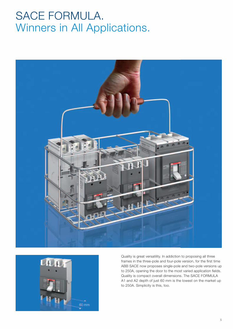
SACE FORMULA. Winners in All Applications.
Quality is great versatility. In addiction to proposing all three frames in the three-pole and four-pole version, for the first time ABB SACE now proposes single-pole and two-pole versions up to 250A, opening the door to the most varied application fields.Quality is compact overall dimensions. The SACE FORMULA A1 and A2 depth of just 60 mm is the lowest on the market up to 250A. Simplicity is this, too.
Formula_00_indice+avanticat.indd 5 21/02/2011 9.36.52


1/11SDC210032D0204
Main characteristics
Content
General information ............................................................................................................. 1/2
Regulations and reference Standards ................................................................................ 1/3
Identification of the SACE FORMULA circuit-breakers ..................................................... 1/4
Formula_01_caratteristiche.indd 1 21/02/2011 9.37.31

1/2
B
A
B
1SD
C21
0610
F000
11S
DC
2106
11F0
001
1SD
C21
0612
F000
11S
DC
2106
13F0
001
1SD
C21
0612
F000
1
1SDC210032D0204
Construction characteristics General information
The references in round brackets (Gx.x) in the technical catalogue refer to the Glossary in the final charter of the technical catalogue.
All the moulded-case circuit-breakers in the SACE FORMULA family are constructed in ac-cordance with the following construction characteristics: • double insulation(G1.4);• positive operation(G1.5);• isolation behaviour(G1.6);• electromagnetic compatibility(G1.7);• tropicalization(G1.8);• power supply from the top towards the bottom or vice versa;• versatility of the installation. It is possible to mount the circuit-breaker either in the horizontal,
vertical, or lying down position without undergoing any derating of the rated characteristics;• no nominal performance derating for use up to an altitude of 2000m. Above 2000m, the
properties of the atmosphere (composition of the air, dielectric strength, cooling power and pressure) change, having an impact on the main parameters which define the circuit-breaker. The table below gives the changes to the main performance parameters;
• SACE FORMULA circuit-breakers can be used in ambient with a temperature between -25°C +70°C and stored in a room with atmospheric temperature between -40°C +70°C. SACE FORMULA circuit-breakers listed below are designed to hold 100% In at 50°C without tripping in normal condition:
- SACE A1 and A2, up to 250A (except A1 125); - SACE A3 300-400A special version 50°C. For detailed temperature performances of all SACE FORMULA breakers, please refer to
paragraph “Temperature performances” in the Characteristic Curves and Technical Informa-tion Chapter;
• different protection degrees IP (International Protection) (G1.2);
Altitude 2000m 3000m 4000m 5000m
A1-A2-A3 A1-A2-A3 A1-A2-A3 A1-A2-A3
Rated service voltage, Ue [V] 550 484 429 374
Rated uninterrupted current % 100 98 95 90
• circuit-breaker weights;
Circuit-breaker with front
Circuit-breaker without front (1)
Circuit-breaker with RHE RHD
Circuit-breaker with HTC
Circuit-breaker with LTC
Circuit-breaker with FLD
A IP 40 IP 20 IP 40 IP 40 IP 40 IP 40
B IP 20 IP 20 IP 20 IP 40 IP 30 IP 20
(1) During installation of the electrical accessories
Weights A1 [Kg] A2 [Kg] A3 [Kg]
Circuit-breaker 1 pole 0.245 0.37 -
Circuit-breaker 2 poles 0.47 0.73 -
Circuit-breaker 3 poles 0.7 1.1 3.25
Circuit-breaker 4 poles 0.925 1.145 4.15
Installation positions
Double insulation
Positive operation
Protection degrees
Test pushbotton
• all the SACE FORMULA circuit-breakers are fitted with a Test pushbutton which allows the release test to be done. This test must be carried out with the circuit-breaker closed.
Formula_01_caratteristiche.indd 2 21/02/2011 9.37.34
1/31SDC210032D0204
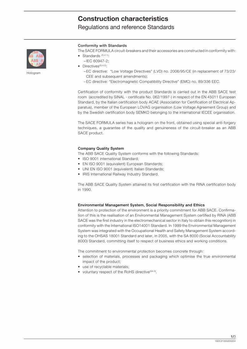
Conformity with StandardsThe SACE FORMULA circuit-breakers and their accessories are constructed in conformity with:• Standards (G.4.1): – IEC 60947-2;• Directives(G.4.2): – EC directive: “Low Voltage Directives” (LVD) no. 2006/95/CE (in replacement of 73/23/
CEE and subsequent amendments); – EC directive: “Electromagnetic Compatibility Directive” (EMC) no. 89/336 EEC.
Certification of conformity with the product Standards is carried out in the ABB SACE test room (accredited by SINAL - certificate No. 062/1997-) in respect of the EN 45011 European Standard, by the Italian certification body ACAE (Association for Certification of Electrical Ap-paratus), member of the European LOVAG organisation (Low Voltage Agreement Group) and by the Swedish certification body SEMKO belonging to the international IECEE organisation.
The SACE FORMULA series has a hologram on the front, obtained using special anti-forgery techniques, a guarantee of the quality and genuineness of the circuit-breaker as an ABB SACE product.
Company Quality SystemThe ABB SACE Quality System conforms with the following Standards:• ISO 9001 international Standard;• EN ISO 9001 (equivalent) European Standards;• UNI EN ISO 9001 (equivalent) Italian Standards;• IRIS International Railway Industry Standard.
The ABB SACE Quality System attained its first certification with the RINA certification body in 1990.
Environmental Management System, Social Responsibility and EthicsAttention to protection of the environment is a priority commitment for ABB SACE. Confirma-tion of this is the realisation of an Environmental Management System certified by RINA (ABB SACE was the first industry in the electromechanical sector in Italy to obtain this recognition) in conformity with the International ISO14001 Standard. In 1999 the Environmental Management System was integrated with the Occupational Health and Safety Management System accord-ing to the OHSAS 18001 Standard and later, in 2005, with the SA 8000 (Social Accountability 8000) Standard, committing itself to respect of business ethics and working conditions.
The commitment to environmental protection becomes concrete through:• selection of materials, processes and packaging which optimise the true environmental
impact of the product;• use of recyclable materials; • voluntary respect of the RoHS directive(G4.3).
Hologram
Construction characteristics Regulations and reference Standards
Formula_01_caratteristiche.indd 3 21/02/2011 9.37.35

1/4
In=100A
7
3
4
135
67
11
122814
10
9
1
7
4
513
10
3
14
9
1
6
1SD
C21
0614
F000
1
1SD
C21
0615
F000
1
15
1SDC210032D0204
Construction characteristics Identification of the SACE FORMULA circuit-breakers
The characteristics of the circuit-breakers are given on the label on the front of the circuit-breaker, and on the side label.
1. Name of the circuit-breaker and performance level;
2. In: rated uninterrupted current*;3. Uimp: rated impulse withstand
voltage*;4. Ui: insulation voltage*;5. Ics: rated short-circuit service
breaking capacity*;6. Icu: rated ultimate short-circuit
breaking capacity*; 7. Ue: rated service voltage*;8. Symbol of isolation behaviour*;9. Reference Standard IEC 60947-2*;10. Serial number;11. Anti-forgery;12. Test pushbutton;13. Category of use;14. CE Marking;15. Utilization at 50°C (except for A1
125A).
* in compliance with the IEC 60947-2 Standard
Front label
Side label
Formula_01_caratteristiche.indd 4 21/02/2011 9.37.35

2/11SDC210032D0204
Circuit-breakers for power distribution
Content
General characteristics ..................................................................................................... 2/2
Thermomagnetic trip units ............................................................................................... 2/4
Ordering codes ................................................................................................................ 2/5
Electronic trip units ............................................................................................................ 2/9
Ordering codes ................................................................................................................ 2/9
Formula_02_gamma.indd 1 21/02/2011 9.38.07

2/2
SACE FORMULA A1
SACE FORMULA A2
SACE FORMULA A3
1SDC210032D0204
Circuit-breakers for power distributionGeneral characteristics
The SACE FORMULA circuit-breakers from 15A to 630A consist of the interruption part together with the trip unit and they can be installed:• directly on the back plate of the cubicles;• on a DIN rail (A1 and A2);• back door (A1, A2 and A3, 2-3 4 poles).
They are characterised by: • fixed version; • polarity: 1 pole (A1 and A2), 2 poles (A1 and A2), 3 poles (A1, A2 and A3), 4 poles (A1, A2
and A3);• maximum breaking capacity of 36kA for A1 and A2 and of 50kA for A3 at 415V AC;• fixed thermomagnetic trip unit (TMF) for protection of networks in alternating and direct
current (A1, A2, A3);• ELT LI electronic trip unit with fixed thresholds for the protection of networks in alternating
current (A3); • only two depths: 60mm (A1, A2) and 103.5mm (A3); • standard front terminals;• the possibility of use at 50°C without derating up to 250A (except for A1 125A); • a special version for A3 300A-400A for use at 50°C.
4 poles1 pole 2 poles 3 poles
4 poles1 pole 2 poles 3 poles
4 poles3 poles
Formula_02_gamma.indd 2 21/02/2011 9.38.13

2/3
W D
H
1SDC210032D0204
A1 A2 A3
Frame size (G2.1) [A] 125 250 400/630
Rated current, In (G2.2) [A] 15...125 125...250 320...630
Poles [Nr] 1, 2, 3, 4 1, 2, 3, 4 3, 4
Rated service voltage, Ue (G2.3) (AC) 50-60 Hz [V] 550 (2p-3p-4p); 415 (1p) 550 (2p-3p-4p); 415 (1p) 550
(DC) [V] 250 (2p-3p-4p); 125 (1p) 250 (2p-3p-4p); 125 (1p) 250
Rated insulation voltage, Ui (G2.4) [V] 690 690 690
Rated impulse withstand voltage, Uimp (G2.5) [kV] 6 6 6
Versions Fixed Fixed Fixed
Performance Level A B C N B C N N S
Poles [Nr] 3/4 3/4 1 3/4 1 2 3/4 3/4 1 3/4 1 2 3/4 3/4 3/4
Rated ultimate short-circuit breaking capacity, Icu (G2.6)
Icu @ 240 V 50-60 Hz (AC) [kA] 10 25 18 30 25 50 100 25 18 50 25 50 85 85 100
Icu @ 380 V 50-60 Hz (AC) [kA] 10 18 2.5 25 5 36(5) 36(5) 18 2.5 25 5 36 36 36 50
Icu @ 415 V 50-60 Hz (AC) [kA] 10 18 2.5 25 5 36(5) 36(5) 18 2.5 25 5 36 36 36 50
Icu @ 440 V 50-60 Hz (AC) [kA] 8 15 - 20 - 25 25 15 - 20 - 25 25 36 50
Icu @ 480 V 50-60 Hz (AC) [kA] 7.5 10 - 15 - 18 18 15 - 18 - 18 25 25 35
Icu @ 500 V 50-60 Hz (AC) [kA] 5 5 - 8 - 10 10 5 - 8 - 10 10 20 25
Icu @ 550 V 50-60 Hz (AC) [kA] 5 5 - 8 - 10 10 5 - 8 - 10 10 15 20
Icu @ 125 V (DC) 1 pole [kA] - - 5 - 10 - - - 5 - 10 - - - -
Icu @ 250 V (DC) 2 poles in series [kA] 5 5 - 10 - 10 10 18 - 25 - 10 36 36 50
Rated short-circuit service breaking capacity, Ics (G2.7)
Ics @ 240 V 50-60 Hz (AC) [kA] 50% 50% 50% 50% 50% 50% 50% 50% 50% 50% 50% 50% 50% 50% 50%
Ics @ 380 V 50-60 Hz (AC) [kA] 50% 50% 50% 50% 50% 50% 50% 50% 100% 50% 50% 50% 50% 50% 50%
Ics @ 415 V 50-60 Hz (AC) [kA] 50% 25%(1) 50% 25%(2) 25% 25% 25% 50% 100% 50% 50% 50% 50% 50% 50%
Ics @ 440 V 50-60 Hz (AC) [kA] 50% 25%(1) - 25% - 25% 25% 50% - 50% - 50% 50% 50% 50%
Ics @ 480 V 50-60 Hz (AC) [kA] 50% 50% - 25%(1) - 25% 25%(1) 50% - 50% - 50% 50% 50% 50%
Ics @ 500 V 50-60 Hz (AC) [kA] 50% 50% - 25%(3) - 25% 25% 50% - 50% - 50% 50% 50% 50%
Ics @ 550 V 50-60 Hz (AC) [kA] 50% 50% - 25%(3) - 25% 25% 50% - 50% - 50% 50% 50% 50%
Ics @ 250 V (DC) 2 poles in series [kA] 50% 50% 50% 50% 50% 50% 50% 50% 50% 50% 50% 50% 50% 50% 50%
Rated short-circuit making capacity, Icm (G2.8)
Icm @ 240 V 50-60 Hz (AC) [kA] 52.5 52.5 36 63 52.5 105 220 52.5 36 105 52.5 105 187 187 220
Icm @ 380 V 50-60 Hz (AC) [kA] 17 36 3.8 52.5 7.5 75.6 75.6 36 3.8 52.5 7.5 75.6 75.6 75.6 105
Icm @ 415 V 50-60 Hz (AC) [kA] 17 36 3.8 52.5 7.5 63 63 36 3.8 52.5 7.5 75.6 75.6 75.6 105
Icm @ 440 V 50-60 Hz (AC) [kA] 13.6 30 - 40 - 52.5 52.5 30 - 40 - 52.5 52.5 75.6 105
Icm @ 480 V 50-60 Hz (AC) [kA] 12.8 17 - 30 - 36 17 30 - 36 - 36 52.5 52.5 73.5
Icm @ 500 V 50-60 Hz (AC) [kA] 7.5 7.5 - 13.6 - 17 17 7.5 - 13.6 - 17 17 40 52.5
Icm @ 550 V 50-60 Hz (AC) [kA] 7.5 7.5 - 13.6 - 17 17 7.5 - 13.6 - 17 17 30 40
Utilization category (IEC 60947-2) (G2.9) A A A
Hold 100% In at 50°C [A] 15...100 125...250 300-400(4)
Reference Standard IEC 60947-2 IEC 60947-2 IEC 60947-2
Isolation behaviour
Fixing onto DIN rail DIN EN 50022 DIN EN 50022 -
Mechanical life (G2.10) [No. operations] 8500 10000 5000
Electrical life @ 415 V (AC) (G2.11) [No. operations] 1500 4000 2000
Total opening time Shunt opening release (SOR) [ms] 15 15 15
Undervoltage release (UVR) [ms] 15 15 < 25
Dimensions (Width x Depth x Height)
1 pole [mm] 25.4x60x130 35x60x150 -
2 poles [mm] 50.8x60x130 70x60x150 -
3 poles [mm] 76.2x60x130 105x60x150139.5x103.5x
205
4 poles [mm] 101.6x60x130 140x60x150 186x
103.5x205
Weight
1 pole [kg] 0.245 0.370 -
2 poles [kg] 0.470 0.730 -
3 poles [kg] 0.700 1.100 3.25
4 poles [kg] 0.925 1.450 4.15
Trip Unit (G3.1)
Thermomagnetic TMF (G3.2) (up to 500A)
Electronic ELT LI (G3.3) (up to 630A)
(1) 5kA; (2) 9kA; (3) 2.5kA; (4) Special version; (5) In=15A, Icu=30kA
Formula_02_gamma.indd 3 21/02/2011 9.38.15

2/4
1SD
C21
0626
F000
1
1SDC210032D0204
The thermomagnetic trip units TMF, available for A1, A2 and A3, with fixed thermal and magnetic threshold, are generally used in power distribution plants. They allow protection against overloads thanks to the thermal device and protection against short-circuit thanks to magnetic device: • thermal protection (L): fixed threshold I1= 1x1In, with long inverse time trip curve;• magnetic protection (I): fixed threshold I3= 10xIn, with instantaneous trip curve;• neutral at 100% for four-pole circuit-breakers.
Circuit-breakers for power distributionThermomagnetic trip unit
SACE FORMULA A1 with trip unit TMFTMF
I1= 1xIn
In [A] 15 16 20 25 30 32 40 50 60 63 70 80 90 100 125
Neutral [A] - 100% 15 16 20 25 30 32 40 50 60 63 70 80 90 100 125
I3= 10xIn
I3 [A] 300 300 300 300 300 320 400 500 600 630 700 800 900 1000 1250
Neutral [A] - 100% 300 300 300 300 300 320 400 500 600 630 700 800 900 1000 1250
SACE FORMULA A2 with trip unit TMFTMF
I1= 1xIn
In [A] 125 150 160 175 200 225 250
Neutral [A] - 100% 125 150 160 175 200 225 250
I3= 10xIn
I3 [A] 1250 1500 1600 1750 2000 2250 2500
Neutral [A] - 100% 1250 1500 1600 1750 2000 2250 2500
SACE FORMULA A3 with trip unit TMFTMF
I1= 1xIn
In [A] 320 400 500
Neutral [A] - 100% 320 400 500
I3= 10xIn
I3 [A] 3200 4000 5000
Neutral [A] - 100% 3200 4000 5000
Magnetic protection symbol
Magnetic protection value
Thermal protection value
Thermal protection symbol
Fixed thermomagnetic trip unit TMFAn example with SACE FORMULA A1 In=125A
Formula_02_gamma.indd 4 21/02/2011 9.38.16

2/5
1SD
C21
0627
F000
1
1SD
C21
0628
F000
1
1SDC210032D0204
A1 125A - Fixed (F) 1 pole - Front terminals (F) - Hold 100% In at 50°C
Thermomagnetic trip unit - TMF Icu (240 V)
1SDA...R1
In I3 C (18kA) N (25kA)
15 400 066485
16 400 068745
20 400 066486 066686
25 400 066487 066687
30 400 066488 066688
32 400 068754 068755
40 400 066489 066689
50 500 066490 066690
60 600 066491 066691
63 630 068765 068766
70 700 066492 066692
80 800 066493 066693
90 900 066494 066694
100 1000 066495 066695
125 1250 066496 (1) 066696 (1)
(1) Derating for use at 50°C
A1 125A - Fixed (F) 2 poles - Front terminals (F) - Hold 100% In at 50°C
Thermomagnetic trip unit - TMF Icu (415 V)
1SDA...R1
In I3 N (36kA)
15 400 068789 (2)
16 400 068790
20 400 066497
25 400 066498
30 400 066499
32 400 068756
40 400 066500
50 500 066501
60 600 066502
63 630 068767
70 700 066503
80 800 066504
90 900 066505
100 1000 066506
125 1250 066507 (1)
(1) Derating for use at 50°C; (2) 30kA
Ordering codes for circuit-breakers with thermomagnetic trip units
Formula_02_gamma.indd 5 21/02/2011 9.38.17

2/6
1SD
C21
0629
F000
1
1SD
C21
0630
F000
1
1SDC210032D0204
A1 125A - Fixed (F) 3 poles - Front terminals (F) - Hold 100% In at 50°C
Thermomagnetic trip unit - TMF Icu (415 V)
1SDA...R1
In I3 A (10kA) B (18kA) C (25kA) N (36kA)
15 300 066510 066697 066709 066721 (2)
16 300 068746 068747 068748 068749 (2)
20 300 066511 066698 066710 066722
25 300 066512 066699 066711 066723
30 300 066513 066700 066712 066724
32 320 068757 068758 068759 068760
40 400 066514 066701 066713 066725
50 500 066515 066702 066714 066726
60 600 066516 066703 066715 066727
63 630 068768 068769 068770 068771
70 700 066517 066704 066716 066728
80 800 066518 066705 066717 066729
90 900 066519 066706 066718 066730
100 1000 066520 066707 066719 066731
125 1250 066521 (1) 066708 (1) 066720 (1) 066732 (1)
(1) Derating for use at 50°C; (2) 30kA
Circuit-breakers for power distributionThermomagnetic trip unit
A1 125A - Fixed (F) 4 poles - Front terminals (F) - Hold 100% In at 50°C
Thermomagnetic trip unit - TMF Icu (415 V)
1SDA...R1
In I3 A (10kA) B (18kA) C (25kA) N (36kA)
15 300 066524 066733 066745 066757 (2)
16 300 068750 068751 068752 068753 (2)
20 300 066525 066734 066746 066758
25 300 066526 066735 066747 066759
30 300 066527 066736 066748 066760
32 320 068761 068762 068763 068764
40 400 066528 066737 066749 066761
50 500 066529 066738 066750 066762
60 600 066530 066739 066751 066763
63 630 068772 068773 068774 068775
70 700 066531 066740 066752 066764
80 800 066532 066741 066753 066765
90 900 066533 066742 066754 066766
100 1000 066534 066743 066755 066767
125 1250 066535 (1) 066744 (1) 066756 (1) 066768 (1)
(1) Derating for use at 50°C; (2) 30kA
Ordering codes for circuit-breakers with thermomagnetic trip units
Formula_02_gamma.indd 6 21/02/2011 9.38.18

2/7
1SD
C21
0631
F000
1
1SD
C21
0632
F000
1
1SD
C21
0633
F000
1
1SD
C21
0634
F000
1
1SDC210032D0204
A2 250A - Fixed (F) 3 poles - Front terminals (F) - Hold 100% In at 50°C
Thermomagnetic trip unit - TMF Icu (415 V)
1SDA...R1
In I3 B (18kA) C (25kA) N (36kA)
125 1250 066548 066775 066781
150 1500 068779 068780 068781
160 1600 066549 066776 066782
175 1750 066550 066777 066783
200 2000 066551 066778 066784
225 2250 066552 066779 066785
250 2500 066553 066780 066786
A2 250A - Fixed (F) 1 pole - Front terminals (F) - Hold 100% In at 50°C
Thermomagnetic trip unit - TMF Icu (240 V)
1SDA...R1
In I3 C (18kA) N (25kA)
125 1250 066536 066769
150 1500 068776 068777
160 1600 066537 066770
175 1750 066538 066771
200 2000 066539 066772
225 2250 066540 066773
250 2500 066541 066774
A2 250A - Fixed (F) 2 poles - Front terminals (F) - Hold 100% In at 50°C
Thermomagnetic trip unit - TMF Icu (415 V)
1SDA...R1
In I3 N (36kA)
125 1250 066542
150 1500 068778
160 1600 066543
175 1750 066544
200 2000 066545
225 2250 066546
250 2500 066547
A2 250A - Fixed (F) 4 poles - Front terminals (F) - Hold 100% In at 50°C
Thermomagnetic trip unit - TMF Icu (415 V)
1SDA...R1
In I3 B (18kA) C (25kA) N (36kA)
125 1250 066554 066787 066793
150 1500 068782 068783 068784
160 1600 066555 066788 066794
175 1750 066556 066789 066795
200 2000 066557 066790 066796
225 2250 066558 066791 066797
250 2500 066559 066792 066798
Formula_02_gamma.indd 7 21/02/2011 9.38.21

2/8
1SD
C21
0635
F000
1
1SD
C21
0636
F000
1
1SDC210032D0204
A3 400A - Fixed (F) 3 poles - Front terminals (F)
Thermomagnetic trip unit - TMF Icu (415 V)
1SDA...R1
In I3 N (36kA) S (50kA)
320 3200 066560 066562
400 4000 066561 066563
A3 630A - Fixed (F) 3 poles - Front terminals (F)
Thermomagnetic trip unit - TMF Icu (415 V)
1SDA...R1
In I3 N (36kA) S (50kA)
500 5000 066564 066565
Circuit-breakers for power distributionThermomagnetic trip unit
A3 400A - Fixed (F) 4 poles - Front terminals (F)
Thermomagnetic trip unit - TMF Icu (415 V)
1SDA...R1
In I3 N (36kA) S (50kA)
320 3200 066568 066570
400 4000 066569 066571
A3 630A - Fixed (F) 4 poles - Front terminals (F)
Thermomagnetic trip unit - TMF Icu (415 V)
1SDA...R1
In I3 N (36kA) S (50kA)
500 5000 066572 066573
Ordering codes for circuit-breakers with thermomagnetic trip units
A3 400A - Fixed (F) 3 poles - Front terminals (F) - Hold 100% In at 50°C
Thermomagnetic trip unit - TMF Icu (415 V)
1SDA...R1
In I3 N (36kA) S (50kA)
300 3000 068809 068960
400 4000 068810 068961
Ordering codes A3 special version 50°C
Formula_02_gamma.indd 8 21/02/2011 9.38.22

2/9
1SD
C21
0637
F000
1
1SD
C21
0638
F000
1
1SDC210032D0204
The ELT LI electronic trip unit, only available for A3, provides protection functions against overload L and short-circuit I: • protection against overload (L): fixed threshold I1=630A, with long inverse time trip curve;• protection against short-circuit (I): fixed threshold I3=6000A, with instantaneous time trip curve;• neutral at 100% for four-pole circuit-breakers.
Circuit-breakers for power distributionElectronic trip unit
A3 630A - Fixed (F) 3 poles - Front terminals (F)
Electronic trip unit - ELT LI Icu (415 V)
1SDA...R1
In I3 N (36kA) S (50kA)
630 6000 066566 066567
A3 630A - Fixed (F) 4 poles - Front terminals (F)
Electronic trip unit - ELT LI Icu (415 V)
1SDA...R1
In I3 N (36kA) S (50kA)
630 6000 066574 066575
SACE FORMULA A3 with trip unit ELT LIProtection function Trip threshold Trip curve Excludability Relation
Against overload with long inverse time delay trip according to IEC 60947-2 Standard
Fixed thresholdI1=630A
Tolerance: trip between 1.1...1.30xI1
t1= 12 s at 6xI1Tolerance:
± 10% up to 6xIn± 20% above 6xIn
no t=k/l2
Against short-circuit with instantaneous trip with fixed threshold
Fixed thresholdI3=6000A
Tolerance: ± 10%instantaneous no t=k
Ordering codes for circuit-breakers with electronic trip units
Protection against overload value
Protection against short-circuit value
ELT LI fixed electronic trip unitAn example with SACE FORMULA A3 In=630A
Trip test unit 1SDA...R1
TT1 - Trip test unit 037121
Socket for TT1 test unit
Formula_02_gamma.indd 9 21/02/2011 9.38.25
Top Related