


Languages
Pages
Legal

S 01 Module Washbasin
GB Installation Instructions

GB S 01
S 01 / WT Module Installation Instructions MS01.08G B
2 | HEWI 03/2014
Contents 1 Introduction ....................................... ........................................................................... 4
About these instructions................................................................................................. 4
Explanation of the symbols and signal words used........................................................ 4
Target group .................................................................................................................. 4
HEWI Support ................................................................................................................ 4
Up-to-date information ................................................................................................... 5
2 Product description ................................ ..................................................................... 6
Purpose and use............................................................................................................ 6
Structure and function .................................................................................................... 6
Versions ......................................................................................................................... 7
Assembly principle ......................................................................................................... 8
S 01 consists of two sets of wall installation and module ............................................... 8
Detailed information ....................................................................................................... 9
3 Intended use....................................... ........................................................................ 10
Area of use................................................................................................................... 10
Condition of the product ............................................................................................... 10
Ambient conditions....................................................................................................... 10
4 Safety ............................................. ............................................................................. 10
5 Scope of supply and installation tools............. ........................................................ 11
6 Planning information ............................... .................................................................. 12
7 Installation ....................................... ........................................................................... 14
Overview ...................................................................................................................... 14
7.1 Set 1 Install prewall ................................................................................................ 14
7.2 Set 2 Install functional elements............................................................................. 27
8 Dismentling........................................ ......................................................................... 42
Note ............................................................................................................................. 42
9 Wartung ............................................ .......................................................................... 43
9.1 Fill paper towel dispenser................................................................................... 43
9.2 Top-up soap ....................................................................................................... 43
9.3 Water installation maintenance .......................................................................... 44
9.4 Open / close „Push and Release“ Paper towel basket ....................................... 44
9.5 Remove „Push and Release“ Paper towel basket ............................................. 45
9.6 Install „Push und Release“ Paper towel basket .................................................. 45
9.7 Open / close „non-contact opening and closing“ paper basket........................... 46
9.8 Remove „non-contact opening and closing“ paper towel basket ........................ 47
9.9 Install „non-contact opening and closing“ paper towel basket ............................ 48
S 01 GB Installation Instructions MS01.08GB S 01 / WT Modul e
03/2014 HEWI | 3
10 Cleaning and maintenance ........................... ..........................................................49
11 Disposal ........................................... ........................................................................49
Electronic components .................................................................................................49
Product packaging........................................................................................................49
12 Product specification .............................. ................................................................50
Technical data ..............................................................................................................50

GB S 01
S 01 / WT Module Installation Instructions MS01.08G B
4 | HEWI 03/2014
1 Introduction About these instructions
These instructions contain important information on the installation of HEWI S01 washbasin modules.
� Carefully read through the instructions before starting the installation work and putting into service.
� Keep these instructions and distribute to appropriate personnel.
Explanation of the symbols and signal words used
WARNING! Indicates hazards which could result in severe or
fatal injuries.
CAUTION! Indicates hazards which could result in damage to property.
Note Indicates information and tips for optimum use of the instructions and the product.
� � �
In tables of step-by-step instructions, establishes the reference between a description of an activity and the figure opposite or immediately below.
Target group Faultless, safe function of the washbasin modules depends to a large extent on proper installation.
These instructions are therefore directed at trained installation engineering or building services personnel or people with comparable training.
HEWI Support If you have any questions which are not answered by the information provided in these instructions, please contact
HEWI Heinrich Wilke GmbH Support Postfach 1260 D-34442 Bad Arolsen
Tel.: +49 5691 82-300 Fax: +49 5691 82-493 E-mail: [email protected]

S 01 GB Installation Instructions MS01.08GB S 01 / WT Modul e
03/2014 HEWI | 5
Up-to-date information All information about the product, images, dimensions and versions is up-to-date and correct at the time of production. We reserve the right to make changes to our products without notice due to technical progress and the resulting continuous improvement process.
The current version of these instructions and further information is also available on our internet site www.hewi.de.
Dated 03/2014
GB S 01
S 01 / WT Module Installation Instructions MS01.08G B
6 | HEWI 03/2014
2 Product description Purpose and use
The HEWI S 01 washbasin module is a dry walling installation system, which integrates various washbasin functions and features in one complete system.
It is based on a standard prewall system.
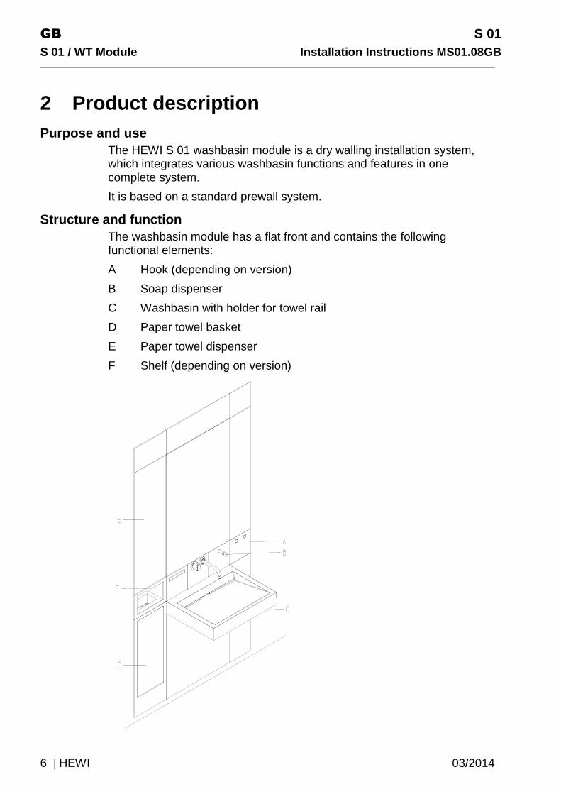
Structure and function The washbasin module has a flat front and contains the following functional elements:
A Hook (depending on version)
B Soap dispenser
C Washbasin with holder for towel rail
D Paper towel basket
E Paper towel dispenser
F Shelf (depending on version)

S 01 GB Installation Instructions MS01.08GB S 01 / WT Modul e
03/2014 HEWI | 7
Versions The following versions of the washbasin module are available.
Name/Description Art. No.
Description Drawing
Washbasin module I S01.01.100… S01.01.101…
Without hook and shelf Paper towel basket Paper towel basket Non-contact opening and closing
Washbasin module II S01.01.200… S01.01.201…
With hook and shelf Paper towel basket Paper towel basket Non-contact opening and closing
GB S 01
S 01 / WT Module Installation Instructions MS01.08G B
8 | HEWI 03/2014
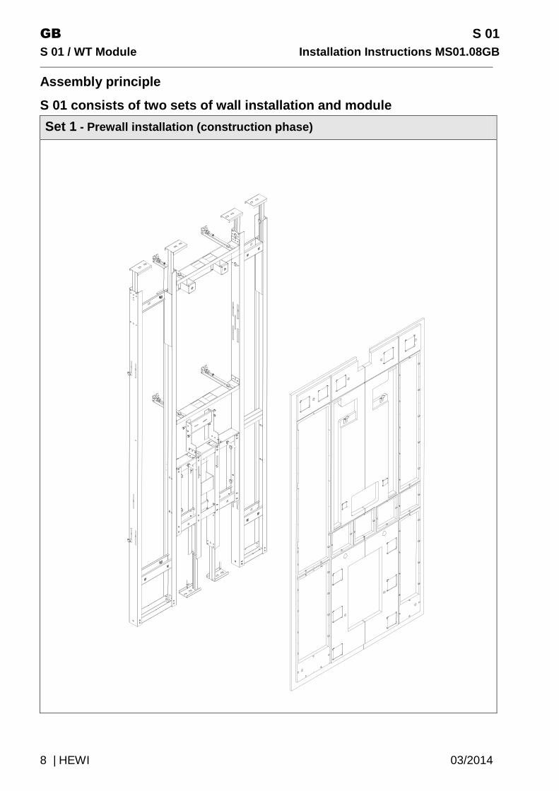
Assembly principle
S 01 consists of two sets of wall installation and module
Set 1 - Prewall installation (construction phase)
S 01 GB Installation Instructions MS01.08GB S 01 / WT Modul e
03/2014 HEWI | 9
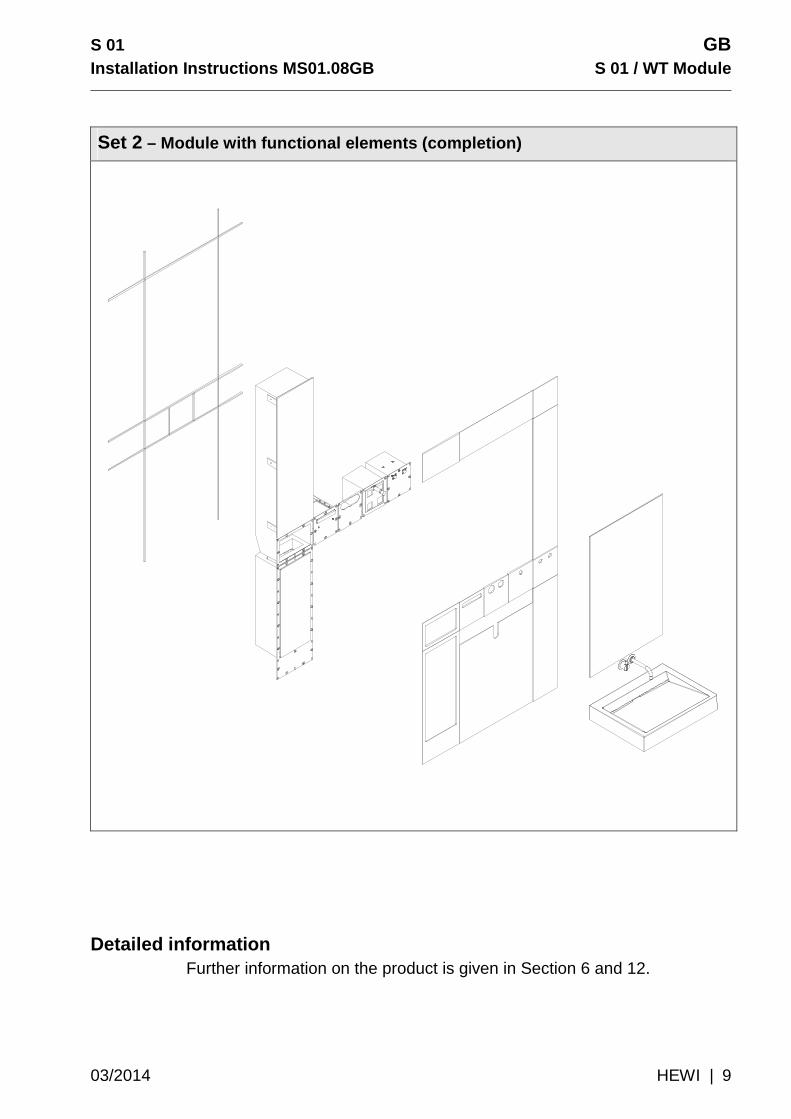
Set 2 – Module with functional elements (completion)
Detailed information Further information on the product is given in Section 6 and 12.

GB S 01
S 01 / WT Module Installation Instructions MS01.08G B
10 | HEWI 03/2014
3 Intended use Area of use
The washbasin module is suitable for installation in dry walling floor and ceiling rails (to be provided on site) or for mounting on floors and walls.
The floor, ceiling and wall fixing materials are designed for concrete and solid sand-lime blocks.
The relevant specifications and guidelines of all trades involved must be taken into account.
Condition of the product The washbasin module may only be used if it is in faultless technical condition.
Independent modifications and changes to the product are not allowed.
Ambient conditions The electrical connections above the module required for the control components must be located at a minimum height of 2250 mm, measured from the finished floor level (OKFFB).
4 Safety The safety instructions in this document must be noted and followed! HEWI does not accept any liability whatsoever for injuries or damage to property that result from disregarding these instructions!
WARNING! Exposed, live cables. Risk of electric shock.
Improper connection of the electrical components can result in health damage. Note and comply with the following instructions: � Work on the electrical components may only be carried
out if they have been disconnected from the power supply.
� Only use components supplied by HEWI.

S 01 GB Installation Instructions MS01.08GB S 01 / WT Modul e
03/2014 HEWI | 11
5 Scope of supply and installation tools
Scope of supply
The scope of supply includes all parts required for installation of the washbasin (WT) module.
The following are to be provided on site:
� 75 mm dry walling floor and ceiling rail, insulation tape � Wall-mounted fittings
The following wall-mounted fittings can be combined with the system: • Vola 111 single lever mixer tap plus 20 mm extension • Jado IQ single lever mixer tap • Hansa Public single lever mixer tap plus 2 roses ø 68 mm • Hansgrohe Axor Uno2 single lever mixer tap • the outlet length may have to be adjusted on site,
recommended length 200 mm
Installation tools required

GB S 01
S 01 / WT Module Installation Instructions MS01.08G B
12 | HEWI 03/2014
6 Planning information The system is suitable for room heights, including finished floor build-up 2570-2800 mm For details of connection sheathing/panels, see drywalling on page 22 Key OKFFB = finished floor level OKRFB = unfinished floor level
Prewall installation
Sketch Dimensions
Note:
� free-standing (independent) installation possible
� if necessary, can be installed with wall fixing
Dimension a=220-247mm Dimension b=120-147mm ensure adequate space for pipes, etc.
� In niches and corners, leave at least 50 mm
space at the side � * max. space for pipes, etc. � fittings height 1.01 m AFFL � Height of siphon approx. 670 mm finished
floor level (OKFFB)
S 01 GB Installation Instructions MS01.08GB S 01 / WT Modul e
03/2014 HEWI | 13
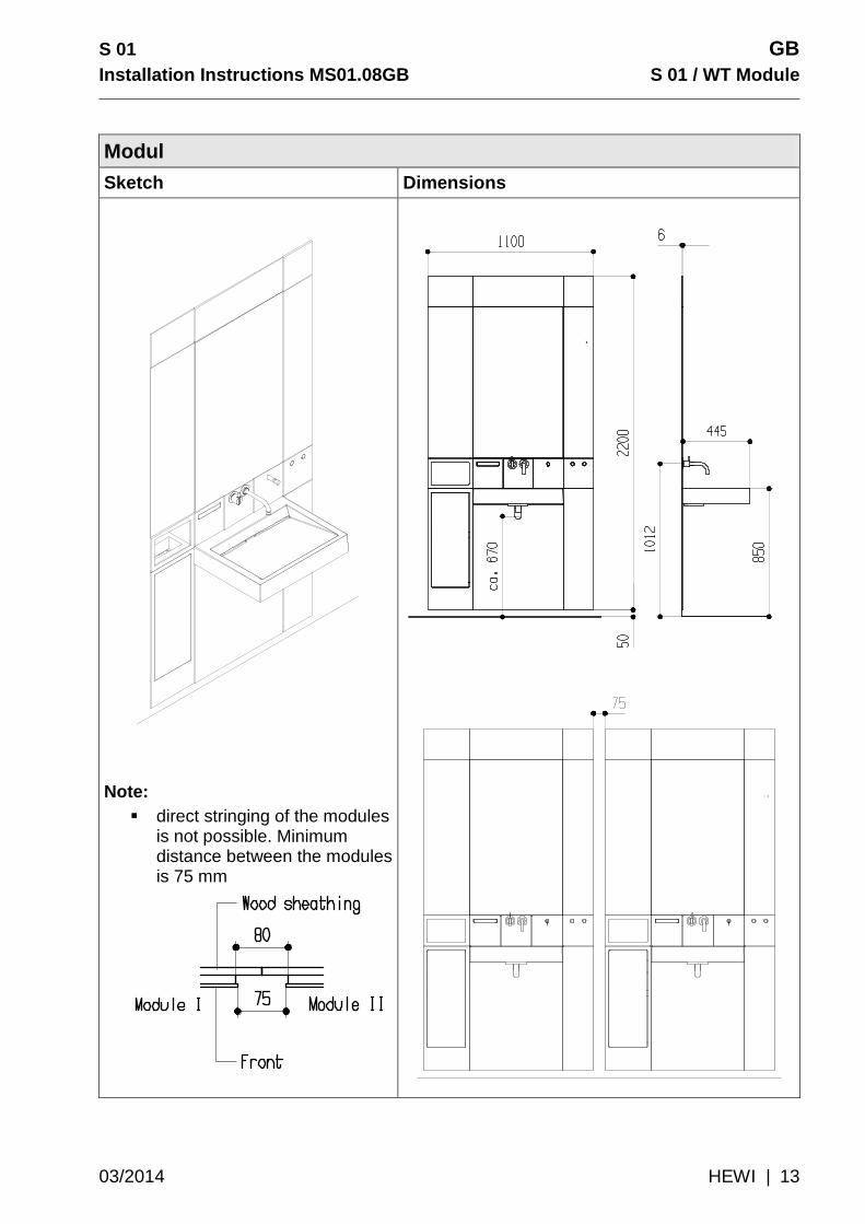
Modul
Sketch Dimensions
Note: � direct stringing of the modules
is not possible. Minimum distance between the modules is 75 mm
GB S 01
S 01 / WT Module Installation Instructions MS01.08G B
14 | HEWI 03/2014
7 Installation
Overview The installation is divided into the following activities:
� Install Set 1 prewall � Install Set 2 functional elements
7.1 Set 1 Install prewall Proceed as follows:
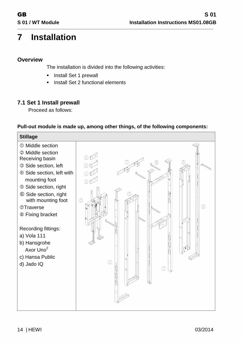
Pull-out module is made up, among other things, of the following components:
Stillage
� Middle section � Middle section Receiving basin � Side section, left � Side section, left with mounting foot � Side section, right
� Side section, right with mounting foot
�Traverse Fixing bracket Recording fittings: a) Vola 111 b) Hansgrohe Axor Uno2 c) Hansa Public d) Jado IQ
S 01 GB Installation Instructions MS01.08GB S 01 / WT Modul e
03/2014 HEWI | 15
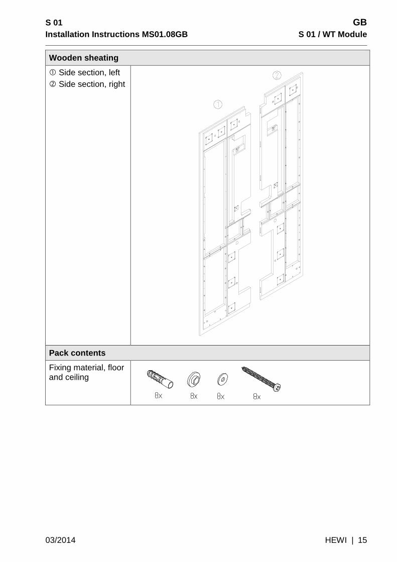
Wooden sheating
� Side section, left � Side section, right
Pack contents
Fixing material, floor and ceiling
GB S 01
S 01 / WT Module Installation Instructions MS01.08G B
16 | HEWI 03/2014
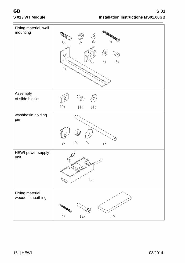
Fixing material, wall mounting
Assembly of slide blocks
washbasin holding pin
HEWI power supply unit
Fixing material, wooden sheathing
S 01 GB Installation Instructions MS01.08GB S 01 / WT Modul e
03/2014 HEWI | 17
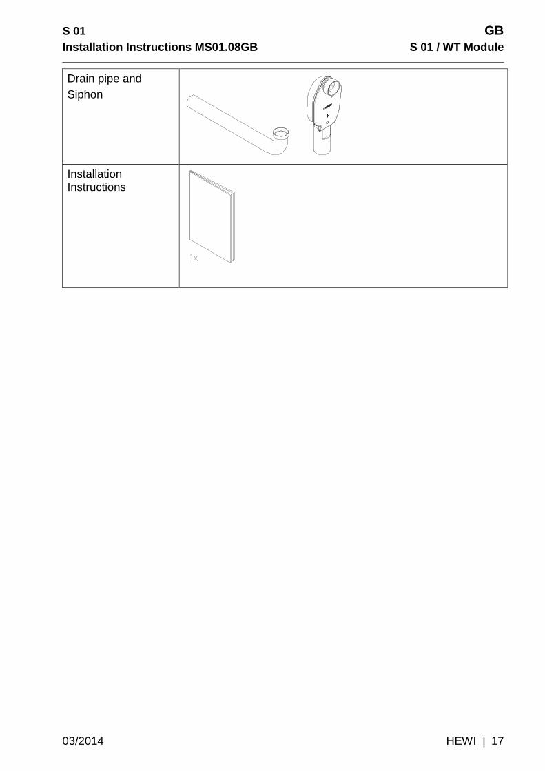
Drain pipe and Siphon
Installation Instructions
GB S 01
S 01 / WT Module Installation Instructions MS01.08G B
18 | HEWI 03/2014
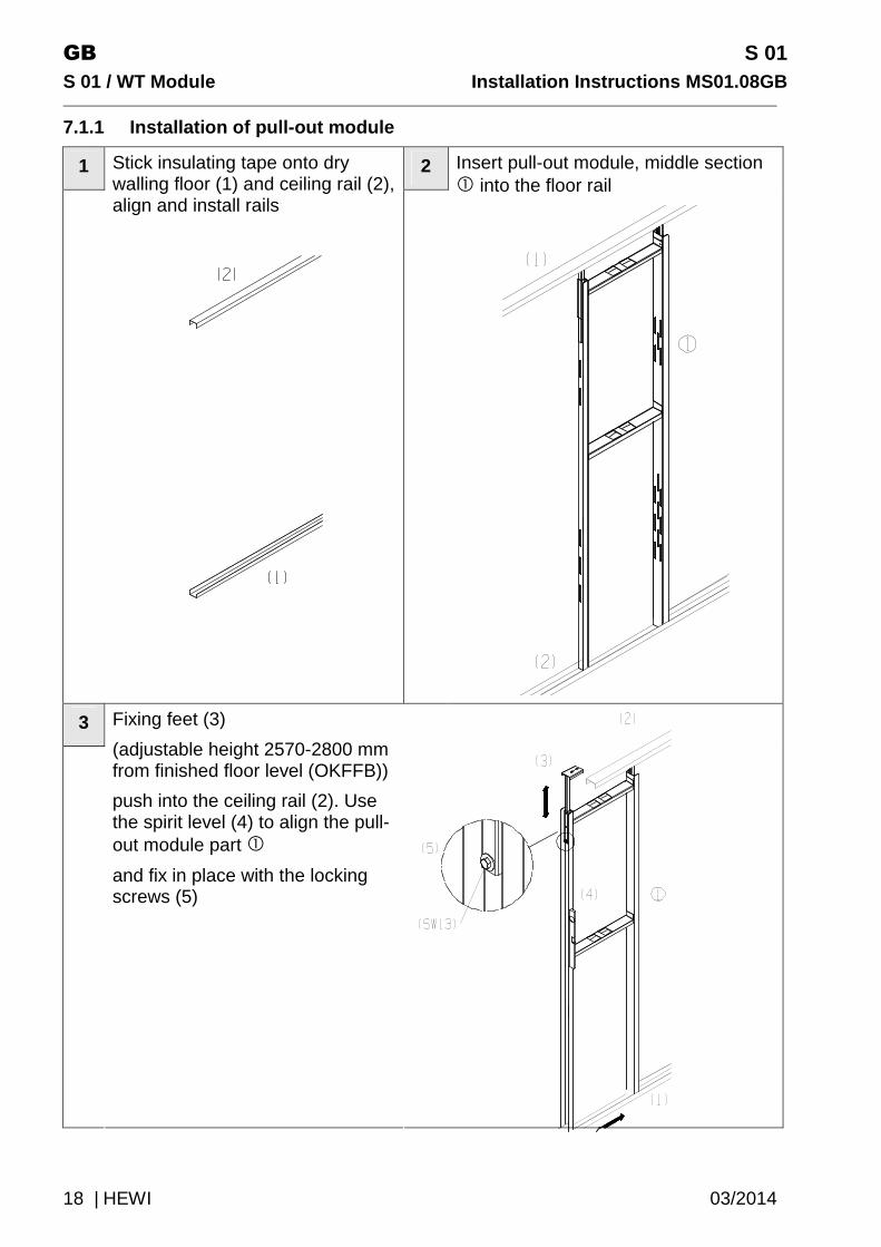
7.1.1 Installation of pull-out module
1 2
Stick insulating tape onto dry walling floor (1) and ceiling rail (2), align and install rails
Insert pull-out module, middle section � into the floor rail
3
Fixing feet (3)
(adjustable height 2570-2800 mm from finished floor level (OKFFB))
push into the ceiling rail (2). Use the spirit level (4) to align the pull-out module part �
and fix in place with the locking screws (5)

S 01 GB Installation Instructions MS01.08GB S 01 / WT Modul e
03/2014 HEWI | 19
4
Adjust part � to the marked level 810 mm OKFFB
5
Place part � in the pull-out module part �and position using the screws
do not yet screw on, not until Step 6

GB S 01
S 01 / WT Module Installation Instructions MS01.08G B
20 | HEWI 03/2014
6
Fix pull-out module, side section, left � and side section, right � at the side
in case of module string and niche installations, Step 6 and 7 must be carried out in one installation step
7
Insert pull-out module part � and � in the floor rail and push the fixing feet (1) into the ceiling rail. Use the spirit level (2) to align and the locking screws (3) to lock the position, then tighten the screws

S 01 GB Installation Instructions MS01.08GB S 01 / WT Modul e
03/2014 HEWI | 21
8
Install cross bracing part � at the rear mount
8
Fasten frame If necessary, wall fixing is possible using angle bracket part with sound isolation (blue rubber element)
GB S 01
S 01 / WT Module Installation Instructions MS01.08G B
22 | HEWI 03/2014
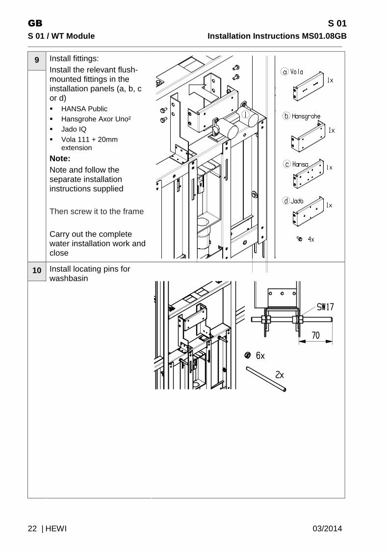
9
Install fittings: Install the relevant flush-mounted fittings in the installation panels (a, b, c or d) � HANSA Public � Hansgrohe Axor Uno² � Jado IQ � Vola 111 + 20mm
extension
Note: Note and follow the separate installation instructions supplied Then screw it to the frame Carry out the complete water installation work and close
10
Install locating pins for washbasin
S 01 GB Installation Instructions MS01.08GB S 01 / WT Modul e
03/2014 HEWI | 23
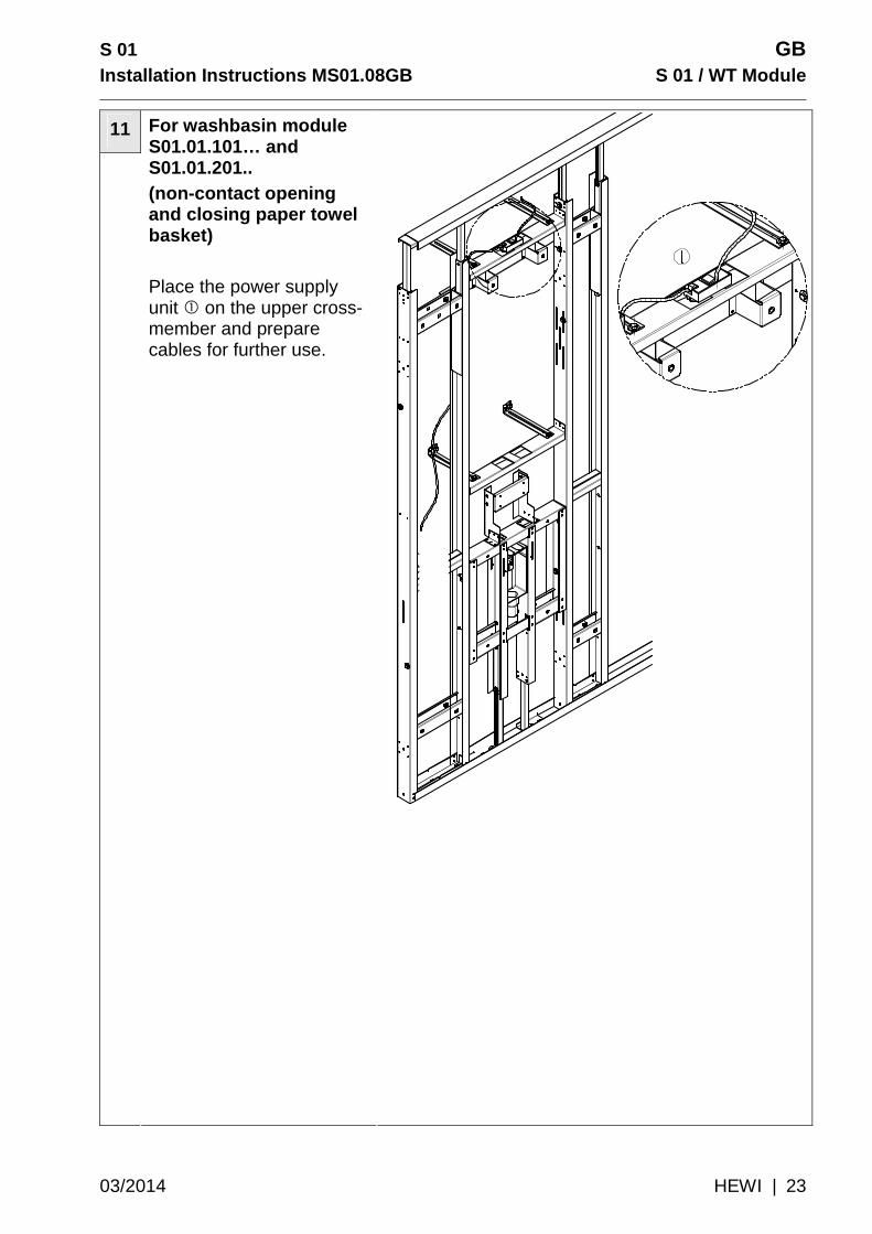
11
For washbasin module S01.01.101… and S01.01.201.. (non-contact opening and closing paper towel basket) Place the power supply unit � on the upper cross-member and prepare cables for further use.

GB S 01
S 01 / WT Module Installation Instructions MS01.08G B
24 | HEWI 03/2014
7.1.2 Installation of wooden planking
1
Use the countersunk screws (1) supplied to fix the wooden sheathing part � and � onto the frame
do not screw on yet
Use the wooden batten (2) to align the wooden sheathing with each other and screw tight
Additionally fix with the wing bolts (3).
.

S 01 GB Installation Instructions MS01.08GB S 01 / WT Modul e
03/2014 HEWI | 25
7.1.3 Drywalling
1
HEWI S 01 Wooden sheathing �
2
Wooden sheathing, provided on site by customer �, gypsum board 12.5 mm
3
Wall covering, provided on site by customer �, e.g. gypsum board sheathing 12,5 mm, tiles < 12,5. mm
� must be flush with �.
4
HEWI S 01 Front panel, acrylic glass �
at join with tile
GB S 01
S 01 / WT Module Installation Instructions MS01.08G B
26 | HEWI 03/2014
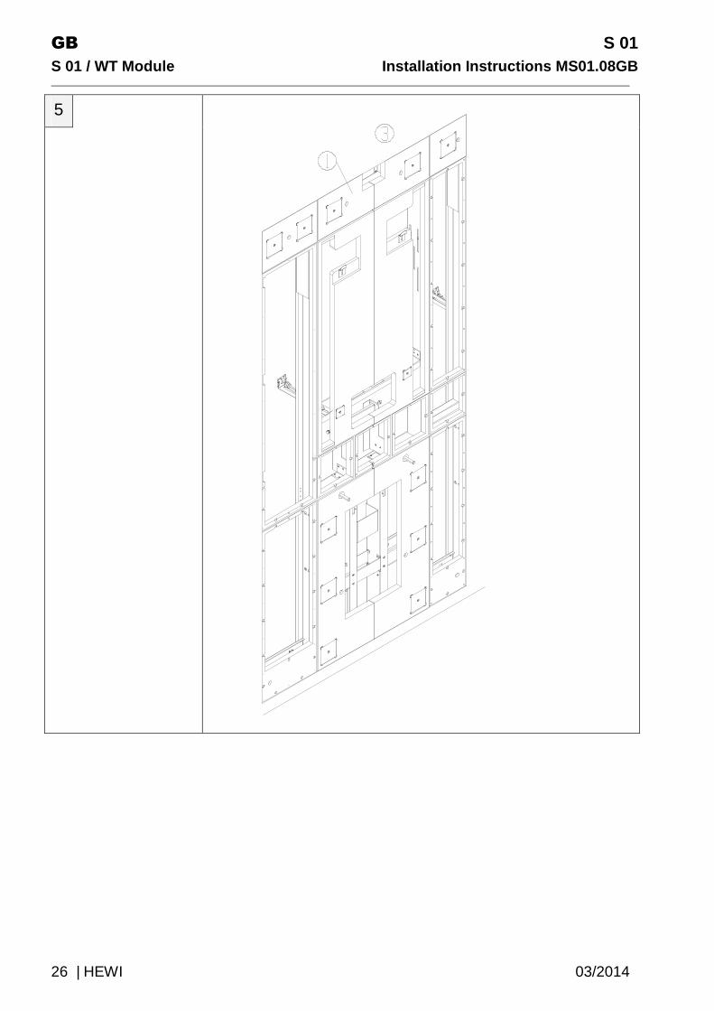
5

S 01 GB Installation Instructions MS01.08GB S 01 / WT Modul e
03/2014 HEWI | 27
7.2 Set 2 Install functional elements Proceed as follows:
Module consists of inter alia the following compone nts:
Functional elements
module S01.01.100… S01.01.101…
module S01.01.200… S01.01.201…
Paper towel dispenser �
1x 1x
Paper towel basket �
1x 1x

GB S 01
S 01 / WT Module Installation Instructions MS01.08G B
28 | HEWI 03/2014
Use paper dispenser � S01.01.100 /.200
S01.01.101 /.201
1x 1x
Shelf �
- 1x
End plate, fittings �
1x 1x
Soap dispenser �
1x 1x
Hooks �
- 1x

S 01 GB Installation Instructions MS01.08GB S 01 / WT Modul e
03/2014 HEWI | 29
Dummy plate
1x 1x
Dummy plate
1x 1x
Dummy plate �
2x -
Washbasin
1x 1x
Mirror
1x 1x
GB S 01
S 01 / WT Module Installation Instructions MS01.08G B
30 | HEWI 03/2014
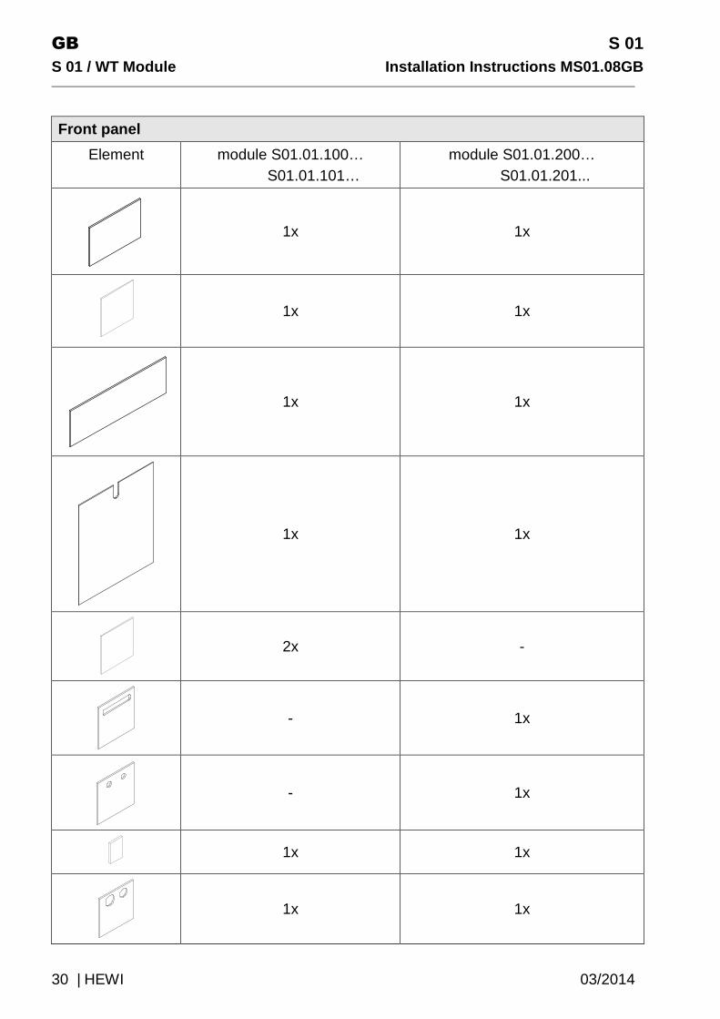
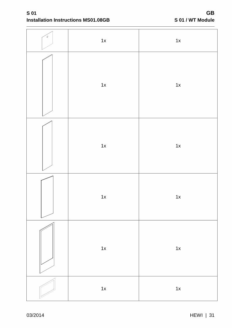
Front panel
Element module S01.01.100… S01.01.101…
module S01.01.200… S01.01.201...
1x 1x
1x 1x
1x 1x
1x 1x
2x -
- 1x
- 1x
1x 1x
1x 1x
S 01 GB Installation Instructions MS01.08GB S 01 / WT Modul e
03/2014 HEWI | 31
1x 1x
1x 1x
1x 1x
1x 1x
1x 1x
1x 1x
GB S 01
S 01 / WT Module Installation Instructions MS01.08G B
32 | HEWI 03/2014
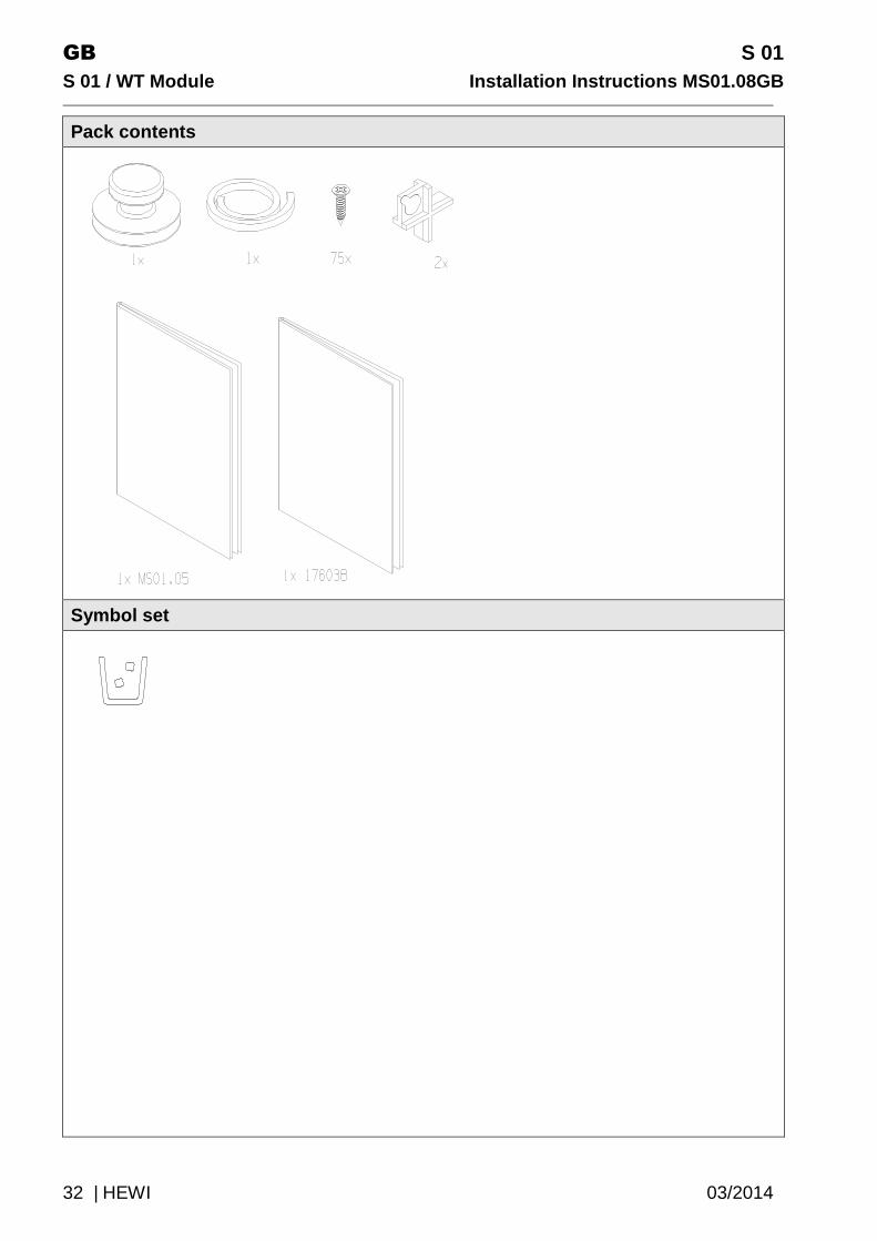
Pack contents
Symbol set

S 01 GB Installation Instructions MS01.08GB S 01 / WT Modul e
03/2014 HEWI | 33
7.2.1 Dichtungsbänder Sealing strips
1
Cut the sealing strips to the required length and insert, without gaps, in the dust-free grooves provided.
(1) 2x 1092 mm (2) 3x 792 mm (3) 5x 192 mm (4) 2x 992 mm (5) 1x 1192 mm (6) 1x 292 mm
Insert the sealing strip into the groove Paper Towel Dispenser, see step 3

GB S 01
S 01 / WT Module Installation Instructions MS01.08G B
34 | HEWI 03/2014
7.2.1 Functional elements
1
Reference: module washbasin S01.01.101.. und S01.01.201
Stick holder at the paper towel dispenser housing Put motion detector into the holder Functional element � Insert paper towel basket �,
lay cables � Lay cables for paper towel
dispenser housing � and insert
Note and follow the separate installation instructions 176038 for the wiring

S 01 GB Installation Instructions MS01.08GB S 01 / WT Modul e
03/2014 HEWI | 35
2
Position functional elements flush on the wooden elements and against the seals
� Paper towel basket � � Paper towe ldispensert � � Shelf � � end plate, fittings � � Soap dispenser � � Hooks � � Dummy plate � Dummy plate In washbasin module I, install the relevant dummy parts instead of the hooks and shelf.
• The functional
elements must not rest on the seals
• Thin-walled surfaces. Risk of stress whitening.
• Use cordless screwdriver at lowest speed level only
• Do not screw in screws too tight.

GB S 01
S 01 / WT Module Installation Instructions MS01.08G B
36 | HEWI 03/2014
3
Insert sailing strip into the groove paper towel dispenser
1x 292 mm
4
Clip the use of paper towel dispensers S01.01.100…
S01.01.200…
S01.01.101…
S01.01.201…

S 01 GB Installation Instructions MS01.08GB S 01 / WT Modul e
03/2014 HEWI | 37
7.2.1 Front panel
1
Use magnets or click-stop points to fix fronts in the order given on the right.
do not use silicone!
• The positioning aids
supplied can be used to align the fronts.
GB S 01
S 01 / WT Module Installation Instructions MS01.08G B
38 | HEWI 03/2014
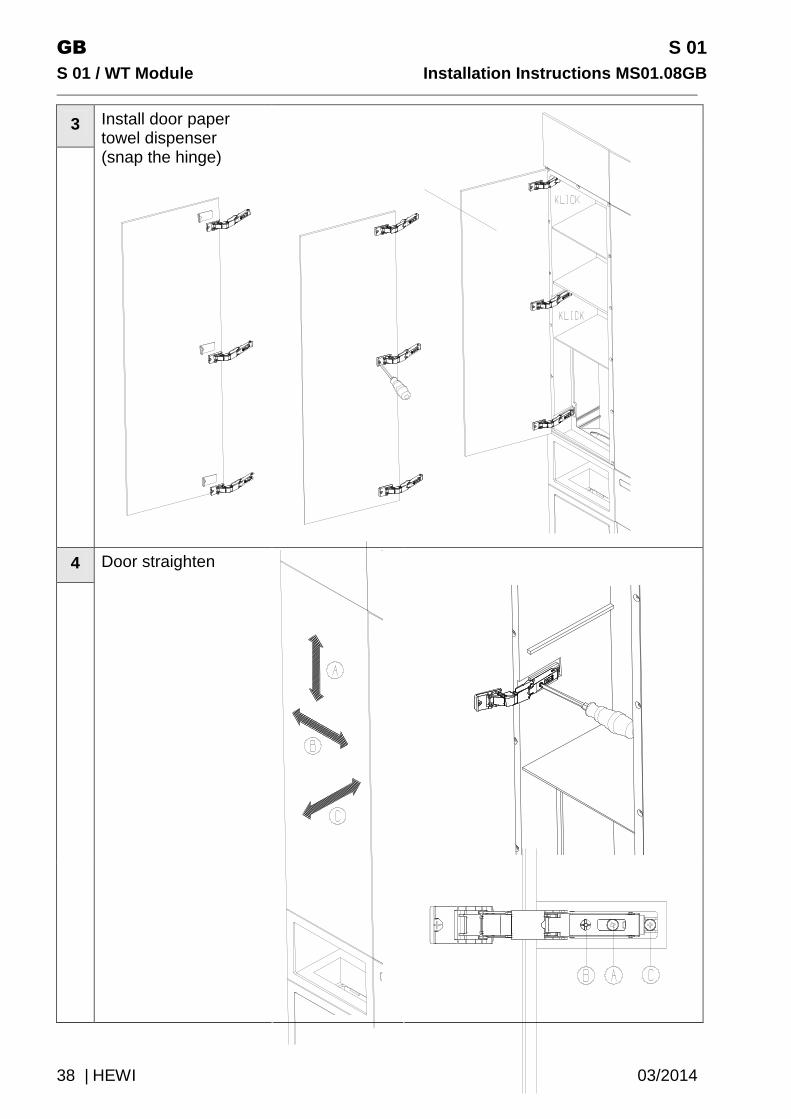
3
Install door paper towel dispenser (snap the hinge)
4
Door straighten

S 01 GB Installation Instructions MS01.08GB S 01 / WT Modul e
03/2014 HEWI | 39
7.2.1 Fitting, washbasin and mirror
1
Install fittings (to be provided on site by others)
Separate installation instructions of the manufacturer.
If necessary, adjust the outlet length on site; max length 200mm:
• Vola 111 single lever mixer tap plus 20 mm extension • Jado IQ single lever mixer tap • Hansa Public single lever mixer tap plus 2 roses ø 68 mm • Hansgrohe Axor Uno2 single lever mixer tap
2
Install washbasin

GB S 01
S 01 / WT Module Installation Instructions MS01.08G B
40 | HEWI 03/2014
3
Fix outlet pipe in accordance with installation instructions supplied
4
Align the front of the washbasin and fix
5
Front (a) :
Pull film off sticky pad and fix onto wooden panel
6a
Hook in mirror � and if necessary align. Then install front � using positioning aid provided.
S 01 GB Installation Instructions MS01.08GB S 01 / WT Modul e
03/2014 HEWI | 41
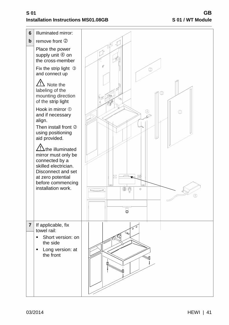
6
b
Illuminated mirror:
remove front �
Place the power supply unit � on the cross-member
Fix the strip light � and connect up
Note the labeling of the mounting direction of the strip light
Hook in mirror � and if necessary align. Then install front � using positioning aid provided.
the illuminated mirror must only be connected by a skilled electrician. Disconnect and set at zero potential before commencing installation work.
7
If applicable, fix towel rail: � Short version: on
the side � Long version: at
the front

GB S 01
S 01 / WT Module Installation Instructions MS01.08G B
42 | HEWI 03/2014
7.2.1 Symbole
1
The minimum bonding temperature is +8°.
The curing time is 78h!
1. Remove contamination such as dust, grease, etc. from the surface before gluing!
2. Pull off paper
3. Use the positioning marks to position the release liner at the top edge (flush symbol – bottom edge) of the acrylic glass front
4. Rub on symbol
5. Pull off the release liner with positioning marks
8 Dismentling Note
Dismantle in the reverse order. Therefore, follow the figures in section 7
S 01 GB Installation Instructions MS01.08GB S 01 / WT Modul e
03/2014 HEWI | 43
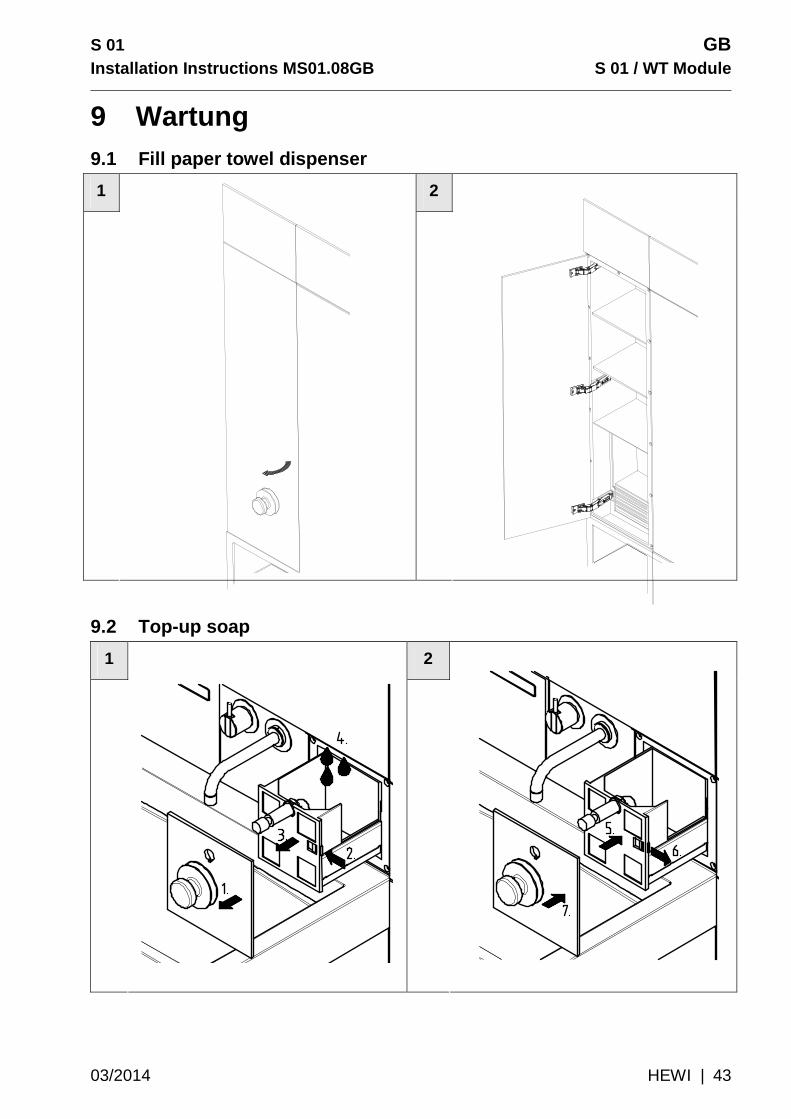
9 Wartung 9.1 Fill paper towel dispenser
1 2
9.2 Top-up soap
1 2
GB S 01
S 01 / WT Module Installation Instructions MS01.08G B
44 | HEWI 03/2014
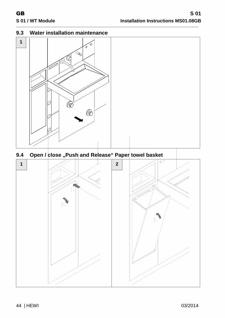
9.3 Water installation maintenance
1
9.4 Open / close „Push and Release“ Paper towel bas ket
1 2

S 01 GB Installation Instructions MS01.08GB S 01 / WT Modul e
03/2014 HEWI | 45
9.5 Remove „Push and Release“ Paper towel basket
1 2
9.6 Install „Push und Release“ Paper towel basket
1 2

GB S 01
S 01 / WT Module Installation Instructions MS01.08G B
46 | HEWI 03/2014
9.7 Open / close „non contact opening and closing“ paper basket
1 2
3 4

S 01 GB Installation Instructions MS01.08GB S 01 / WT Modul e
03/2014 HEWI | 47
9.8 Remove „non contact opening and closing“ paper towel basket
1 2. 3
4
GB S 01
S 01 / WT Module Installation Instructions MS01.08G B
48 | HEWI 03/2014
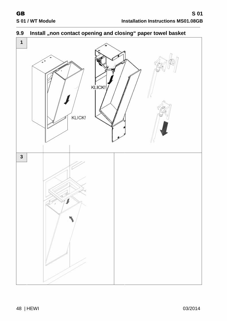
9.9 Install „non contact opening and closing“ paper towel basket
1
3
.
S 01 GB Installation Instructions MS01.08GB S 01 / WT Modul e
03/2014 HEWI | 49
10 Cleaning and maintenance CAUTION!
Material damage due to incorrect cleaning
Incorrect cleaning can cause attack and damage to the surfaces: � Do not use alkali, acidic or chlorine-containing cleaning
agents. � Do not use cleaning agents containing abrasive additives. � Do not use abrasive instruments, e.g. brushes. � Do not rub dry surfaces.
Plexiglas ® has a pore-free surface, to which dirt hardly sticks. Wipe down surfaces with water, a soft cloth or a sponge.
Use a standard commercial cleaning agent for thorough cleaning.
11 Disposal Electronic components
Electronic components must be disposed of in a communal collection point for hazardous electrical waste.
Product packaging The product packaging must be disposed of through the local household or paper waste collection facility.
GB S 01
S 01 / WT Module Installation Instructions MS01.08G B
50 | HEWI 03/2014
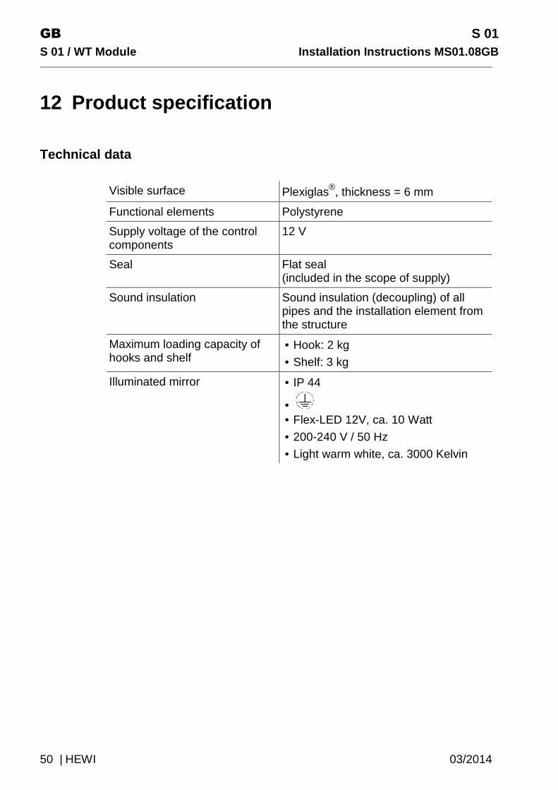
12 Product specification
Technical data
Visible surface Plexiglas®, thickness = 6 mm
Functional elements Polystyrene
Supply voltage of the control components
12 V
Seal Flat seal (included in the scope of supply)
Sound insulation Sound insulation (decoupling) of all pipes and the installation element from the structure
Maximum loading capacity of hooks and shelf
• Hook: 2 kg
• Shelf: 3 kg
Illuminated mirror • IP 44
• • Flex-LED 12V, ca. 10 Watt
• 200-240 V / 50 Hz
• Light warm white, ca. 3000 Kelvin
S 01 GB Installation Instructions MS01.08GB S 01 / WT Modul e
03/2014 HEWI | 51

MS01.08 14/03
Deutschland
HEWI Heinrich Wilke GmbH
Postfach 1260
D-34442 Bad Arolsen
Telefon: +49 5691 82-0
Telefax: +49 5691 82-319
www.hewi.dewww.hewi.com
Top Related