


Languages
Pages
Legal


Restriction/Classification
Cancelled
Restriction/Classification Cancelled
Restriction/Classification Cancelled
https://ntrs.nasa.gov/search.jsp?R=20090025409 2018-10-22T08:01:57+00:00Z
NATIONAL fDVISQRY COMMITTEE FQR AT3RONAUTICS
RESEARCH MEMORANDUM
FLOW COEFFICIENTS FOR ORIFICES I N BASE OF TRANSPIRATION-COOLED
TURBINE ROTOR BLADE
By Patrick L. Donoughe and Ernst I. Pras se
SUMMARY
Orifices i n the base of transpiration-coclled turbine blades are de- s i rable and necessary f o r properly dis t r ibut ing and regulating the flow t o the porous shel l . Because of differences i n or i f ice shape neither theore t ica l nor standard experimental flow coefficients f o r or i f ices or flow nozzles can be used fo r computing the pressure drop - flow relat ions. S ta t i c t e s t s on a segment of a transpiration-cooled turbine rotor blade with a wire-cloth she l l were therefore conducted t o determine the flow coefficients associated with some representative metering or i f ices ; average flow coefficients from 0.96 t o 0.79 were obtained fo r o r i f i ce ,
diameters from 0.031to 0.102 inch.
INTRODUCTION
I n the t ranspirat ion cooling of turbine blades, or i f ices i n the blade base t o meter the cooling a i r a l l ~ w a porous she l l of constant chordwise permeability t o be used and yet enable the proper chordwise coolant d is - t r ibut ion t o be obtained ( re fs . 1 and 2 ) . I n addition t o these desirable character is t ics , the or i f ice , by i t s flow and pressure drop relat ion, a l - so great ly diminishes the undesirable overcooling of a constant chordwise permeability s h e l l t ha t i s an otherwise necessary e v i l when the engine must operate over a range of a l t i t ude conditions ( r e f . 3).
Orifices i n the blade base serve t o d is t r ibute and t o regulate the amount of flow t o a par t icular compartment of the blade. It i s desirable t o take a large pressure drop across the or i f ice t o compensate f o r a l t i - tude ef fec ts , but t h i s drop should be commensurate with available cooling-air pressures. For a given flow through the porous she l l of the blade (which determines the heat transferred t o the blade) the required coolant-supply pressure i s dependent on the permeability character is t ics of the she l l and the flow coefficient of the metering o r i f i ce or flow nozzle. When the she l l permeability and or i f ice area a re specified, the required supply pressure varies inversely as the flow coefficient.
NACA RM E53WOa
Because of the many possible variations i n shape of the or i f ices used fn turbine blades compared with usual or i f ice shapes, standard values of the flow coefficient cannot be used a pr ior i . For metering or i f ices whose thickness i s different from tha t usually encountered, the flow coefficients varied from 0.78 t o 0.87 (ref . 2 ) .
I n the rotor blade reported i n reference 1, which used a wire-cloth she l l , the o r i f i ces i n the base were not i n the form of a plate . D i f - ferences i n flow coefficient due t o a change from a sintered t o a wire- c loth material would be expected t o be small but the differences resu l t - r
ing f romthe change i n shapes of the metering devices might be s ignif icant , r
To determine the flow coefficients associated with t h i s type of metering or i f ice , a segment of the rotor blade was bench tested and the r e su l t s are presented herein.
SYMBOLS
The following symbols are used i n t h i s report:
A f lowarea
B flow coefficient f o r or i f ice or flow nozzle
d flow diameter
g acceleration due t o gravi ty
hB pressure drop through o r i f i ce
p s t a t i c pressure
R gas constant
Re Reynolds number, wdn/&v
T temperature
v velocity out of porous sheet
W weight flow
p absolute viscosity
p density
Subscripts :
a cooling a i r or porous surface through which a i r i s passing
g gas (herein corresponds t o atmosphere)
n o r i f i ce (or flow nozzle)
o f o r reference temperature of 518.4' R
APPARATUS AND PROCEDURE
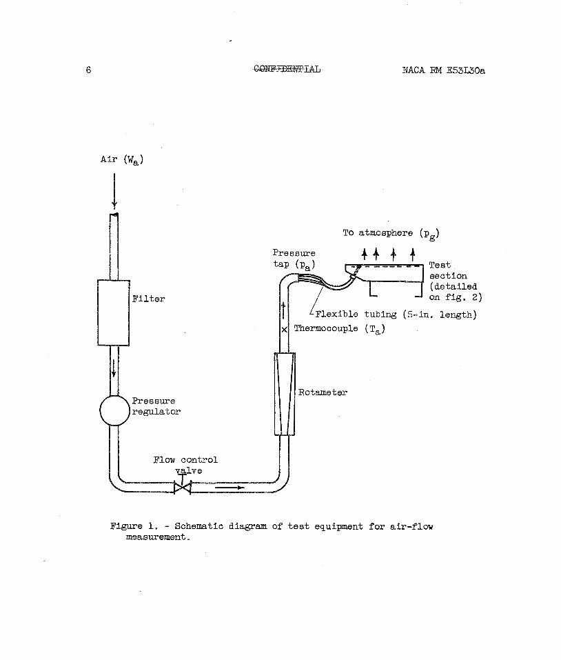
A schematic diagram of the t e s t equipment used fo r determining the pressure-drop character is t ics of the or i f ices i n ser ies with wire cloth i s shown i n figure 1. The present apparatus i s similar t o tha t described i n reference 4 except for some differences i n the upstream pressure s ta- t i o n and the t e s t section. The pressure tap shown i n f igure 1 i s i n a region where the maximum velocity i s l e s s than 40 f e e t per second, so t h a t it may be considered a t o t a l pressure.
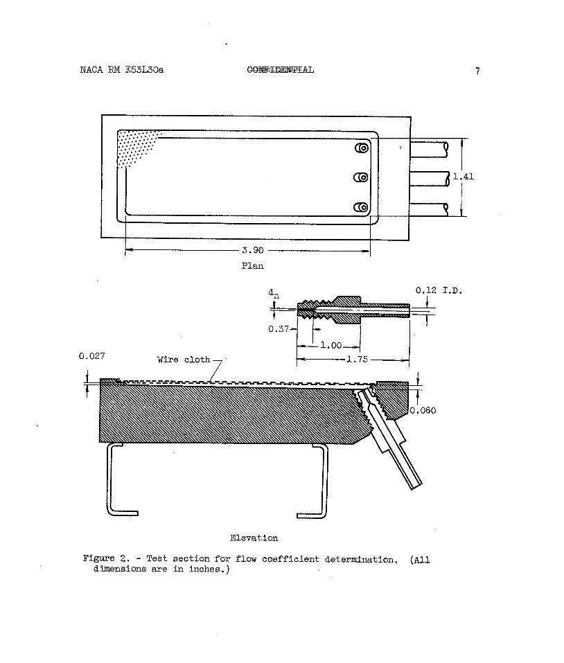
The t e s t section was an enlarged segment adapted from the transpiration-cooled blade reported i n reference 1 and i s shown i n f i g - ure 2. It consisted of a 20-by-200-mesh wire cloth calendered t o 0.0205- inch thickness and silver-soldered t o the brass frame containing three or i f ices. (permeability character is t ics of the cloth with t h i s thickness reduction (33.2 percent) are given i n re f . 5 and reproduced on f i g . 3.) The o r i f i ces were f i t t i n g s tha t simulated the air-flow-passage s ize i n the base of the aforementioned turbine blade and were made with exit-flow diameters of 0.031, 0.050, and 0.102 inch. A set consisting of three
i
or i f ices , a l l of the same size, were screwed in to the frame ( f ig . 2). After the f lex ib le tubing was attached t o the f i t t i n g s , a i r was passed through the apparatus.
CALCULATION METHOD
Because calculation of the flow coefficients from the measured data w a s desired, the equations re la t ing the weight flow of a i r and pressure drop are solved fo r the flow coefficient. These equations, given i n r e f - erences 2 and 3, then yield, f o r subsonic flow,
and, f o r supercr i t ical pressure drops (hg = 0.472 pa),
NACA RM E53L30a
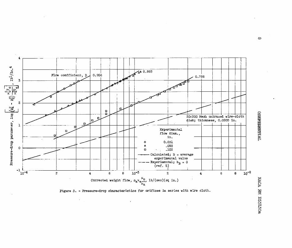
When the specif ic weight flow pava and the discharge pressure pg are
known, pa - hB can be obtained from the 20-by-200-mesh curve given i n
f igure 3. o or t h i s case the pa i n the ordinate i s actual ly pa - hB.) I
I I
Since pa i s measured, the pressure drop through the o r i f i ce or flow I
nozzle hg can be calculated.
RESULTS AND DISCUSSION
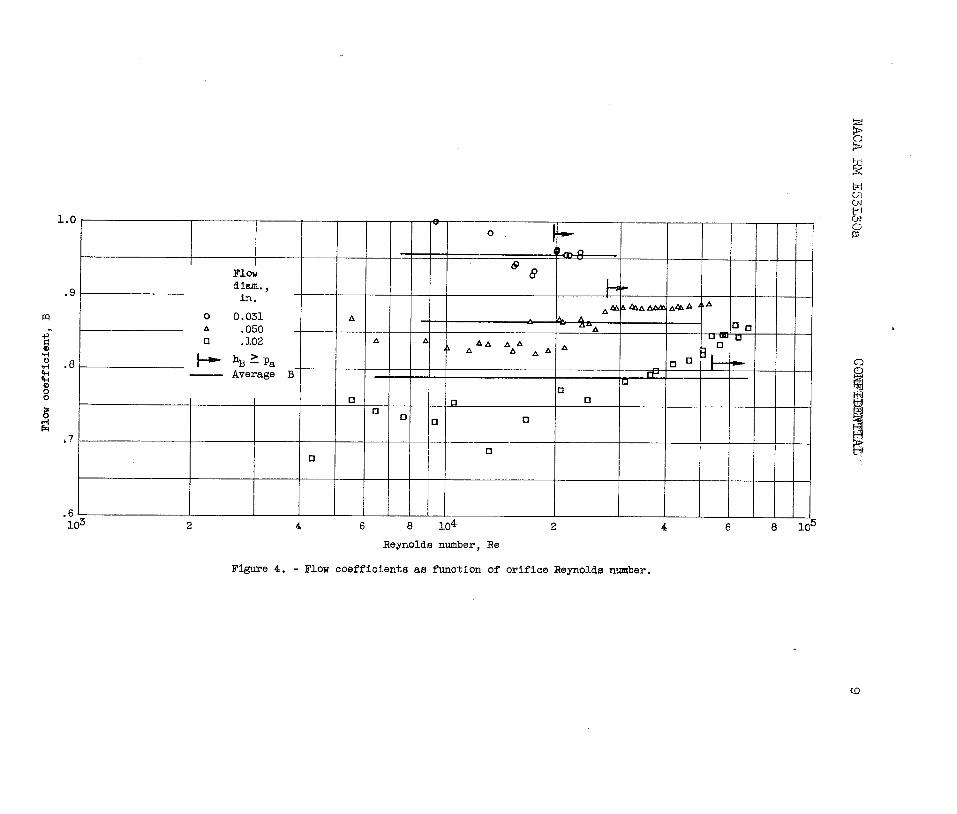
The experimental pressure-drop character is t ics for the simulated transpiration-cooled turbine rotor blade are given i n f igure 3. A s e t of data are shown f o r each o r i f i ce size. The average of the flow coef- f i c i e n t s f o r each o r i f i ce are 0.956, 0.865, and 0.788 f o r o r i f i ce diam- e t e r s of 0.031, 0.050, and 0.102 inch, respectively. The pseudo- analyt ical curves using experimental flow coefficients a re i n very good agreement f o r the two smaller or i f ices , indicating tha t the flow coeffi- cent i s effect ively constant over the range of weight flows invest i - gated. Greater variations between the calculated curve and the experi- mental data f o r the 0.102-inch-diameter o r i f i ce are indicated. The reason f o r t h i s discrepancy may be discerned with the a id of f igure 4,
In f igure 4, the flow coefficient B i s plot ted against the o r i f ice Reynolds number Re. (similar plo ts are used t o present data from standard or i f ices , e.g., r e f . 6, p. 60. ) The ve r t i ca l bars indi- cate the Reynolds number corresponding t o hB ,0.472pa, t ha t is , super-
c r i t i c a l pressure drops, For larger Reynolds numbers, the flow coeffi- cient i s essent ia l ly constant f o r a given o r i f i ce diameter. The average values of the flow coefficient f o r the two smaller or i f ices are not markedly different from the specif ic values. For the la rges t o r i f i ce (0.102-in. diameter.), however, the coefficient varies from 0.68 a t the low Reynolds number t o 0.86 f o r a Reynoids number greater than the value f o r supercr i t ica l pressure drop. This lmge variation i s probably due t o the diameter of the o r i f i ce belng almost as large a6 the 0.12-inch diameter of the f i t t i n g ( f ig . 2) and explains the discrepancies between calculated and experimental r e s u l t s noted on figure 3. With t h i s o r i f i ce diameter, the flow i s more akin t o pipe flow and, hence, the flow coeffi- c ient i s dependent on the Reynolds nunher f o r Reynolds numbers l e s s than c r i t i c a l . It may be note3 Eilst t the trend of flow coefficient with o r i f i ce s ize i s the same as t h a t i n reference 2.
Lewis Fl ight Propulsi'on Laboratory National Advisory Committee fo r Aeronautics
P l p ~ r p l n n A nhin n o ~ ~ m h a ~ . 1 1 1 OK?
NACA RM E53L30a
1. Donoughe, Pa t r i ck L., and Diaguila, Anthony J.: Exploratory Engine Test of Transpiration-Cooled Turbine-Rotor Blade with Wire-Cloth She l l . NACA RM E53K27, 1953.
2. Esgar, Jack B., and Richards, Hadley T. : Evaluation of E f e c t s of Random Permeability Variat ions on Transpiration-Cooled Surf aces. NACA RM E53G16, 1953.
3. Esgar, Jack B.: An Analytical Method f o r Evaluating Factors Affecting Application of Transpira t ion Cooling t o G a s Turbine Blades. NACA RM E52G01, 1952.
4. Eckert, E. R. G., Kinsler, Martin R . , and Cochran, Reeves P.: Wire Cloth a s Porous Material f o r Transpiration-Cooled Walls. NACA RM- E5lH23, 1951.
5. Donoughe, Pa t r i ck L., and MeKimon, Roy A. : Experimental Investiga- t i o n of Air-Flow Uniformity and Pressure Level on Wire Cloth f o r Transpiration-Cooling Applications. NACA RM E52E16, 1952.
6. Anon.: F lu id Meters, Their Theory and Application. Pa r t I. A.S.M.E. Res. Pub., Fourth ed. pub. by Am. Soc. Mech. Eng. (New York), 1937
NACA RM E53L30a
Figure 1, - Schematic diagram of test equipment for air-flow msasurement.
NACA RM E53L30a
Plan
Wire cloth 7
Elevation
Figure 2. - Test section for flow coefficient determination. (All dimensions are in inches. )
NA
CA RM
E53L30a
NACA RM E53L30a GW2Bw&&
FLOW COEFFICIENTS FOR ORIFICES I N BASE OF TRANSPIRA!TION-COOLED
TURBINE ROTOR BLADE
Pa t r i ck L. Donoughe ' Aeronautical Research S c i e n t i s t
Compressors and Turbines
Ernst I. Prasse Aeronautical Research S c i e n t i s t
Compressors and Turbines Approved :
Herman H. El lerbrock, Jr . ,,, Aeronautical Research s c i e n t i s t '
Compressors and Turbines
Robert 0 . Bullock Aeronautical Research S c i e n t i s t
Compressors and Turbines
, L ' . 4 Chief, Co~npressor and Turbine
Research Division
sks Dec. 11, 1953
COW IDENTIAL
NACA RM E53L30a
Turbine Cooling
Cooling - Gas-Turbine Systems
Donoughe, Patrick L., and Prasse, Ernst I.
Abstract
S t a t i c t e s t s on a segment of a transpiration-cooled turbine rotor blade with a wire-cloth she l l were conducted t o determine the flow coefficients associated with some representative metering or if ices . Average flow coefficients from 0.96 t o 0.79 were obtained fo r or i f ices of 0.031 t o 0.102 inch diameter.
Restriction/Classification Cancelled
Restriction/Classification Cancelled
Top Related