


Languages
Pages
Legal


Islamic University of Gaza Faculty
of Engineering
Civil Engineering Department
Report number: 1
Metacentric height of floating bodies
Prepared by: Waleed Kh. Abualtayef 120131025
Submitted to: Eng. Mohammed Mousa
Class No. : 103
Group No. : 2
Date: 9th-March-2015
2014-2015

Introduction:
The Stability of any vessel which is to float on water, such as a pontoon or ship, is of paramount importance. The theory behind the ability of this vessel to remain upright must be clearly understood at the design stage. Archimedes’ principle states that the buoyant force has a magnitude equal to the weight of the fluid displaced by the body and is directed vertically upward. Buoyant force is a force that results from a floating or submerged body in a fluid which results from different pressures on the top and bottom of the object and acts through the centroid of the displaced volume.
Objectives:
Determine the floatation characteristics for unloaded and for loaded pontoon.
And to determine the effect on floatation characteristics of altering the center of gravity of
the pontoon, with given total loading.
Apparatus:
1. Flat bottomed pontoon
2 . Hydraulic bench.

Procedures:
PART (1): Determination of floatation characteristic for unloaded and for loaded
pontoon.
1. Assemble the pontoon by positioning the bridge piece and mast i.e. locate the mast in the hole provided in the base of the vessel and clamp the bridge piece fixing screws into the locating holes in the sides of the vessel.
The 'plumb-bob' is attached to the mounting dowel located on the mast and is allowed to swing clear of and below the scale provided
2. Weigh the pontoon and determine the height of its center of gravity up the line of the mast by balancing the mast on a suitable knife edge support and measuring the distance from knife edge to outside base of pontoon.
3. Fill the hydraulic bench measuring tank, or other suitable vessel, with water and float the pontoon in it. Trim the balance of the pontoon by applying one of the small weights provided to the bridge piece at the required position so that the vessel floats without any list, this condition being indicated by the plumb-bob resting on the zero mark.
4. Apply a weight of 50g on the bridge piece loading pin then measure and record the angle of list and value of applied weight.
5. Take readings of list angle and applied weights (100, 150 & 200g). Repeat the procedure for lists in the opposite direction i.e. apply the weights to the opposite side of the bridge piece.
6. Calculate GM practically. Draw a relationship between θ (x-axis) and GM (y-axis), then obtain GM when θ equals zero.
7. Calculate GM theoretically.
8. Repeat the above procedures for increasing ballast loading conditions i.e. 2000 and 4000g.
PART (2): Determination of floatation characteristic when changing the center of
gravity of the pontoon.
1. Replace the large bilge weights by 4 50g weights.
2. Apply a weight of 300gm on a height of 190 mm from the pontoon surface.
3. Using the method of exercise A, determine the metacentric height 𝐺𝑀 (using applied weights 40, 80 &120g).
4. Move one 50g bilge weight to the mast head and once again determine 𝐺𝑀.
5. Repeat 100, 150 and 200g moved from the bilge weight to the mast head. Measure the position of the center of gravity from the base of the pontoon for each loading condition.
6. Determine the theoretical 𝐺𝑀 for each condition and also a height of a metacenter above water level.
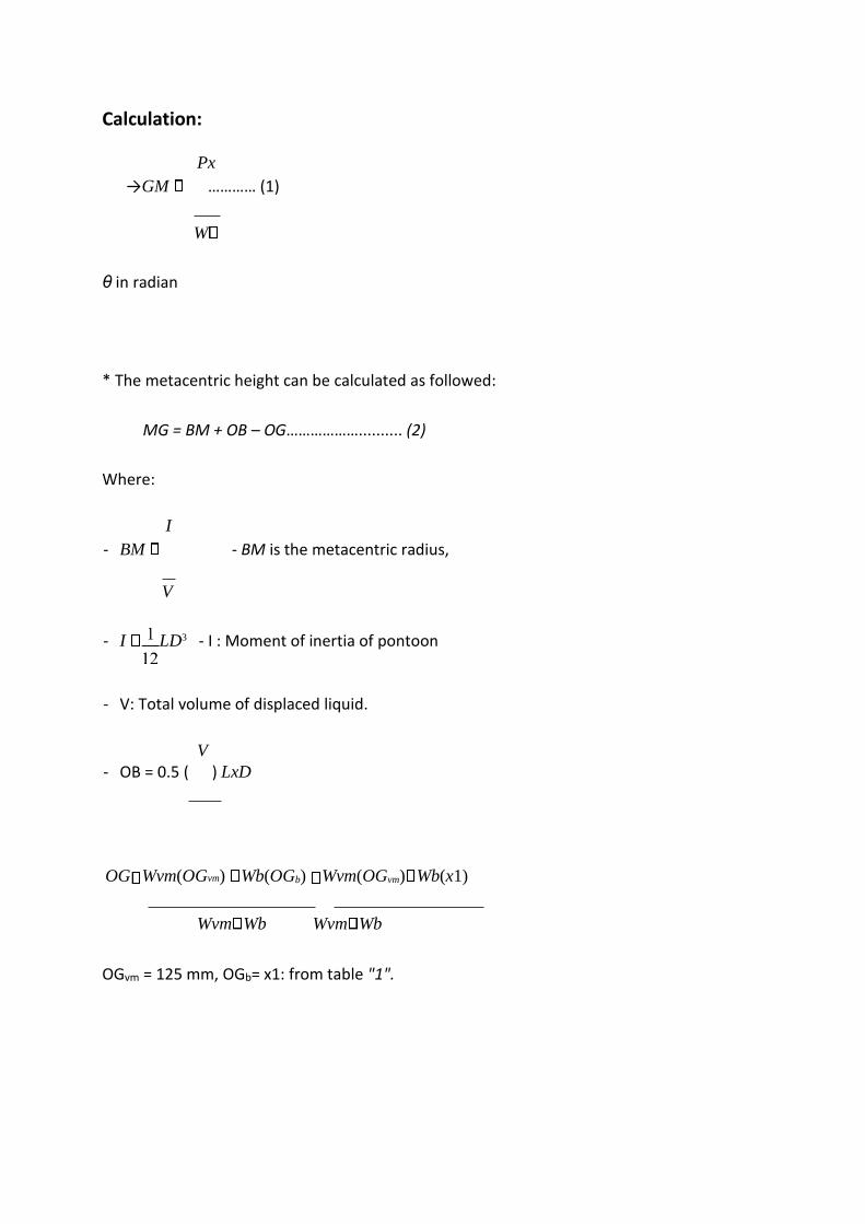
Calculation:
Px
→GM ………… (1)
W
θ in radian
* The metacentric height can be calculated as followed:
MG = BM + OB – OG……………….......... (2)
Where:
I
- BM - BM is the metacentric radius,
V
- I LD3 - I : Moment of inertia of pontoon
- V: Total volume of displaced liquid.
V - OB = 0.5 ( ) LxD
OG Wvm(OGvm) Wb(OGb) Wvm(OGvm) Wb(x1)
Wvm Wb Wvm Wb
OGvm = 125 mm, OGb= x1: from table "1".

Tables of results:
Table "1": Part(1)
GM @ zero
GM Th OG (mm)
OB (mm) BM(mm) Exp GM θ p W
38.94 55.72003
125 15.78947
164.9306
46.99745
2.5 50 3000
47.04222
5 100 3000
50.4638
8
7 150 3000
47.22192
10 200 3000
82.43 38.2741
2 87 26.3157
9 98.9583
3 35.2440
6 2 50 5000
28.22533
5 100 5000
32.59625
6.5 150 5000
31.45087
9 200 5000
43.2 32.5266
3 75 36.8421
1 70.6845
2 28.7827
2 3.5 100 7000
27.49954
5.5 150 7000
28.8365 7 200 7000
28.08113
9 250 7000
y = 0.954x + 38.94
y = -0.4178x + 34.229y = -0.057x + 28.656
0
10
20
30
40
50
60
0 5 10 15
Exp
. G
M (
mm
)
Angle(θ)

Table "2": Part(2)
M above water level
Theo GM
OG OB BM Exp GMfrom graph
Exp GM θ (degree)
Mast Weight =0.00
32.22682 2.5 40
122.948 34.36005 125.43 18.421 141.369 32.1 32.25753 5 80
32.30879 7.5 120
Mast Weight = 50
21.21068 3.8 40
122.948 23.43 136.36 18.421 141.369 21.34 22.12598 7.3 80
21.52195 11.3 120
Mast Weight= 100
16.11341 2.5 20
122.948 12.36 147.43 18.421 141.369 1584 12.41762 6.5 40
12.98944 12.5 80
Mast Weight =
150
6.714859 3 10
122.948 1.15 158.64 18.421 141.369 5.579 5.384798 7.5 20
8.985963 9 40
Unstable Mast Weight = 200

Comments:
When we increased θ,the value of GM is decreased.
y = 0.0164x + 32.182
y = 0.0369x + 21.344
y = -0.2802x + 15.848
y = 0.223x + 5.5793
0
5
10
15
20
25
30
35
0 2 4 6 8 10 12 14
Exp
. G
M(m
m)
θ (degree)
Wm=0
Wm=50
Wm=100
Wm=150
(Wm=50)خطي
(Wm=100)خطي
)Wm=150)خطي
)Wm=150)خطي
Top Related