


Languages
Pages
Legal


HOT WORK TOOL STEEL
RAVNEX DC
The nameyou cantrust

C O N T E N T S GENERAL CHARACTERISTICS 02Chemical composition
Application
Microstructure in delivered condition
Toughness
Qualitative comparison
PHYSICAL PROPERTIES 05
MECHANICAL PROPERTIES 06Impact toughness at elevated temperatures
CONTINIOUS COOLING CURVES-CCT 07
HEAT TREATMENT 08Annealing
Stress relieving
Hardening
Tempering
Dimensional changes during hardening
and tempering
SURFACE TREATMENT 10Nitriding and nitrocarburising
WELDING AND EDM 11Welding
Electrical discharge machining
RECOMMENDATIONS FOR MACHINING 12
CASE STUDY 13
RAVNEX DC

CHEMICAL COMPOSITION (%)
GENERAL CHARACTERISTICS
M E T A L R A V N E • T h e n a m e y o u c a n t r u s t
Chemical element content is in wt.%
02
RAVNEX DC is a supreme hot-work tool steel
produced in METAL RAVNE, known for:
• High impact toughness
• High hot tensile properties and high working hardness
• High thermal conductivity
• Good polishability
• Nitrability
• High cleanliness
• Longer tool life
• Excellent homogeneity
• Weldability
METAL AISI W .Nr . C Si Mn Cr Mo V
RAVNEX DC H11 mod ~1.2343 0.36 0.20 0.30 5.00 1.35 0.45
APPLICATION
RAVNEX DC is primarily designed for die casting of light metals and alloys. It is often used for highly stressedhot-work structural parts where superior toughness is required (up to average Charpy V-notch value of 29.8 Jouleat 44-46 HRC according to NADCA#207).
RAVNEX DC is also recommended for die forging and extrusion. Because of its good polishability,the grade can be used for plastic molding applications and processing of glass.
RAVNEX DC is supplied in annealed condition, max. 209 HBW (705 N/mm2).

T h e n a m e y o u c a n t r u s t • M E T A L R A V N E
> TAB 2: ACCEPTABILITY CRITERIA OF ANNEALED MICROSTRUCTURE ACCORDING TO NADCA #207-2003
MICROSTRUCTURE IN DELIVERED CONDITION
RAVNEX DC is inspected in soft annealed condition according to SEP 1614 (Stahl-Eisen-PrüfblattSEP 1614 - September 1996), and according to NADCA#207 standard.
Cleanliness according to DIN 50602 is K1≤10.
> TAB 1: MICROHOMOGENEITY
50xIncreasing Degree of Segregation
Increasing Reduction R
atio
500x
Premium quality Standard quality Not acceptable
All microstructures etched with 5% NitalAcceptable Unacceptable
SA SB SC SD SE
03
RAVNEX DCannealed
Accepted rating charts of annealed RAVNEX DC.

M E T A L R A V N E • T h e n a m e y o u c a n t r u s t
QUALITATIVE COMPARISON
RAVNEX DC is a premium tool steel of highest toughness produced in Metal Ravne.Chart shows its toughness at high temperature compared to 1.2343 and conventional W.Nr1.2344 hot-work tool steel.
TOUGHNESS
Un-notched specimens (7 x 10 x 55 mm3) are used to test impact toughness in transverse direction,SEP 1314 (Stahl-Eisen-Prüfblatt SEP 1314- April 1990). Specimens are quenched and tempered to 45 +/- 2 HRC,and test is performed at 20 °C.
Average impact toughness of forged quality is higher than 299 Joule for average forging size of 900 x 400 mm.
DGM (Deutsche Gesellschaft fürMaterialkunde) recommendsimpact toughness of minimum250 Joules for hot-work tool steelin various hot-work applications.
STRENGTH means ultimatetensile strength derived from anengineering stress-strain curve.
TOUGHNESS is estimated byreduction in cross-section areaof tensile test probe at rupture.
RS GRADE STRENGTH TOUGHNESS
400
300
200
100
0
Impa
ct t
oug
hnes
s (J
oul
e)
44-46 HRC
DGMW.Nr. 1.2343
RAVNEX DC
04
W.Nr.1.2343
W.Nr.1.2344
RAVNEX DC

T h e n a m e y o u c a n t r u s t • M E T A L R A V N E
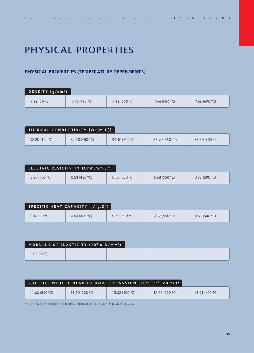
PHYSICAL PROPERTIES
D E N S I T Y ( g / c m 3 )
PHYSICAL PROPERTIES (TEMPERATURE DEPENDENTS)
* CTE is the mean coefficient of thermal expansion with reference temperature of 20 °C.
T H E R M A L C O N D U C T I V I T Y ( W / ( m . K ) )
E L E C T R I C R E S I S T I V I T Y ( O h m . m m 2 / m )
S P E C I F I C H E A T C A P A C I T Y ( J / ( g . K ) )
M O D U L U S O F E L A S T I C I T Y ( 1 0 3 x N / m m 2 )
C O E F F I C I E N T O F L I N E A R T H E R M A L E X P A N S I O N ( 1 0 - 6 ° C - 1 , 2 0 ° C ) *
7.85 (20 °C) 7.80 (450 °C) 7.69 (500 °C) 7.67 (550 °C) 7.65 (600 °C)
28.40 (100 °C) 30.1 (450 °C) 30 (500 °C) 29.90 (550 °C) 29.70 (600 °C)
0.50 (20 °C) 0.68 (450 °C) 0.86 (500 °C) 0.90 (550 °C) 0.96 (600 °C)
0.46 (20 °C) 0.51 (450 °C) 0.55 (500 °C) 0.57 (550 °C) 0.59 (600 °C)
12.40 (200 °C) 12.80 (300 °C) 13.20 (400 °C) 13.60 (500°C) 14.20 (600 °C)
05
215 (20 °C) 185 (450 °C) 176 (500 °C) 171 (550 °C) 165 (600 °C)

Impa
ct t
oug
hnes
s K
V (
Joul
e)
90
80
70
60
50
40
0
Testing temperature (° C)
M E T A L R A V N E • T h e n a m e y o u c a n t r u s t
MECHANICAL PROPERTIES
IMPACT TOUGHNESS AT ELEVATED TEMPERATURES
Figure shows impact toughness as function of temperature.Samples are taken from the core of a forged block in short transverse direction.They are quenched and tempered (Q+T; 1000 °C / oil / 2x tempering) to 45 +/- 1 HRC.Measurement: EN ISO 148: 2010
200 250 300 350 400 450 500 550 600
06
15010050

CONTINIOUS COOLING CURVES-CCT
Legend:A - AusteniteK - CarbideP - PerliteM - MartensiteB - Bainite
Austenitising temperature: 990 °C; soak time: 15 min
1200
1100
1000
900
800
700
600
500
400
300
200
100
0
Te
mp
era
ture
(°C
)
A + K
M + K
Ms
1 10
100
1 000 10 000 100 000
Seconds
TIME 101 1000
Minutes
100
B + K
Ac3 = 880 °C
P + K
QUENCH RATE SHOULD BE SUFFICIENT TO FORM PREDOMINANTLY MARTENSITIC STRUCTUREWITHOUT SIGNIFICANT AMOUNT OF BAINITE. SIGNIFICANT AMOUNT OF BAINITE FAVOURSTHERMAL FATIGUE AS A LESS STABLE PHASE CONSTITUENT WITH LOWER STRENGTH.
TIP 1
07
T h e n a m e y o u c a n t r u s t • M E T A L R A V N E
576 517 461
Ac1 = 805 °C
2,9 °C/s 0,2 °C/s 0,043 °C/s
Hardness HV0.3
1 10Hours
2 20

A N N E A L I N G
HEAT TREATMENT
FOR APPLICATIONS EXPOSED TO EXTREME THERMAL LOADING A PROPER HEAT TREATMENTIS ESSENTIAL. TO PREVENT EXCESSIVE GRAIN GROWTH DURING AUSTENITIZATION IT ISPREFERABLE TO LEAVE SOME OF THE CARBIDES NOT DISSOLVED.
TIP 2
Recommendations or NADCA#207.
HEATING
50 °C/h
Protect against oxidation, scaling anddecarburisation.
ANNEALING TEMPERATURE
800 - 850 °C
Min. 4 hours.
COOLING
20 °C/h
Slow in furnace. From 600 °C aircooling is possible.
S T R E S S R E L I E V I N G
HEATING
100 °C/h
STRESS RELIEVING
600 °C - 650 °C or 50 °C under thelast tempering temperature.
Min. 3 hours.
COOLING
20 °C/h
Slow and uniformly in the furnace toprevent formation of additionalresidual stresses. From approximately200 °C air cooling is possible.
Protect against oxidationand decarburisation.
H A R D E N I N G Hardness after hardening is 50-54 HRC (1680 - 1916 N/mm2).
HEATING AUSTENITISING COOLING
980 - 1000 °C See CCT diagram25 - 650 °C, 150 - 220 °C/h650 - 850 °C, ≤150 °C/h,850 - 1000 °C, ≤150 °C/h
Fast cooling is recommended inpressurized N2. For large dimensionhot-work tooling see NADCA#207 orGM DC-9999-1Rev.18 specification.
Hold in furnace atT = 650 °C / 850 °Cuntil TSURFACE-TCORE ≤≤110 °C / 60 °C
TSURFACE is measured at 15mmunderneath surface, maximum soaktime is 30 min.
08
M E T A L R A V N E • T h e n a m e y o u c a n t r u s t

T h e n a m e y o u c a n t r u s t • M E T A L R A V N E
INCREASED TOUGHNESS OF THIS SPECIAL GRADE OFFERS ONE TO SELECT HIGHER WORKINGHARDNESS. HIGHER THERMAL CONDUCTIVITY AND HIGH TEMPERATURE STRENGTH COMPAREDTO H11 GRADE ALSO CONTRIBUTE TO ITS IMPROVED RESISTANCE TO THERMAL FATIGUE.
TIP 3
DIMENSIONAL CHANGES DURING HARDENING AND TEMPERING
It is recommended to leave machining allowance before hardening of minimum 0.2 % of dimension,equal in all three directions.
TEMPERING
Tempering must start immediately after completion of quenching (when part reaches 90-70 °C).Three tempering treatments are recommended. First tempering destabilizes retained austenite.Second tempering tempers newly formed microstructure constituents.
HEATING TEMPERING TEMPERATURE COOLING
1st: 520 - 530 °C2nd: choose working hardness (see tempering diagram).3rd: 50 °C bellow 2nd tempering.
Cool in air or in the furnace toroom temperature betweentempering cycles.
150 °C/h - 250 °C/h
1 hour per 25mm wall thicknessbased on the furnace temperature.Minimum 2 hours.
Protect against oxidationand decarburisation.
Ha
rdn
ess
(H
RC
)
60
55
50
45
40
200 300 400 500 600 700
Tempering temperature (°C)
Ha
rdn
ess
(H
RC
)
60
55
50
45
40
500 600 700
Tempering temperature (°C)
09
550 650
25 mm/oil25 mm/oil

M E T A L R A V N E • T h e n a m e y o u c a n t r u s t
NITRIDING AND NITROCARBURISING
Nitriding treatment is commonly recommended to enhance surface properties of RAVNEX DC.
Nitriding treatment for hot-work applications is performed by producing diffusion zone only ( nitriding phase) of a depthdetermined by particular application requirements, and completely inhibit surface compound layer ( and nitriding phases).
Nitriding treatment for plastic-molding or cold-work applications with wear resistance requirements is performed byproducing surface compound layer of composition and thickness determined by particular application requirements.
For applications with requirement for additional surface protection, improvement of sliding properties, or improvementof corrosion resistance, it is recommended that oxidation treatment (Fe3O4) follows the nitriding.
For details on surface preparation and setup of nitriding treatment parameters to obtain required surface propertiesplease consult our approved nitriding specialist.
SURFACE TREATMENT
Te
mp
era
ture
(°C
)
0
Nitriding potential
0.1 1 10
800
700
600
500
400
300
10
Lehrer diagram presented in figure shows the effect of two parameters:(1) nitriding potential (a function of partial pressure of ammonia and hydrogen), and (2) temperature, on composition ofnitriding phases formed on material surface. Figure shows recommended selection of the two governing parameters forappropriate execution of nitriding for two extreme application regimes, hot work on one hand, and cold-work on the other.
Nitriding of hot-work applications (limited or no compound layer)
Nitriding of cold-work applications (well developed compound layer)
Nitriding for intermediate surface properties

WELDING
RAVNEX DC is a readily weldable alloy by TIG or MMA welding processes in hardened or soft-annealed condition. Fillermetal should be of the same or similar chemical composition.
Heat treatment after welding is recommended. Annealing should be performed after welding of soft annealed parts, whereastempering at temperature of about 50 °C below tempering temperature should be performed after welding of hardenedand tempered parts. Laser welding is recommended for repair of smaller cracks and edges.
WELDING AND EDM
ELECTRICAL DISCHARGE MACHINING
Electrical discharge machining (EDM) leaves a brittle surface layer due to melting and resolidification of surface material.
It is recommended to: (1) remove the resolidified layer by polishing, grinding or other mechanical methods,and (2) temper the work-piece at temperature of about 50 °C below the tempering temperature.Execution of tempering of re-hardened and jet untempered layer underneath the surface is critical.
PREHEATING TEMPERATURE
320 - 350 °C
MAXIMUM INTERPASS TEMPERATURE
470 °C
POST WELD COOLING
Approximately 30 °C / h to notless than 70 °C, then tempering.
WELDING METHOD
TIG, MMA
FILLER MATERIAL
H11
HARDNESS AFTER WELDING
~ 50 HRC
11
T h e n a m e y o u c a n t r u s t • M E T A L R A V N E

M E T A L R A V N E • T h e n a m e y o u c a n t r u s t
The information below is provided solely as a general machining guideline. It refers to material soft annealed condition.
RECOMENDATIONS FOR MACHINING
D R I L L I N G
INSERT DRILL DIAMETER (mm) CUTTING SPEED (m/min) FEED (mm/rev)
F A C E M I L L I N G
INSERT CUTTING SPEED (m/min) FEED (mm/tooth) DEPTH OF CUT (mm)
T U R N I N G
* c. = coated carbide
INSERT CUTTING SPEED (m/min) FEED (mm/rev) DEPTH OF CUT (mm)
12
P20-P30 c.* (rough turning) 180 - 220 0.20 - 0.40 2.00 - 4.00
P10 c.* (fine turning) 230 - 270 0.05 - 0.20 0.50 - 2.00
HSS (fine turning) 25 - 30 -0.30 -2.00
HSS 5 - 20 15 - 20 0.05 - 0.30
Coated HSS 5 - 20 35 - 40 0.05 - 0.30
P20-P40 c.* (rough milling) 150 - 220 0.20 - 0.40 2.00 - 4.00
P10 c.* (fine milling) 230 - 260 0.10 - 0.20 -2.00

CASE STUDY
HEAT TREATMENT OF RAVNEX DC
Control of quenching is critical to assure dimension stability, optimum microstructure and mechanical properties of anywork-piece.
Finite element modelling of heat treatment reveals that both hardening temperature and soaking time, as well as quenchingrate strongly depend on work piece size and geometry.
Figure 1 shows temperature distribution intwo workpieces of different thickness ata given time (t), (see Figure 2) duringquenching. One can observe a hot core and ahigh temperature gradient in a thick workpiece,while a thin workpiece has at same coolingtime almost uniform temperature distribution.
13
> FIG 1
T h e n a m e y o u c a n t r u s t • M E T A L R A V N E

M E T A L R A V N E • T h e n a m e y o u c a n t r u s t
Tem
pera
ture
(°C
)
0
Time (min)
10 20 30 40 50 60
> FIG 2
t
1100
T
900
800
700
600
500
400
300
200
100
0
A1
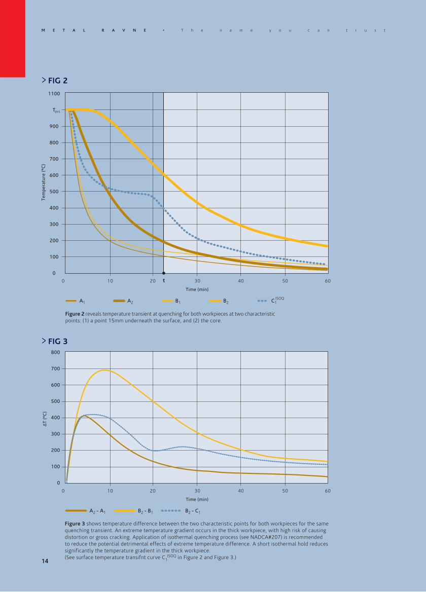
Figure 2 reveals temperature transient at quenching for both workpieces at two characteristic points:(1) a point 15mm underneath the surface, and (2) the core.
Figure 3 shows temperature difference between the two characteristic points for both workpieces for the samequenching transient. An extreme temperature gradient occurs in the thick workpiece, with high risk of causingdistortion or gross cracking. Application of isothermal quenching process (see NADCA#207) is recommendedto reduce the potential detrimental effects of extreme temperature difference. A short isothermal hold reducessignificantly the temperature gradient in the thick workpiece. (See surface temperature transifnt curveC1
ISO-Q in Figure 2 and Figure 3.)
A2 B1 B2 C1ISO-Q
0
Time (min)
10 20 30 40 50 60
> FIG 3800
700
600
500
400
300
200
100
0
A2 - A1
T (°
C)
B2 - B1 B2 - C1
14
ISO-Q

Figure 4 shows average cooling speed between 800 and 500 °C at the core of a generalized geometry workpiece. Both geometry and size of theworkpiece is defined by its volume (V) to surface (S) ratio. Medium quenching power in a vacuum-type furnace is applied to determine the workpiececooling speed (6 bar N2 overpressure with medium to high gas circulation). The plot is particularly useful for determining optimum quenchingspeed in workpieces where temperature at core is not possible to directly monitor by thermocouple.SURFACE - temperature at a point 15 mm underneath the center of largest workpiece surface.CORNER* - temperature at a point 15 mm underneath the most exposed part of workpiece.
* data presented are computed for a point 15mm underneath an angle of a cube.
SHARP EDGES ON THE TOOL IN HEAT TREATMENT SHOULD BE AVOIDED TO PREVENT GROSS CRACKINGOR MICRO QUENCHING CRACKS WHICH CAN LEAD TO FORMATION OF LEADING CRACKS.TIP 4
To achieve optimum material properties, heat treatment parameters should be adjusted to specific workpiece size andgeometry. Critical quench rate is needed to avoid both pearlite formation and carbide precipitation.
In order to run quenching of a particular dimension and geometry workpiece at optimum velocity it is critical to continuouslymonitor temperature of both the surface and the core throughout the cycle.
> FIG 4
Co
olin
g ve
loci
ty (
°C/m
in)
20
V/A (mm)
30
300
250
200
150
100
50
0
CORE SURFACE CORNER
40 50 60 70 80 90 100 110 120
15
T h e n a m e y o u c a n t r u s t • M E T A L R A V N E

M E T A L R A V N E • T h e n a m e y o u c a n t r u s t
16
Notes

Publisher: Ravne Steel Center • Text: Metal Ravne • Production: RD BORGIS • AD/D: XLMS • Photos: archive Metal Ravne • Print: ALE d.o.o. • June 2014
METAL RAVNE, d.o.o.Koroπka cesta 14, 2390 Ravne na Koroπkem, Slovenia
Telephone: +386 2 870 7000, Telefax: +386 2 870 7006E-mail: [email protected]
www.metalravne.com
RAVNEX HD is produced by:
RAVNEX HD is distributed by:

HOT WORK TOOL STEEL
RAVNEX HD
The nameyou cantrust


RAVNEX HDC O N T E N T S GENERAL CHARACTERISTICS 02
Chemical composition
Application
Microstructure in delivered condition
Toughness
Qualitative comparison
PHYSICAL PROPERTIES 05
CONTINIOUS COOLING CURVES-CCT 06
HEAT TREATMENT 07Annealing
Stress relieving
Hardening
Tempering
Dimensional changes during hardening
and tempering
HARDNESS 09
MECHANICAL PROPERTIES 09Impact toughness at elevated temperatures
SURFACE TREATMENT 10Nitriding and nitrocarburising
WELDING AND EDM 11Welding
Electrical discharge machining
RECOMMENDATIONS FOR MACHINING 12
CASE STUDY 13Heat treatment of RAVNEX HD RS 450

CHEMICAL COMPOSITION (%)
Controlled chemical composition with minimal content of detrimental elements compared to standard steel grades.
GENERAL CHARACTERISTICS
M E T A L R A V N E • T h e n a m e y o u c a n t r u s t
RAVNEX HD is a supreme hot-work tool steelproduced in METAL RAVNE, known for:
• Excellent impact toughness
• High hot tensile properties and high working hardness
• Excellent thermal conductivity
• Good polishability
• Excellent hardenability
• Nitrability
• High cleanliness
• Longer tool life
• Excellent homogeneity
• Weldability
APPLICATION
RAVNEX HD is primarily designed for die casting of light metals and alloys. Due to its excellent hardenabilityit is especially recommended for high-dimension tooling. It is often used for highly stressed hot-work structural partswhere superior toughness is required.
RAVNEX HD is also recommended for die forging and extrusion. Because of its good polishability, the gradecan be used for plastic molding applications and processing of glass.
RAVNEX HD is supplied in annealed condition, max. 235 HBW (791 N/mm2).
Chemical element content is in wt.%
METAL AISI W .Nr . C Si Mn Cr Mo V Ni
RAVNEX HD - - 0.37 0.25 0.43 4.90 1.60 0.59 1.60
02

T h e n a m e y o u c a n t r u s t • M E T A L R A V N E
> TAB 2: ACCEPTABILITY CRITERIA OF ANNEALED MICROSTRUCTURE ACCORDING TO NADCA #207-2003
MICROSTRUCTURE IN DELIVERED CONDITION
RAVNEX HD is inspected in soft annealed condition according to SEP 1614 (Stahl-Eisen-Prüfblatt SEP 1614 - September1996), and according to NADCA#207 standard.
Cleanliness according to DIN 50602 is K1≤10.
> TAB 1: MICROHOMOGENEITY
Accepted rating charts of annealed RAVNEX HD.
50xIncreasing Degree of Segregation
Incr
easi
ng R
educ
tio
n R
atio
500x
Premium quality Standard quality Not acceptable
All microstructures etched with 5% NitalAcceptable Unacceptable
SA SB SC SD SE
03
RAVNEX HDannealed

M E T A L R A V N E • T h e n a m e y o u c a n t r u s t
QUALITATIVE COMPARISON
RAVNEX HD is a premium tool steel of highest toughness produced in Metal Ravne. Chart shows its impact toughnesscompared to W.Nr1.2343, conventional W.Nr1.2344 hot-work tool steel and to RAVNEX DC.
TOUGHNESS
Un-notched specimens (7 x 10 x 55 mm) are used to test impact toughness in transverse direction, SEP 1314(Stahl-Eisen-Prüfblatt SEP 1314- April 1990). Specimens are quenched and tempered to 45 +/- 2 HRC, and testis performed at 20°C.
Average impact toughness of forged quality is higher than 299 Joule for average forging size of 900 x 400 mm.
DGM (Deutsche Gesellschaft fürMaterialkunde) recommendsimpact toughness of minimum250 Joules for hot-work tool steelin various hot-work applications.
STRENGTH means ultimatetensile strength derived from anengineering stress-strain curve.
RS GRADE STRENGTH TOUGHNESS
400
300
200
100
0
Impa
ct t
oug
hnes
s (J
oul
e)
44-46 HRC
DGMW.Nr. 1.2343
RAVNEX HD
W.Nr.1.2343
W.Nr.1.2344
RAVNEX DC
RAVNEX HD
04
T h e n a m e y o u c a n t r u s t • M E T A L R A V N E
PHYSICAL PROPERTIES
D E N S I T Y ( g / c m 3 )
PHYSICAL PROPERTIES (TEMPERATURE DEPENDENTS)
* CTE is the mean coefficient of thermal expansion with reference temperature of 20 °C.
T H E R M A L C O N D U C T I V I T Y ( W / ( m . K ) )
E L E C T R I C R E S I S T I V I T Y ( O h m . m m 2 / m )
S P E C I F I C H E A T C A P A C I T Y ( J / ( g . K ) )
M O D U L U S O F E L A S T I C I T Y ( 1 0 3 x N / m m 2 )
C O E F F I C I E N T O F L I N E A R T H E R M A L E X P A N S I O N ( 1 0 - 6 ° C - 1 , 2 0 ° C ) *
7.83 (20 °C) 7.70 (450 °C) 7.68 (500 °C) 7.66 (550 °C) 7.65 (600 °C)
32.80 (100 °C) 34.30 (450 °C) 34.10 (500 °C) 33.90 (550 °C) 33.50 (600 °C)
0.50 (100 °C) 0.58 (450 °C) 0.63 (500 °C) 0.68 (550 °C) 0.73 (600 °C)
0.44 (20 °C) 0.64 (450 °C) 0.68 (500 °C) 0.72 (550 °C) 0.83 (600 °C)
210 (20 °C)
11.60 (200 °C) 11.80 (300 °C) 12.02 (400 °C) 12.04 (500 °C) 12.01 (600 °C)
05

M E T A L R A V N E • T h e n a m e y o u c a n t r u s t
CONTINIOUS COOLING CUR VES-CCT
Legend:A - AusteniteK - CarbideP - PerliteM - MartensiteB - Bainite
Austenitising temperature: 1030 °C; soak time: 15 min
1200
1100
1000
900
800
700
600
500
400
300
200
100
0
Te
mp
era
ture
(°C
)
A + K
M + K
Ms
1 10
100
1 000 10 000 100 000Seconds
TIME 101 1000Minutes
100
B + K
1 000 000
Ac3 880 °C
Hardness HV10 161453479633655685
P + K
QUENCH RATE SHOULD BE SUFFICIENT TO FORM PREDOMINANTLY MARTENSITIC STRUCTUREWITHOUT SIGNIFICANT AMOUNT OF BAINITE. SIGNIFICANT AMOUNT OF BAINITE FAVOURSTHERMAL FATIGUE AS A LESS STABLE PHASE CONSTITUENT WITH LOWER STRENGTH.
TIP 1
06
Ac1 790 °C

A N N E A L I N G
T h e n a m e y o u c a n t r u s t • M E T A L R A V N E
HEAT TREATMENT
FOR APPLICATIONS EXPOSED TO EXTREME THERMAL LOADING A PROPER HEAT TREATMENTIS ESSENTIAL. TO PREVENT EXCESSIVE GRAIN GROWTH DURING AUSTENITIZATION IT ISPREFERABLE TO LEAVE SOME OF THE CARBIDES NOT DISSOLVED.
TIP 2
Recommendations or NADCA#207.
HEATING
50 °C/h
Protect against oxidation, scaling anddecarburisation.
ANNEALING TEMPERATURE
800 - 850 °C
Min. 4 hours.
COOLING
20 °C/h
Slow in furnace. From 600 °C aircooling is possible.
S T R E S S R E L I E V I N G
HEATING
100 °C/h
STRESS RELIEVING
650 °C or 50 °C under the lasttempering temperature.
Min. 3 hours.
COOLING
20 °C/h
Slow and uniformly in the furnace toprevent formation of additionalresidual stresses. From approximately200 °C air cooling is possible.
Protect against oxidationand decarburisation.
H A R D E N I N G Hardness after hardening is 56-58 HRC (2030 - 2180 N/mm2).
HEATING AUSTENITISING COOLING
1030 - 1050 °C See CCT diagram25 - 650 °C, 150 - 220 °C/h650 - 850 °C, ≤150 °C/h,850 - 1030 °C, ≤150 °C/h
Fast cooling is recommended inpressurized N2. For large dimensionhot-work tooling see NADCA#207 orGM DC-9999-1Rev.18 specification.
Hold in furnace atT = 650 °C / 850 °Cuntil TSURFACE-TCORE ≤≤110 °C / 60 °C
TSURFACE is measured at 15mmunderneath surface, maximum soaktime is 30 min.
07

M E T A L R A V N E • T h e n a m e y o u c a n t r u s t
INCREASED TOUGHNESS OF THIS SPECIAL GRADE OFFERS ONE TO SELECT HIGHER WORKINGHARDNESS. HIGHER THERMAL CONDUCTIVITY AND HIGH TEMPERATURE STRENGTH COMPAREDTO H11 GRADE ALSO CONTRIBUTE TO ITS IMPROVED RESISTANCE TO THERMAL FATIGUE.
TIP 3
DIMENSIONAL CHANGES DURING HARDENING AND TEMPERING
It is recommended to leave machining allowance before hardening of minimum 0.2 % of dimension,equal in all three directions.
TEMPERING
Tempering must start immediately after completion of quenching (when part reaches 90-70 °C). Three tempering treatmentsare recommended. First tempering destabilizes retained austenite. Second tempering tempers newly formed microstructureconstituents.
HEATING TEMPERING TEMPERATURE COOLING
1st: 540 - 550 °C2nd: choose working hardness (see tempering diagram).3rd: 50 °C bellow 2nd tempering.
Cool in air or in the furnace toroom temperature betweentempering cycles.
150 °C/h - 250 °C/h
1 hour per 25mm wall thicknessbased on the furnace temperature.Minimum 2 hours.
Protect against oxidationand decarburisation.
Ha
rdn
ess
(H
RC
)
60
55
50
45
40
100 200 300 400 500 600 700
Tempering temperature (°C)
T austenization = 1030 °C
T austenization = 1050 °C
Ha
rdn
ess
(H
RC
)
60
55
50
45
40
550 600 650
Tempering temperature (°C)
08
25 mm/oil25 mm/oil

Ha
rdn
ess
(H
RC
)
60
55
50
45
40
35
480
Tempering temperature (°C)
T h e n a m e y o u c a n t r u s t • M E T A L R A V N E
HARDNESS
500 520 540 560 580 600 620 640 660
1050 / 1x 2h
1050 / 2x 2h
09
MECHANICAL PROPERTIESIMPACT TOUGHNESS AT ELEVATED TEMPERATURES
TEMPERING DIAGRAM RAVNEX HD
Impa
ct t
oug
hnes
s K
V (
Joul
e)
90
80
70
60
50
40
30
0
Tempering temperature (°C)
100 200 300 400 500
Figure shows impact toughness as function of temperature.Samples are taken from the core of a forged block in short transverse direction.They are quenched and tempered (Q+T; 1030 °C / oil / 2x tempering) to 45 +/- 1 HRC.Measurement: EN ISO 148: 2010
25 mm/oil

M E T A L R A V N E • T h e n a m e y o u c a n t r u s t
NITRIDING AND NITROCARBURISING
Nitriding treatment is commonly recommended to enhance surface properties of RAVNEX HD.
Nitriding treatment for hot-work applications is performed by producing diffusion zone only ( nitriding phase)of a depth determined by particular application requirements, and completely inhibit surface compound layer( and nitriding phases).
Nitriding treatment for plastic-molding or cold-work applications with wear resistance requirements is performed byproducing surface compound layer of composition and thickness determined by articular application requirements.
For applications with requirement for additional surface protection, improvement of sliding properties, or improvementof corrosion resistance, it is recommended that oxidation treatment (Fe3O4) follows the nitriding.
For details on surface preparation and setup of nitriding treatment parameters to obtain required surface propertiesplease consult our approved nitriding specialist.
SURFACE TREATMENT
Lehrer diagram presented in figure shows the effect of two parameters:(1) nitriding potential (a function of partial pressure of ammonia and hydrogen), and (2) temperature, on composition ofnitriding phases formed on material surface. Figure shows recommended selection of the two governing parameters forappropriate execution of nitriding for two extreme application regimes, hot ork on one hand, and cold-work on the other.
Nitriding of hot-work applications (limited or no compound layer)
Nitriding of cold-work applications (well developed compound layer)
Nitriding for intermediate surface properties
Te
mp
era
ture
(°C
)
0
Nitriding potential
0.1 1 10
800
700
600
500
400
300
10

WELDING
RAVNEX HD is a readily weldable alloy by TIG or MMA welding processes in hardened or soft-annealed condition.Filler metal should be of the same or similar chemical composition.
Heat treatment after welding is recommended. Annealing should be performed after welding of soft annealed parts, whereastempering at temperature of about 50 °C below tempering temperature should be performed after welding of hardenedand tempered parts. Laser welding is recommended for repair of smaller cracks and edges.
WELDING AND EDM
ELECTRICAL DISCHARGE MACHINING
Electrical discharge machining (EDM) leaves a brittle surface layer due to melting and resolidification of surface material.
It is recommended to: (1) remove the resolidified layer by polishing, grinding or other mechanical methods,and (2) temper the work-piece at temperature of about 50 °C below the tempering temperature.Execution of tempering of re-hardened and jet untempered layer underneath the surface is critical.
PREHEATING TEMPERATURE
320 °C
MAXIMUM INTERPASS TEMPERATURE
470 °C
POST WELD COOLING
Approximately 30 °C / h to notless than 70 °C, then tempering.
WELDING METHOD
TIG, MMA
FILLER MATERIAL
H11, exceptional H13
HARDNESS AFTER WELDING
~ 50 HRC
11
T h e n a m e y o u c a n t r u s t • M E T A L R A V N E

M E T A L R A V N E • T h e n a m e y o u c a n t r u s t
The information below is provided solely as a general machining guideline. It refers to material in soft annealed condition.
RECOMENDATIONS FOR MACHINING
D R I L L I N G
INSER DRILL DIAMETER (mm) CUTTING SPEED (m/min) FEED (mm/rev)
K15 - K20 5 - 20 70 0.05 - 0.15
F A C E M I L L I N G
INSERT CUTTING SPEED (m/min) FEED (mm/tooth) DEPTH OF CUT (mm)
P30-P40 c.* (rough milling) 60 - 100 0.20 -2.00
P10-P20 c.* (fine milling) 75 - 130 0.20 -2.00
T U R N I N G
* c. = coated carbide
INSERT CUTTING SPEED (m/min) FEED (mm/rev) DEPTH OF CUT (mm)
P30-P40 c.* (rough turning) 65 - 100 -1.00 -4.00
P10 c.* (fine turning) 140 - 200 -0.30 -2.00
12

CASE STUDY
HEAT TREATMENT OF RAVNEX HD
Control of quenching is critical to assure dimension stability, optimum microstructure and mechanical properties of anywork-piece.
Finite element modelling of heat treatment reveals that both hardening temperature and soaking time, as well as quenchingrate strongly depend on work piece size and geometry.
Figure 1 shows temperature distribution intwo workpieces of different thickness at agiven time (t), (see Figure 2) during quenching.One can observe a hot core and a hightemperature gradient in a thick workpiece,while a thin workpiece has at same coolingtime almost uniform temperature distribution.
13
> FIG 1
T h e n a m e y o u c a n t r u s t • M E T A L R A V N E
M E T A L R A V N E • T h e n a m e y o u c a n t r u s t
Tem
pera
ture
(°C
)
0
Time (min)
10 20 30 40 50 60
> FIG 2
t
1100
T
900
800
700
600
500
400
300
200
100
0
A1
Figure 2 reveals temperature transient at quenching for both workpieces at two characteristicpoints: (1) a point 15mm underneath the surface, and (2) the core.
Figure 3 shows temperature difference between the two characteristic points for both workpieces for the samequenching transient. An extreme temperature gradient occurs in the thick workpiece, with high risk of causingdistortion or gross cracking. Application of isothermal quenching process (see NADCA#207) is recommendedto reduce the potential detrimental effects of extreme temperature difference. A short isothermal hold reducessignificantly the temperature gradient in the thick workpiece.(See surface temperature transifnt curve C1 ISOQ in Figure 2 and Figure 3.)
A2 B1 B2 C1ISOQ
0
Time (min)
10 20 30 40 50 60
> FIG 3800
700
600
500
400
300
200
100
0
A2 - A1
T (°
C)
B2 - B1 B2 - C1
14

Figure 4 shows average cooling speed between 800 and 500°C at the core of a generalized geometry workpiece. Both geometry and size of theworkpiece is defined by its volume (V) to surface (S) ratio. Medium quenching power in a vacuum-type furnace is applied to determine the workpiececooling speed (6 bar N2 overpressure with medium to high gas circulation). The plot is particularly useful for determining optimum quenchingspeed in workpieces where temperature at core is not possible to directly monitor by thermocouple.SURFACE - temperature at a point 15 mm underneath the center of largest workpiece surface.CORNER* - temperature at a point 15 mm underneath the most exposed part of workpiece.
* data presented are computed for a point 15mm underneath an angle of a cube.
SHARP EDGES ON THE TOOL IN HEAT TREATMENT SHOULD BE AVOIDED TO PREVENT GROSS CRACKINGOR MICRO QUENCHING CRACKS WHICH CAN LEAD TO FORMATION OF LEADING CRACKS.TIP 4
To achieve optimum material properties, heat treatment parameters should be adjusted to specific workpiece size andgeometry. Critical quench rate is needed to avoid both pearlite formation and carbide precipitation.
In order to run quenching of a particular dimension and geometry workpiece at optimum velocity it is critical to continuouslymonitor temperature of both the surface and the core throughout the cycle.
> FIG 4
Co
olin
g ve
loci
ty (
°C/m
in)
20
V/A (mm)
30
300
250
200
150
100
50
0
CORE SURFACE CORNER
40 50 60 70 80 90 100 110 120
15
T h e n a m e y o u c a n t r u s t • M E T A L R A V N E

M E T A L R A V N E • T h e n a m e y o u c a n t r u s t
16
Notes

Publisher: Ravne Steel Center • Text: Metal Ravne • Production: RD BORGIS • AD/D: XLMS • Photos: archive Metal Ravne • Print: ALE d.o.o. • June 2014
METAL RAVNE, d.o.o.Koroπka cesta 14, 2390 Ravne na Koroπkem, Slovenia
Telephone: +386 2 870 7000, Telefax: +386 2 870 7006E-mail: [email protected]
www.metalravne.com
RAVNEX HD is produced by:
RAVNEX HD is distributed by:
Top Related