


Languages
Pages
Legal

15FTM18
AGMA Technical Paper
Rating of Asymmetric Tooth Gears
By Dr. A.L. Kapelevich and Dr. Y.V. Shekhtman,
AKGears, LLC
1 15FTM18
Rating of Asymmetric Tooth Gears
By Dr. A.L. Kapelevich and Dr. Y.V. Shekhtman, AKGears, LLC.
[The statements and opinions contained herein are those of the author and should not be construed as an official action or opinion of the American Gear Manufacturers Association.]
Abstract
Nowadays there is a growing interest to application of asymmetric tooth gears in high performance unidirectional gear drives. About 30-40 years ago this type of gears was hardly known. Today situation is different, researchers and engineers from many countries are developing asymmetric tooth gear drives for different applications. There are numerous publications on this topic. The benefits of gears with asymmetric tooth profiles are well known. The design objective of asymmetric tooth gears is to improve performance of the primary drive flank profiles at the expense of the opposite coast profiles’ performance. The coast flanks are unloaded or lightly loaded during a relatively short work period. Asymmetric tooth profiles make it possible to simultaneously increase the contact ratio and operating pressure angle of drive tooth flanks beyond those limits achievable with conventional symmetric tooth gears. The main advantage of asymmetric tooth gears is drive flank contact stress reduction, which allows one to considerably amplify power transmission density, increase load capacity, and reduce size and weight. However, asymmetric tooth gears and their rating are not described by existing gear design standards.
This paper presents a rating approach for asymmetric tooth gears by their bending and contact stress levels in comparison with symmetric tooth gears, whose rating is defined by standards. This approach applies finite element analysis (FEA) for bending stress definition and the Hertz equation for contact stress definition. It defines equivalency factors for practical asymmetric tooth gear design and rating.
The paper illustrates the rating of asymmetric tooth gears with numerical examples.
Copyright © 2015
American Gear Manufacturers Association 1001 N. Fairfax Street, Suite 500 Alexandria, Virginia 22314 October 2015
ISBN: 978-1-55589-030-8
2 15FTM18
RATING of ASYMMETRIC TOOTH GEARS
By Dr. A.L. Kapelevich and Dr. Y. V. Shekhtman, AKGears, LLC.
1. Introduction
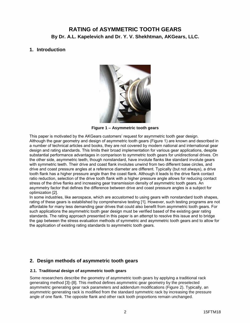
Figure 1 – Asymmetric tooth gears
This paper is motivated by the AKGears customers’ request for asymmetric tooth gear design. Although the gear geometry and design of asymmetric tooth gears (Figure 1) are known and described in a number of technical articles and books, they are not covered by modern national and international gear design and rating standards. This limits their broad implementation for various gear applications, despite substantial performance advantages in comparison to symmetric tooth gears for unidirectional drives. On the other side, asymmetric teeth, though nonstandard, have involute flanks like standard involute gears with symmetric teeth. Their drive and coast flank involutes unwind from two different base circles, and drive and coast pressure angles at a reference diameter are different. Typically (but not always), a drive tooth flank has a higher pressure angle than the coast flank. Although it leads to the drive flank contact ratio reduction, selection of the drive tooth flank with a higher pressure angle allows for reducing contact stress of the drive flanks and increasing gear transmission density of asymmetric tooth gears. An asymmetry factor that defines the difference between drive and coast pressure angles is a subject for optimization [2].In some industries, like aerospace, which are accustomed to using gears with nonstandard tooth shapes, rating of these gears is established by comprehensive testing [1]. However, such testing programs are not affordable for many less demanding gear drives that could also benefit from asymmetric tooth gears. For such applications the asymmetric tooth gear design must be verified based of the existing gear rating standards. The rating approach presented in this paper is an attempt to resolve this issue and to bridge the gap between the stress evaluation methods of symmetric and asymmetric tooth gears and to allow for the application of existing rating standards to asymmetric tooth gears.
2. Design methods of asymmetric tooth gears
2.1. Traditional design of asymmetric tooth gears
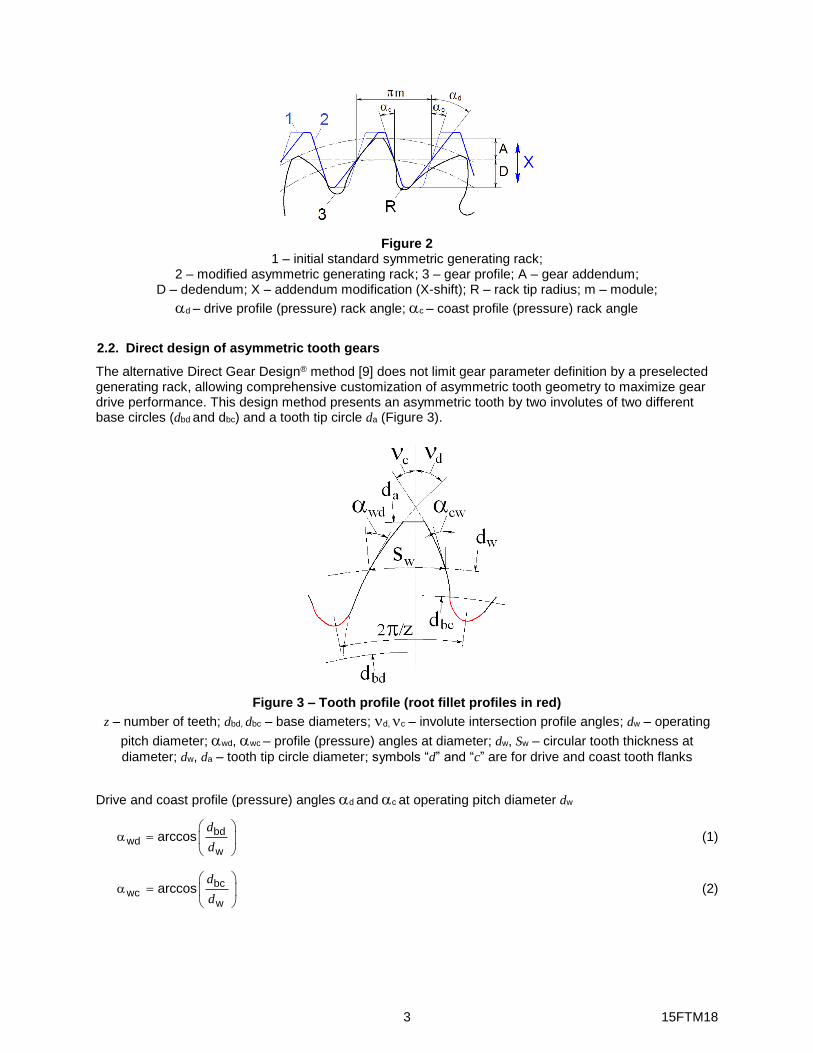
Some researchers describe the geometry of asymmetric tooth gears by applying a traditional rack generating method [3]–[8]. This method defines asymmetric gear geometry by the preselected asymmetric generating gear rack parameters and addendum modifications (Figure 2). Typically, an asymmetric generating rack is modified from the standard symmetric rack by increasing the pressure angle of one flank. The opposite flank and other rack tooth proportions remain unchanged.
3 15FTM18
Figure 2 1 – initial standard symmetric generating rack;
2 – modified asymmetric generating rack; 3 – gear profile; A – gear addendum; D – dedendum; X – addendum modification (X-shift); R – rack tip radius; m – module;
d – drive profile (pressure) rack angle; c – coast profile (pressure) rack angle
2.2. Direct design of asymmetric tooth gears
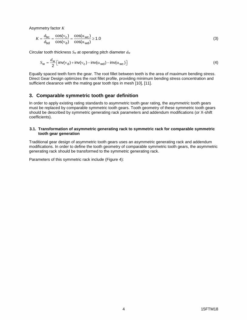
The alternative Direct Gear Design® method [9] does not limit gear parameter definition by a preselected generating rack, allowing comprehensive customization of asymmetric tooth geometry to maximize gear drive performance. This design method presents an asymmetric tooth by two involutes of two different base circles (dbd and dbc) and a tooth tip circle da (Figure 3).
Figure 3 – Tooth profile (root fillet profiles in red)
z – number of teeth; dbd, dbc – base diameters; d, c– involute intersection profile angles; dw – operating
pitch diameter; wd, wc – profile (pressure) angles at diameter; dw, Sw – circular tooth thickness at
diameter; dw, da – tooth tip circle diameter; symbols “d” and “c” are for drive and coast tooth flanks
Drive and coast profile (pressure) angles d andc at operating pitch diameter dw
bdwd
w
arccosd
d
(1)
bcwc
w
arccosd
d
(2)
4 15FTM18
Asymmetry factor K
bc c wc
bd d wd
cos( ) cos( )1.0
cos( ) cos( )
dK
d
(3)
Circular tooth thickness Sw at operating pitch diameter dw
ww d c wd wcinv( ) inv( ) inv( ) inv( )
2
dS (4)
Equally spaced teeth form the gear. The root fillet between teeth is the area of maximum bending stress. Direct Gear Design optimizes the root fillet profile, providing minimum bending stress concentration and sufficient clearance with the mating gear tooth tips in mesh [10], [11].
3. Comparable symmetric tooth gear definition
In order to apply existing rating standards to asymmetric tooth gear rating, the asymmetric tooth gears must be replaced by comparable symmetric tooth gears. Tooth geometry of these symmetric tooth gears should be described by symmetric generating rack parameters and addendum modifications (or X-shift coefficients).
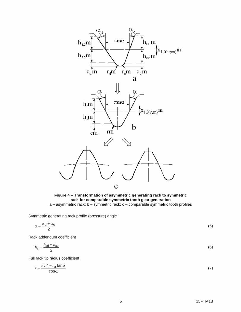
3.1. Transformation of asymmetric generating rack to symmetric rack for comparable symmetric tooth gear generation
Traditional gear design of asymmetric tooth gears uses an asymmetric generating rack and addendum modifications. In order to define the tooth geometry of comparable symmetric tooth gears, the asymmetric generating rack should be transformed to the symmetric generating rack.
Parameters of this symmetric rack include (Figure 4):
5 15FTM18
Figure 4 – Transformation of asymmetric generating rack to symmetric rack for comparable symmetric tooth gear generation
a – asymmetric rack; b – symmetric rack; c – comparable symmetric tooth profiles
Symmetric generating rack profile (pressure) angle
d c
2
(5)
Rack addendum coefficient
h hh
ad ac
a2
(6)
Full rack tip radius coefficient
a/ 4 tan
cos
hr
(7)
6 15FTM18
Clearance coefficient
(1 sin )c r (8)
Addendum modification (X-shift) coefficients
1,2(sym) 1,2(asym)x x (9)
where index “1” and “2” are for the pinion and gear, respectively.
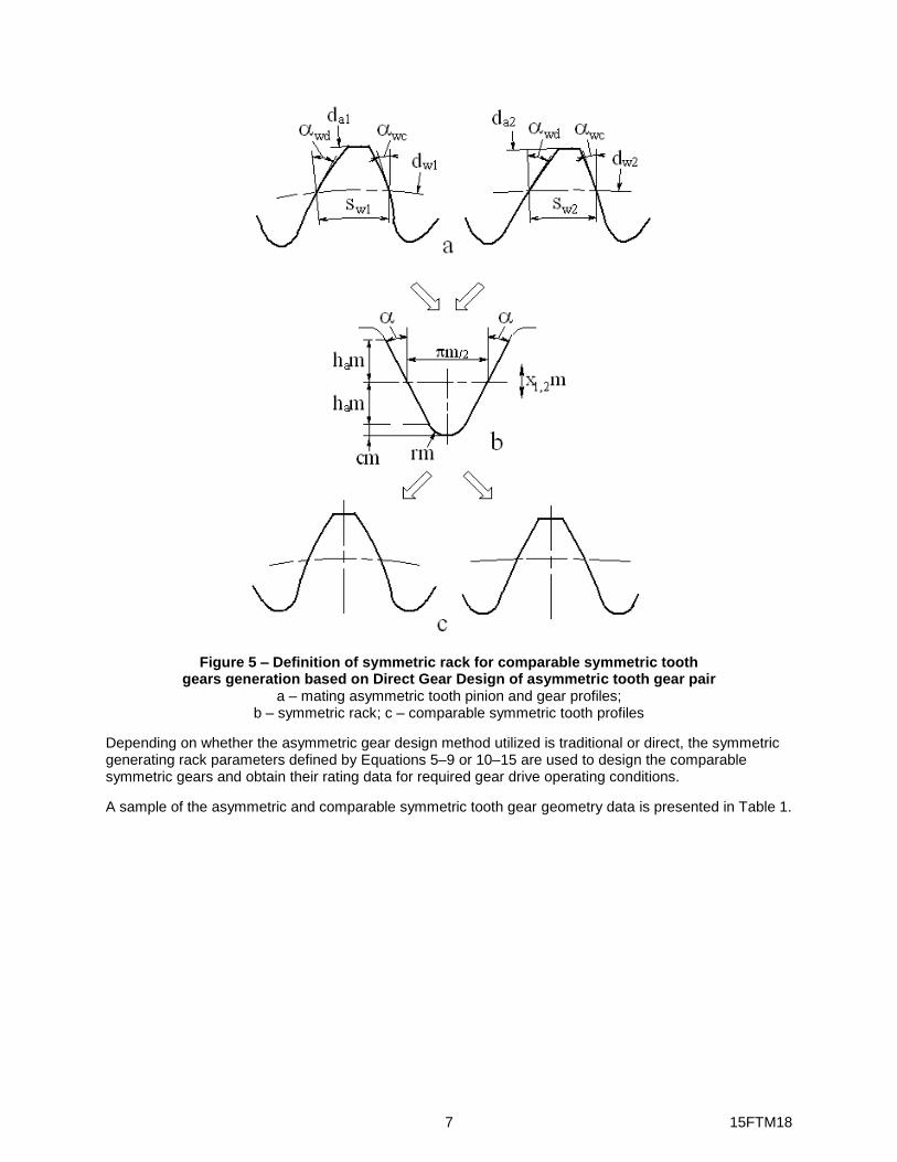
3.2. Definition of symmetric rack for comparable symmetric tooth gear generation based on Direct Gear Design of asymmetric tooth gear pair
Direct gear design of asymmetric tooth gears does not utilize any racks to generate gear tooth geometry parameters. However, in order to define the tooth geometry of comparable symmetric tooth gears that would be used for asymmetric tooth gear rating, the symmetric generating rack should be defined by asymmetric gear parameters.
Parameters of this symmetric rack include (Figure 5):
Symmetric generating rack module
w1 w2
1 2
d dm
z z (10)
where 1z and 2z are numbers of teeth of the pinion and gear, respectively.
Profile (pressure) angle
wd wc
2
(11)
Rack addendum coefficient
d d d dh
m
a1 1 a2 2
a4
(12)
Full rack tip radius coefficient
a w
w
/ 4 tan
cos
hr
(13)
Clearance coefficient
w(1 sin )c r (14)
Addendum modification (X-shift) coefficients
s sx
m
1 21
4 tanand 2 1x x (15)
7 15FTM18
Figure 5 – Definition of symmetric rack for comparable symmetric tooth gears generation based on Direct Gear Design of asymmetric tooth gear pair
a – mating asymmetric tooth pinion and gear profiles; b – symmetric rack; c – comparable symmetric tooth profiles
Depending on whether the asymmetric gear design method utilized is traditional or direct, the symmetric generating rack parameters defined by Equations 5–9 or 10–15 are used to design the comparable symmetric gears and obtain their rating data for required gear drive operating conditions.
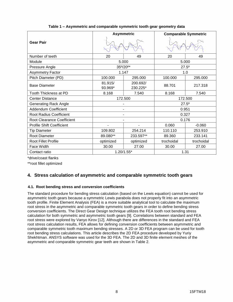
A sample of the asymmetric and comparable symmetric tooth gear geometry data is presented in Table 1.
8 15FTM18
Table 1 – Asymmetric and comparable symmetric tooth gear geometry data
Gear Pair
Asymmetric
Comparable Symmetric
Number of teeth 20 49 20 49
Module 5.000 5.000
Pressure Angle 35º/20º* 27.5º
Asymmetry Factor 1.147 1.0
Pitch Diameter (PD) 100.000 295.000 100.000 295.000
Base Diameter 81.915/
93.969*
200.692/
230.225* 88.701 217.318
Tooth Thickness at PD 8.168 7.540 8.168 7.540
Center Distance 172.500 172.500
Generating Rack Angle - 27.5º
Addendum Coefficient - 0.951
Root Radius Coefficient - 0.327
Root Clearance Coefficient - 0.176
Profile Shift Coefficient - - 0.060 -0.060
Tip Diameter 109.802 254.214 110.110 253.910
Root Diameter 89.080** 233.597** 89.360 233.141
Root Fillet Profile optimized optimized trochoidal trochoidal
Face Width 30.00 27.00 30.00 27.00
Contact ratio 1.20/1.55* 1.31
*drive/coast flanks
**root fillet optimized
4. Stress calculation of asymmetric and comparable symmetric tooth gears
4.1. Root bending stress and conversion coefficients
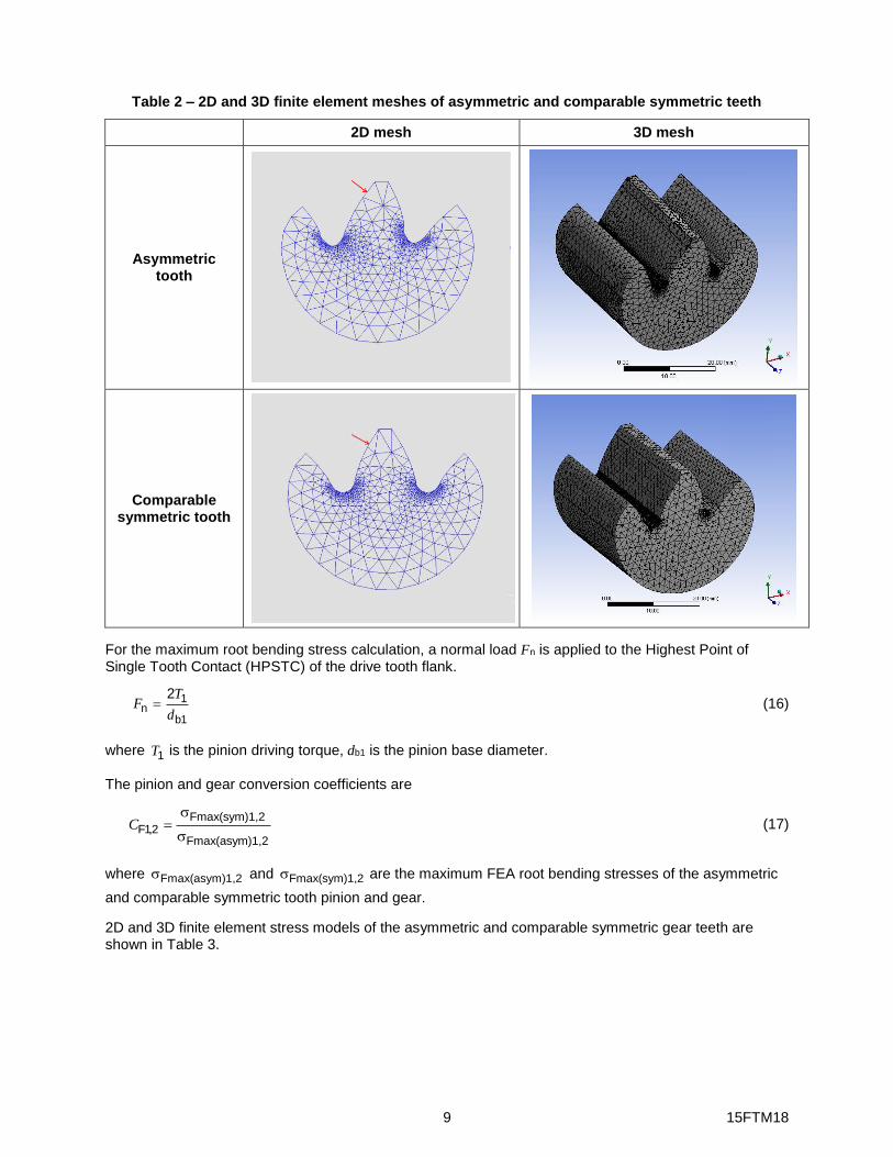
The standard procedure for bending stress calculation (based on the Lewis equation) cannot be used for asymmetric tooth gears because a symmetric Lewis parabola does not properly fit into an asymmetric tooth profile. Finite Element Analysis (FEA) is a more suitable analytical tool to calculate the maximum root stress in the asymmetric and comparable symmetric tooth gears in order to define bending stress conversion coefficients. The Direct Gear Design technique utilizes the FEA tooth root bending stress calculation for both symmetric and asymmetric tooth gears [9]. Correlations between standard and FEA root stress were explored by Vanyo Kirov [12]. Although there are differences in the standard and FEA root stress calculation results, FEA allows for defining conversion coefficients between asymmetric and comparable symmetric tooth maximum bending stresses. A 2D or 3D FEA program can be used for tooth root bending stress calculations. This article describes the 2D FEA procedure developed by Yuriy Shekhtman. ANSYS software was used for the 3D FEA. The 2D and 3D finite element meshes of the asymmetric and comparable symmetric gear teeth are shown in Table 2.
9 15FTM18
Table 2 – 2D and 3D finite element meshes of asymmetric and comparable symmetric teeth
2D mesh 3D mesh
Asymmetric tooth
Comparable symmetric tooth
For the maximum root bending stress calculation, a normal load Fn is applied to the Highest Point of Single Tooth Contact (HPSTC) of the drive tooth flank.
1n
b1
2TF
d (16)
where 1T is the pinion driving torque, db1 is the pinion base diameter.
The pinion and gear conversion coefficients are
Fmax(sym)1,2F1,2
Fmax(asym)1,2
C
(17)
where Fmax(asym)1,2 and Fmax(sym)1,2 are the maximum FEA root bending stresses of the asymmetric
and comparable symmetric tooth pinion and gear.
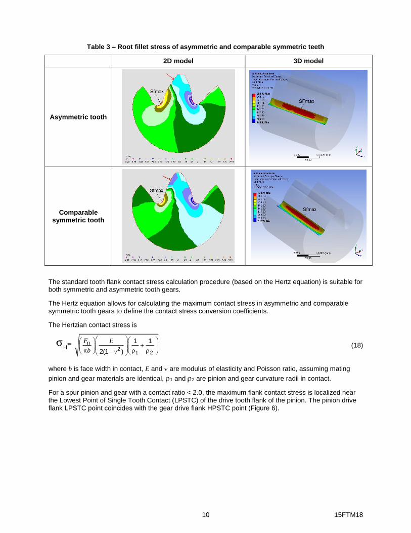
2D and 3D finite element stress models of the asymmetric and comparable symmetric gear teeth are shown in Table 3.
10 15FTM18
Table 3 – Root fillet stress of asymmetric and comparable symmetric teeth
2D model 3D model
Asymmetric tooth
Comparable symmetric tooth
The standard tooth flank contact stress calculation procedure (based on the Hertz equation) is suitable for both symmetric and asymmetric tooth gears.
The Hertz equation allows for calculating the maximum contact stress in asymmetric and comparable symmetric tooth gears to define the contact stress conversion coefficients.
The Hertzian contact stress is
nH 2
1 2
1 1
2(1 )
F E
b v
σ =
(18)
where b is face width in contact, E and are modulus of elasticity and Poisson ratio, assuming mating
pinion and gear materials are identical, 1 and 2 are pinion and gear curvature radii in contact.
For a spur pinion and gear with a contact ratio < 2.0, the maximum flank contact stress is localized near the Lowest Point of Single Tooth Contact (LPSTC) of the drive tooth flank of the pinion. The pinion drive flank LPSTC point coincides with the gear drive flank HPSTC point (Figure 6).
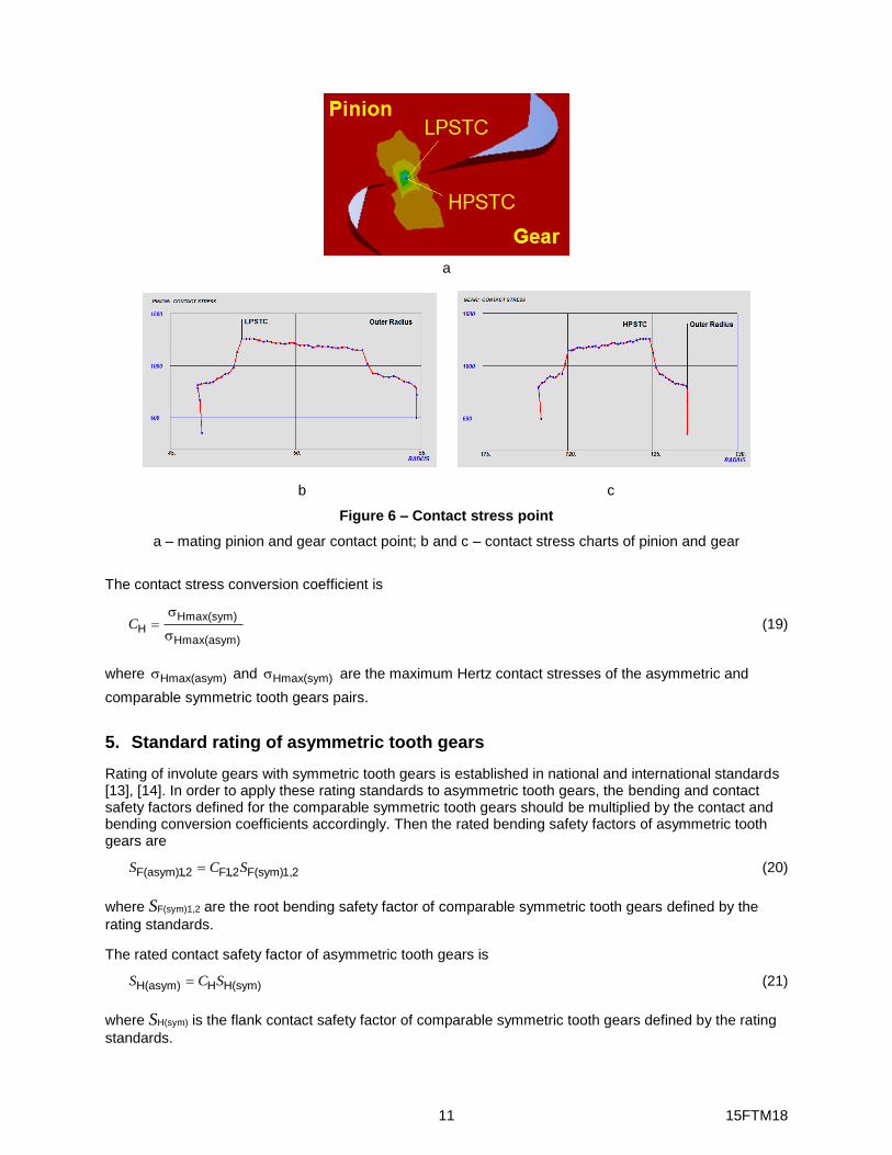
11 15FTM18
a
b c
Figure 6 – Contact stress point
a – mating pinion and gear contact point; b and c – contact stress charts of pinion and gear
The contact stress conversion coefficient is
Hmax(sym)H
Hmax(asym)
C
(19)
where Hmax(asym) and Hmax(sym) are the maximum Hertz contact stresses of the asymmetric and
comparable symmetric tooth gears pairs.
5. Standard rating of asymmetric tooth gears
Rating of involute gears with symmetric tooth gears is established in national and international standards [13], [14]. In order to apply these rating standards to asymmetric tooth gears, the bending and contact safety factors defined for the comparable symmetric tooth gears should be multiplied by the contact and bending conversion coefficients accordingly. Then the rated bending safety factors of asymmetric tooth gears are
F(asym)1,2 F1,2 F(sym)1,2S C S (20)
where SF(sym)1,2 are the root bending safety factor of comparable symmetric tooth gears defined by the
rating standards.
The rated contact safety factor of asymmetric tooth gears is
H(asym) H H(sym)S C S (21)
where SH(sym) is the flank contact safety factor of comparable symmetric tooth gears defined by the rating
standards.
12 15FTM18
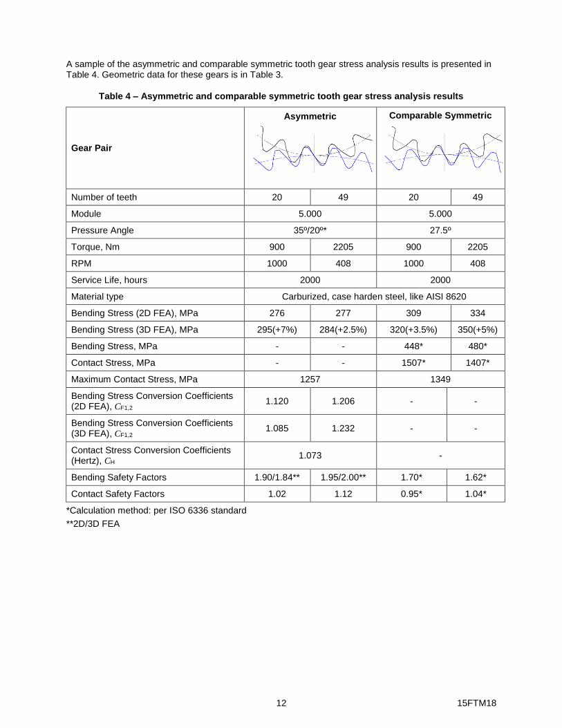
A sample of the asymmetric and comparable symmetric tooth gear stress analysis results is presented in Table 4. Geometric data for these gears is in Table 3.
Table 4 – Asymmetric and comparable symmetric tooth gear stress analysis results
Gear Pair
Asymmetric Comparable Symmetric
Number of teeth 20 49 20 49
Module 5.000 5.000
Pressure Angle 35º/20º* 27.5º
Torque, Nm 900 2205 900 2205
RPM 1000 408 1000 408
Service Life, hours 2000 2000
Material type Carburized, case harden steel, like AISI 8620
Bending Stress (2D FEA), MPa 276 277 309 334
Bending Stress (3D FEA), MPa 295(+7%) 284(+2.5%) 320(+3.5%) 350(+5%)
Bending Stress, MPa - - 448* 480*
Contact Stress, MPa - - 1507* 1407*
Maximum Contact Stress, MPa 1257 1349
Bending Stress Conversion Coefficients (2D FEA), CF1,2
1.120 1.206 - -
Bending Stress Conversion Coefficients (3D FEA), CF1,2
1.085 1.232 - -
Contact Stress Conversion Coefficients (Hertz), CH
1.073 -
Bending Safety Factors 1.90/1.84** 1.95/2.00** 1.70* 1.62*
Contact Safety Factors 1.02 1.12 0.95* 1.04*
*Calculation method: per ISO 6336 standard
**2D/3D FEA
13 15FTM18
Summary
1. The article outlines a simple and effective approach to rating asymmetric tooth gears using existingsymmetric tooth gear rating standards that includes:
- conversion of the asymmetric tooth geometry into the comparable symmetric tooth geometry and definition of its generating rack;
- calculation of maximum bending stresses using the 2D or 3D FEA to both asymmetric and comparable symmetric gear teeth;
- calculation of maximum contact stresses for both asymmetric and comparable symmetric gear teeth using the Hertz equation;
- definition of the bending and contact stress conversion coefficients;
- standard stress analysis for the comparable symmetric gear tooth and definition of the contact and bending safety factors;
- definition of the contact and bending safety factors for asymmetric tooth gears using the symmetric tooth gear safety factors and the bending and contact stress conversion coefficients.
2. The presented asymmetric tooth gear rating approach allows expanding implementation of these types of gears in many unidirectional gear drives, maximizing their performance.
3. This approach might be a temporary solution until the asymmetric tooth gear design standards will be developed by AGMA or ISO. However, it takes long time to create a new gear rating standard. Meanwhile, the suggested approach can be used today for rating of the asymmetric tooth gears.
14 15FTM18
6. Bibliography
[2] Brown, F.W., S.R. Davidson, D.B. Hanes and D.J. Weires, A. L. Kapelevich, Analysis and Testing of Gears with Asymmetric Involute Tooth Form and Optimized Fillet Form for Potential Application in Helicopter Main Drives, AGMA Fall Technical Meeting, Milwaukee, Wisconsin, October 18–19, 2010, (10FTM14), also published in Gear Technology, June/July 2011, 46–55.
[1] Kapelevich, A. L. Asymmetric Gears: Parameter Selection Approach. Gear Technology. June/July 2011, 48–51.
[3] DiFrancesco, G. and S. Marini. Structural Analysis of Asymmetrical Teeth: Reduction of Size and Weight. Gear Technology. September/October 1997, 47–51.
[4] Gang, G. and T. Nakanishi. Enhancement of bending load carrying capacity of gears using an asymmetric involute tooth. Paper presented at the JSME International Conference on Motion and Transmissions (MPT2001-Fukuoka), 2001, Fukuoka, Japan.
[5] Karpat, F. K., Cavdar, and F.C. Babalik, Computer aided analysis of involute spur gears with asymmetric teeth. VDI Berichte. 1904 I 2005: 145–163.
[6] Brecher, C., and Schafer, J. Potentials of asymmetric tooth geometries for the optimization of involute cylindrical gears. VDI Berichte. 1904 I 2005: 705–720.
[7] Pedersen, N.L. Improving bending stress in spur gears using asymmetric gears and shape optimization. Mechanism and Machine Theory. 45 2010: 1707–1720.
[8] Wang, S., G. R. Liu, G. Y. Zhang, L. Chen. Design of Asymmetric Gear and Accurate Bending Stress Analysis Using the ES-PIM with Triangular Mesh. International Journal of Computational Methods. Vol. 8, No. 4. 2011. World Scientific Publishing Company: 759–772.
[9] Kapelevich A.L. Direct Gear Design, CRC Press, 2013
[10] Kapelevich, A. L. and Y. V. Shekhtman. Tooth Fillet Profile Optimization for Gears with Symmetric and Asymmetric Teeth. Gear Technology. September/October 2009, 73–79
[11] AKGears’ Tooth Root Fillet Optimization software www.akgears.com/software.htm, 2015.
[12] Kirov V. Comparing AGMA and FEA Calculations, Gear Solutions. February 2011, 39–45.
[13] Standard ISO 6336. 2006. Calculation of load capacity of spur and helical gears.
[14] Standard ANSI/AGMA 2001-D04. 2004. Fundamental Rating Factors and Calculation Methods for Involute Spur and Helical Gear Teeth.
Top Related