


Languages
Pages
Legal


“RAPID SYSTEM PROTOTYPING OF ELECTRONIC SYSTEMS:
A VHDL OVERVIEW”By
Luis E. Navarrete, MSEEOrlando J. Hernandez, Ph.D.
Tecnologías de la Información: Telecomunicaciones, Aplicaciones en Procesamiento Digital de Señales y Diseño Digital con VHDL
UNIVERSIDAD DEL NORTEMay 21 - 23, 2003
May 21 - 23, 2003
Tecnologías de la Información: Telecomunicaciones, Aplicaciones en Procesamiento Digital de Señales y Diseño Digital con VHDL
UNIVERSIDAD DEL NORTE 2
Presentation Overview
Modern Electronic Design OverviewDigital Logic TechnologiesProgrammable Logic Devices - FPGAs
Introduction to VHDL – Part IIntroduction to VHDL – Part II
AND, OR, HALF ADDER, FULL ADDERIntroduction to VHDL – Part III
ALU DesignControl and Data Path Organization
Finite State Machines, Digital FilterIntroduction to MAX+PLUS IIImplementations and Examples on the ALTERA UP1 BoardQ&A Sessions
May 21 - 23, 2003
Tecnologías de la Información: Telecomunicaciones, Aplicaciones en Procesamiento Digital de Señales y Diseño Digital con VHDL
UNIVERSIDAD DEL NORTE 3
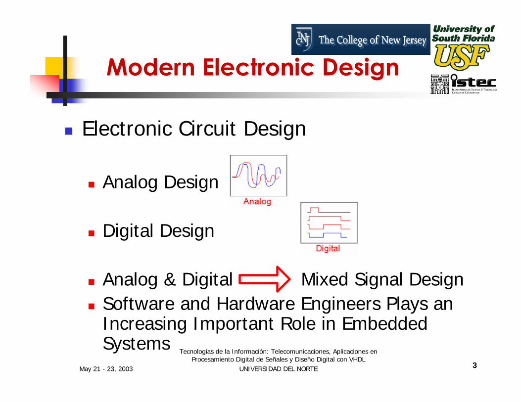
Modern Electronic Design
Electronic Circuit Design
Analog Design
Digital Design
Analog & Digital Mixed Signal DesignSoftware and Hardware Engineers Plays an Increasing Important Role in Embedded Systems

May 21 - 23, 2003
Tecnologías de la Información: Telecomunicaciones, Aplicaciones en Procesamiento Digital de Señales y Diseño Digital con VHDL
UNIVERSIDAD DEL NORTE 4
Digital Logic Technologies
Digital Logic
Standard Logic
Programmable Logic Devices
(PLDs)
Full Custom
ASICs ASICs
TTL74xx
CMOS4xxx
PLA
PAL
CPLD
FPGA
Gate Array
Standard Cell VLSI
Microproc. & RAMsConfigurable
Standard Cells

May 21 - 23, 2003
Tecnologías de la Información: Telecomunicaciones, Aplicaciones en Procesamiento Digital de Señales y Diseño Digital con VHDL
UNIVERSIDAD DEL NORTE 5
Digital Logic TechnologiesProgrammable Logic Devices PLD:
Chips that contains relatively large amounts of logic circuitry with a structure that is not fixed. Introduced in the 1970’s. Several types of PLD’s have been available:
Programmable Logic Array (PLA)Programmable Array Logic (PAL)Complex Programmable Logic Devices (CPLDs)Field Programmable Gate Arrays (FPGAs)

May 21 - 23, 2003
Tecnologías de la Información: Telecomunicaciones, Aplicaciones en Procesamiento Digital de Señales y Diseño Digital con VHDL
UNIVERSIDAD DEL NORTE 6
Digital Logic TechnologiesProgrammable Logic Array PLA:
Based on the idea that logic functions can be realized in sum-of-products form.A PLA comprises a programmable collection of AND gates that feeds a set of OR gates, configured to realize any sum-of-product functions of the PLA Inputs

May 21 - 23, 2003
Tecnologías de la Información: Telecomunicaciones, Aplicaciones en Procesamiento Digital de Señales y Diseño Digital con VHDL
UNIVERSIDAD DEL NORTE 7
Digital Logic TechnologiesProgrammable Logic Array PLA:
PLA, Schematic:
May 21 - 23, 2003
Tecnologías de la Información: Telecomunicaciones, Aplicaciones en Procesamiento Digital de Señales y Diseño Digital con VHDL
UNIVERSIDAD DEL NORTE 8
Digital Logic TechnologiesProgrammable Array Logic PAL:
In a PLA both the AND and the OR planes are programmable. Historically the programmable switches presents two difficulties for the manufacturers, they are hard to fabricate and reduced speed-performance.
May 21 - 23, 2003
Tecnologías de la Información: Telecomunicaciones, Aplicaciones en Procesamiento Digital de Señales y Diseño Digital con VHDL
UNIVERSIDAD DEL NORTE 9
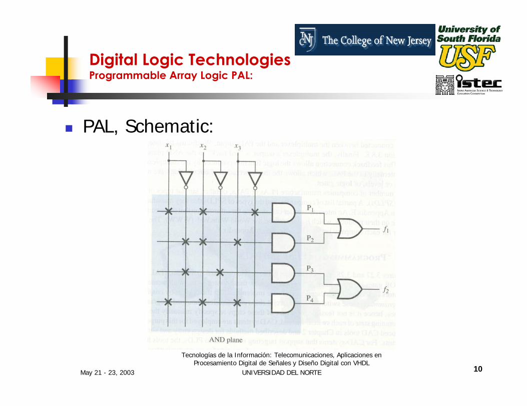
Digital Logic TechnologiesProgrammable Array Logic PAL:
These Drawbacks led to the development of a device were only the AND Plane is programmable while the OR plane remains fixed. This devices were called the PALs.
May 21 - 23, 2003
Tecnologías de la Información: Telecomunicaciones, Aplicaciones en Procesamiento Digital de Señales y Diseño Digital con VHDL
UNIVERSIDAD DEL NORTE 10
Digital Logic TechnologiesProgrammable Array Logic PAL:
PAL, Schematic:

May 21 - 23, 2003
Tecnologías de la Información: Telecomunicaciones, Aplicaciones en Procesamiento Digital de Señales y Diseño Digital con VHDL
UNIVERSIDAD DEL NORTE 11
Digital Logic TechnologiesComplex Programmable Logic Devices CPLDs:
CPLDs were created as a substitute for the PLAs and PALs which are useful for implementing a wide variety of small digital circuits. This small digital circuits will be limited to a relatively small amount of inputs and outputs.

May 21 - 23, 2003
Tecnologías de la Información: Telecomunicaciones, Aplicaciones en Procesamiento Digital de Señales y Diseño Digital con VHDL
UNIVERSIDAD DEL NORTE 12
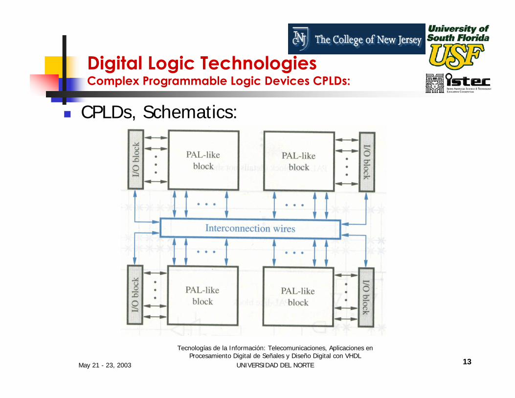
Digital Logic TechnologiesComplex Programmable Logic Devices CPLDs:
For implementing more complex circuits, either multiple PLAs or PALscan be used or a CPLD. A CPLD comprises multiple circuit blocks on a chip, with internal wiring resources to connect the circuit blocks. Each circuit block is similar to a PLA or a PAL.
May 21 - 23, 2003
Tecnologías de la Información: Telecomunicaciones, Aplicaciones en Procesamiento Digital de Señales y Diseño Digital con VHDL
UNIVERSIDAD DEL NORTE 13
CPLDs, Schematics:
Digital Logic TechnologiesComplex Programmable Logic Devices CPLDs:

May 21 - 23, 2003
Tecnologías de la Información: Telecomunicaciones, Aplicaciones en Procesamiento Digital de Señales y Diseño Digital con VHDL
UNIVERSIDAD DEL NORTE 14
Digital Logic TechnologiesField Programmable Gate Arrays FPGAs:
Is a programmable logic device that supports implementation of relatively large logic circuits (Much more than 20,000 gates). FPGAs, does not contains AND or OR planes as the CPLDs. Instead, FPGAs provide logic blocks for implementation of the required functions.
May 21 - 23, 2003
Tecnologías de la Información: Telecomunicaciones, Aplicaciones en Procesamiento Digital de Señales y Diseño Digital con VHDL
UNIVERSIDAD DEL NORTE 15
Digital Logic TechnologiesField Programmable Gate Arrays FPGAs:
They contain tree main types of resources:Logic Blocks I/O blocks for connecting to the package pinsand interconnection wires and switches
More sophisticated state of the art FPGAs also contain:
Complex I/OsMemoriesAnalogCustom laid out processors

May 21 - 23, 2003
Tecnologías de la Información: Telecomunicaciones, Aplicaciones en Procesamiento Digital de Señales y Diseño Digital con VHDL
UNIVERSIDAD DEL NORTE 16
FPGAs, Schematics:
Digital Logic TechnologiesField Programmable Gate Arrays FPGAs:

May 21 - 23, 2003
Tecnologías de la Información: Telecomunicaciones, Aplicaciones en Procesamiento Digital de Señales y Diseño Digital con VHDL
UNIVERSIDAD DEL NORTE 17
Digital Logic TechnologiesApplication Specific Integrated Circuit, ASICs:
Chips that are design using state of the art VLSI technologies and that are tailored to some specific needs (or applications). In the 1980’s Application Specific Integrated Circuits (ASIC) designs were focused to meet time-to-market and customers specific requirements.

May 21 - 23, 2003
Tecnologías de la Información: Telecomunicaciones, Aplicaciones en Procesamiento Digital de Señales y Diseño Digital con VHDL
UNIVERSIDAD DEL NORTE 18
Digital Logic TechnologiesApplication Specific Integrated Circuit, ASICs:
There are several integrated circuits design options:
Standard Cell DesignGate Array
(are among the main ones).Emerging technologies are combining the density and cost efficiency of standard cells with the flexibility and quick design times of gate arrays: configurable standard cells

May 21 - 23, 2003
Tecnologías de la Información: Telecomunicaciones, Aplicaciones en Procesamiento Digital de Señales y Diseño Digital con VHDL
UNIVERSIDAD DEL NORTE 19
Digital Logic TechnologiesStandard Cell Design:
Is a design methodology where a library of macros (cells), which are predefined and pre-laid-out, is provided by a vendor. The user designs his/her circuit with these cells (logic function blocks) resulting in a schematic defining the interconnects among selected cells.

May 21 - 23, 2003
Tecnologías de la Información: Telecomunicaciones, Aplicaciones en Procesamiento Digital de Señales y Diseño Digital con VHDL
UNIVERSIDAD DEL NORTE 20
Digital Logic TechnologiesStandard Cell Design:
Typical libraries are created with low gate level primitives such as: AND, OR, NAND, NOR, XOR, Inverters, flip-flops, registers and other similar components.

May 21 - 23, 2003
Tecnologías de la Información: Telecomunicaciones, Aplicaciones en Procesamiento Digital de Señales y Diseño Digital con VHDL
UNIVERSIDAD DEL NORTE 21
Digital Logic TechnologiesGate Array Design:
The Gate Array design uses a custom interconnection pattern of an array of uncommitted logic gates. These are called Gate Arrays. Wafers of chips containing the uncommitted logic gate arrays can be pre-fabricated up to the point of the final metallization steps which creates the logic personalization.
May 21 - 23, 2003
Tecnologías de la Información: Telecomunicaciones, Aplicaciones en Procesamiento Digital de Señales y Diseño Digital con VHDL
UNIVERSIDAD DEL NORTE 22
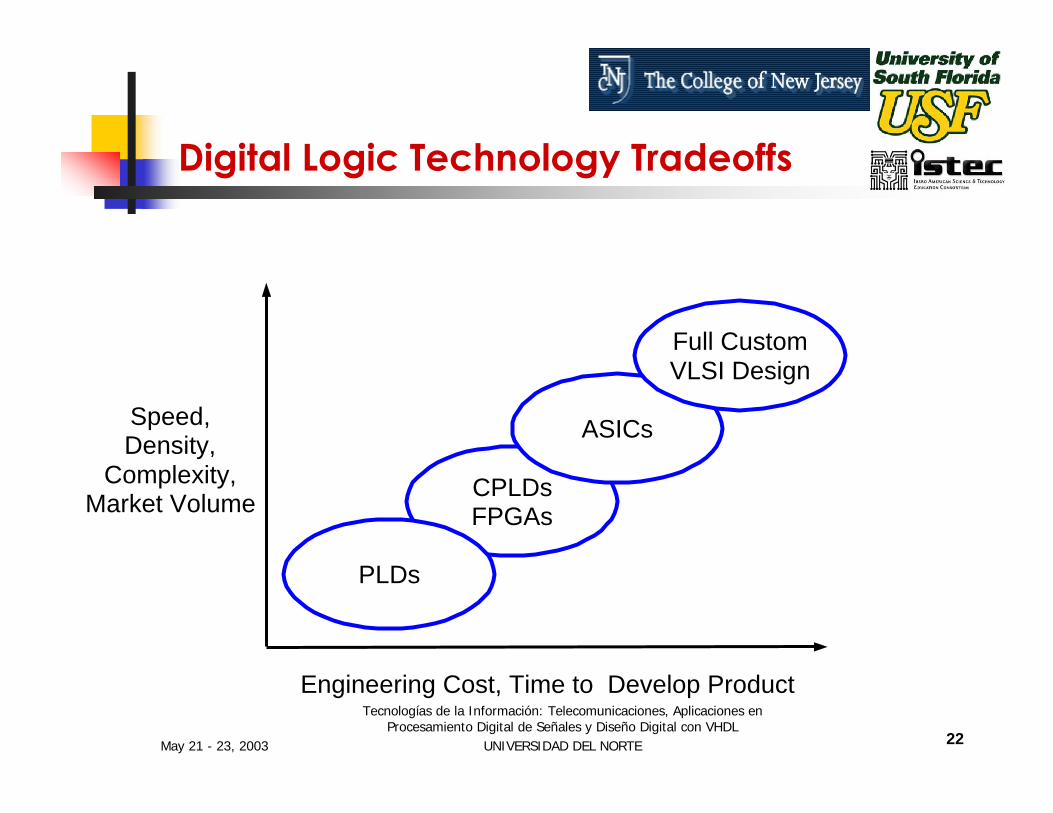
Digital Logic Technology Tradeoffs
CPLDsFPGAs
PLDs
ASICs
Full CustomVLSI Design
Speed,Density,
Complexity,Market Volume
Engineering Cost, Time to Develop Product

May 21 - 23, 2003
Tecnologías de la Información: Telecomunicaciones, Aplicaciones en Procesamiento Digital de Señales y Diseño Digital con VHDL
UNIVERSIDAD DEL NORTE 23
FPGAs are Integrated Circuits Whose Internal Functional Operation is Defined by the User RAPID SYSTEM PROTOTYPING OF ELECTRONIC SYSTEMS.They can be Programmed using a Hardware description Language, VHDL
Field Programmable Logic Arrays, FPGAs

May 21 - 23, 2003
Tecnologías de la Información: Telecomunicaciones, Aplicaciones en Procesamiento Digital de Señales y Diseño Digital con VHDL
UNIVERSIDAD DEL NORTE 24
UP1 Development Boardwww.altera.com
May 21 - 23, 2003
Tecnologías de la Información: Telecomunicaciones, Aplicaciones en Procesamiento Digital de Señales y Diseño Digital con VHDL
UNIVERSIDAD DEL NORTE 25
Session I
INTRODUCTION TO VHDL – PART I

May 21 - 23, 2003
Tecnologías de la Información: Telecomunicaciones, Aplicaciones en Procesamiento Digital de Señales y Diseño Digital con VHDL
UNIVERSIDAD DEL NORTE 26
Design Automation
Need To Keep With Rapid Changes, Electronic Products Have To Be Designed Extremely QuicklyElectronic Design Automation (EDA)
Design EntrySimulationSynthesisDesign Validation & Test
May 21 - 23, 2003
Tecnologías de la Información: Telecomunicaciones, Aplicaciones en Procesamiento Digital de Señales y Diseño Digital con VHDL
UNIVERSIDAD DEL NORTE 27
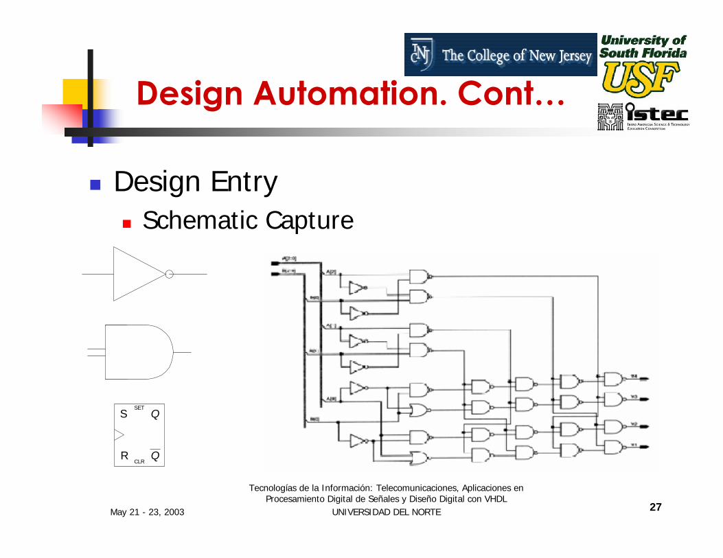
Design Automation. Cont…
Design EntrySchematic Capture
Q
QSET
CLR
S
R

May 21 - 23, 2003
Tecnologías de la Información: Telecomunicaciones, Aplicaciones en Procesamiento Digital de Señales y Diseño Digital con VHDL
UNIVERSIDAD DEL NORTE 28
Design Automation. Cont…
Design Entry - Textual Form: VHDL (VHSIC Hardware Description Language) VHSIC (Very High Speed Integrated Circuits)
May 21 - 23, 2003
Tecnologías de la Información: Telecomunicaciones, Aplicaciones en Procesamiento Digital de Señales y Diseño Digital con VHDL
UNIVERSIDAD DEL NORTE 29
Design Automation. Cont…
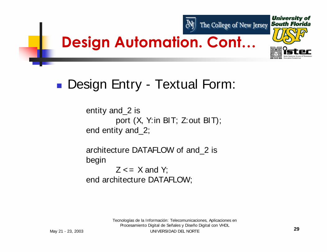
Design Entry - Textual Form:
entity and_2 isport (X, Y:in BIT; Z:out BIT);
end entity and_2;
architecture DATAFLOW of and_2 isbegin
Z <= X and Y;end architecture DATAFLOW;

May 21 - 23, 2003
Tecnologías de la Información: Telecomunicaciones, Aplicaciones en Procesamiento Digital de Señales y Diseño Digital con VHDL
UNIVERSIDAD DEL NORTE 30
VHDL: Very High Speed Integrated Circuit (VHSIC) Hardware Description Language.
VHDL Is an Industry Standard Language to Describe Hardware From the Abstract to Concrete Level.
Introduction To VHDL
May 21 - 23, 2003
Tecnologías de la Información: Telecomunicaciones, Aplicaciones en Procesamiento Digital de Señales y Diseño Digital con VHDL
UNIVERSIDAD DEL NORTE 31
BRIEF HISTORY OF VHDL
VHDL is a Derivative of the VHSIC Program by US Dept. of Defense Along With IBM, Texas Instruments, and Intermetrics.
In 1986 VHDL Became IEEE Standard and After Several Revisions. It Was Adopted As the IEEE 1076 Standard.
May 21 - 23, 2003
Tecnologías de la Información: Telecomunicaciones, Aplicaciones en Procesamiento Digital de Señales y Diseño Digital con VHDL
UNIVERSIDAD DEL NORTE 32
BRIEF HISTORY OF VHDL
In 1999 the Analog and Mixed Signal Extensions Were Added to VHDL (VHDL-AMS)
In 2000 the latest upgrade (Object Oriented added…)
May 21 - 23, 2003
Tecnologías de la Información: Telecomunicaciones, Aplicaciones en Procesamiento Digital de Señales y Diseño Digital con VHDL
UNIVERSIDAD DEL NORTE 33
MOTIVATION
Need a Method to Quickly Design, Implement, Test and Document Increasingly Complex Digital Systems.
Schematic and Boolean Equations Inadequate for Million-Gate ICs.
Design Portability

May 21 - 23, 2003
Tecnologías de la Información: Telecomunicaciones, Aplicaciones en Procesamiento Digital de Señales y Diseño Digital con VHDL
UNIVERSIDAD DEL NORTE 34
What is VHDL?
A Design entry languageA Simulation modeling language.A Verification language.A Standard language.As simple or complex as required.

May 21 - 23, 2003
Tecnologías de la Información: Telecomunicaciones, Aplicaciones en Procesamiento Digital de Señales y Diseño Digital con VHDL
UNIVERSIDAD DEL NORTE 35
For Design Specification (“Specify”)
For Design Entry (“Capture”)
For Design Simulation (“Verify”)
For Design Documentation (“formalize”)
As an Alternate to Schematics
Specify
Capture
Verify
Formalize
Implement
How is VHDL Used?

May 21 - 23, 2003
Tecnologías de la Información: Telecomunicaciones, Aplicaciones en Procesamiento Digital de Señales y Diseño Digital con VHDL
UNIVERSIDAD DEL NORTE 36
Design Entry
Synthesis Functional Simulation
Device Mapping Timing Simulation
Device
Test Development
FPGA Design Process
VHDL Can Be Used for Both Design and Test Development

May 21 - 23, 2003
Tecnologías de la Información: Telecomunicaciones, Aplicaciones en Procesamiento Digital de Señales y Diseño Digital con VHDL
UNIVERSIDAD DEL NORTE 37
VHDL is highly beneficial to use as a structured, top down approach to design.VHDL makes it easy to build, use, and reuse libraries of circuit elements.VHDL can greatly improve your chances of moving into more advanced tools and device targets.
When Should VHDL Be Used?
May 21 - 23, 2003
Tecnologías de la Información: Telecomunicaciones, Aplicaciones en Procesamiento Digital de Señales y Diseño Digital con VHDL
UNIVERSIDAD DEL NORTE 38
Advantages of VHDL
The Ability to Code the Behavior and to Synthesize an Actual Circuit.
Power and Flexibility
Device (specific FPGA) Independent Design
May 21 - 23, 2003
Tecnologías de la Información: Telecomunicaciones, Aplicaciones en Procesamiento Digital de Señales y Diseño Digital con VHDL
UNIVERSIDAD DEL NORTE 39
Portability Among Tools and Devices
Fast Switch Level Simulations
Quick Time to Market and Low Cost
Industry Standard
Advantages of VHDL Cont…

May 21 - 23, 2003
Tecnologías de la Información: Telecomunicaciones, Aplicaciones en Procesamiento Digital de Señales y Diseño Digital con VHDL
UNIVERSIDAD DEL NORTE 40
Getting Started with VHDL
Its Easy To Get Started With VHDL, But Its Difficult To Master It.To Begin With, A Subset of The Language Can Be Learned To Write Useful Models.Later More Complex Features Can Be Learned To Implement Complex Circuits.

May 21 - 23, 2003
Tecnologías de la Información: Telecomunicaciones, Aplicaciones en Procesamiento Digital de Señales y Diseño Digital con VHDL
UNIVERSIDAD DEL NORTE 41
A First look at VHDL
Lets start with a simple Combinational circuit: an 8-bit Comparator.

May 21 - 23, 2003
Tecnologías de la Información: Telecomunicaciones, Aplicaciones en Procesamiento Digital de Señales y Diseño Digital con VHDL
UNIVERSIDAD DEL NORTE 42
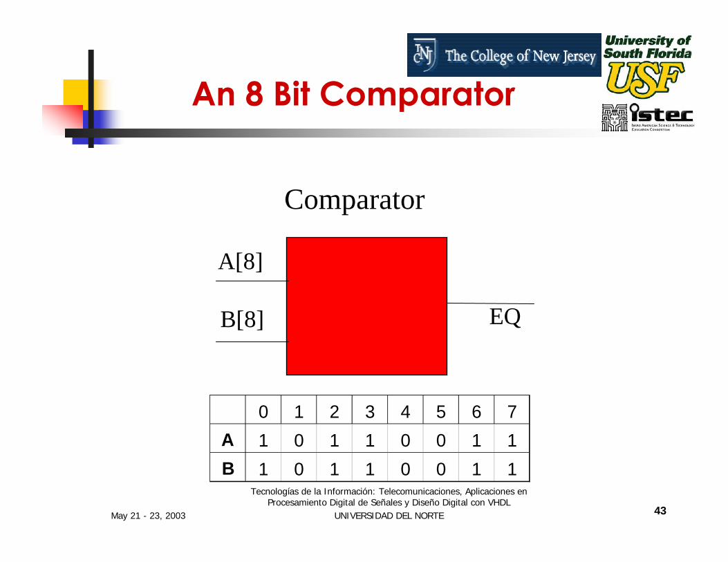
An 8 Bit Comparator
Comparator Specifications:Two 8-bit inputs1-bit Output Output is 1 if the inputs match or 0 if they differ.
May 21 - 23, 2003
Tecnologías de la Información: Telecomunicaciones, Aplicaciones en Procesamiento Digital de Señales y Diseño Digital con VHDL
UNIVERSIDAD DEL NORTE 43
0 1 2 3 4 5 6 7A 1 0 1 1 0 0 1 1B 1 0 1 1 0 0 1 1
An 8 Bit Comparator
Comparator
A[8]
EQB[8]

May 21 - 23, 2003
Tecnologías de la Información: Telecomunicaciones, Aplicaciones en Procesamiento Digital de Señales y Diseño Digital con VHDL
UNIVERSIDAD DEL NORTE 44
-- Eight-bit Comparatorentity compare is
port (A, B : in std_logic_vector (0 to 7);EQ : out std_logic);
end compare;
architecture comp of compare isbegin
EQ <= ‘1’ when (A=B) else ‘0’;end comp;
An entity declaration that defines the inputs and outputs - the ports of the circuitAn architecture that defines the function of the circuit
Comparator VHDL Source Code
May 21 - 23, 2003
Tecnologías de la Información: Telecomunicaciones, Aplicaciones en Procesamiento Digital de Señales y Diseño Digital con VHDL
UNIVERSIDAD DEL NORTE 45
Entities and Architectures
Every VHDL design description has at least one entity/architecture pair.
A large design has many entity / architecture pairs and are connected to form the complete circuit.
May 21 - 23, 2003
Tecnologías de la Información: Telecomunicaciones, Aplicaciones en Procesamiento Digital de Señales y Diseño Digital con VHDL
UNIVERSIDAD DEL NORTE 46
What is an Entity?
An entity declaration describes the circuit as it appears from “outside”-from perspective of its input and output interfaces.
An entity declaration is analogous to a block symbol on a schematic.
May 21 - 23, 2003
Tecnologías de la Información: Telecomunicaciones, Aplicaciones en Procesamiento Digital de Señales y Diseño Digital con VHDL
UNIVERSIDAD DEL NORTE 47
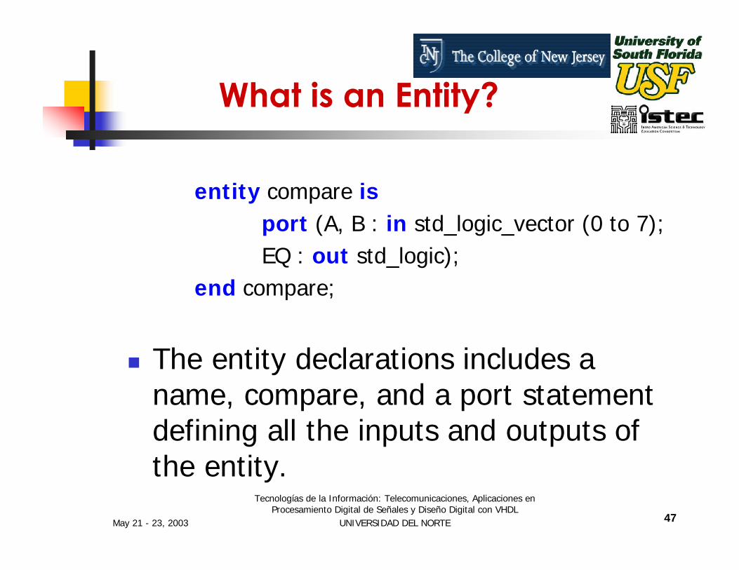
entity compare isport (A, B : in std_logic_vector (0 to 7);EQ : out std_logic);
end compare;
The entity declarations includes a name, compare, and a port statement defining all the inputs and outputs of the entity.
What is an Entity?

May 21 - 23, 2003
Tecnologías de la Información: Telecomunicaciones, Aplicaciones en Procesamiento Digital de Señales y Diseño Digital con VHDL
UNIVERSIDAD DEL NORTE 48
What is an Architecture?
Architecture Describes the Actual Function - or Contents of the Entity to Which It Is Bound.
Architecture Is Roughly Analogous to a Lower Level Schematic Referenced by the High Level Functional Block Symbol.

May 21 - 23, 2003
Tecnologías de la Información: Telecomunicaciones, Aplicaciones en Procesamiento Digital de Señales y Diseño Digital con VHDL
UNIVERSIDAD DEL NORTE 49
What is an Architecture?
architecture comp of compare isbegin
EQ <= ‘1’ when (A=B) else ‘0’;end comp;
The architecture declaration begins with a unique name, comp, followed by the name of the entity to which the architecture is bound, in this case compare.

May 21 - 23, 2003
Tecnologías de la Información: Telecomunicaciones, Aplicaciones en Procesamiento Digital de Señales y Diseño Digital con VHDL
UNIVERSIDAD DEL NORTE 50
What is an Architecture?
architecture comp of compare isbegin
EQ <= ‘1’ when (A=B) else ‘0’;end comp;
Between the keywords begin and end is found the actual functional description of the comparator.
May 21 - 23, 2003
Tecnologías de la Información: Telecomunicaciones, Aplicaciones en Procesamiento Digital de Señales y Diseño Digital con VHDL
UNIVERSIDAD DEL NORTE 51
Data Types
VHDL’s high level data types allow data to be represented in much the same way as in high-level programming languages.
A data type is an abstract representation of stored data.
May 21 - 23, 2003
Tecnologías de la Información: Telecomunicaciones, Aplicaciones en Procesamiento Digital de Señales y Diseño Digital con VHDL
UNIVERSIDAD DEL NORTE 52
Data Types
These data types might represent individual wires in a circuit, or a collection of wires.

May 21 - 23, 2003
Tecnologías de la Información: Telecomunicaciones, Aplicaciones en Procesamiento Digital de Señales y Diseño Digital con VHDL
UNIVERSIDAD DEL NORTE 53
Data Types

May 21 - 23, 2003
Tecnologías de la Información: Telecomunicaciones, Aplicaciones en Procesamiento Digital de Señales y Diseño Digital con VHDL
UNIVERSIDAD DEL NORTE 54
Data Type Values ExamplesBitBit_vectorBooleanIntegerRealTimeCharacterString
'1' , '0'(array of bits)True, False-2, -1, 0, 1, 2, 31.0, -1.0E51ua, 100ps'a', 'b', '2', '$'(Array ofcharacters)
Q <= '1';Data <= "101001"EQ <= True ;C <= c+2;V1 = V2/5.3;Q <= '1' after 6 nS Char <= 'X';Msg <= "MEM”;
Data Types

May 21 - 23, 2003
Tecnologías de la Información: Telecomunicaciones, Aplicaciones en Procesamiento Digital de Señales y Diseño Digital con VHDL
UNIVERSIDAD DEL NORTE 55
Design Units
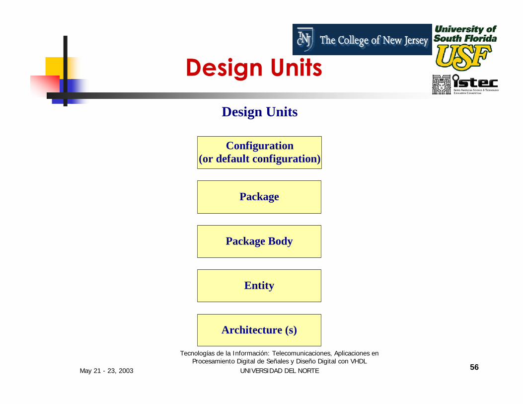
Design units are a concept unique to VHDL that provide advanced configuration management capabilities.
Design units are segments of VHDL code that can compiled separately and stored in a library.
May 21 - 23, 2003
Tecnologías de la Información: Telecomunicaciones, Aplicaciones en Procesamiento Digital de Señales y Diseño Digital con VHDL
UNIVERSIDAD DEL NORTE 56
Configuration(or default configuration)
Package
Package Body
Entity
Architecture (s)
Design Units
Design Units

May 21 - 23, 2003
Tecnologías de la Información: Telecomunicaciones, Aplicaciones en Procesamiento Digital de Señales y Diseño Digital con VHDL
UNIVERSIDAD DEL NORTE 57
Package Design unit
A Package is a collection of commonly used data types to be used globally among different design units.
Package declaration is identified by the package keyword.

May 21 - 23, 2003
Tecnologías de la Información: Telecomunicaciones, Aplicaciones en Procesamiento Digital de Señales y Diseño Digital con VHDL
UNIVERSIDAD DEL NORTE 58
Package Design Unit
Items defined within a package can be made visible to any other design unit in the complete VHDL design and they can be compiled into libraries for later re-use.
A package can consist of two basic parts
A package declarationA package body (optional)
May 21 - 23, 2003
Tecnologías de la Información: Telecomunicaciones, Aplicaciones en Procesamiento Digital de Señales y Diseño Digital con VHDL
UNIVERSIDAD DEL NORTE 59
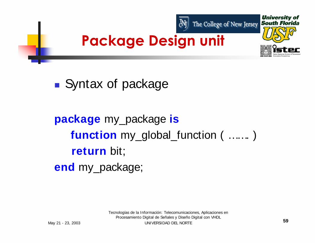
Syntax of package
package my_package isfunction my_global_function ( ……. )return bit;
end my_package;
Package Design unit

May 21 - 23, 2003
Tecnologías de la Información: Telecomunicaciones, Aplicaciones en Procesamiento Digital de Señales y Diseño Digital con VHDL
UNIVERSIDAD DEL NORTE 60
Package Body
The package body defines the actual behavior of the items specified in the package.
The relationship between package and package body is somewhat similar to that of entity and its corresponding architecture.

May 21 - 23, 2003
Tecnologías de la Información: Telecomunicaciones, Aplicaciones en Procesamiento Digital de Señales y Diseño Digital con VHDL
UNIVERSIDAD DEL NORTE 61
VHDL Configurations
VHDL allows you to create more than one alternate architecture for an entity.
This feature helps in experimenting with different implementations of circuit description.
Its also useful for simulation and for project team environments.
May 21 - 23, 2003
Tecnologías de la Información: Telecomunicaciones, Aplicaciones en Procesamiento Digital de Señales y Diseño Digital con VHDL
UNIVERSIDAD DEL NORTE 62
VHDL Configurations
Configuration declarations are not generally used for synthesis, and may not be supported by the synthesis tools.
Configuration declarations are always optional, even for complex circuits.
May 21 - 23, 2003
Tecnologías de la Información: Telecomunicaciones, Aplicaciones en Procesamiento Digital de Señales y Diseño Digital con VHDL
UNIVERSIDAD DEL NORTE 63
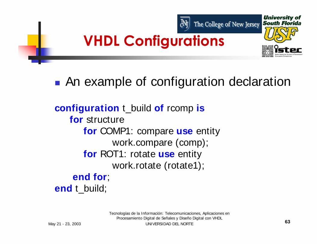
An example of configuration declaration
configuration t_build of rcomp isfor structure
for COMP1: compare use entitywork.compare (comp);
for ROT1: rotate use entitywork.rotate (rotate1);
end for;end t_build;
VHDL Configurations
May 21 - 23, 2003
Tecnologías de la Información: Telecomunicaciones, Aplicaciones en Procesamiento Digital de Señales y Diseño Digital con VHDL
UNIVERSIDAD DEL NORTE 64
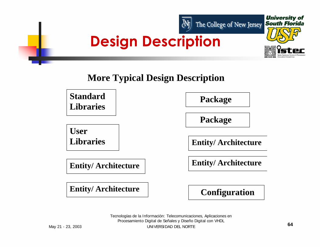
More Typical Design Description
StandardLibraries
UserLibraries
Entity/ Architecture
Entity/ Architecture
Package
Package
Entity/ Architecture
Entity/ Architecture
Configuration
Design Description

May 21 - 23, 2003
Tecnologías de la Información: Telecomunicaciones, Aplicaciones en Procesamiento Digital de Señales y Diseño Digital con VHDL
UNIVERSIDAD DEL NORTE 65
Levels of Abstraction (Styles)
VHDL supports many possible styles of design description.
These styles differ primarily in how closely they relate to the underlying hardware.

May 21 - 23, 2003
Tecnologías de la Información: Telecomunicaciones, Aplicaciones en Procesamiento Digital de Señales y Diseño Digital con VHDL
UNIVERSIDAD DEL NORTE 66
Levels of Abstraction refers to how far your design description is from an actual hardware realization.The three main levels of abstraction are:
BehaviorDataflow (RTL)Structure
Levels of Abstraction (Styles)

May 21 - 23, 2003
Tecnologías de la Información: Telecomunicaciones, Aplicaciones en Procesamiento Digital de Señales y Diseño Digital con VHDL
UNIVERSIDAD DEL NORTE 67
Behavior Dataflow Structure
Performance Specification Test Benches
Sequential Description State Machines
Register Transfers Selected Assignments Arithmetic Operation
Boolean Equations Hierarchy
Physical Information
Levels of Abstraction (Styles)
May 21 - 23, 2003
Tecnologías de la Información: Telecomunicaciones, Aplicaciones en Procesamiento Digital de Señales y Diseño Digital con VHDL
UNIVERSIDAD DEL NORTE 68
Behavioral Modeling
The Highest Level of Abstraction Supported in VHDL .
The Behavior Approach Describes the Actual Behavior of Signals Inside the Component.

May 21 - 23, 2003
Tecnologías de la Información: Telecomunicaciones, Aplicaciones en Procesamiento Digital de Señales y Diseño Digital con VHDL
UNIVERSIDAD DEL NORTE 69
The Concept of Time Is the Critical Distinction Between Behavioral Descriptions and Low Level Descriptions.
The Concept to Time May Be Expressed Precisely, With Actual Delays Between Related Events
VHDL Timing Issues

May 21 - 23, 2003
Tecnologías de la Información: Telecomunicaciones, Aplicaciones en Procesamiento Digital de Señales y Diseño Digital con VHDL
UNIVERSIDAD DEL NORTE 70
An Example of Behavioral Modeling: A half adder
carry
suma
b

May 21 - 23, 2003
Tecnologías de la Información: Telecomunicaciones, Aplicaciones en Procesamiento Digital de Señales y Diseño Digital con VHDL
UNIVERSIDAD DEL NORTE 71
half_adder
Half_adderInputs a, b : 1 bit each.Output Sum, Carry : 1 bit each.
sum
carry
a
b
Figure 1-1 Half adder circuit
May 21 - 23, 2003
Tecnologías de la Información: Telecomunicaciones, Aplicaciones en Procesamiento Digital de Señales y Diseño Digital con VHDL
UNIVERSIDAD DEL NORTE 72
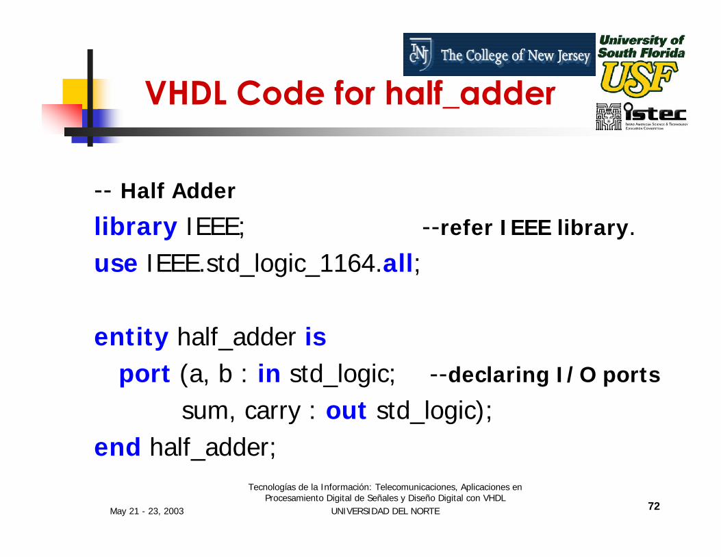
VHDL Code for half_adder
-- Half Adder
library IEEE; --refer IEEE library.use IEEE.std_logic_1164.all;
entity half_adder isport (a, b : in std_logic; --declaring I/O ports
sum, carry : out std_logic);end half_adder;

May 21 - 23, 2003
Tecnologías de la Información: Telecomunicaciones, Aplicaciones en Procesamiento Digital de Señales y Diseño Digital con VHDL
UNIVERSIDAD DEL NORTE 73
half_adder code (cont…)
architecture behavior ofhalf_adder is
beginsum <= (a xor b);carry <= (a and b);
end behavior;
sum
carry
a
b
Figure 1-1 Half adder circuit
May 21 - 23, 2003
Tecnologías de la Información: Telecomunicaciones, Aplicaciones en Procesamiento Digital de Señales y Diseño Digital con VHDL
UNIVERSIDAD DEL NORTE 74
Max+Plus II Development Software
MAX+PLUS II is a Development software created by ALTERA This software supports schematic capture and text-based hardware description language (HDL) design entry, including Verilog® HDL, VHDL, and the Altera® Hardware Description Language (AHDLTM)
May 21 - 23, 2003
Tecnologías de la Información: Telecomunicaciones, Aplicaciones en Procesamiento Digital de Señales y Diseño Digital con VHDL
UNIVERSIDAD DEL NORTE 75
Max+Plus II Development Software
It also provides design programming, compilation, and verification support for all devices supported by the MAX+PLUS II BASELINE software including the EPM7128S, EPF10K20, and EPF10K70 devices
May 21 - 23, 2003
Tecnologías de la Información: Telecomunicaciones, Aplicaciones en Procesamiento Digital de Señales y Diseño Digital con VHDL
UNIVERSIDAD DEL NORTE 76
Max+Plus II Development Software
The MAX+PLUS II University software can be freely distributed to students for installation on their personal computers and provides instant access to online help. For more information, follow the University Program Link at www.altera.com
May 21 - 23, 2003
Tecnologías de la Información: Telecomunicaciones, Aplicaciones en Procesamiento Digital de Señales y Diseño Digital con VHDL
UNIVERSIDAD DEL NORTE 77
Max+Plus II Development Software
This Tool was created to help during the various implementation steps:
DesignGraphical EntryVHDL Model
CompilationSimulationVerificationSynthesis
May 21 - 23, 2003
Tecnologías de la Información: Telecomunicaciones, Aplicaciones en Procesamiento Digital de Señales y Diseño Digital con VHDL
UNIVERSIDAD DEL NORTE 78
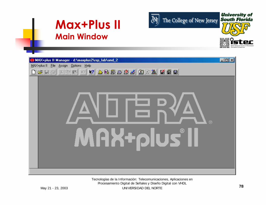
Max+Plus II Main Window

May 21 - 23, 2003
Tecnologías de la Información: Telecomunicaciones, Aplicaciones en Procesamiento Digital de Señales y Diseño Digital con VHDL
UNIVERSIDAD DEL NORTE 79
Max+Plus II 1st Part of The Process !!!!
Design
Graphical Entry
HDL Model
Compilation
Compiler
May 21 - 23, 2003
Tecnologías de la Información: Telecomunicaciones, Aplicaciones en Procesamiento Digital de Señales y Diseño Digital con VHDL
UNIVERSIDAD DEL NORTE 80
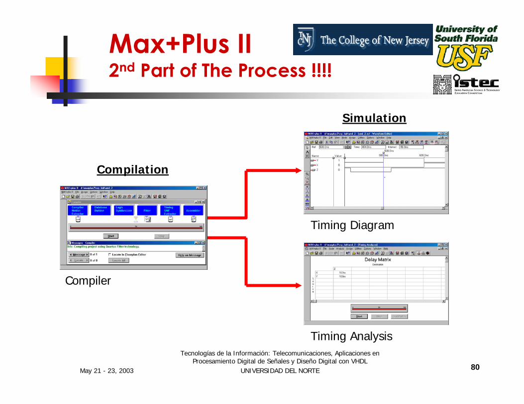
Max+Plus II 2nd Part of The Process !!!!
Compilation
Compiler
Simulation
Timing Diagram
Timing Analysis

May 21 - 23, 2003
Tecnologías de la Información: Telecomunicaciones, Aplicaciones en Procesamiento Digital de Señales y Diseño Digital con VHDL
UNIVERSIDAD DEL NORTE 81
Max+Plus II 3rd Part of The Process !!!!
Compilation
Compiler
Verification
Programming
UP1 Board
May 21 - 23, 2003
Tecnologías de la Información: Telecomunicaciones, Aplicaciones en Procesamiento Digital de Señales y Diseño Digital con VHDL
UNIVERSIDAD DEL NORTE 82
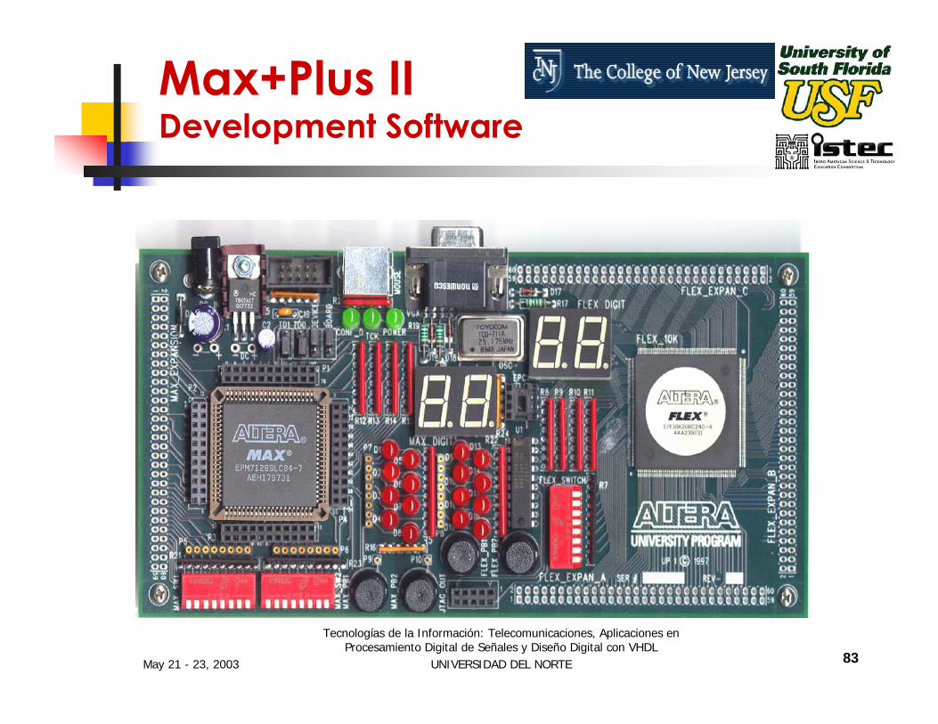
Max+Plus II Development Software
MAX+PLUS II University software targets the UP1 and UP1X development boards.the FLEX10K and MAX7000S devices can be configured and programmed (respectively) to interact with the included hardware or with any other external design.
May 21 - 23, 2003
Tecnologías de la Información: Telecomunicaciones, Aplicaciones en Procesamiento Digital de Señales y Diseño Digital con VHDL
UNIVERSIDAD DEL NORTE 83
Max+Plus II Development Software
May 21 - 23, 2003
Tecnologías de la Información: Telecomunicaciones, Aplicaciones en Procesamiento Digital de Señales y Diseño Digital con VHDL
UNIVERSIDAD DEL NORTE 84
Max+Plus II Half-Adder
We will use our previous Half-Adder model as an example of how to perform a VHDL code entry.
May 21 - 23, 2003
Tecnologías de la Información: Telecomunicaciones, Aplicaciones en Procesamiento Digital de Señales y Diseño Digital con VHDL
UNIVERSIDAD DEL NORTE 85
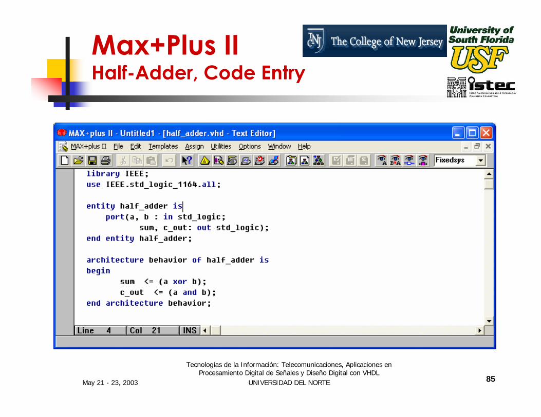
Max+Plus II Half-Adder, Code Entry
May 21 - 23, 2003
Tecnologías de la Información: Telecomunicaciones, Aplicaciones en Procesamiento Digital de Señales y Diseño Digital con VHDL
UNIVERSIDAD DEL NORTE 86
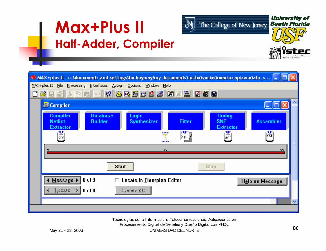
Max+Plus II Half-Adder, Compiler
May 21 - 23, 2003
Tecnologías de la Información: Telecomunicaciones, Aplicaciones en Procesamiento Digital de Señales y Diseño Digital con VHDL
UNIVERSIDAD DEL NORTE 87
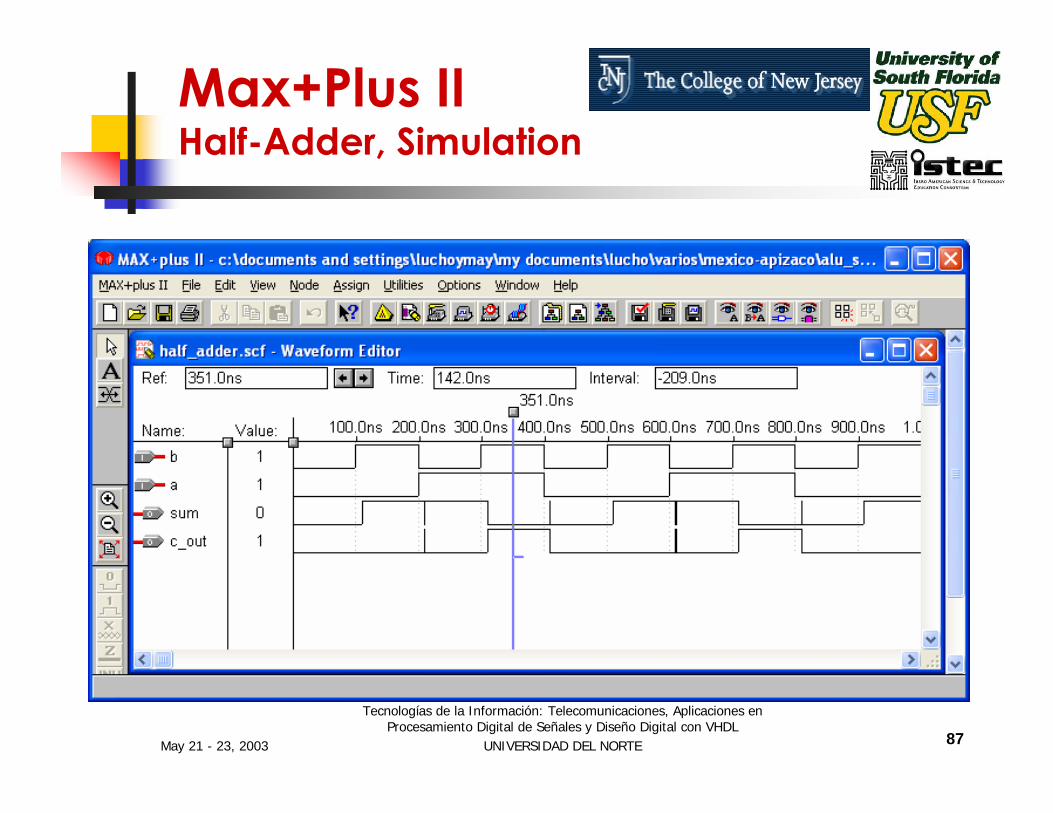
Max+Plus II Half-Adder, Simulation

May 21 - 23, 2003
Tecnologías de la Información: Telecomunicaciones, Aplicaciones en Procesamiento Digital de Señales y Diseño Digital con VHDL
UNIVERSIDAD DEL NORTE 88
Session II
INTRODUCTION TO VHDL – PART II
May 21 - 23, 2003
Tecnologías de la Información: Telecomunicaciones, Aplicaciones en Procesamiento Digital de Señales y Diseño Digital con VHDL
UNIVERSIDAD DEL NORTE 89
The dataflow level of abstraction is often called Register Transfer Language (RTL).
The dataflow level of abstraction describes how information is passed between registers in the circuit.
Dataflow (RTL) Modeling

May 21 - 23, 2003
Tecnologías de la Información: Telecomunicaciones, Aplicaciones en Procesamiento Digital de Señales y Diseño Digital con VHDL
UNIVERSIDAD DEL NORTE 90
Concurrent and Sequential VHDL
VHDL Allows Both Concurrent and Sequential Statements to Be Entered.
The Difference Between Concurrent and Sequential Statements Must Be Known for Effective Use of the Language.

May 21 - 23, 2003
Tecnologías de la Información: Telecomunicaciones, Aplicaciones en Procesamiento Digital de Señales y Diseño Digital con VHDL
UNIVERSIDAD DEL NORTE 91
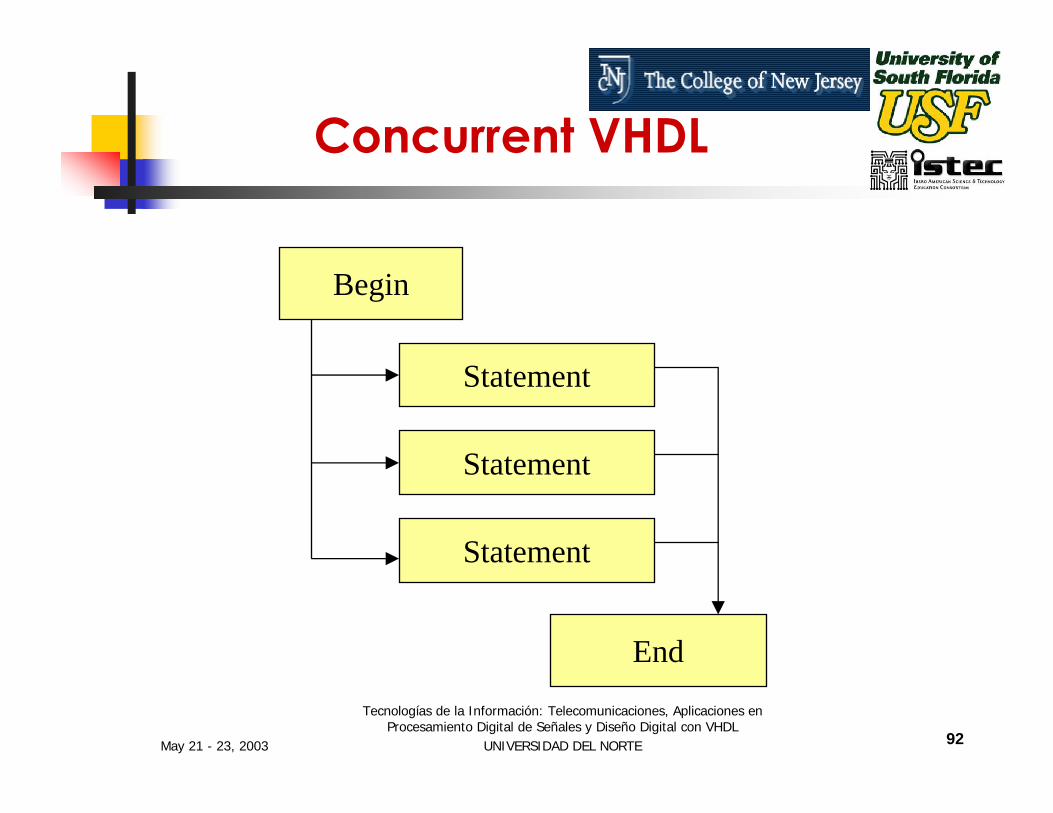
Concurrent VHDL
All Statements in the Concurrent Area Are Executed at the Same Time.
There Is No Significance to the Order in Which Concurrent Statements Occur.
May 21 - 23, 2003
Tecnologías de la Información: Telecomunicaciones, Aplicaciones en Procesamiento Digital de Señales y Diseño Digital con VHDL
UNIVERSIDAD DEL NORTE 92
Begin
Statement
Statement
Statement
End
Concurrent VHDL

May 21 - 23, 2003
Tecnologías de la Información: Telecomunicaciones, Aplicaciones en Procesamiento Digital de Señales y Diseño Digital con VHDL
UNIVERSIDAD DEL NORTE 93
Example of Concurrent VHDL
Full Adder
aSum
bC_out
C_in
Full-Adder
May 21 - 23, 2003
Tecnologías de la Información: Telecomunicaciones, Aplicaciones en Procesamiento Digital de Señales y Diseño Digital con VHDL
UNIVERSIDAD DEL NORTE 94
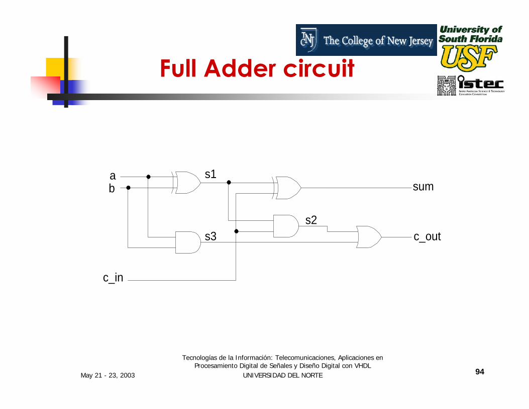
Full Adder circuit
ab
c_in
sum
c_out
s1
s3s2
May 21 - 23, 2003
Tecnologías de la Información: Telecomunicaciones, Aplicaciones en Procesamiento Digital de Señales y Diseño Digital con VHDL
UNIVERSIDAD DEL NORTE 95
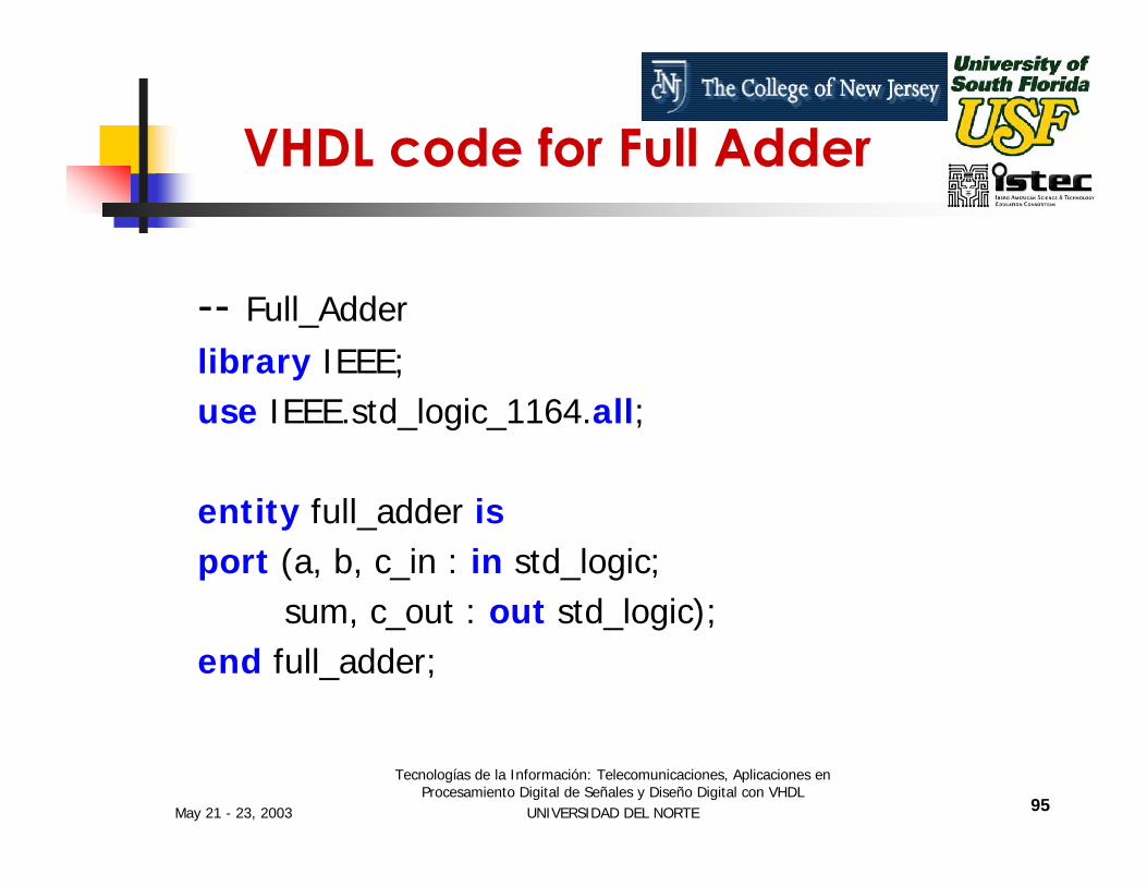
VHDL code for Full Adder
-- Full_Adderlibrary IEEE;use IEEE.std_logic_1164.all;
entity full_adder isport (a, b, c_in : in std_logic;
sum, c_out : out std_logic);end full_adder;

May 21 - 23, 2003
Tecnologías de la Información: Telecomunicaciones, Aplicaciones en Procesamiento Digital de Señales y Diseño Digital con VHDL
UNIVERSIDAD DEL NORTE 96
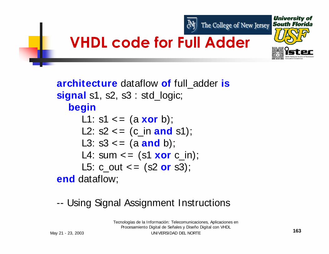
architecture dataflow of full_adder issignal s1, s2, s3 : std_logic;
beginL1: s1 <= (a xor b);L2: s2 <= (c_in and s1);L3: s3 <= (a and b);L4: sum <= (s1 xor c_in);L5: c_out <= (s2 or s3);
end dataflow;
-- Using Signal Assignment Instructions
VHDL code for Full Adder

May 21 - 23, 2003
Tecnologías de la Información: Telecomunicaciones, Aplicaciones en Procesamiento Digital de Señales y Diseño Digital con VHDL
UNIVERSIDAD DEL NORTE 97
Max+Plus II Full-Adder
Next we will use MAX+PLUS II to Compile and Simulate our previous Full-Adder model.

May 21 - 23, 2003
Tecnologías de la Información: Telecomunicaciones, Aplicaciones en Procesamiento Digital de Señales y Diseño Digital con VHDL
UNIVERSIDAD DEL NORTE 98
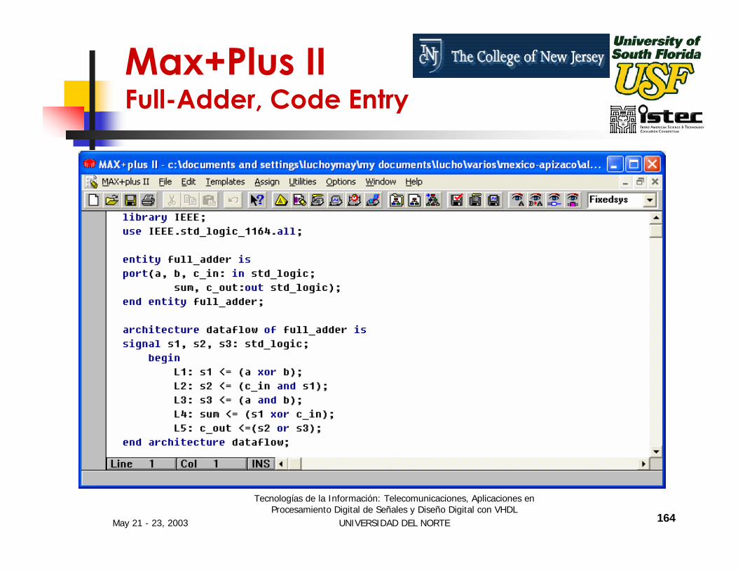
Max+Plus II Full-Adder, Code Entry

May 21 - 23, 2003
Tecnologías de la Información: Telecomunicaciones, Aplicaciones en Procesamiento Digital de Señales y Diseño Digital con VHDL
UNIVERSIDAD DEL NORTE 99
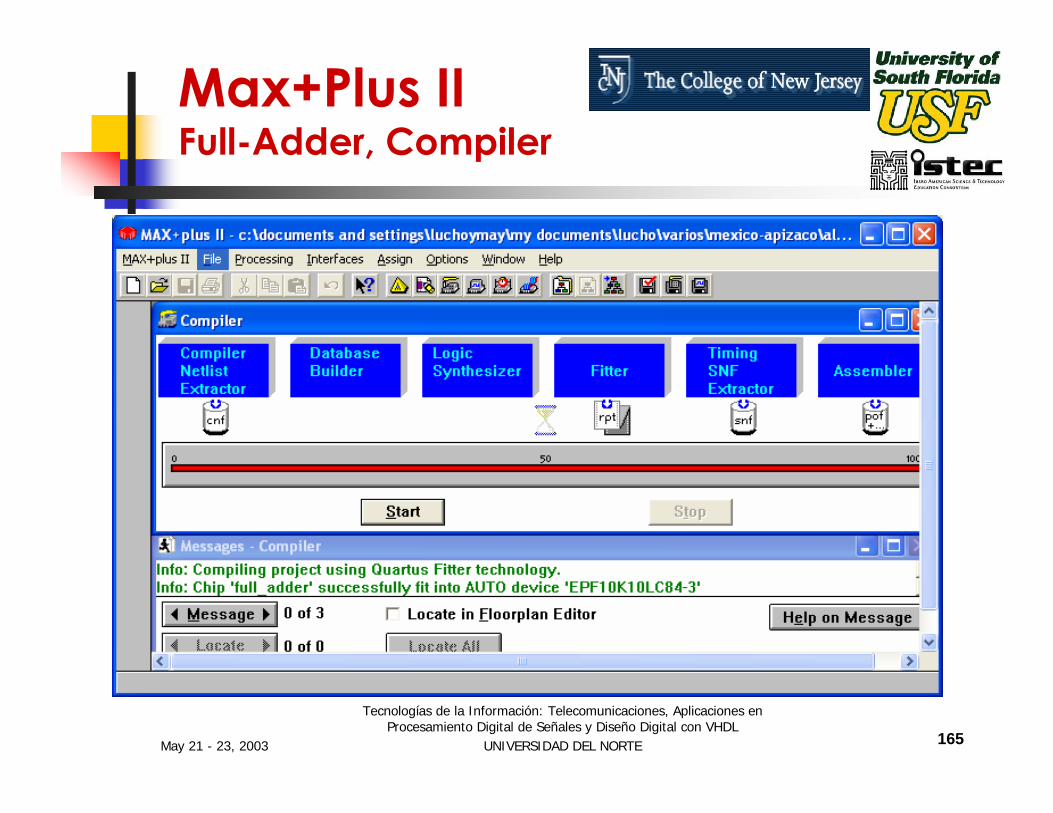
Max+Plus II Full-Adder, Compiler
May 21 - 23, 2003
Tecnologías de la Información: Telecomunicaciones, Aplicaciones en Procesamiento Digital de Señales y Diseño Digital con VHDL
UNIVERSIDAD DEL NORTE 100
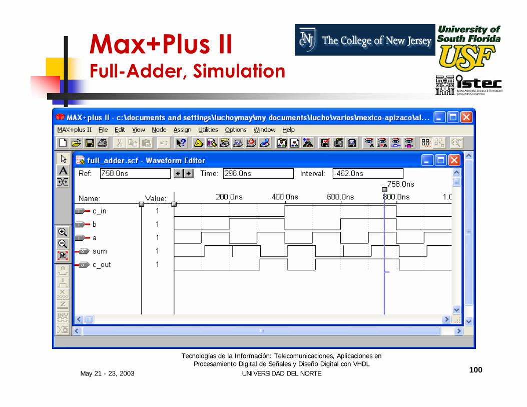
Max+Plus II Full-Adder, Simulation
May 21 - 23, 2003
Tecnologías de la Información: Telecomunicaciones, Aplicaciones en Procesamiento Digital de Señales y Diseño Digital con VHDL
UNIVERSIDAD DEL NORTE 101
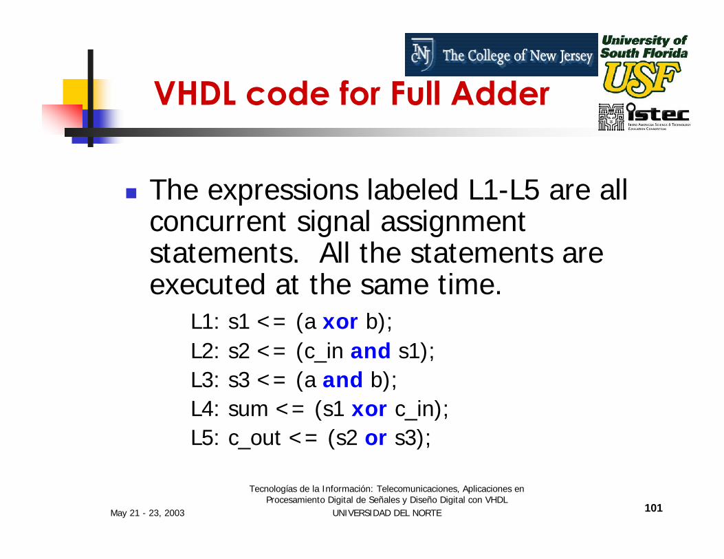
VHDL code for Full Adder
The expressions labeled L1-L5 are all concurrent signal assignment statements. All the statements are executed at the same time.
L1: s1 <= (a xor b);L2: s2 <= (c_in and s1);L3: s3 <= (a and b);L4: sum <= (s1 xor c_in);L5: c_out <= (s2 or s3);
May 21 - 23, 2003
Tecnologías de la Información: Telecomunicaciones, Aplicaciones en Procesamiento Digital de Señales y Diseño Digital con VHDL
UNIVERSIDAD DEL NORTE 102
VHDL code for Full Adder
The simulator evaluates all the expressions, L1-L5, then applies the results to the signals.
Once the simulator has applied the results it waits for one of the signal to change and it reevaluates all the expression again.

May 21 - 23, 2003
Tecnologías de la Información: Telecomunicaciones, Aplicaciones en Procesamiento Digital de Señales y Diseño Digital con VHDL
UNIVERSIDAD DEL NORTE 103
VHDL code for Full Adder
This cycle will continue until the simulation is completed.
This is called “event driven simulation”.
It is more computationally efficient than time driven simulation.

May 21 - 23, 2003
Tecnologías de la Información: Telecomunicaciones, Aplicaciones en Procesamiento Digital de Señales y Diseño Digital con VHDL
UNIVERSIDAD DEL NORTE 104
Signals
In the Full_adder VHDL code we came across “signal”.
architecture dataflow of full_adder issignal s1, s2, s3: std_logic;
begin
………end dataflow;
So what are “signals”?

May 21 - 23, 2003
Tecnologías de la Información: Telecomunicaciones, Aplicaciones en Procesamiento Digital de Señales y Diseño Digital con VHDL
UNIVERSIDAD DEL NORTE 105
Signals
Signals Are Used to Carry Data From Place to Place in a VHDL Design Description.
Signals Are Similar to Wires in a Schematic.
Signals are internal to an entity, so they exist only in the architectures.
May 21 - 23, 2003
Tecnologías de la Información: Telecomunicaciones, Aplicaciones en Procesamiento Digital de Señales y Diseño Digital con VHDL
UNIVERSIDAD DEL NORTE 106
Sequential VHDL
Sequential Statements Are Executed One After the Other in the Order That They Appear.
Example of Sequential Statement: Process.
May 21 - 23, 2003
Tecnologías de la Información: Telecomunicaciones, Aplicaciones en Procesamiento Digital de Señales y Diseño Digital con VHDL
UNIVERSIDAD DEL NORTE 107
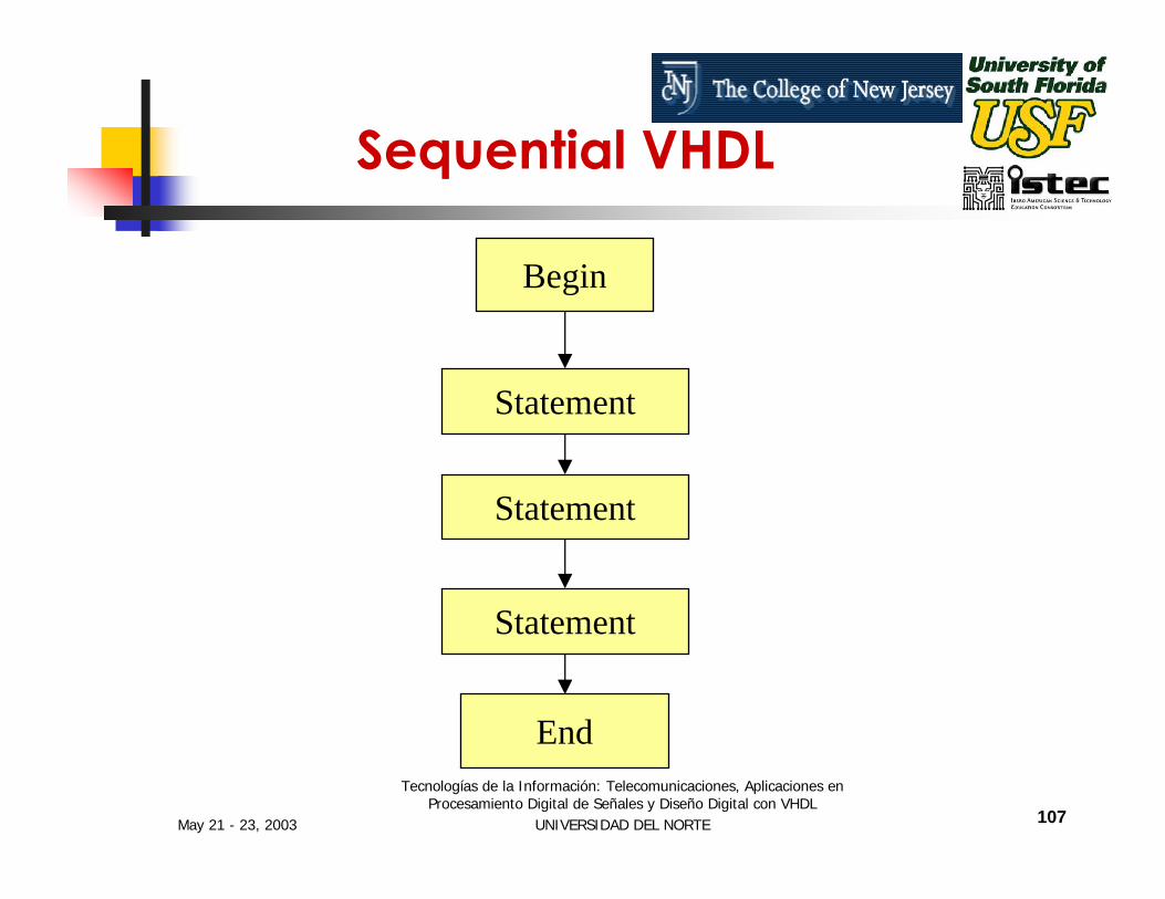
Begin
Statement
Statement
Statement
End
Sequential VHDL

May 21 - 23, 2003
Tecnologías de la Información: Telecomunicaciones, Aplicaciones en Procesamiento Digital de Señales y Diseño Digital con VHDL
UNIVERSIDAD DEL NORTE 108
Process Construct
The Process construct is the primary means to describe sequential operations.
Process starts with the keyword process and ends with the keyword end process.
The process construct itself is treated as a concurrent statement.

May 21 - 23, 2003
Tecnologías de la Información: Telecomunicaciones, Aplicaciones en Procesamiento Digital de Señales y Diseño Digital con VHDL
UNIVERSIDAD DEL NORTE 109
The process consists of three parts
Sensitivity ListProcess declaration partStatement Part
Process Statement

May 21 - 23, 2003
Tecnologías de la Información: Telecomunicaciones, Aplicaciones en Procesamiento Digital de Señales y Diseño Digital con VHDL
UNIVERSIDAD DEL NORTE 110
architecture arch_name of ent_name isbeginprocess_name: process (sensitivity_list)
local_declaration;…….beginsequential statement;sequential statement;…..end process;
end arch_name;
Syntax of Process Statement

May 21 - 23, 2003
Tecnologías de la Información: Telecomunicaciones, Aplicaciones en Procesamiento Digital de Señales y Diseño Digital con VHDL
UNIVERSIDAD DEL NORTE 111
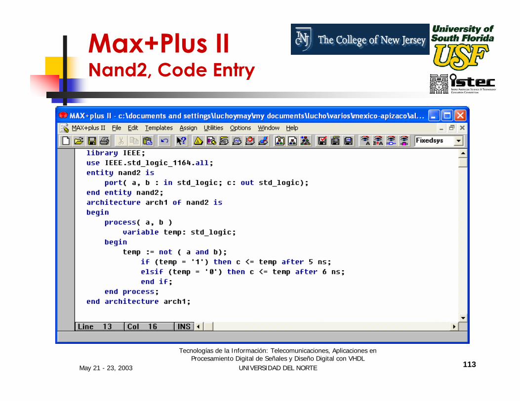
library IEEE;use IEEE.std_logic_1164.all;entity nand2 is
port (a, b : in std_logic;c : out std_logic);
end nand2;architecture arch1 of nand2 is
beginprocess (a, b)variable temp: std_logic;
Process Example

May 21 - 23, 2003
Tecnologías de la Información: Telecomunicaciones, Aplicaciones en Procesamiento Digital de Señales y Diseño Digital con VHDL
UNIVERSIDAD DEL NORTE 112
begintemp = not (a and b);if (temp = ‘1’) then
c <= temp after 5 ns;elseif (temp = ‘0’) then
c <= temp after 6 ns;end if;
end process;end arch;
Process Example
May 21 - 23, 2003
Tecnologías de la Información: Telecomunicaciones, Aplicaciones en Procesamiento Digital de Señales y Diseño Digital con VHDL
UNIVERSIDAD DEL NORTE 113
Max+Plus II Nand2, Code Entry

May 21 - 23, 2003
Tecnologías de la Información: Telecomunicaciones, Aplicaciones en Procesamiento Digital de Señales y Diseño Digital con VHDL
UNIVERSIDAD DEL NORTE 114
Max+Plus II Nand2, Compiler
May 21 - 23, 2003
Tecnologías de la Información: Telecomunicaciones, Aplicaciones en Procesamiento Digital de Señales y Diseño Digital con VHDL
UNIVERSIDAD DEL NORTE 115
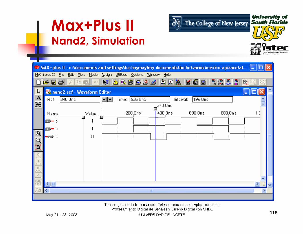
Max+Plus II Nand2, Simulation

May 21 - 23, 2003
Tecnologías de la Información: Telecomunicaciones, Aplicaciones en Procesamiento Digital de Señales y Diseño Digital con VHDL
UNIVERSIDAD DEL NORTE 116
library IEEE;use IEEE.std_logic.all
Example Description
library and use statements allowing to use the IEEE 1164 standard logic data types.
May 21 - 23, 2003
Tecnologías de la Información: Telecomunicaciones, Aplicaciones en Procesamiento Digital de Señales y Diseño Digital con VHDL
UNIVERSIDAD DEL NORTE 117
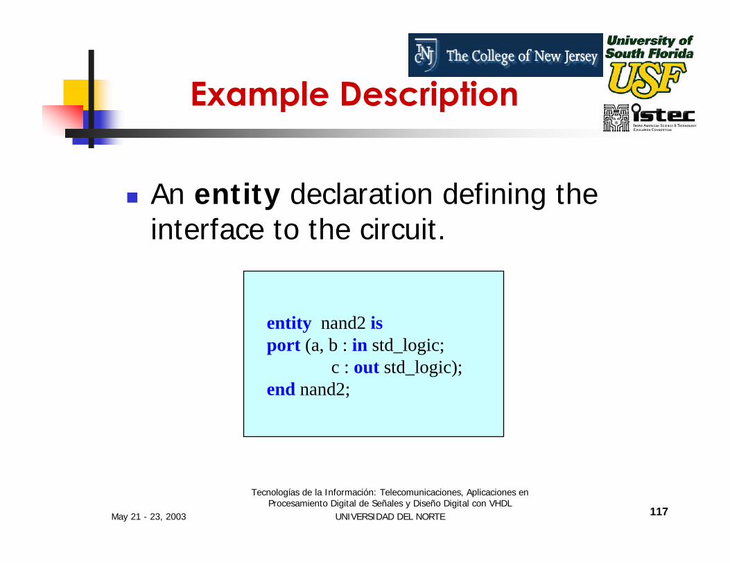
entity nand2 isport (a, b : in std_logic;
c : out std_logic);end nand2;
Example Description
An entity declaration defining the interface to the circuit.

May 21 - 23, 2003
Tecnologías de la Información: Telecomunicaciones, Aplicaciones en Procesamiento Digital de Señales y Diseño Digital con VHDL
UNIVERSIDAD DEL NORTE 118
Example Description
The process sensitivity list enumerates exactly which signals causes the process execution.
process (a, b)
May 21 - 23, 2003
Tecnologías de la Información: Telecomunicaciones, Aplicaciones en Procesamiento Digital de Señales y Diseño Digital con VHDL
UNIVERSIDAD DEL NORTE 119
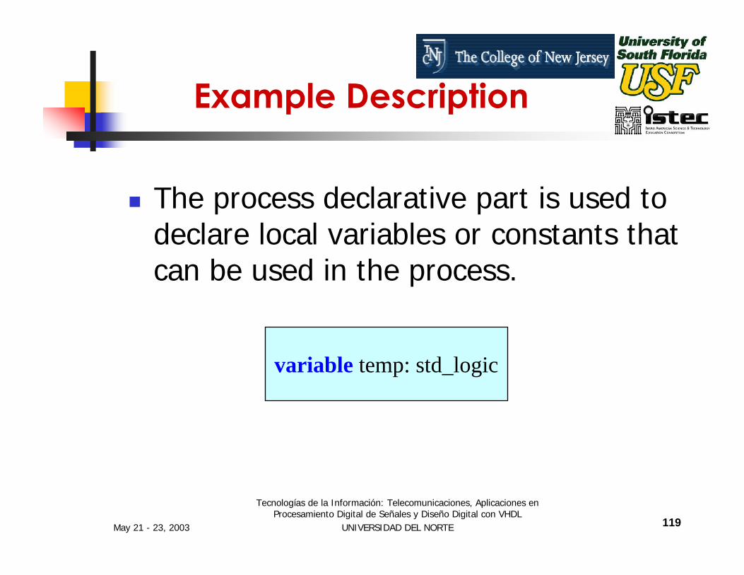
variable temp: std_logic
Example Description
The process declarative part is used to declare local variables or constants that can be used in the process.

May 21 - 23, 2003
Tecnologías de la Información: Telecomunicaciones, Aplicaciones en Procesamiento Digital de Señales y Diseño Digital con VHDL
UNIVERSIDAD DEL NORTE 120
variable temp: std_logic
Variables are temporary storage areas similar to variables in software programming languages.
Example Description

May 21 - 23, 2003
Tecnologías de la Información: Telecomunicaciones, Aplicaciones en Procesamiento Digital de Señales y Diseño Digital con VHDL
UNIVERSIDAD DEL NORTE 121
Use of Sequential Statements
Sequential Statements Exist Inside the Process Statements As Well As in Sub Programs.
The Sequential Statements Are:if case loopassert wait

May 21 - 23, 2003
Tecnologías de la Información: Telecomunicaciones, Aplicaciones en Procesamiento Digital de Señales y Diseño Digital con VHDL
UNIVERSIDAD DEL NORTE 122
IF Statements
If (x < 10) thena := b;
end if;
The IF statement starts with the keyword if and ends with the keyword end if.

May 21 - 23, 2003
Tecnologías de la Información: Telecomunicaciones, Aplicaciones en Procesamiento Digital de Señales y Diseño Digital con VHDL
UNIVERSIDAD DEL NORTE 123
IF Statements
There are also two optional clauses
Elsif clauseElse clause
if (day = Sunday) thenweekend := true;
elsif (day = Saturday) thenweekend := true;
else weekday := true;
end if;

May 21 - 23, 2003
Tecnologías de la Información: Telecomunicaciones, Aplicaciones en Procesamiento Digital de Señales y Diseño Digital con VHDL
UNIVERSIDAD DEL NORTE 124
The if statement can have multiple elsif statement parts but only one else statement part.
IF Statements

May 21 - 23, 2003
Tecnologías de la Información: Telecomunicaciones, Aplicaciones en Procesamiento Digital de Señales y Diseño Digital con VHDL
UNIVERSIDAD DEL NORTE 125
Case statement
The Case statement is used whenever a single expression value can be used to select between a number of actions.
A Case statement consists of the keyword case followed by an expression and the keyword is.
May 21 - 23, 2003
Tecnologías de la Información: Telecomunicaciones, Aplicaciones en Procesamiento Digital de Señales y Diseño Digital con VHDL
UNIVERSIDAD DEL NORTE 126
Case statement
The expression will either return a value that matches one of the choices in a when statement part or match an others clause.
May 21 - 23, 2003
Tecnologías de la Información: Telecomunicaciones, Aplicaciones en Procesamiento Digital de Señales y Diseño Digital con VHDL
UNIVERSIDAD DEL NORTE 127
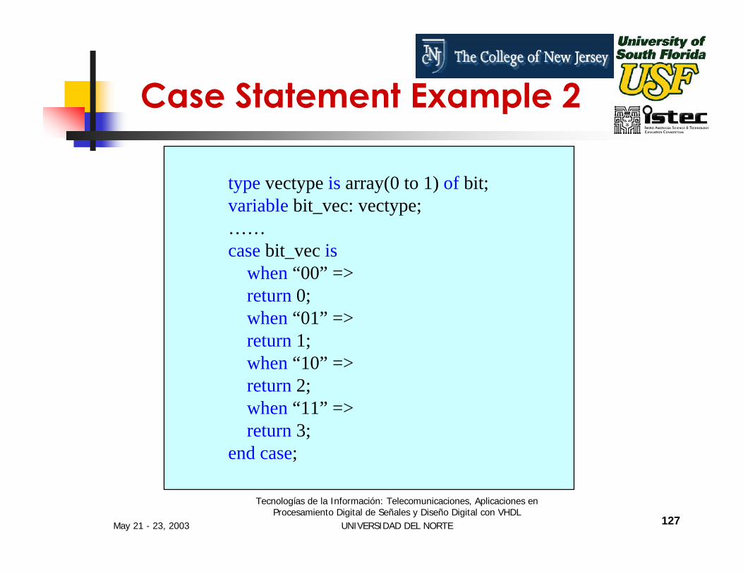
type vectype is array(0 to 1) of bit;variable bit_vec: vectype;……case bit_vec is
when “00” =>return 0;when “01” =>return 1;when “10” =>return 2;when “11” =>return 3;
end case;
Case Statement Example 2
May 21 - 23, 2003
Tecnologías de la Información: Telecomunicaciones, Aplicaciones en Procesamiento Digital de Señales y Diseño Digital con VHDL
UNIVERSIDAD DEL NORTE 128
The loop statement is used whenever an operation needs to be repeated.
Loop statements are implemented in two ways
while condition loop statementfor condition loop statement
Loop Statements
May 21 - 23, 2003
Tecnologías de la Información: Telecomunicaciones, Aplicaciones en Procesamiento Digital de Señales y Diseño Digital con VHDL
UNIVERSIDAD DEL NORTE 129
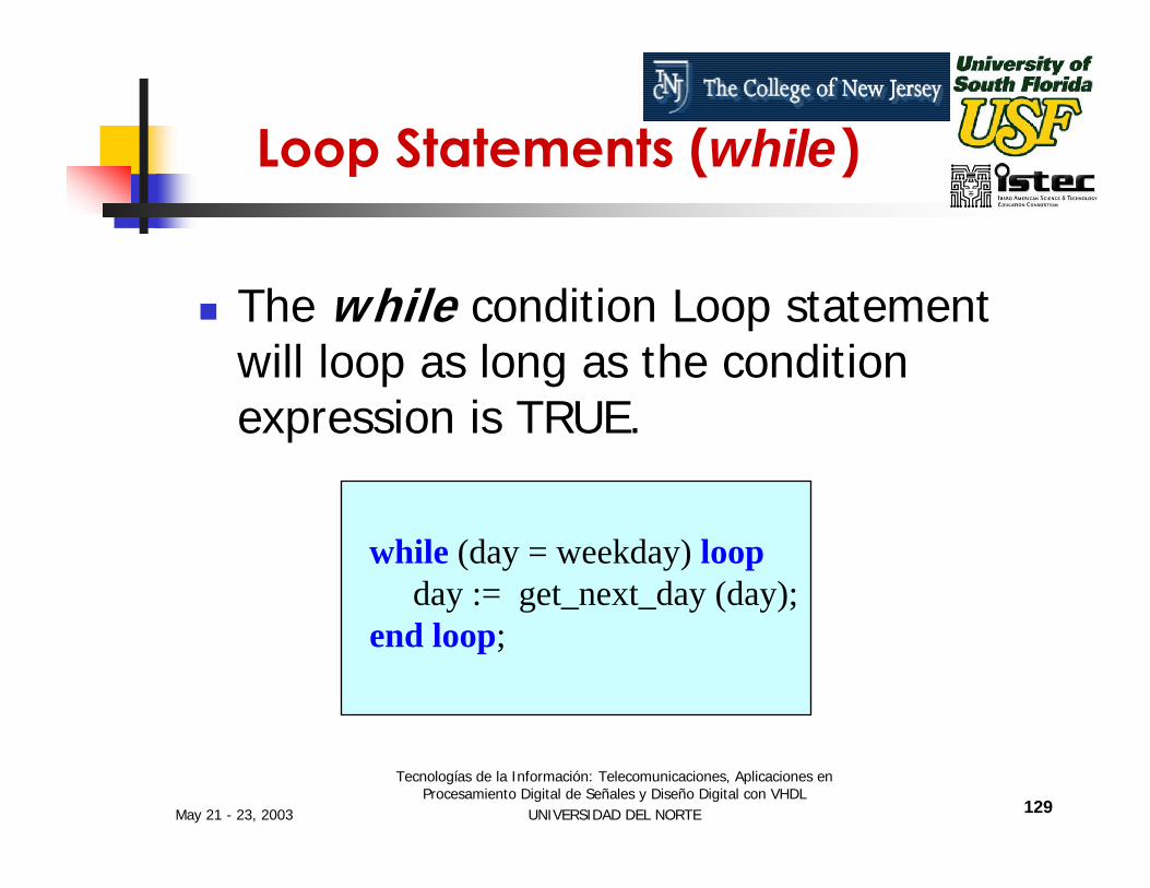
while (day = weekday) loopday := get_next_day (day);
end loop;
Loop Statements (while)
The while condition Loop statement will loop as long as the condition expression is TRUE.

May 21 - 23, 2003
Tecnologías de la Información: Telecomunicaciones, Aplicaciones en Procesamiento Digital de Señales y Diseño Digital con VHDL
UNIVERSIDAD DEL NORTE 130
for i in 1 to 10 loopi_squared(i) := i*i;
end loop;
Loop Statements (for loop)
This loop will execute 10 times whenever execution begins and its function is to calculate squares from 1 to 10 and insert them into i_squared signal array.
May 21 - 23, 2003
Tecnologías de la Información: Telecomunicaciones, Aplicaciones en Procesamiento Digital de Señales y Diseño Digital con VHDL
UNIVERSIDAD DEL NORTE 131
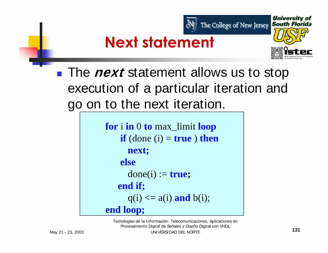
for i in 0 to max_limit loopif (done (i) = true ) then
next;else
done(i) := true;end if;
q(i) <= a(i) and b(i);end loop;
Next statement
The next statement allows us to stop execution of a particular iteration and go on to the next iteration.
May 21 - 23, 2003
Tecnologías de la Información: Telecomunicaciones, Aplicaciones en Procesamiento Digital de Señales y Diseño Digital con VHDL
UNIVERSIDAD DEL NORTE 132
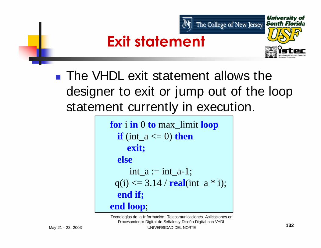
for i in 0 to max_limit loopif (int_a <= 0) then
exit;else
int_a := int_a-1;q(i) <= 3.14 / real(int_a * i);end if;
end loop;
Exit statement
The VHDL exit statement allows the designer to exit or jump out of the loop statement currently in execution.
May 21 - 23, 2003
Tecnologías de la Información: Telecomunicaciones, Aplicaciones en Procesamiento Digital de Señales y Diseño Digital con VHDL
UNIVERSIDAD DEL NORTE 133
Assert Statement
Assert Statements Are Very Useful for Reporting Textual Strings to the Designer.
The Assert Statement Checks the Value of a Boolean Expression. If the Condition Is Not True, a Report (Message) Is Generated During the Simulation.
May 21 - 23, 2003
Tecnologías de la Información: Telecomunicaciones, Aplicaciones en Procesamiento Digital de Señales y Diseño Digital con VHDL
UNIVERSIDAD DEL NORTE 134
Assert Statement
An assert statement includes two options, either or both of which may be used. The first Option
Report: displays a user defined message if the condition is false
May 21 - 23, 2003
Tecnologías de la Información: Telecomunicaciones, Aplicaciones en Procesamiento Digital de Señales y Diseño Digital con VHDL
UNIVERSIDAD DEL NORTE 135
Assert Statement
An assert statement includes two options, either or both of which may be used. The second Option:
Severity: allows the user to choose a severity level if the condition is false. The four levels of severity are
Note, Warning, Error Failure
May 21 - 23, 2003
Tecnologías de la Información: Telecomunicaciones, Aplicaciones en Procesamiento Digital de Señales y Diseño Digital con VHDL
UNIVERSIDAD DEL NORTE 136
Wait Statements
The wait statement allows to suspend the sequential execution of a process or subprogram.
The condition for resuming execution of the suspended process or subprogram can be specified by three different means.

May 21 - 23, 2003
Tecnologías de la Información: Telecomunicaciones, Aplicaciones en Procesamiento Digital de Señales y Diseño Digital con VHDL
UNIVERSIDAD DEL NORTE 137
wait on signal [signal]
wait until Boolean_expression
Wait Statements
wait on signal changes.
wait until an expression is true.
May 21 - 23, 2003
Tecnologías de la Información: Telecomunicaciones, Aplicaciones en Procesamiento Digital de Señales y Diseño Digital con VHDL
UNIVERSIDAD DEL NORTE 138
wait for time_expression
Wait Statements
wait for a specific amount time.

May 21 - 23, 2003
Tecnologías de la Información: Telecomunicaciones, Aplicaciones en Procesamiento Digital de Señales y Diseño Digital con VHDL
UNIVERSIDAD DEL NORTE 139
Wait on Statement
process begin
if (reset = ‘1’ ) then q <= ‘0’ ;
elsif clock ‘event and clock = ‘1’ thenq <= d;
end if; wait on reset, clock;
end process;
The wait on signal clause specifies a list of one or more signals upon which the wait statement will wait for the events.

May 21 - 23, 2003
Tecnologías de la Información: Telecomunicaciones, Aplicaciones en Procesamiento Digital de Señales y Diseño Digital con VHDL
UNIVERSIDAD DEL NORTE 140
Wait Until Statement
processbegin
wait until clock = ‘1’ and clock’ event;q <= d ;
end process;
The wait until Boolean_expression clause will suspend execution of the process until the expression returns a true value.
May 21 - 23, 2003
Tecnologías de la Información: Telecomunicaciones, Aplicaciones en Procesamiento Digital de Señales y Diseño Digital con VHDL
UNIVERSIDAD DEL NORTE 141
Wait for Statement
wait for 10 ns;
The wait for time_expression clause will suspend execution of the process for the time specified by the time expression.
The wait statement will suspend for 10 ns and after 10 ns the execution will continue.
May 21 - 23, 2003
Tecnologías de la Información: Telecomunicaciones, Aplicaciones en Procesamiento Digital de Señales y Diseño Digital con VHDL
UNIVERSIDAD DEL NORTE 142
Structural VHDL
Structural-level design methods can be useful for managing the complexity of a large design description.
Structure level of abstraction is used to combine multiple components to form a larger circuit.
May 21 - 23, 2003
Tecnologías de la Información: Telecomunicaciones, Aplicaciones en Procesamiento Digital de Señales y Diseño Digital con VHDL
UNIVERSIDAD DEL NORTE 143
Structural VHDL Descriptions Are Quite Similar in Format to Schematic Netlists.
Larger Circuits Can Be Constructed From Smaller Building Blocks.
Structural VHDL

May 21 - 23, 2003
Tecnologías de la Información: Telecomunicaciones, Aplicaciones en Procesamiento Digital de Señales y Diseño Digital con VHDL
UNIVERSIDAD DEL NORTE 144
Example of Structural VHDL
Let us consider an ALU withAn OR gateAn XOR gateA Half AdderA Full AdderA Multiplexer

May 21 - 23, 2003
Tecnologías de la Información: Telecomunicaciones, Aplicaciones en Procesamiento Digital de Señales y Diseño Digital con VHDL
UNIVERSIDAD DEL NORTE 145
ALU
Example of Structural VHDL
OR gate
XORgate
Half Adder
FullAdder Mux

May 21 - 23, 2003
Tecnologías de la Información: Telecomunicaciones, Aplicaciones en Procesamiento Digital de Señales y Diseño Digital con VHDL
UNIVERSIDAD DEL NORTE 146
a b
c_in
Z
C_out
s1 s0
4 to 1muxhalf
adder
fulladder
ALU – Block Diagram
May 21 - 23, 2003
Tecnologías de la Información: Telecomunicaciones, Aplicaciones en Procesamiento Digital de Señales y Diseño Digital con VHDL
UNIVERSIDAD DEL NORTE 147
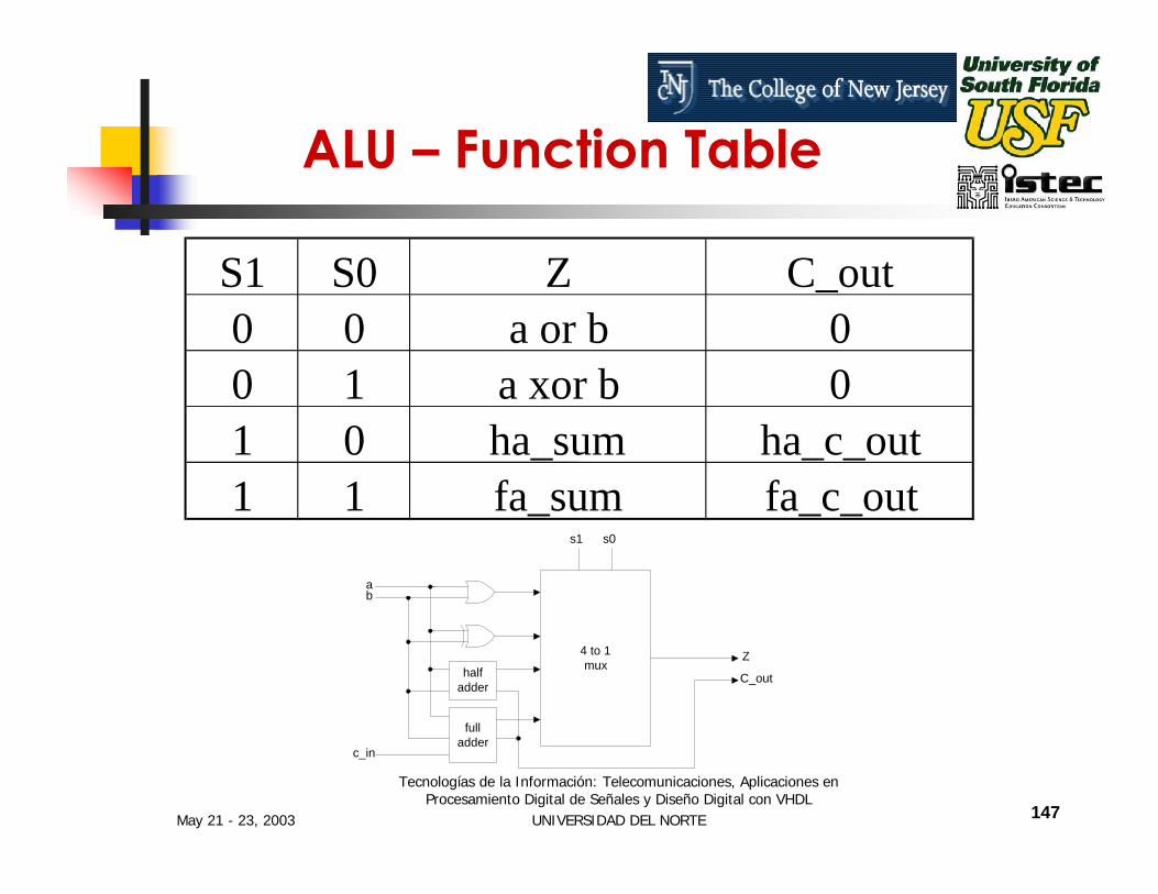
a b
c_in
Z
C_out
s1 s0
4 to 1muxhalf
adder
fulladder
ALU – Function Table
S1 S0 Z C_out0 0 a or b 00 1 a xor b 01 0 ha_sum ha_c_out1 1 fa_sum fa_c_out
May 21 - 23, 2003
Tecnologías de la Información: Telecomunicaciones, Aplicaciones en Procesamiento Digital de Señales y Diseño Digital con VHDL
UNIVERSIDAD DEL NORTE 148
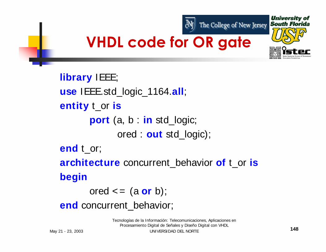
VHDL code for OR gate
library IEEE;use IEEE.std_logic_1164.all;entity t_or is
port (a, b : in std_logic;ored : out std_logic);
end t_or;architecture concurrent_behavior of t_or isbegin
ored <= (a or b);end concurrent_behavior;

May 21 - 23, 2003
Tecnologías de la Información: Telecomunicaciones, Aplicaciones en Procesamiento Digital de Señales y Diseño Digital con VHDL
UNIVERSIDAD DEL NORTE 149
Max+Plus II T_OR, Code Entry
May 21 - 23, 2003
Tecnologías de la Información: Telecomunicaciones, Aplicaciones en Procesamiento Digital de Señales y Diseño Digital con VHDL
UNIVERSIDAD DEL NORTE 150
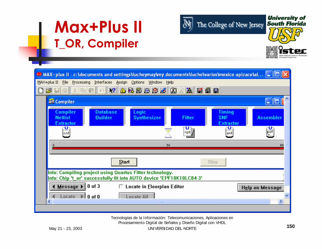
Max+Plus II T_OR, Compiler
May 21 - 23, 2003
Tecnologías de la Información: Telecomunicaciones, Aplicaciones en Procesamiento Digital de Señales y Diseño Digital con VHDL
UNIVERSIDAD DEL NORTE 151
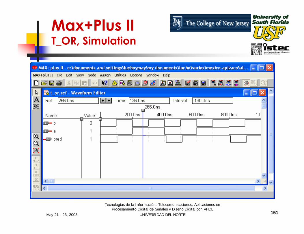
Max+Plus II T_OR, Simulation
May 21 - 23, 2003
Tecnologías de la Información: Telecomunicaciones, Aplicaciones en Procesamiento Digital de Señales y Diseño Digital con VHDL
UNIVERSIDAD DEL NORTE 152
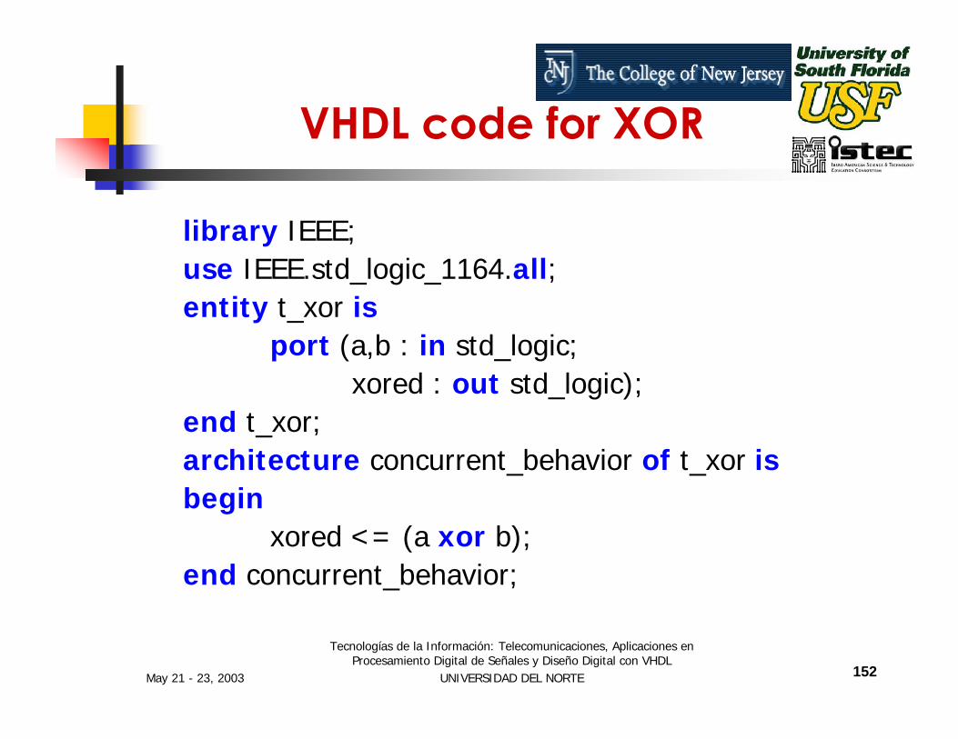
VHDL code for XOR
library IEEE;use IEEE.std_logic_1164.all;entity t_xor is
port (a,b : in std_logic;xored : out std_logic);
end t_xor;architecture concurrent_behavior of t_xor isbegin
xored <= (a xor b);end concurrent_behavior;
May 21 - 23, 2003
Tecnologías de la Información: Telecomunicaciones, Aplicaciones en Procesamiento Digital de Señales y Diseño Digital con VHDL
UNIVERSIDAD DEL NORTE 153
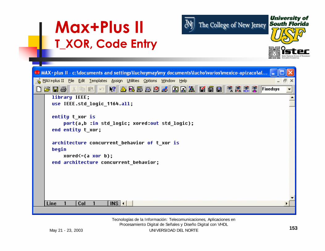
Max+Plus II T_XOR, Code Entry
May 21 - 23, 2003
Tecnologías de la Información: Telecomunicaciones, Aplicaciones en Procesamiento Digital de Señales y Diseño Digital con VHDL
UNIVERSIDAD DEL NORTE 154
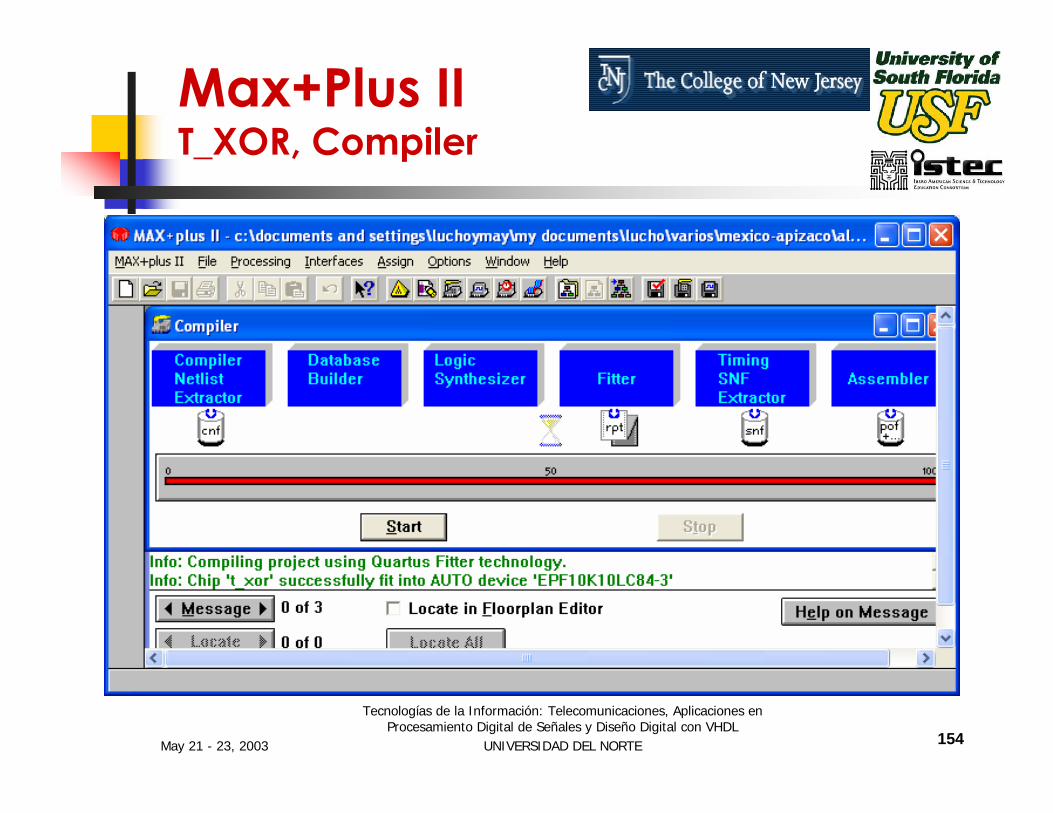
Max+Plus II T_XOR, Compiler

May 21 - 23, 2003
Tecnologías de la Información: Telecomunicaciones, Aplicaciones en Procesamiento Digital de Señales y Diseño Digital con VHDL
UNIVERSIDAD DEL NORTE 155
Max+Plus II T_XOR, Simulation
May 21 - 23, 2003
Tecnologías de la Información: Telecomunicaciones, Aplicaciones en Procesamiento Digital de Señales y Diseño Digital con VHDL
UNIVERSIDAD DEL NORTE 156
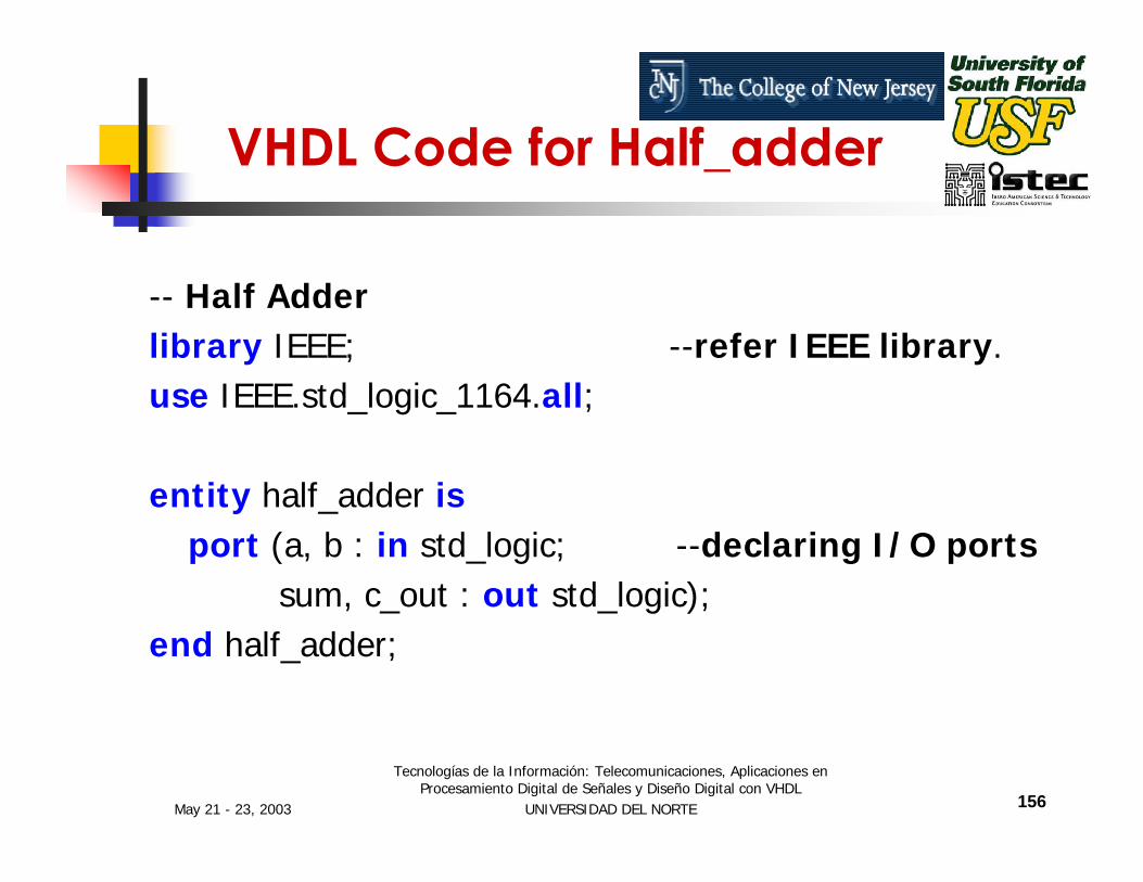
VHDL Code for Half_adder
-- Half Adderlibrary IEEE; --refer IEEE library.use IEEE.std_logic_1164.all;
entity half_adder isport (a, b : in std_logic; --declaring I/O ports
sum, c_out : out std_logic);end half_adder;

May 21 - 23, 2003
Tecnologías de la Información: Telecomunicaciones, Aplicaciones en Procesamiento Digital de Señales y Diseño Digital con VHDL
UNIVERSIDAD DEL NORTE 157
Half_Adder code (cont…)
architecture behavior ofhalf_adder is
beginsum <= (a xor b);c_out <= (a and b);
end behavior;
sum
carry
a
b
Figure 1-1 Half adder circuit

May 21 - 23, 2003
Tecnologías de la Información: Telecomunicaciones, Aplicaciones en Procesamiento Digital de Señales y Diseño Digital con VHDL
UNIVERSIDAD DEL NORTE 158
Max+Plus II Half-Adder, Code Entry

May 21 - 23, 2003
Tecnologías de la Información: Telecomunicaciones, Aplicaciones en Procesamiento Digital de Señales y Diseño Digital con VHDL
UNIVERSIDAD DEL NORTE 159
Max+Plus II Half-Adder, Compiler

May 21 - 23, 2003
Tecnologías de la Información: Telecomunicaciones, Aplicaciones en Procesamiento Digital de Señales y Diseño Digital con VHDL
UNIVERSIDAD DEL NORTE 160
Max+Plus II Half-Adder, Simulation

May 21 - 23, 2003
Tecnologías de la Información: Telecomunicaciones, Aplicaciones en Procesamiento Digital de Señales y Diseño Digital con VHDL
UNIVERSIDAD DEL NORTE 161
Full Adder circuit
ab
c_in
sum
c_out
s1
s3s2

May 21 - 23, 2003
Tecnologías de la Información: Telecomunicaciones, Aplicaciones en Procesamiento Digital de Señales y Diseño Digital con VHDL
UNIVERSIDAD DEL NORTE 162
VHDL code for Full Adder
--Full_Adderlibrary IEEE;use IEEE.std_logic_1164.all;
entity full_adder isport (a, b, c_in : in std_logic;
sum, c_out : out std_logic);end full_adder;
May 21 - 23, 2003
Tecnologías de la Información: Telecomunicaciones, Aplicaciones en Procesamiento Digital de Señales y Diseño Digital con VHDL
UNIVERSIDAD DEL NORTE 163
architecture dataflow of full_adder issignal s1, s2, s3 : std_logic;
beginL1: s1 <= (a xor b);L2: s2 <= (c_in and s1);L3: s3 <= (a and b);L4: sum <= (s1 xor c_in);L5: c_out <= (s2 or s3);
end dataflow;
-- Using Signal Assignment Instructions
VHDL code for Full Adder
May 21 - 23, 2003
Tecnologías de la Información: Telecomunicaciones, Aplicaciones en Procesamiento Digital de Señales y Diseño Digital con VHDL
UNIVERSIDAD DEL NORTE 164
Max+Plus II Full-Adder, Code Entry
May 21 - 23, 2003
Tecnologías de la Información: Telecomunicaciones, Aplicaciones en Procesamiento Digital de Señales y Diseño Digital con VHDL
UNIVERSIDAD DEL NORTE 165
Max+Plus II Full-Adder, Compiler

May 21 - 23, 2003
Tecnologías de la Información: Telecomunicaciones, Aplicaciones en Procesamiento Digital de Señales y Diseño Digital con VHDL
UNIVERSIDAD DEL NORTE 166
Max+Plus II Full-Adder, Simulation
May 21 - 23, 2003
Tecnologías de la Información: Telecomunicaciones, Aplicaciones en Procesamiento Digital de Señales y Diseño Digital con VHDL
UNIVERSIDAD DEL NORTE 167
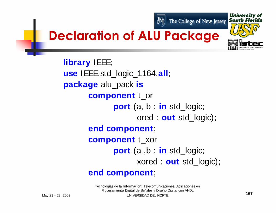
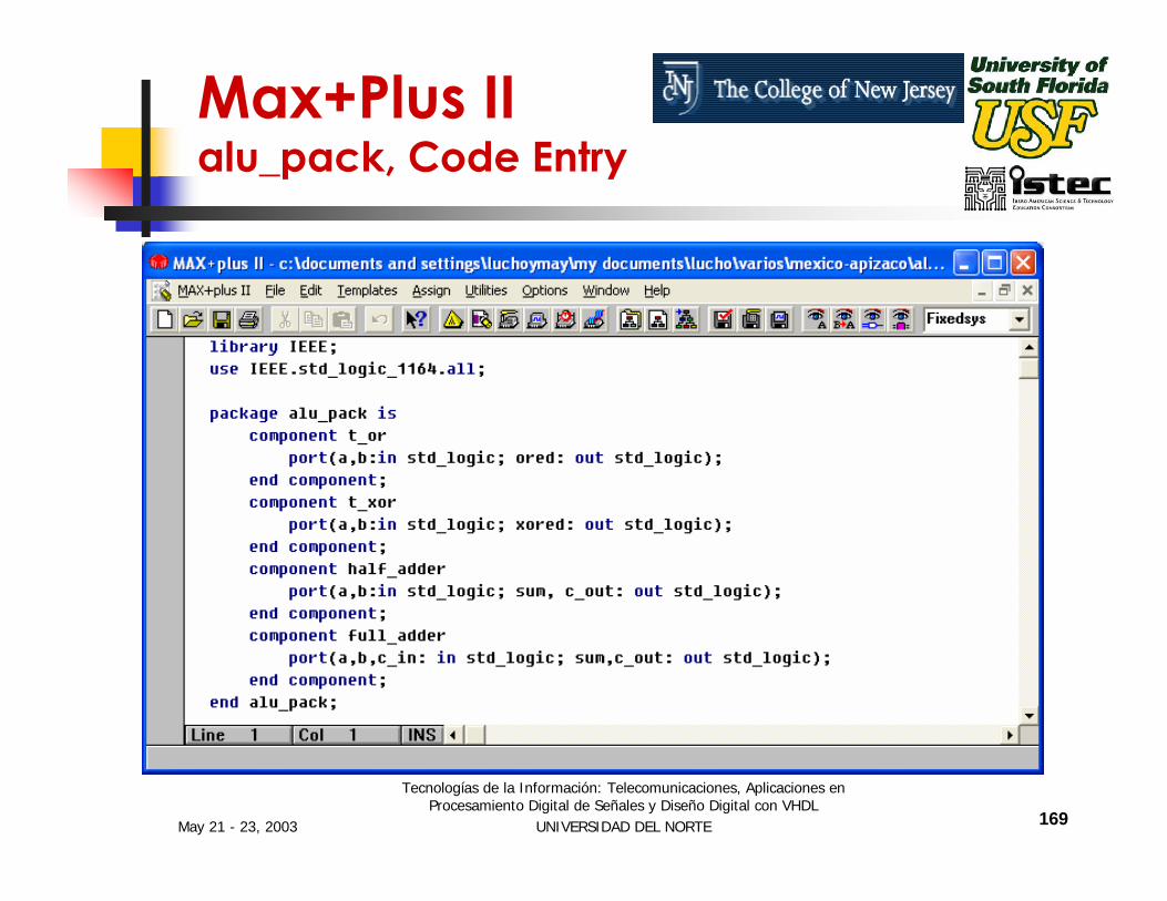
library IEEE;use IEEE.std_logic_1164.all;package alu_pack is
component t_orport (a, b : in std_logic;
ored : out std_logic);end component;component t_xor
port (a ,b : in std_logic;xored : out std_logic);
end component;
Declaration of ALU Package

May 21 - 23, 2003
Tecnologías de la Información: Telecomunicaciones, Aplicaciones en Procesamiento Digital de Señales y Diseño Digital con VHDL
UNIVERSIDAD DEL NORTE 168
component half_adderport (a, b : in std_logic;
ha_sum, c_out : out std_logic);end component;component full_adder
port (a, b, c_in : in std_logic;sum, c_out : out std_logic);
end component;
end alu_pack;
Declaration of ALU Package
May 21 - 23, 2003
Tecnologías de la Información: Telecomunicaciones, Aplicaciones en Procesamiento Digital de Señales y Diseño Digital con VHDL
UNIVERSIDAD DEL NORTE 169
Max+Plus II alu_pack, Code Entry

May 21 - 23, 2003
Tecnologías de la Información: Telecomunicaciones, Aplicaciones en Procesamiento Digital de Señales y Diseño Digital con VHDL
UNIVERSIDAD DEL NORTE 170
Max+Plus II alu_pack, Compiler
May 21 - 23, 2003
Tecnologías de la Información: Telecomunicaciones, Aplicaciones en Procesamiento Digital de Señales y Diseño Digital con VHDL
UNIVERSIDAD DEL NORTE 171
Max+Plus II alu_pack, Simulation
The ALU_PACK design can not be simulated since it is a Package.
Its operation will be verified together with the designs that will use it. In this case this will be the ALU main design.

May 21 - 23, 2003
Tecnologías de la Información: Telecomunicaciones, Aplicaciones en Procesamiento Digital de Señales y Diseño Digital con VHDL
UNIVERSIDAD DEL NORTE 172
Main Code for ALU
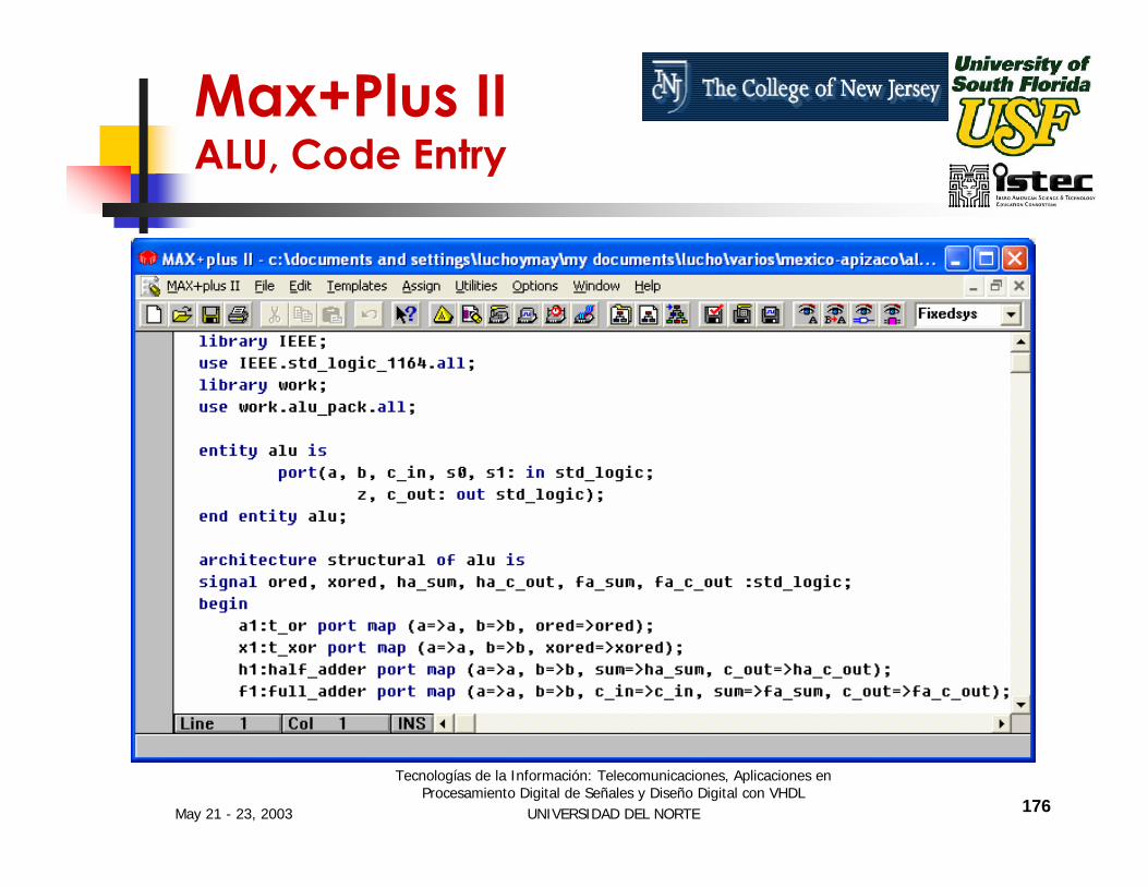
library IEEE;use IEEE.std_logic_1164.all;library work;use work.alu_pack.all;
entity alu isport (a, b, c_in, s0, s1 : in std_logic;
z, c_out : out std_logic);end alu;

May 21 - 23, 2003
Tecnologías de la Información: Telecomunicaciones, Aplicaciones en Procesamiento Digital de Señales y Diseño Digital con VHDL
UNIVERSIDAD DEL NORTE 173
architecture structural of alu is
signal ored, xored, ha_sum, ha_c_out, fa_sum, fa_c_out : std_logic;
begina1: t_or port map (a => a, b => b, ored => ored);x1: t_xor port map (a => a, b => b, xored => xored);h1: half_adder port map (a => a, b => b,
sum => ha_sum, c_out => ha_c_out);f1: full_adder port map (a => a, b => b,
c_in => c_in, sum => fa_sum,c_out => fa_c_out);
Main Code for ALU Cont…

May 21 - 23, 2003
Tecnologías de la Información: Telecomunicaciones, Aplicaciones en Procesamiento Digital de Señales y Diseño Digital con VHDL
UNIVERSIDAD DEL NORTE 174
alu_process: process (a, b, c_in, s0, s1)begin
if (s1 = '0' and s0 = '0') thenz <= ored;c_out <= '0';
end if;if (s1 = '0' and s0 = '1') then
z <= xored;c_out <= '0';
end if;
Main Code for ALU Cont….
May 21 - 23, 2003
Tecnologías de la Información: Telecomunicaciones, Aplicaciones en Procesamiento Digital de Señales y Diseño Digital con VHDL
UNIVERSIDAD DEL NORTE 175
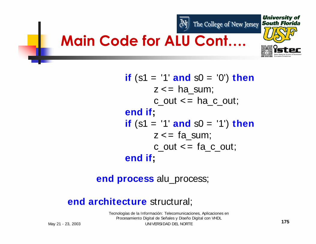
if (s1 = '1' and s0 = '0') thenz <= ha_sum;c_out <= ha_c_out;
end if;if (s1 = '1' and s0 = '1') then
z <= fa_sum;c_out <= fa_c_out;
end if;
end process alu_process;
end architecture structural;
Main Code for ALU Cont….
May 21 - 23, 2003
Tecnologías de la Información: Telecomunicaciones, Aplicaciones en Procesamiento Digital de Señales y Diseño Digital con VHDL
UNIVERSIDAD DEL NORTE 176
Max+Plus II ALU, Code Entry

May 21 - 23, 2003
Tecnologías de la Información: Telecomunicaciones, Aplicaciones en Procesamiento Digital de Señales y Diseño Digital con VHDL
UNIVERSIDAD DEL NORTE 177
Max+Plus II ALU, Compiler
May 21 - 23, 2003
Tecnologías de la Información: Telecomunicaciones, Aplicaciones en Procesamiento Digital de Señales y Diseño Digital con VHDL
UNIVERSIDAD DEL NORTE 178
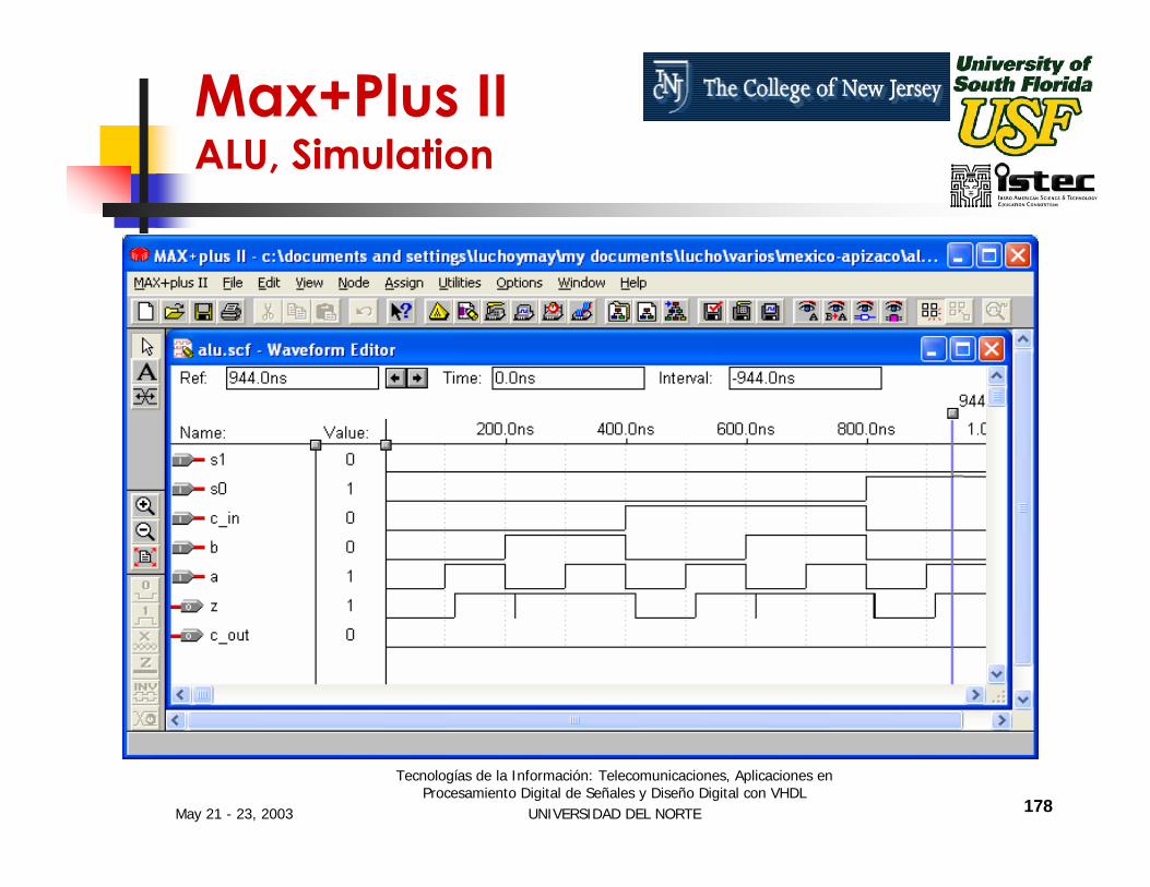
Max+Plus II ALU, Simulation

May 21 - 23, 2003
Tecnologías de la Información: Telecomunicaciones, Aplicaciones en Procesamiento Digital de Señales y Diseño Digital con VHDL
UNIVERSIDAD DEL NORTE 179
Session III
CONTROL AND DATA PATH ORGANIZATION
May 21 - 23, 2003
Tecnologías de la Información: Telecomunicaciones, Aplicaciones en Procesamiento Digital de Señales y Diseño Digital con VHDL
UNIVERSIDAD DEL NORTE 180
Control and Data Path Organization
Most complex digital circuits can be broken up into two parts:
ControlData Path

May 21 - 23, 2003
Tecnologías de la Información: Telecomunicaciones, Aplicaciones en Procesamiento Digital de Señales y Diseño Digital con VHDL
UNIVERSIDAD DEL NORTE 181
Control and Data Path Organization
CONTROLPROCESSING
BLOCK
DATAPROCESSING
BLOCK
DATACONTROLINPUTS
STATUS
CONTROL
OBSERVATION

May 21 - 23, 2003
Tecnologías de la Información: Telecomunicaciones, Aplicaciones en Procesamiento Digital de Señales y Diseño Digital con VHDL
UNIVERSIDAD DEL NORTE 182
Finite State Machines
Two Classes of Finite State Machines (FSMs):
Moore MachinesMealy Machines

May 21 - 23, 2003
Tecnologías de la Información: Telecomunicaciones, Aplicaciones en Procesamiento Digital de Señales y Diseño Digital con VHDL
UNIVERSIDAD DEL NORTE 183
Outputs depend only on the stateState and Outputs Processing are combinational elementsState Vector is Sequential Elements
Moore Finite State Machines
STATEVECTOR
OUTPUTSPROCESSING
NEXT STATEPROCESSING
CLOCK
OUTPUTSINPUTS
May 21 - 23, 2003
Tecnologías de la Información: Telecomunicaciones, Aplicaciones en Procesamiento Digital de Señales y Diseño Digital con VHDL
UNIVERSIDAD DEL NORTE 184
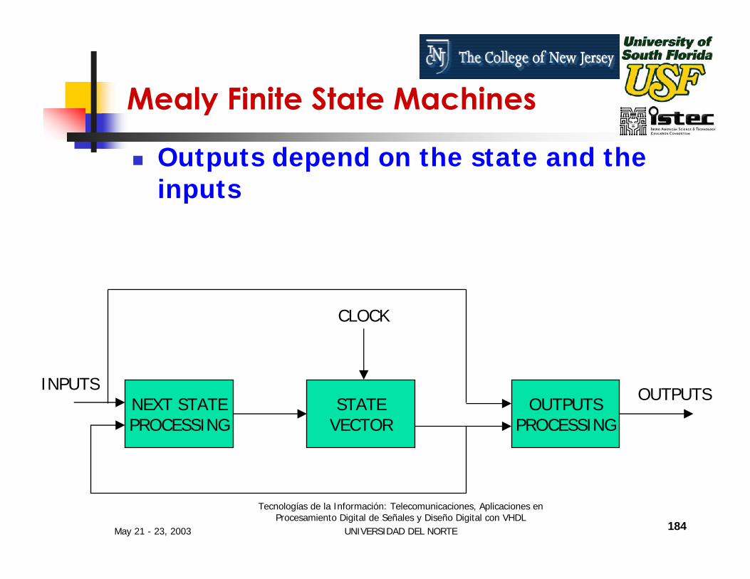
Outputs depend on the state and the inputs
Mealy Finite State Machines
STATEVECTOR
OUTPUTSPROCESSING
NEXT STATEPROCESSING
CLOCK
OUTPUTSINPUTS

May 21 - 23, 2003
Tecnologías de la Información: Telecomunicaciones, Aplicaciones en Procesamiento Digital de Señales y Diseño Digital con VHDL
UNIVERSIDAD DEL NORTE 185
Session IV
VHDL IMPLEMENTATION EXAMPLES – A Decimation Filter for a Sigma-Delta Analog to Digital Converter
May 21 - 23, 2003
Tecnologías de la Información: Telecomunicaciones, Aplicaciones en Procesamiento Digital de Señales y Diseño Digital con VHDL
UNIVERSIDAD DEL NORTE 186
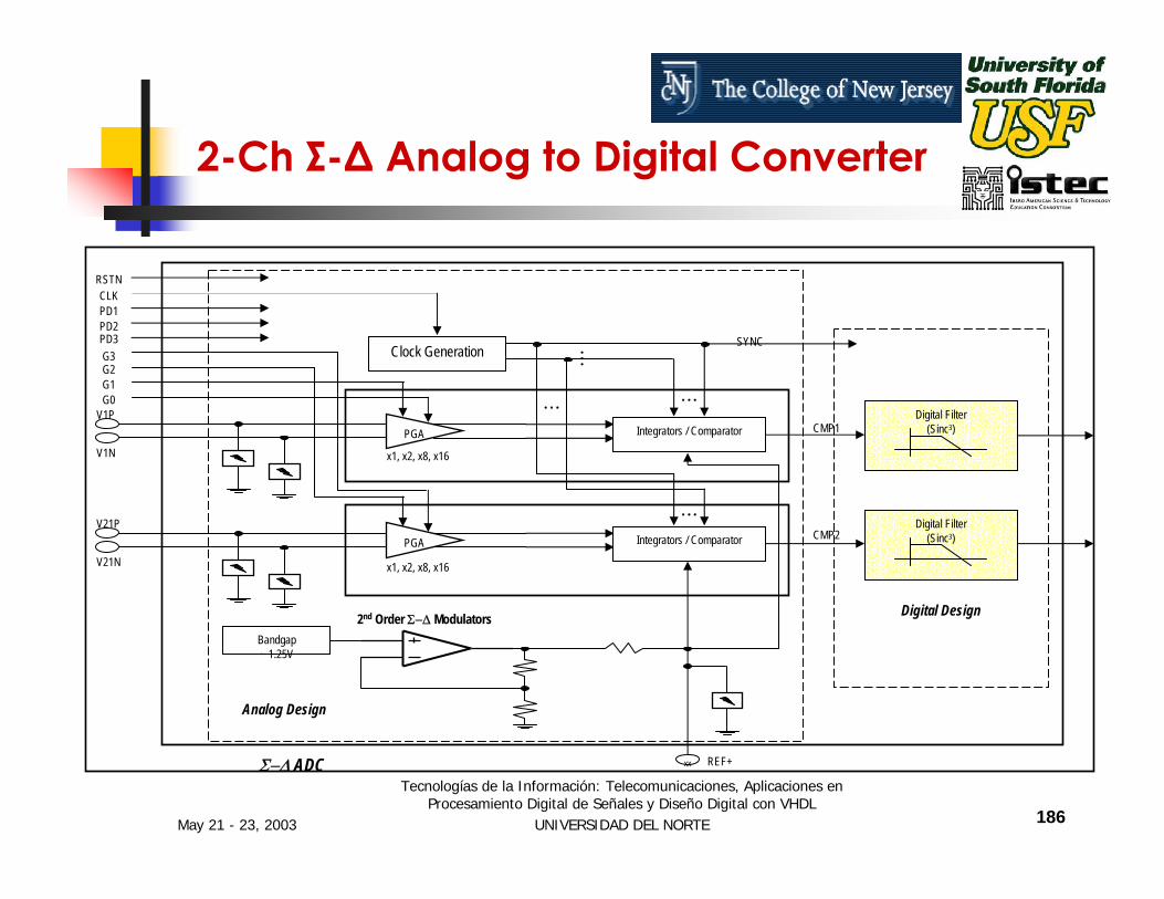
2-Ch Σ-∆ Analog to Digital Converter
Bandgap~ 1.25V
Digital Filter(Sinc3)
Digital Design
V1P
V1N
xx REF+
V21P
V21N
Clock GenerationG3
x1, x2, x8, x16
PGA Integrators / Comparator
PGA Integrators / Comparator
x1, x2, x8, x16
M
L
L
L Digital Filter(Sinc3)
Analog Design
Σ−∆ ADC
SYNC
G2G1G0
CLKPD1PD2PD3
2nd Order Σ−∆ Modulators
RSTN
CMP1
CMP2

May 21 - 23, 2003
Tecnologías de la Información: Telecomunicaciones, Aplicaciones en Procesamiento Digital de Señales y Diseño Digital con VHDL
UNIVERSIDAD DEL NORTE 187
2nd Order Σ-∆ Modulator (block/algorithmic)
z-1
z-1
IN
OUT
CREF
1 / CFA CX / CFBCIN
CY / CFB
This can be modeled in Behavioral VHDL
May 21 - 23, 2003
Tecnologías de la Información: Telecomunicaciones, Aplicaciones en Procesamiento Digital de Señales y Diseño Digital con VHDL
UNIVERSIDAD DEL NORTE 188
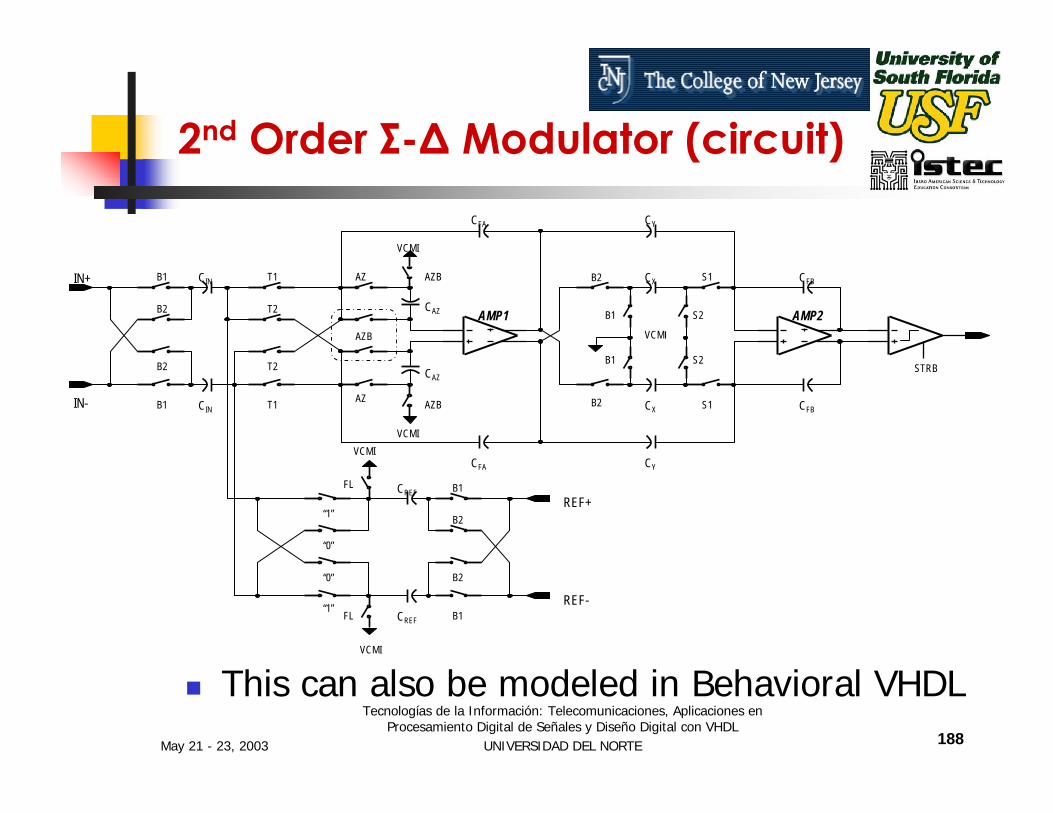
2nd Order Σ-∆ Modulator (circuit)
This can also be modeled in Behavioral VHDL
VCMI
VCMI
VCMI
CAZ
CAZ
CFA
CFA
VCMI
VCMI
CIN
CIN
CY
CX
CX
CY
CFB
CFB
CREF
CREF
AZB
AZB
AZB
AZ
AZ
T1
T2
T2
T1
B1
B2
B2
B1
B1
B2
B2
B1
B2 S1
B2
B1 S2
B1 S2
S1
STRB
REF+
REF-
IN+
IN-
FL
FL
“1”
“0”
“0”
“1”
AMP1 AMP2

May 21 - 23, 2003
Tecnologías de la Información: Telecomunicaciones, Aplicaciones en Procesamiento Digital de Señales y Diseño Digital con VHDL
UNIVERSIDAD DEL NORTE 189
Decimation Digital Filter
z-1 z-1 z-1
z-1 z-1 z-1
fs
fs / OSR
IN
OUT
fs / OSR

May 21 - 23, 2003
Tecnologías de la Información: Telecomunicaciones, Aplicaciones en Procesamiento Digital de Señales y Diseño Digital con VHDL
UNIVERSIDAD DEL NORTE 190
Decimation Digital Filter
Cubic sincBits of noise free accuracy for delta-sigma ADC's:
BITS = 3 * LOG(OSR) / LOG(2) + 2Assume OSR=32, then BITS=17, and set BITS=16
May 21 - 23, 2003
Tecnologías de la Información: Telecomunicaciones, Aplicaciones en Procesamiento Digital de Señales y Diseño Digital con VHDL
UNIVERSIDAD DEL NORTE 191
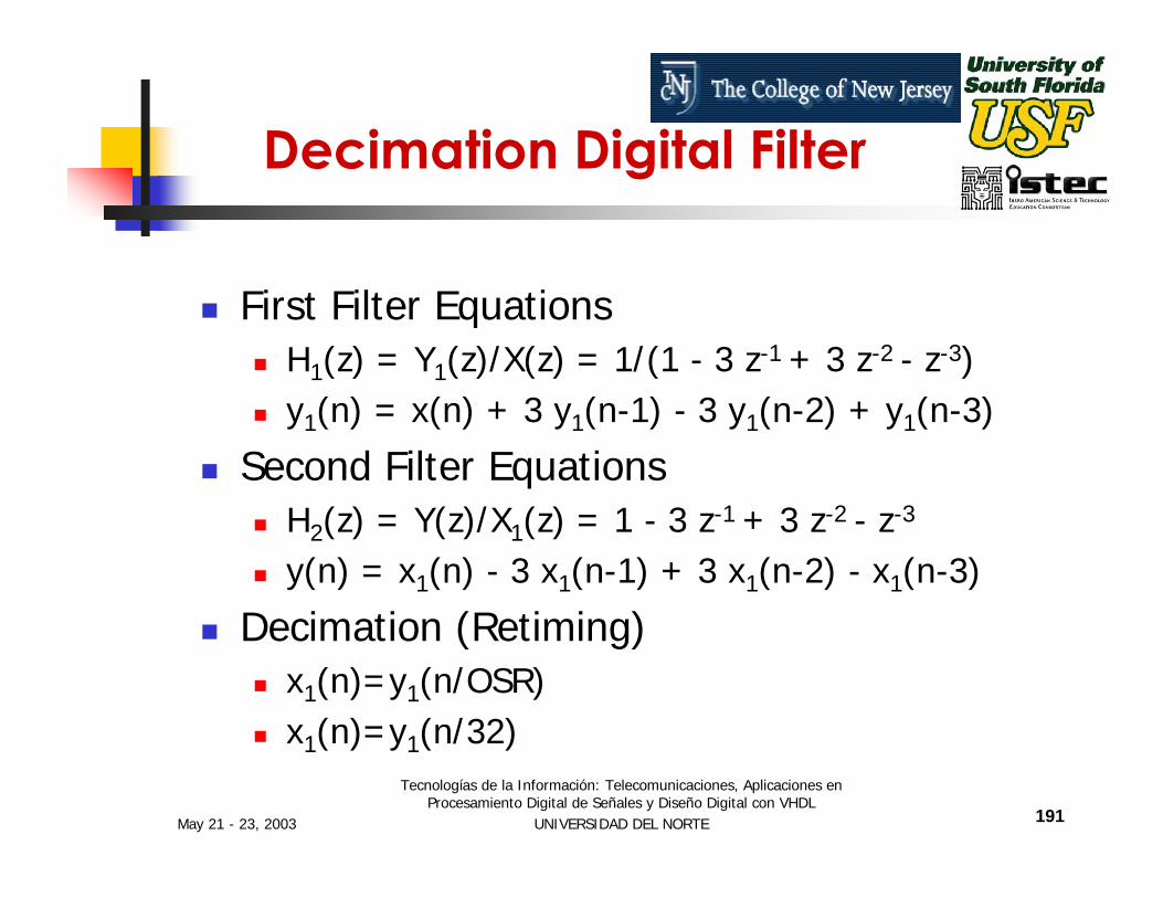
Decimation Digital Filter
First Filter EquationsH1(z) = Y1(z)/X(z) = 1/(1 - 3 z-1 + 3 z-2 - z-3)y1(n) = x(n) + 3 y1(n-1) - 3 y1(n-2) + y1(n-3)
Second Filter EquationsH2(z) = Y(z)/X1(z) = 1 - 3 z-1 + 3 z-2 - z-3
y(n) = x1(n) - 3 x1(n-1) + 3 x1(n-2) - x1(n-3)
Decimation (Retiming)x1(n)=y1(n/OSR)x1(n)=y1(n/32)

May 21 - 23, 2003
Tecnologías de la Información: Telecomunicaciones, Aplicaciones en Procesamiento Digital de Señales y Diseño Digital con VHDL
UNIVERSIDAD DEL NORTE 192
What do we need for our design?y1(n) = x(n) + 3 y1(n-1) - 3 y1(n-2) + y1(n-3)y(n) = x1(n) - 3 x1(n-1) + 3 x1(n-2) - x1(n-3)x1(n)=y1(n/32)
ControlOn every x(n)
S02: Store x(n) in accumulator, count x(n) mod 32S03: Accumulate 2 y1(n-1)S04: Accumulate y1(n-1)S05: Accumulate 1’s complement of 2 y1(n-2)S06: Accumulate 1’s complement of y1(n-2)S07: Accumulate 2S08: Accumulate y1(n-3)S09: Update y registers
On every x1(n) (every 32nd y1(n))S10: Accumulate 1’s complement of 2 x1(n-1)S11: Accumulate 1’s complement of x1(n-1)S12: Accumulate 2 x1(n-2)S13: Accumulate x1(n-2)S14: Accumulate 1’s complement of x1(n-3)S15: Accumulate 3, output resultS16: Store y1(n-1) in accumulatorS17: Update x registers
Data Path16 bitsAdder-Accumulator1’s complementShift left by one (x 2)Store y1(n-1), y1(n-2), y1(n-3)Store x1(n-1), x1(n-2), x1(n-3)Constants: 2 & 3
May 21 - 23, 2003
Tecnologías de la Información: Telecomunicaciones, Aplicaciones en Procesamiento Digital de Señales y Diseño Digital con VHDL
UNIVERSIDAD DEL NORTE 193
OUT
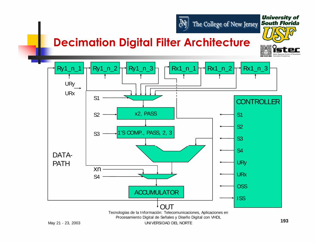
Decimation Digital Filter Architecture
Ry1_n_1 Ry1_n_2 Ry1_n_3 Rx1_n_1 Rx1_n_2 Rx1_n_3
ACCUMULATOR
x2, PASS
1’S COMP., PASS, 2, 3
xn
URy
S1
S2
S3
S4
CONTROLLER
S1
S2
S3
S4
URy
URx
OSS
DATA-PATH
URx
ISS
May 21 - 23, 2003
Tecnologías de la Información: Telecomunicaciones, Aplicaciones en Procesamiento Digital de Señales y Diseño Digital con VHDL
UNIVERSIDAD DEL NORTE 194
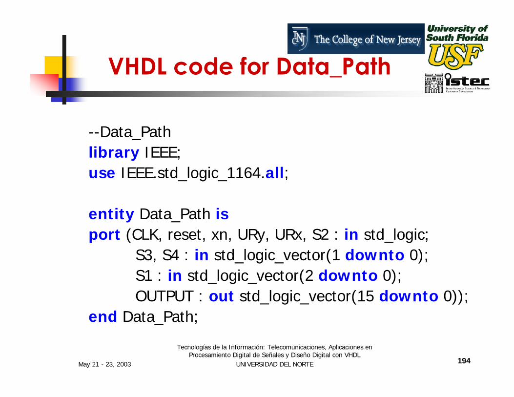
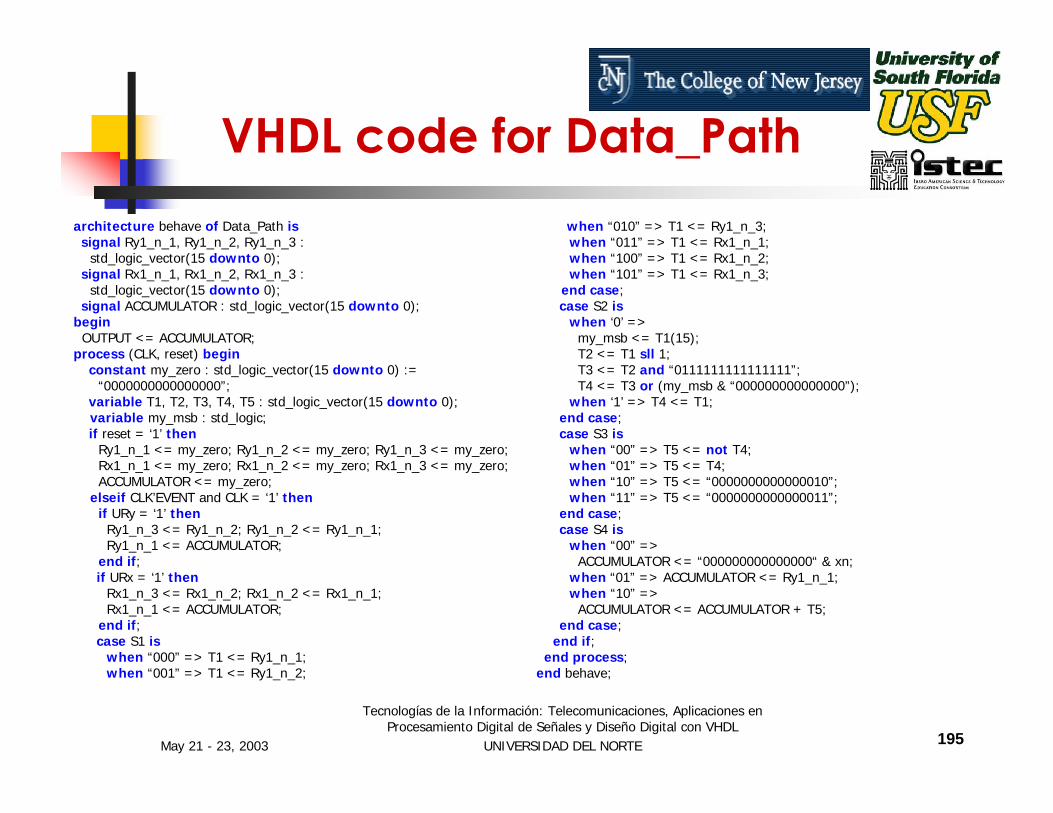
VHDL code for Data_Path
--Data_Pathlibrary IEEE;use IEEE.std_logic_1164.all;
entity Data_Path isport (CLK, reset, xn, URy, URx, S2 : in std_logic;
S3, S4 : in std_logic_vector(1 downto 0);S1 : in std_logic_vector(2 downto 0);OUTPUT : out std_logic_vector(15 downto 0));
end Data_Path;
May 21 - 23, 2003
Tecnologías de la Información: Telecomunicaciones, Aplicaciones en Procesamiento Digital de Señales y Diseño Digital con VHDL
UNIVERSIDAD DEL NORTE 195
architecture behave of Data_Path issignal Ry1_n_1, Ry1_n_2, Ry1_n_3 :
std_logic_vector(15 downto 0);signal Rx1_n_1, Rx1_n_2, Rx1_n_3 :
std_logic_vector(15 downto 0);signal ACCUMULATOR : std_logic_vector(15 downto 0);
beginOUTPUT <= ACCUMULATOR;
process (CLK, reset) beginconstant my_zero : std_logic_vector(15 downto 0) :=
“0000000000000000”;variable T1, T2, T3, T4, T5 : std_logic_vector(15 downto 0);variable my_msb : std_logic;if reset = ‘1’ then
Ry1_n_1 <= my_zero; Ry1_n_2 <= my_zero; Ry1_n_3 <= my_zero;Rx1_n_1 <= my_zero; Rx1_n_2 <= my_zero; Rx1_n_3 <= my_zero;ACCUMULATOR <= my_zero;
elseif CLK’EVENT and CLK = ‘1’ thenif URy = ‘1’ thenRy1_n_3 <= Ry1_n_2; Ry1_n_2 <= Ry1_n_1;Ry1_n_1 <= ACCUMULATOR;
end if;if URx = ‘1’ then
Rx1_n_3 <= Rx1_n_2; Rx1_n_2 <= Rx1_n_1;Rx1_n_1 <= ACCUMULATOR;
end if;case S1 is
when “000” => T1 <= Ry1_n_1;when “001” => T1 <= Ry1_n_2;
VHDL code for Data_Pathwhen “010” => T1 <= Ry1_n_3;when “011” => T1 <= Rx1_n_1;when “100” => T1 <= Rx1_n_2;when “101” => T1 <= Rx1_n_3;
end case;case S2 is
when ‘0’ =>my_msb <= T1(15);T2 <= T1 sll 1;T3 <= T2 and “0111111111111111”;T4 <= T3 or (my_msb & “000000000000000”);
when ‘1’ => T4 <= T1;end case;case S3 is
when “00” => T5 <= not T4;when “01” => T5 <= T4;when “10” => T5 <= “0000000000000010”;when “11” => T5 <= “0000000000000011”;
end case;case S4 is
when “00” =>ACCUMULATOR <= “000000000000000“ & xn;
when “01” => ACCUMULATOR <= Ry1_n_1;when “10” =>ACCUMULATOR <= ACCUMULATOR + T5;
end case;end if;
end process;end behave;

May 21 - 23, 2003
Tecnologías de la Información: Telecomunicaciones, Aplicaciones en Procesamiento Digital de Señales y Diseño Digital con VHDL
UNIVERSIDAD DEL NORTE 196
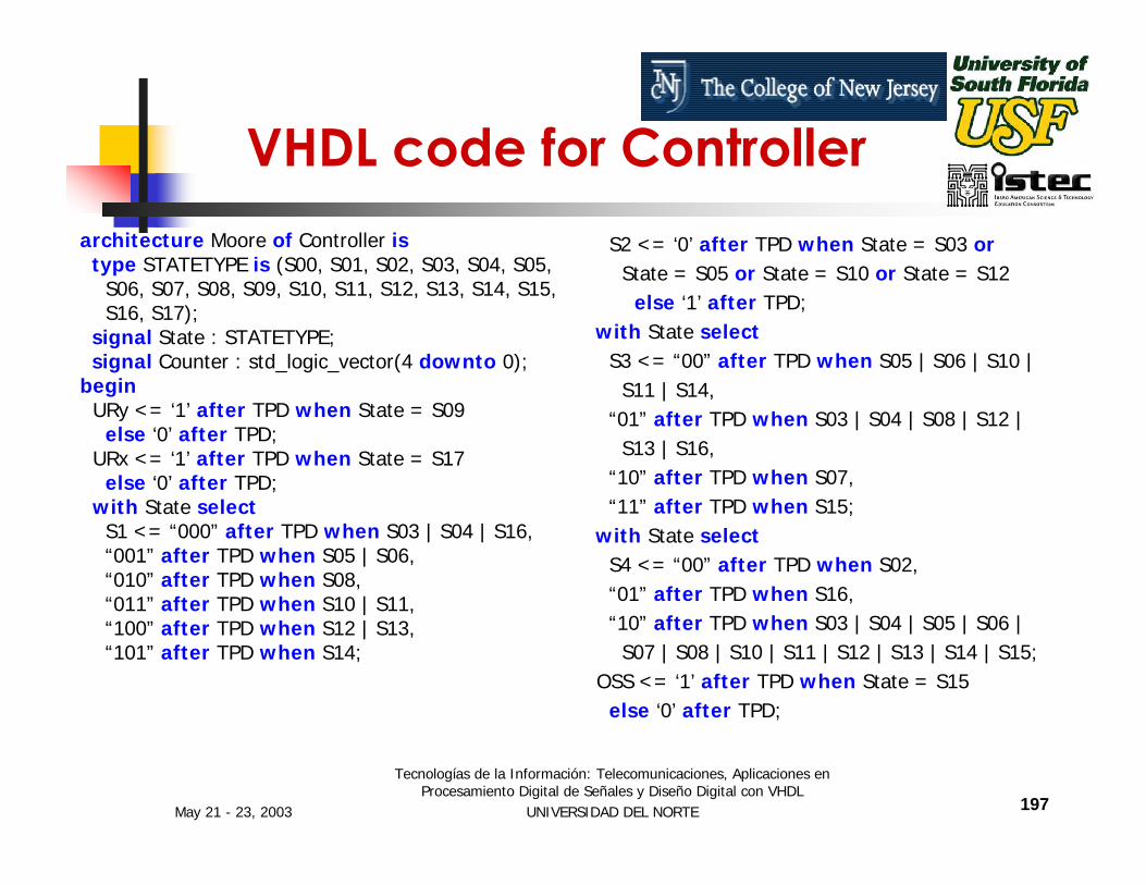
VHDL code for Controller
--Controllerlibrary IEEE;use IEEE.std_logic_1164.all;
entity Controller isgeneric (TPD : TIME := 1 nS);port (CLK, reset, ISS : in std_logic;
URy, URx, S2, OSS : out std_logic;S3, S4 : out std_logic_vector(1 downto 0);S1 : out std_logic_vector(2 downto 0));
end Controller;
May 21 - 23, 2003
Tecnologías de la Información: Telecomunicaciones, Aplicaciones en Procesamiento Digital de Señales y Diseño Digital con VHDL
UNIVERSIDAD DEL NORTE 197
architecture Moore of Controller istype STATETYPE is (S00, S01, S02, S03, S04, S05,
S06, S07, S08, S09, S10, S11, S12, S13, S14, S15,S16, S17);
signal State : STATETYPE;signal Counter : std_logic_vector(4 downto 0);
beginURy <= ‘1’ after TPD when State = S09
else ‘0’ after TPD;URx <= ‘1’ after TPD when State = S17
else ‘0’ after TPD;with State select
S1 <= “000” after TPD when S03 | S04 | S16,“001” after TPD when S05 | S06,“010” after TPD when S08,“011” after TPD when S10 | S11,“100” after TPD when S12 | S13,“101” after TPD when S14;
VHDL code for ControllerS2 <= ‘0’ after TPD when State = S03 or
State = S05 or State = S10 or State = S12else ‘1’ after TPD;
with State selectS3 <= “00” after TPD when S05 | S06 | S10 |
S11 | S14,“01” after TPD when S03 | S04 | S08 | S12 |
S13 | S16,“10” after TPD when S07,“11” after TPD when S15;
with State selectS4 <= “00” after TPD when S02,“01” after TPD when S16,“10” after TPD when S03 | S04 | S05 | S06 |
S07 | S08 | S10 | S11 | S12 | S13 | S14 | S15;OSS <= ‘1’ after TPD when State = S15
else ‘0’ after TPD;

May 21 - 23, 2003
Tecnologías de la Información: Telecomunicaciones, Aplicaciones en Procesamiento Digital de Señales y Diseño Digital con VHDL
UNIVERSIDAD DEL NORTE 198
process (CLK, reset) beginif reset = ‘1’ then State <= S00;elseif CLK’EVENT and CLK = ‘1’ then
case State iswhen S00 =>
if ISS = ‘1’ then State <= S02;end if;
when S01 =>if ISS = ‘1’ then State <= S02;end if;
when S02 =>if Counter = “11111" then
Counter <= “00000”;else
Counter <= Counter + “00001”;end if;State <= S03;
when S03 => State <= S04;when S04 => State <= S05;when S05 => State <= S06;when S06 => State <= S07;
VHDL code for Controllerwhen S07 => State <= S08;when S08 => State <= S09;when S09 =>if Counter = “00000” thenState <= S10;
elseState <= S01;
end if;when S10 => State <= S11;when S11 => State <= S12;when S12 => State <= S13;when S13 => State <= S14;when S14 => State <= S15;when S15 => State <= S16;when S16 => State <= S17when S17 => State <= S01;
end case;end if;
end process;end Moore;
May 21 - 23, 2003
Tecnologías de la Información: Telecomunicaciones, Aplicaciones en Procesamiento Digital de Señales y Diseño Digital con VHDL
UNIVERSIDAD DEL NORTE 199
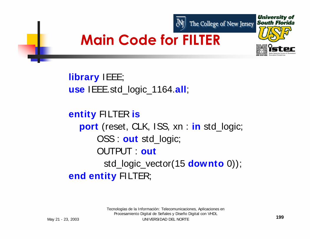
Main Code for FILTER
library IEEE;use IEEE.std_logic_1164.all;
entity FILTER isport (reset, CLK, ISS, xn : in std_logic;
OSS : out std_logic;OUTPUT : out
std_logic_vector(15 downto 0));end entity FILTER;
May 21 - 23, 2003
Tecnologías de la Información: Telecomunicaciones, Aplicaciones en Procesamiento Digital de Señales y Diseño Digital con VHDL
UNIVERSIDAD DEL NORTE 200
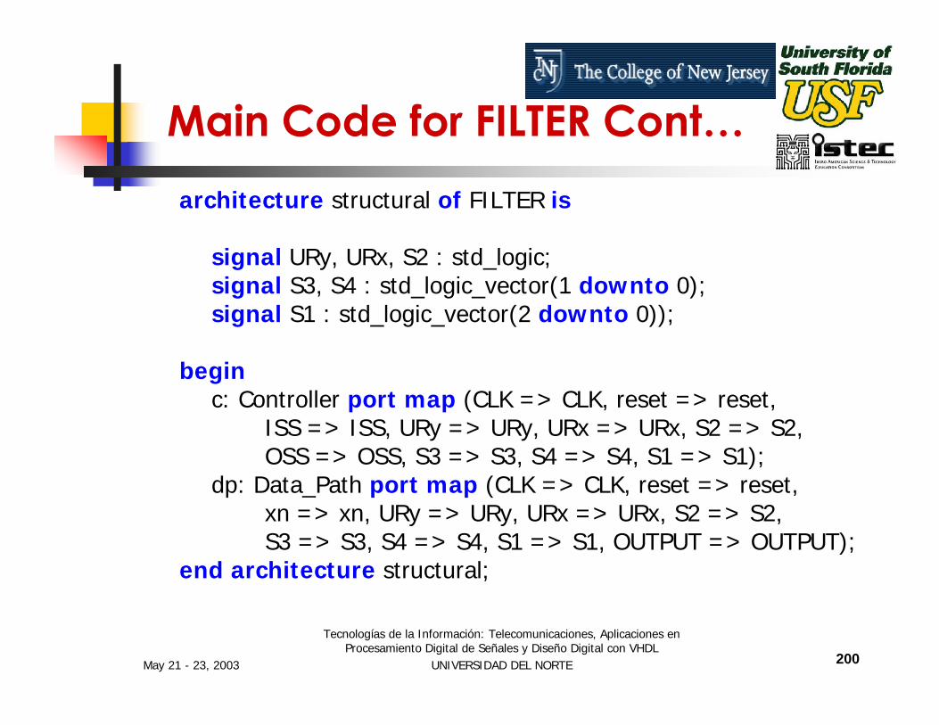
architecture structural of FILTER is
signal URy, URx, S2 : std_logic;signal S3, S4 : std_logic_vector(1 downto 0);signal S1 : std_logic_vector(2 downto 0));
beginc: Controller port map (CLK => CLK, reset => reset,
ISS => ISS, URy => URy, URx => URx, S2 => S2,OSS => OSS, S3 => S3, S4 => S4, S1 => S1);
dp: Data_Path port map (CLK => CLK, reset => reset,xn => xn, URy => URy, URx => URx, S2 => S2,S3 => S3, S4 => S4, S1 => S1, OUTPUT => OUTPUT);
end architecture structural;
Main Code for FILTER Cont…

May 21 - 23, 2003
Tecnologías de la Información: Telecomunicaciones, Aplicaciones en Procesamiento Digital de Señales y Diseño Digital con VHDL
UNIVERSIDAD DEL NORTE 201
Conclusions

May 21 - 23, 2003
Tecnologías de la Información: Telecomunicaciones, Aplicaciones en Procesamiento Digital de Señales y Diseño Digital con VHDL
UNIVERSIDAD DEL NORTE 202
Conclusions
May 21 - 23, 2003
Tecnologías de la Información: Telecomunicaciones, Aplicaciones en Procesamiento Digital de Señales y Diseño Digital con VHDL
UNIVERSIDAD DEL NORTE 203
Implementations and Examples on the
ALTERA UP1 Board

May 21 - 23, 2003
Tecnologías de la Información: Telecomunicaciones, Aplicaciones en Procesamiento Digital de Señales y Diseño Digital con VHDL
UNIVERSIDAD DEL NORTE 204
[email protected] [email protected]
Thanks……
Top Related