


Languages
Pages
Legal

Radio Phased Arrays for the
Detection of Ultra-High Energy
Neutrinos
Eric Oberla
15-June 2018

2
Phased array: synthesize higher gain
antennas• Deep in-ice antennas limited physical size by borehole dimensions,
typically dipole or bicone type low-gain antennas• Askaryan emission highly beamed Do interferometry at trigger level, push threshold down
Aeff=λ2 𝐺
4π
Antenna effective aperture:
Linear phased array gain (λ/2 element spacing):
GdBi= 10 log10(𝑁 𝐺𝑒𝑙𝑒𝑚𝑒𝑛𝑡)
For example, a linear phased array of 8 dipole antennas (G=1.64) has an array gain of 11 dBi, similar to a typical LPDA or ANITA horn antenna
200-700MHz time-domain simulation, 0-delay beam
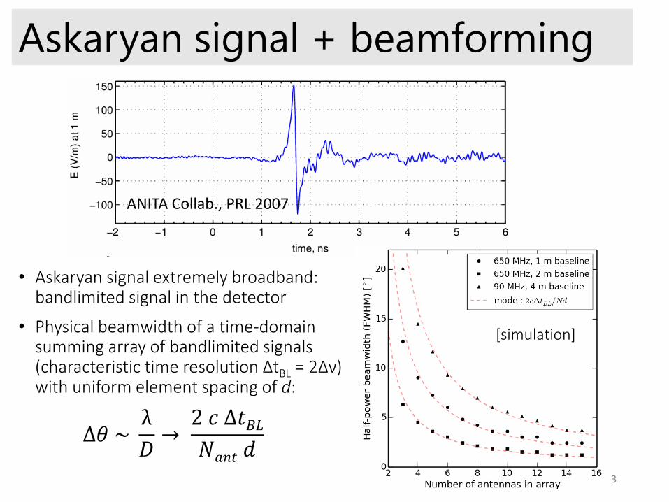
• Askaryan signal extremely broadband: bandlimited signal in the detector
• Physical beamwidth of a time-domain summing array of bandlimited signals (characteristic time resolution ΔtBL = 2Δν) with uniform element spacing of d:
ANITA Collab., PRL 2007
Askaryan signal + beamforming
3
∆𝜃 ~λ
𝐷→
2 𝑐 ∆𝑡𝐵𝐿𝑁𝑎𝑛𝑡 𝑑
[simulation]
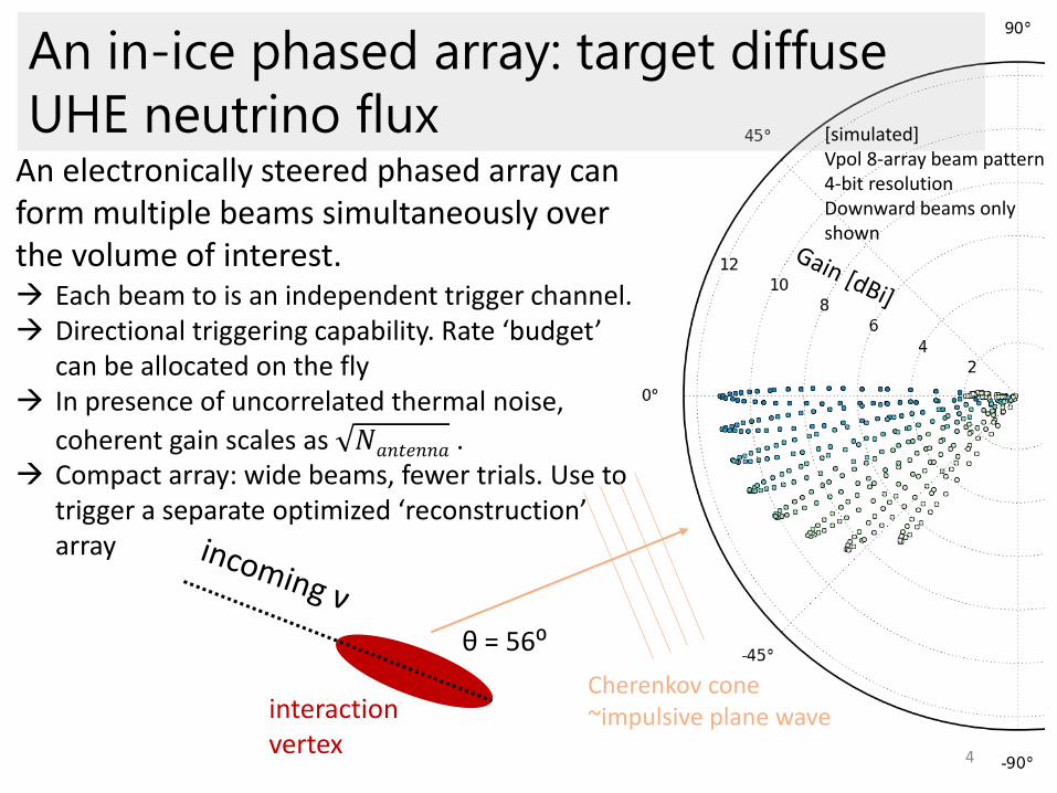
An in-ice phased array: target diffuse
UHE neutrino flux
4
An electronically steered phased array can form multiple beams simultaneously over the volume of interest. Each beam to is an independent trigger channel. Directional triggering capability. Rate ‘budget’
can be allocated on the fly In presence of uncorrelated thermal noise,
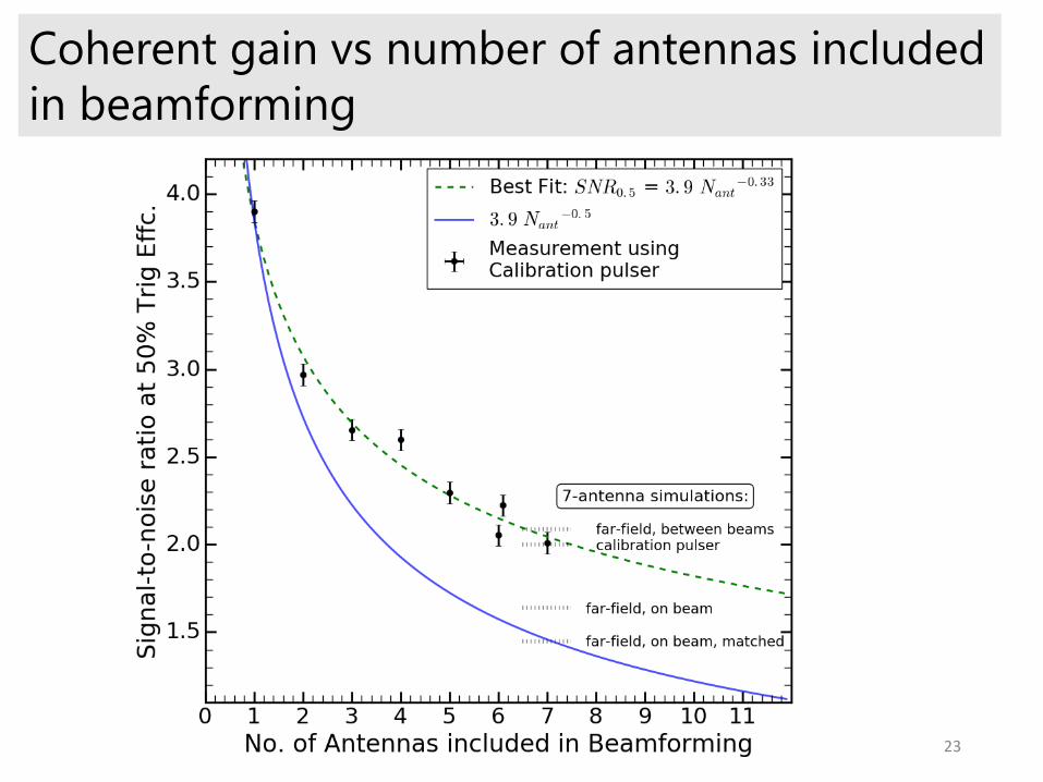
coherent gain scales as 𝑁𝑎𝑛𝑡𝑒𝑛𝑛𝑎 . Compact array: wide beams, fewer trials. Use to
trigger a separate optimized ‘reconstruction’ array
[simulated]Vpol 8-array beam pattern4-bit resolutionDownward beams only shown
interaction vertex
θ = 56⁰
Cherenkov cone~impulsive plane wave
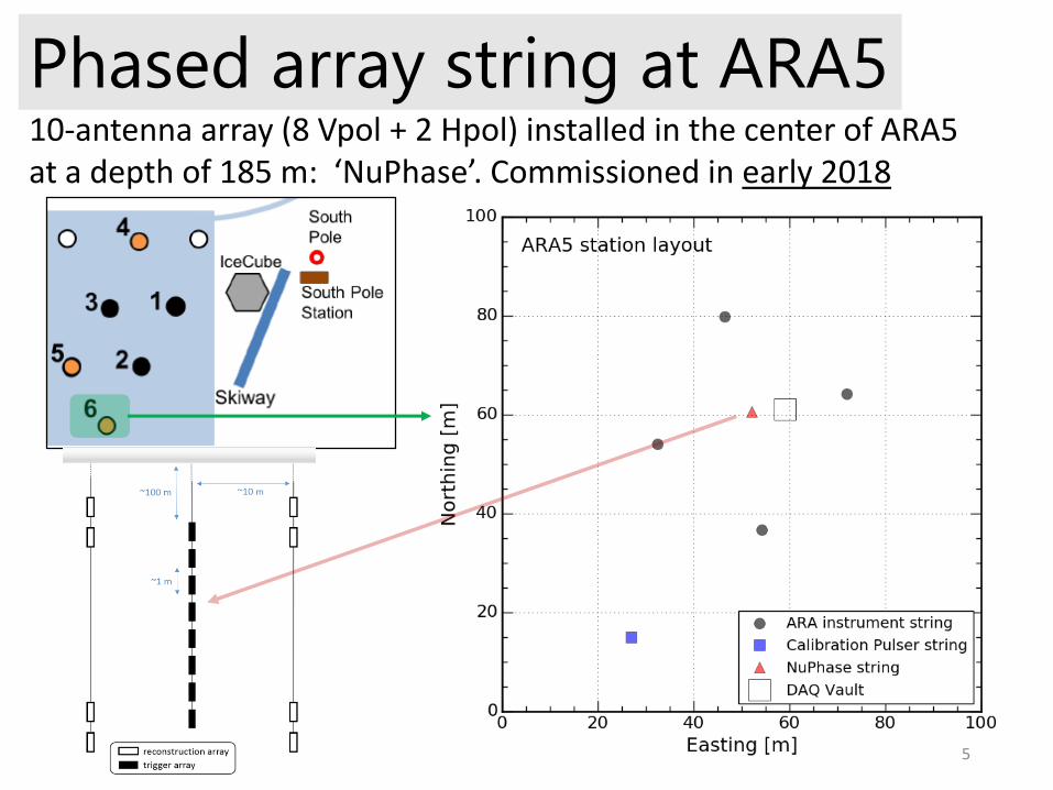
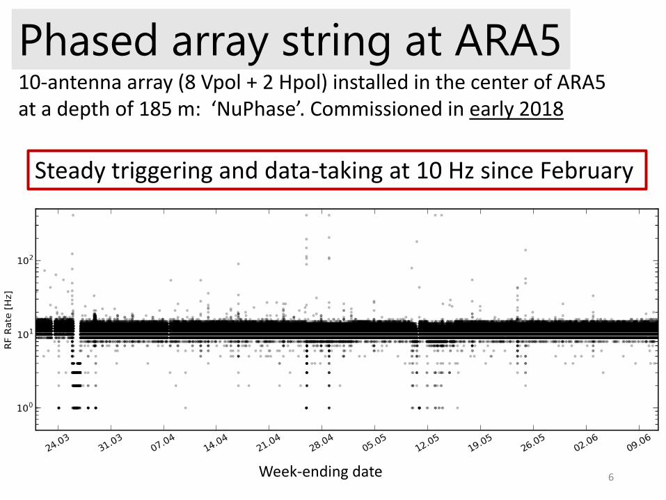
Phased array string at ARA510-antenna array (8 Vpol + 2 Hpol) installed in the center of ARA5 at a depth of 185 m: ‘NuPhase’. Commissioned in early 2018
5
Phased array string at ARA510-antenna array (8 Vpol + 2 Hpol) installed in the center of ARA5 at a depth of 185 m: ‘NuPhase’. Commissioned in early 2018
Steady triggering and data-taking at 10 Hz since February
Week-ending date 6
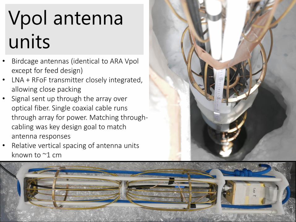
Vpol antenna
units• Birdcage antennas (identical to ARA Vpol
except for feed design)• LNA + RFoF transmitter closely integrated,
allowing close packing• Signal sent up through the array over
optical fiber. Single coaxial cable runs through array for power. Matching through-cabling was key design goal to match antenna responses
• Relative vertical spacing of antenna units known to ~1 cm
7

Fiber management
8
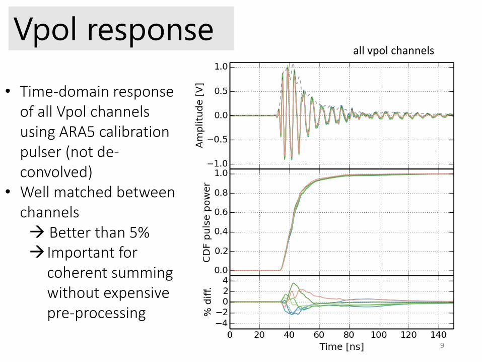
Vpol response
• Time-domain response of all Vpol channels using ARA5 calibration pulser (not de-convolved)
• Well matched between channels Better than 5% Important for
coherent summing without expensive pre-processing
all vpol channels
9
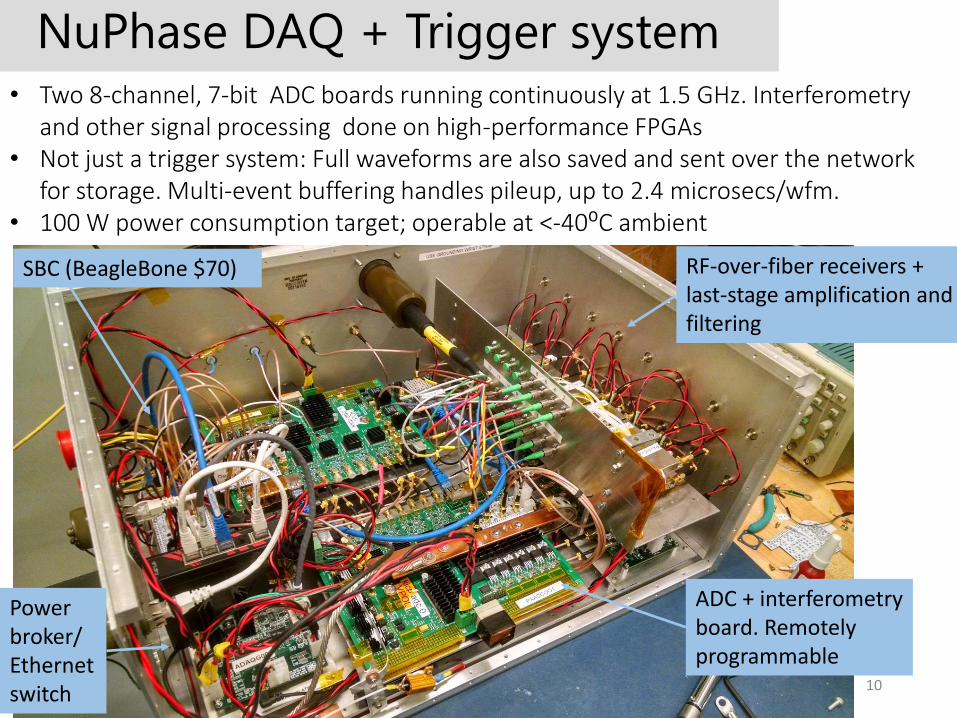
NuPhase DAQ + Trigger system• Two 8-channel, 7-bit ADC boards running continuously at 1.5 GHz. Interferometry
and other signal processing done on high-performance FPGAs• Not just a trigger system: Full waveforms are also saved and sent over the network
for storage. Multi-event buffering handles pileup, up to 2.4 microsecs/wfm. • 100 W power consumption target; operable at <-40⁰C ambient
RF-over-fiber receivers + last-stage amplification and filtering
ADC + interferometry board. Remotely programmable
Power broker/ Ethernet switch 10
SBC (BeagleBone $70)
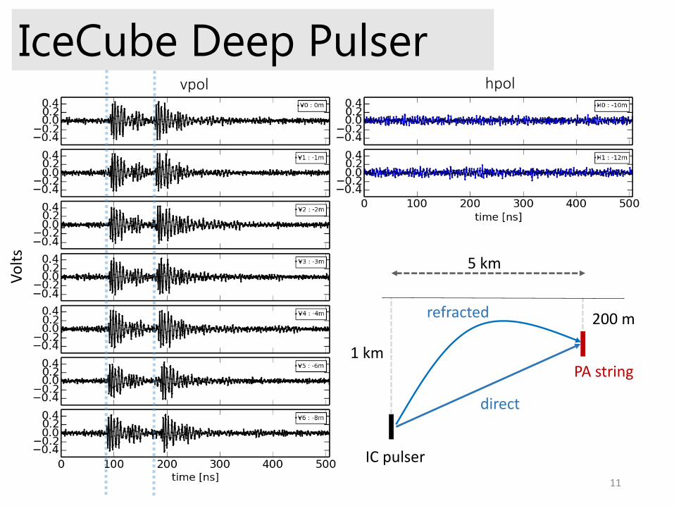
IceCube Deep PulserV
olt
s
1 km
200 m
5 km
IC pulser
PA string
vpol hpol
direct
refracted
11
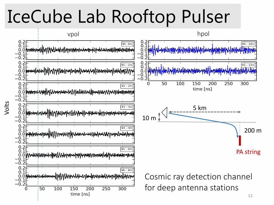
IceCube Lab Rooftop PulserV
olt
s
200 m
5 km
PA string
10 m
Cosmic ray detection channel for deep antenna stations
vpol hpol
12
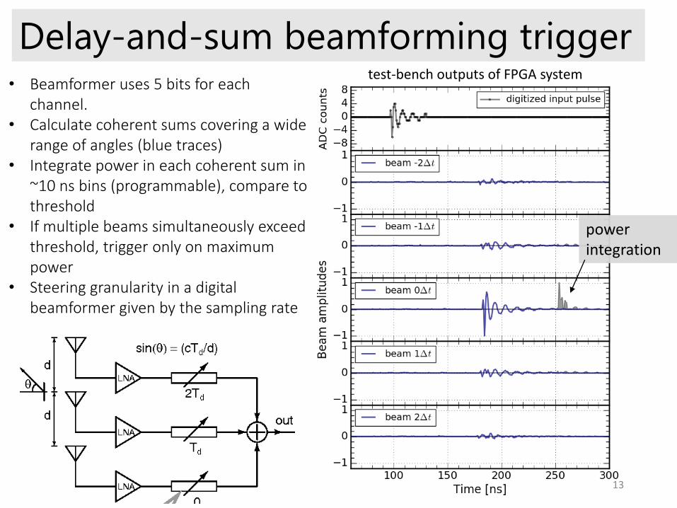
Delay-and-sum beamforming trigger• Beamformer uses 5 bits for each
channel. • Calculate coherent sums covering a wide
range of angles (blue traces)• Integrate power in each coherent sum in
~10 ns bins (programmable), compare to threshold
• If multiple beams simultaneously exceed threshold, trigger only on maximum power
• Steering granularity in a digital beamformer given by the sampling rate
power integration
test-bench outputs of FPGA system
13
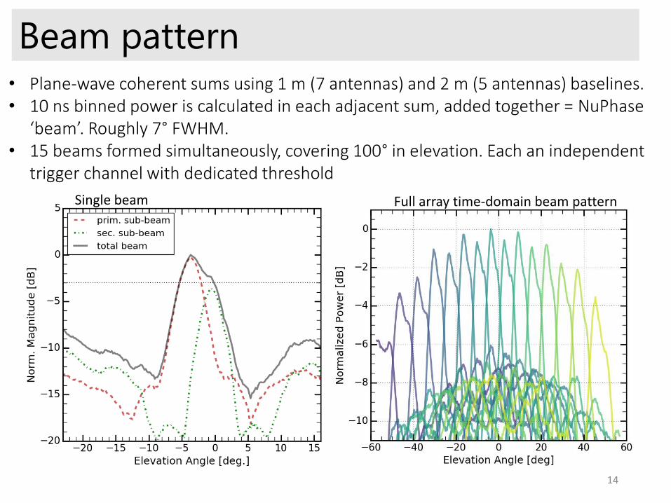
Beam pattern• Plane-wave coherent sums using 1 m (7 antennas) and 2 m (5 antennas) baselines.• 10 ns binned power is calculated in each adjacent sum, added together = NuPhase
‘beam’. Roughly 7° FWHM.• 15 beams formed simultaneously, covering 100° in elevation. Each an independent
trigger channel with dedicated threshold
Full array time-domain beam pattern
14
Single beam
Trigger Efficiency
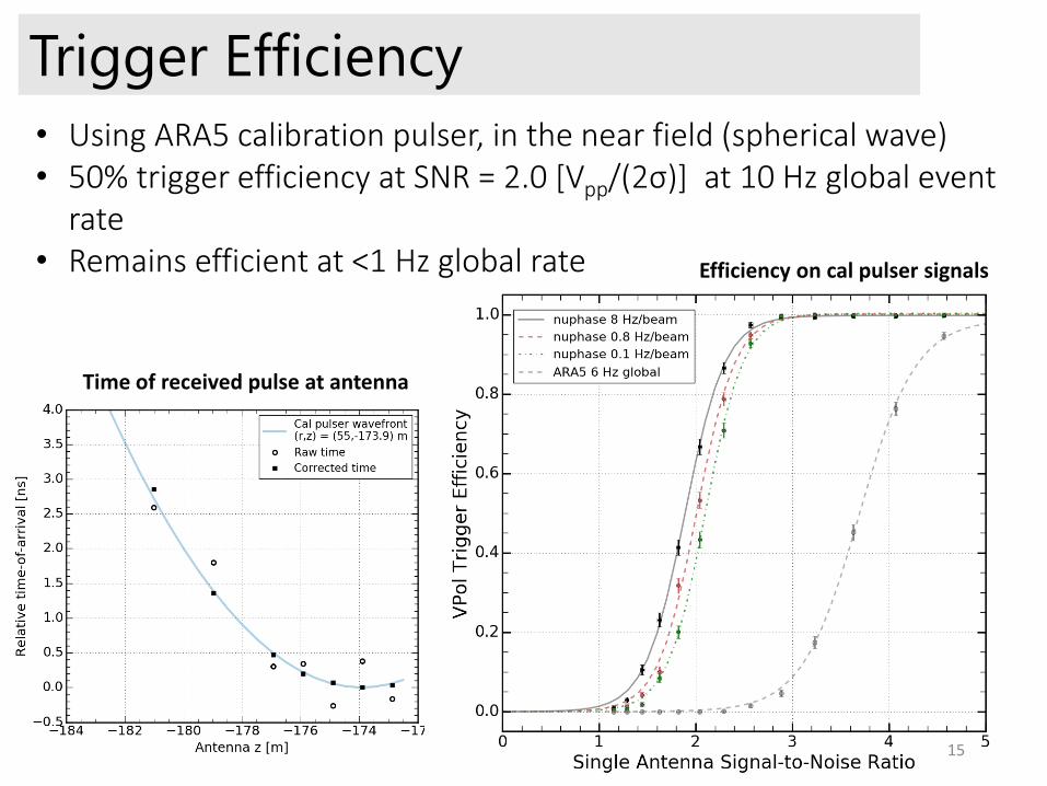
• Using ARA5 calibration pulser, in the near field (spherical wave)• 50% trigger efficiency at SNR = 2.0 [Vpp/(2σ)] at 10 Hz global event
rate• Remains efficient at <1 Hz global rate Efficiency on cal pulser signals
Time of received pulse at antenna
15

Detailed hardware-level simulation• Important to understand FPGA processing + array sensitivity as a function of
elevation angle and wavefront properties • Some dependence on elevation angle due to beam patterns. Trigger efficiency at
50% varies between 1.6 and 2.1 for far-field plane waves• Agrees well with measurements
Efficiency curves: nearby transmitter + far-field Incident angle dependence
16
Efficiency curves: nearby transmitter + far-field Incident angle dependence
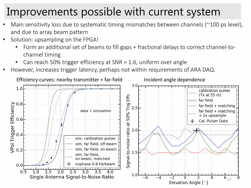
Improvements possible with current system• Main sensitivity loss due to systematic timing mismatches between channels (~100 ps level),
and due to array beam pattern • Solution: upsampling on the FPGA!
• Form an additional set of beams to fill gaps + fractional delays to correct channel-to-channel timing
• Can reach 50% trigger efficiency at SNR = 1.6, uniform over angle• However, increases trigger latency, perhaps not within requirements of ARA DAQ.
17
Scaling up?
18
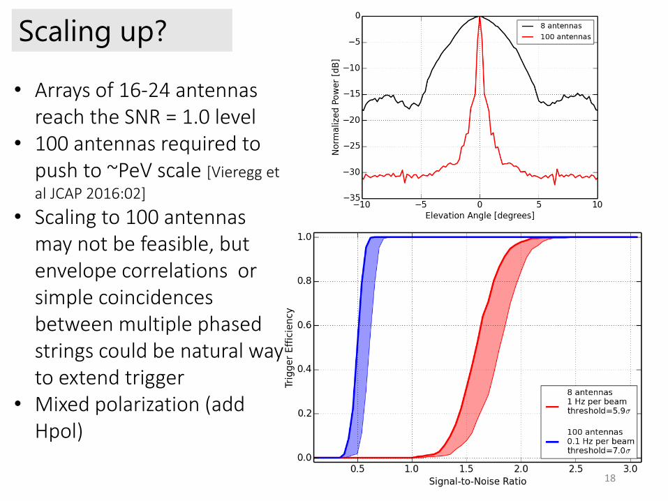
• Arrays of 16-24 antennas reach the SNR = 1.0 level
• 100 antennas required to push to ~PeV scale [Vieregg et
al JCAP 2016:02]
• Scaling to 100 antennas may not be feasible, but envelope correlations or simple coincidences between multiple phased strings could be natural way to extend trigger
• Mixed polarization (add Hpol)
19
Summary• Full phased array trigger system deployed at South Pole in
2017/18 season in collaboration with ARA• Trigger efficient on Vpol signals with SNR ≥ 2.0• Room for improvement in current system with additional
firmware features. • BEACON deployment will serve as testbed for further FPGA
development for RFI mitigation, etc. (see Stephanie Wissel talk)
• Path towards scaling up includes optimizing the antenna array (number, frequency, and polarization) and lowering power consumption for potential autonomous stations. • An 8-channel phased array possible within 15W?
• Streaming digitization, even at low resolution, is an asset to any radio detector
Backup
20
21
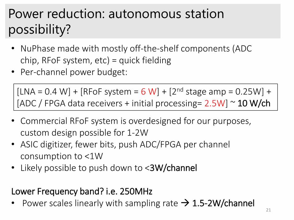
Power reduction: autonomous station
possibility?
• NuPhase made with mostly off-the-shelf components (ADC chip, RFoF system, etc) = quick fielding
• Per-channel power budget:
• Commercial RFoF system is overdesigned for our purposes, custom design possible for 1-2W
• ASIC digitizer, fewer bits, push ADC/FPGA per channel consumption to <1W
• Likely possible to push down to <3W/channel
Lower Frequency band? i.e. 250MHz• Power scales linearly with sampling rate 1.5-2W/channel
[LNA = 0.4 W] + [RFoF system = 6 W] + [2nd stage amp = 0.25W] + [ADC / FPGA data receivers + initial processing= 2.5W] ~ 10 W/ch
22
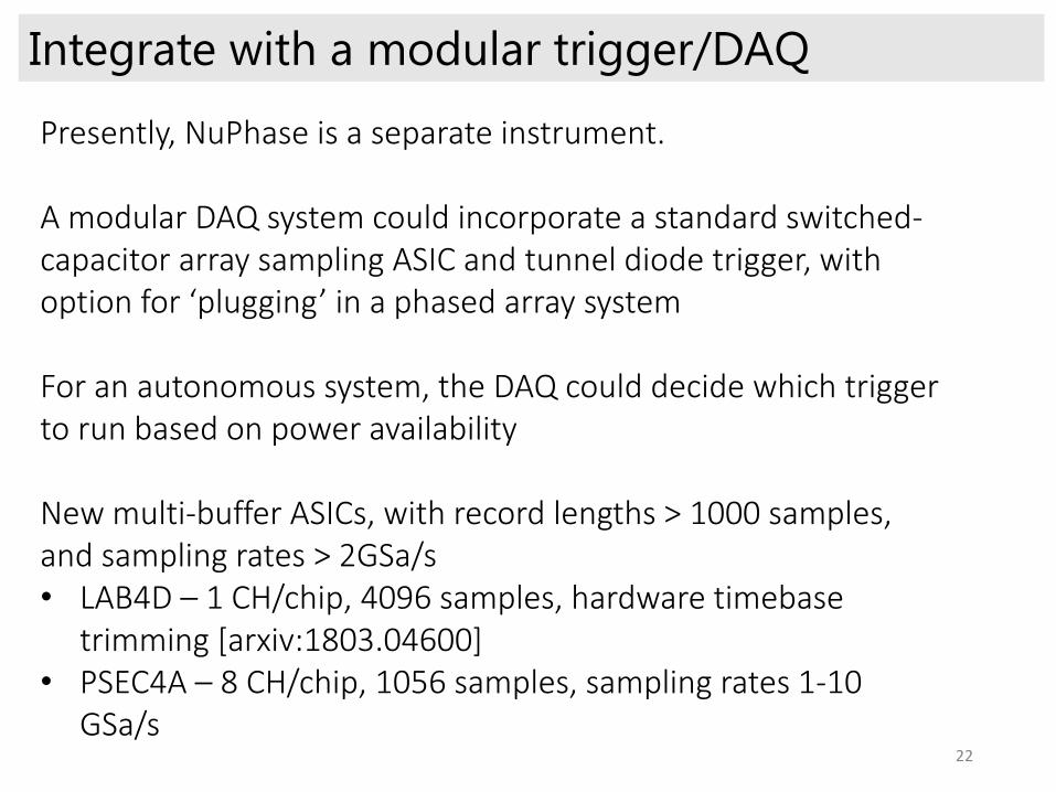
Integrate with a modular trigger/DAQ
Presently, NuPhase is a separate instrument.
A modular DAQ system could incorporate a standard switched-capacitor array sampling ASIC and tunnel diode trigger, with option for ‘plugging’ in a phased array system
For an autonomous system, the DAQ could decide which trigger to run based on power availability
New multi-buffer ASICs, with record lengths > 1000 samples, and sampling rates > 2GSa/s• LAB4D – 1 CH/chip, 4096 samples, hardware timebase
trimming [arxiv:1803.04600]• PSEC4A – 8 CH/chip, 1056 samples, sampling rates 1-10
GSa/s
23
Coherent gain vs number of antennas included
in beamforming
24
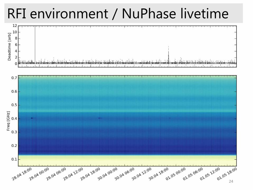
RFI environment / NuPhase livetime
25
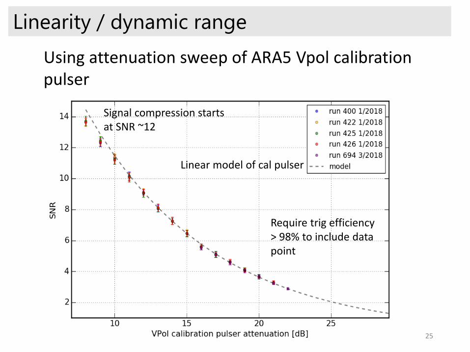
Linearity / dynamic range
Using attenuation sweep of ARA5 Vpol calibration pulser
Require trig efficiency > 98% to include data point
Linear model of cal pulser
Signal compression starts at SNR ~12
26
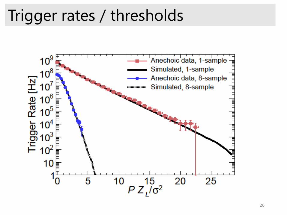
Trigger rates / thresholds
Top Related