


Languages
Pages
Legal


PVG 120Proportional Valves
Service Parts Manual
2 DKMH.PS.510.Q7.02 520L0247
PVG 120 Proportional ValveService Parts ManualContents and Data Survey
© 2001 Sauer-Danfoss
Sauer-Danfoss can accept no responsibility for possible errors in catalogues, brochures and other printed material. Sauer -Danfoss reserves the rightto alter its products without prior notice. This also applies to products already ordered provided that such alterations can be made without subsequentchanges being necessary in specifications already agreed. All trademarks in this material are properties of the respective companies. Sauer-Danfossand the Sauer-Danfoss logotype are trademarks of the Sauer-Danfoss Group. All rights reserved.
Frontpage: P300003.TIF, P300001.TIF, P300009.TIF, P30011.TIF, Drawing 155B570.ai
PageSectional drawing ............................................................................................................................................................. 3Identifi cation .......................................................................................................................................................................4Installation PVG................................................................................................................................................................. 5 Spare parts .................................................................................................................................................................... 22 Pos. 1: PVP, pump side module .................................................................................................................... 22 Pos. 2: PVP, accessories for pump side modules .................................................................................... 24 Pos. 3: PVB, basic module............................................................................................................................... 26 Pos. 4: PVLP/PVLA, shock and anti-cavitation valve ............................................................................. 28 Pos. 5: PVB, accessories for basic modules................................................................................................ 30 Pos. 6: PVM, mechanical activation ............................................................................................................. 32 Pos. 7: PVMD, cover for mechanical activation...................................................................................... 34 Pos. 8: PVH, cover for hydraulic activation.............................................................................................. 34 Pos. 9: PVEH, electrical activation............................................................................................................... 36 Pos. 10: PVEO, electrical activation............................................................................................................... 36 Pos. 11: PVT, tank side module, upper part ................................................................................................. 38 Pos. 12: PVT, tank side module, lower part .................................................................................................. 40 Pos. 13: PVGI, combi module............................................................................................................................ 42 Pos. 14: PVAS/PVGI, assemply kit .................................................................................................................. 44 Set of seal sets PVG 32 ......................................................................................................................................... 46
CONTENTS AND DATA SURVEY

3DKMH.PS.510.Q7.02 520L0247
PVG 120SECTIONAL DRAWING
COST-FREE REPAIRS
PVG 120 Proportional ValveService Parts ManualSectional drawing
1. Main spool 2. Pressure adjustment spool in PVP 3. Shuttle valve 4. Pressure relief valve in PV 5. Pressure compensator in PVB 6. LS-pressure relief valve in PVB 7. Shock and suction valve 8. Suction valve 9. PVP, orifi ce, closed center PVP, plug, open centre 10. LS-connection 11. PVP, orifi ce, open centre 12. PVP, plug, closed centre
We would point out that cost-free repairs as mentioned in Sauer-Danfoss General Conditions of Sale, are carried out only at Sauer-Danfoss or at service shops authorized by Sauer-Danfoss.

4 DKMH.PS.510.Q7.02 520L0247
IDENTIFICATION
PVG 120 Proportional ValveService Parts ManualIdentifi cation
C: PVG – number, week and year of installationD: PVP – pressure settingE: PVP – number, week, year and day manufacturing, issue and series No.F: PVB – A-Port, number, week, year and day manufacturing, issue and series No.G: PVT – week and year of manufacturing

5DKMH.PS.510.Q7.02 520L0247
INSTALLATION AND PLUG ORIENTATION
PVG 120 Proportional ValveService Parts ManualInstallation
* Room for dismantling
Module of PVB 1 2 3 4 5 6 7 8L mm 168 235 302 369 436 503 570 637
L in 6.61 9.25 11.88 14.53 17.17 19.80 22.44 25.08

6 DKMH.PS.510.Q7.02 520L0247
PVG 120 Proportional ValveService Parts ManualInstallation
CONNECTION, PVP, PUMP SIDE MODULE

7DKMH.PS.510.Q7.02 520L0247
PVG 120 Proportional ValveService Parts ManualInstallation
OIL FLOW DIRECTION Mechanical actuation/electrical
Mechanical/hydraulic actuation

8 DKMH.PS.510.Q7.02 520L0247
PVG 120 Proportional ValveService Parts ManualInstallation
TIGHTENING TORQUES
CONNECTION THREADS TYPE G (ISO 228/1)
MOUNTING THREADS IN SAE J 518C FLANGES
UN AND UNF CONNECTION THREADS – O-RING BOSS PORT
Max. tightening torques PA, PB MA LS, LX, PP
Sealing Thread G 1/4 G 1/4 G 3/8
with steel washer 35 Nm [310 lbf·in] 40 Nm [350 lbf·in] 60 Nm [530 lbf·in]
With cooper washer 30 Nm [270 lbf·in] 20 Nm [180 lbf·in] 35 Nm [310 lbf·in]
with aluminium washer 30 Nm [270 lbf.in] 30 Nm [270 lbf.in] 40 Nm [350 lbf·in]
with cutting edge 35 Nm [310 lbf.in] 40 Nm [350 lbf.in] 60 Nm [530 lbf·in]
Max. tightening torques Port Size Threads Tightening torque
M12, 18 deep 68 Nm
P 1 in
7/16 - 14 UNC 0.7” deep [600 lbf·in]
M10, 17 deep 45 Nm
A/B 3/4 in
3/8 - 16 UNC 0.7” deep [400 lbf·in]
M10, 17 deep 45 Nm
T 1 in
3/8 - 16 UNC 0.7” deep [400 lbf·in]
Max. tightening torques P A/B T PA/PB MA LS,LX,PP
Sealing / Thread 1 5/16 in-12 UN 1 1/16 in-12 UN 1 5/16 in-12 UN 1/2 in-20 UNF 1/2 in-20 UNF 3/4 in-20 UNF
O-ring 160 Nm 120 Nm 160 Nm 30 Nm 30 Nm 60 Nm
[1410 in-lbs] [1060 in-lbs] [1410 in-lbs] [270 in-lbs] [270 in-lbs] [530 in-lbs]

9DKMH.PS.510.Q7.02 520L0247
PVG 120 Proportional ValveService Parts ManualInstallation
INSTALLATION OF LEVER
SETTING OF MAX. FLOW
Base with an angle of 22.5° Base with an angle of 37.5°

10 DKMH.PS.510.Q7.02 520L0247
PVG 120 Proportional ValveService Parts ManualInstallation
PRESSURE SETTING
PVP, LS RELIEF VALVE SETTING
PVB, LS RELIEF VALVE SETTING
11DKMH.PS.510.Q7.02 520L0247
PVG 120 Proportional ValveService Parts ManualInstallation
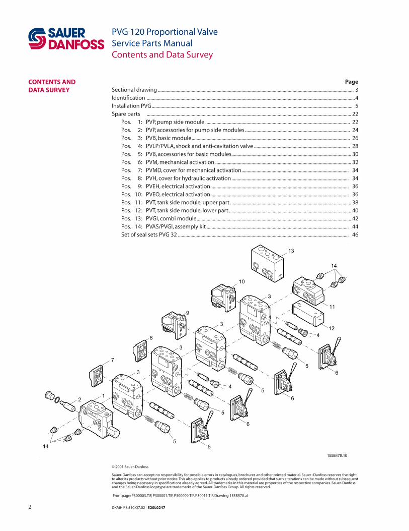
ELECTRICAL ACTUATING MODULE PVE SERIES 2 FOR PVG 120
Oil fl ow direction

12 DKMH.PS.510.Q7.02 520L0247
Electrical connection
Proportional activation
On/off activation
25 Pin SUB-D connector with M3 screws (MIL-DTL-24308)
E: Emergency circuit brakerF: Branch circuit for fault indication
PVG 120 Proportional ValveService Parts ManualInstallation
OPTION, OIL FLOW DIRECTION AND SETTING OF MAX FLOW UDC 11 - 15 V ––
__ 22 - 30 V ––__
Pin 1 (U+) 2 (US) 1 (U+) 2 (US)
Q: P → A UDC (0.5 → 0.25) × UDC UDC (0.5 → 0.25) × UDC
Q: P → B UDC (0.5 → 0.75) × UDC UDC (0.5 → 0.75) × UDC
Neutral UDC 0.5 × UDC UDC 0.5 × UDC
UDC 11 - 15 V ––__ 22 - 30 V ––
__ Pin 1 (A) 2 (B) 1 (A) 2 (B)
Q: P → A UDC 0 UDC 0
Q: P → B – UDC – (UDC
Neutral 0 0 0 0
UDC = Supply voltageUS = Signal voltage
13DKMH.PS.510.Q7.02 520L0247
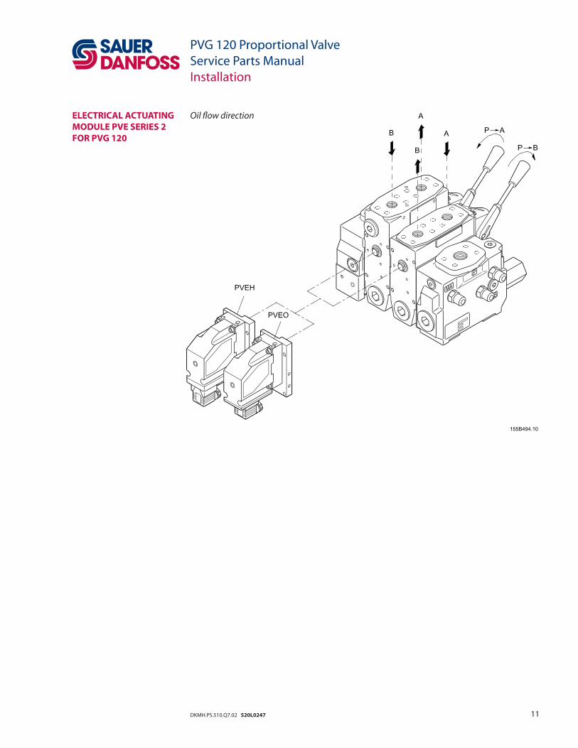
PVE FAULT MONITORING
PVG 120 Proportional ValveService Parts ManualInstallation
Normal
Green A: External relay B: Solenoid valve
Fault
Red A: External relay B: Solenoid valve
14 DKMH.PS.510.Q7.02 520L0247
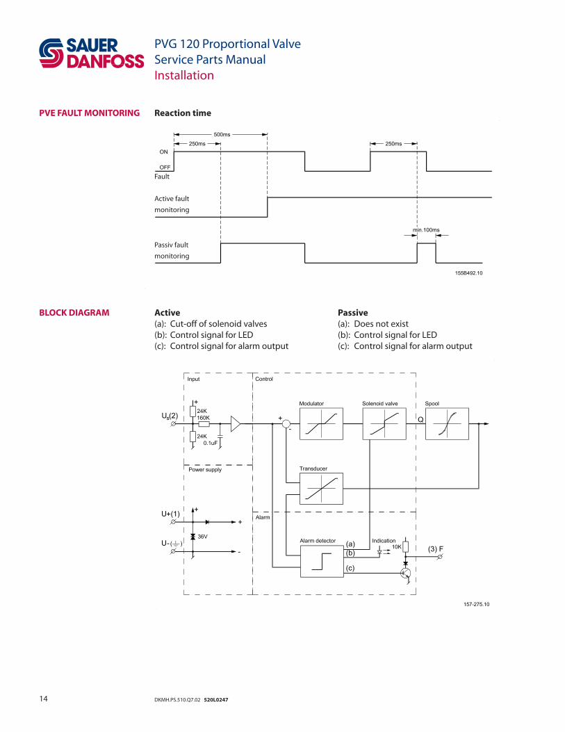
Reaction time
Fault
Active fault
monitoring
Passiv fault
monitoring
Active Passive (a): Cut-off of solenoid valves (a): Does not exist (b): Control signal for LED (b): Control signal for LED(c): Control signal for alarm output (c): Control signal for alarm output
PVE FAULT MONITORING
BLOCK DIAGRAM
PVG 120 Proportional ValveService Parts ManualInstallation

15DKMH.PS.510.Q7.02 520L0247
PVEH
ADJUSTMENT OF PVE WHEN MAX. LEVER TRAVEL IS EXCEEDED (PVE IS FACTORY-PRESET)
PVG 120 Proportional ValveService Parts ManualInstallation
Check max. lever travel in neutral position1. Make sure the system is supplied with hydraulic power2. Connect supply voltage (UDC) (Signal voltage = 0,5 × UDC), or cut off the signal voltage (US) on pin 2.
Lever travel exceeded in PVG 32 Direction of rotation for adjustment of position transducer
Direction A
Direction B
Turn of transducer Movement of lever 1⁄4 1.5 mm [0.06 in]
1⁄2 3.0 mm [0.12 in]
3⁄4 4. 5 mm [0.18 in]

16 DKMH.PS.510.Q7.02 520L0247
For security reasons, any replacement of O-rings between valve block 1 and intermediate plate 2 may only be effected at service shops authorized by Danfoss.
Mixing up PVE series 2 for PVG 120 and PVG 32 may lead to self-actuation.
PVEH
PVEO
INSTALLATION OF PVE
PVG 120 Proportional ValveService Parts ManualInstallation

17DKMH.PS.510.Q7.02 520L0247
BLEEDING
PVG 120 Proportional ValveService Parts ManualInstallation
(If the group is installed vertically, it is recommended to bleed it at the adjusting screws)

18 DKMH.PS.510.Q7.02 520L0247
PVPE/PVH,RELIEF VALVES
PVPH AND LS CONNECTIONS
PVG 120 Proportional ValveService Parts ManualInstallation
Position Across fl ats Max. tightening torque
1 22 mm 5 Nm
[0.87 in] [45 lbf·in]
2 36 mm 85 Nm
[1.42 in] [750 lbf·in]
3
36 mm 85 Nm
[1.42 in] [750 lbf·in]
Sealing Steel washer Cupper washer Aluminium washer Cutting edge
Threads, PVPH: LS: PVPH: LS: PVPH: LS: PVPH: LS:
DS/ISO 228/1 G 1/4 G 3/8 G 1/4 G 3/8 G 1/4 G 3/8 G 1/4 G 3/8
Max. tightening 40 Nm 60 Nm 20 Nm 35 Nm 30 Nm 40 Nm 40 Nm 60 Nm
torque (350 lbf·in) (530 lbf·in) (180 lbf in) (310 lbf·in) (270 lbf in) (350 lbf·in) (350 lbf·in) (530 lbf·in)
19DKMH.PS.510.Q7.02 520L0247
PVPE , TECHNICAL DATA
CONNECTION PVPE
PVG 120 Proportional ValveService Parts ManualInstallation
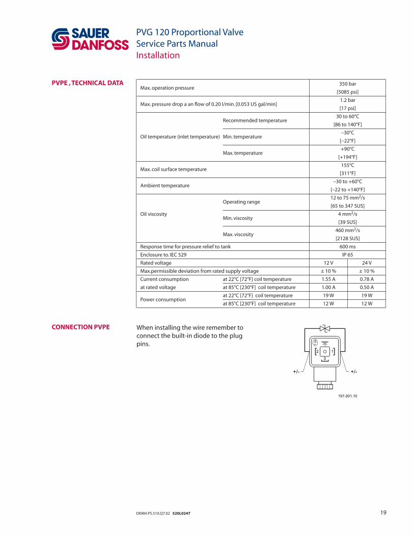
Max. operation pressure 350 bar
[5085 psi]
Max. pressure drop a an fl ow of 0.20 l/min. [0.053 US gal/min] 1.2 bar
[17 psi]
Recommended temperature
30 to 60°C
[86 to 140°F]
Oil temperature (inlet temperature) Min. temperature –30°C
[–22°F]
Max. temperature
+90°C
[+194°F]
Max. coil surface temperature 155°C
[311°F]
Ambient temperature –30 to +60°C
[–22 to +140°F]
Operating range
12 to 75 mm2/s
[65 to 347 SUS]
Oil viscosity Min. viscosity
4 mm2/s
[39 SUS]
Max. viscosity
460 mm2/s
[2128 SUS]
Response time for pressure relief to tank 600 ms
Enclosure to. IEC 529 IP 65
Rated voltage 12 V 24 V
Max.permissible deviation from rated supply voltage ± 10 % ± 10 %
Current consumption at 22°C [72°F] coil temperature 1.55 A 0.78 A
at rated voltage at 85°C [230°F] coil temperature 1.00 A 0.50 A
Power consumption at 22°C [72°F] coil temperature 19 W 19 W
at 85°C [230°F] coil temperature 12 W 12 W
When installing the wire remember to connect the built-in diode to the plug pins.

20 DKMH.PS.510.Q7.02 520L0247
WIRING EXAMPLE
PVG 120 Proportional ValveService Parts ManualInstallation
*1) In order not to be interpreted as defect, unused inputs must be connected to minus.
PVG 120 with normally open PVPE, PVRE remote control lever and EHA electronic alarm logic

21DKMH.PS.510.Q7.02 520L0247
NOTES
PVG 120 Proportional ValveService Parts ManualNotes
22 DKMH.PS.510.Q7.02 520L0247
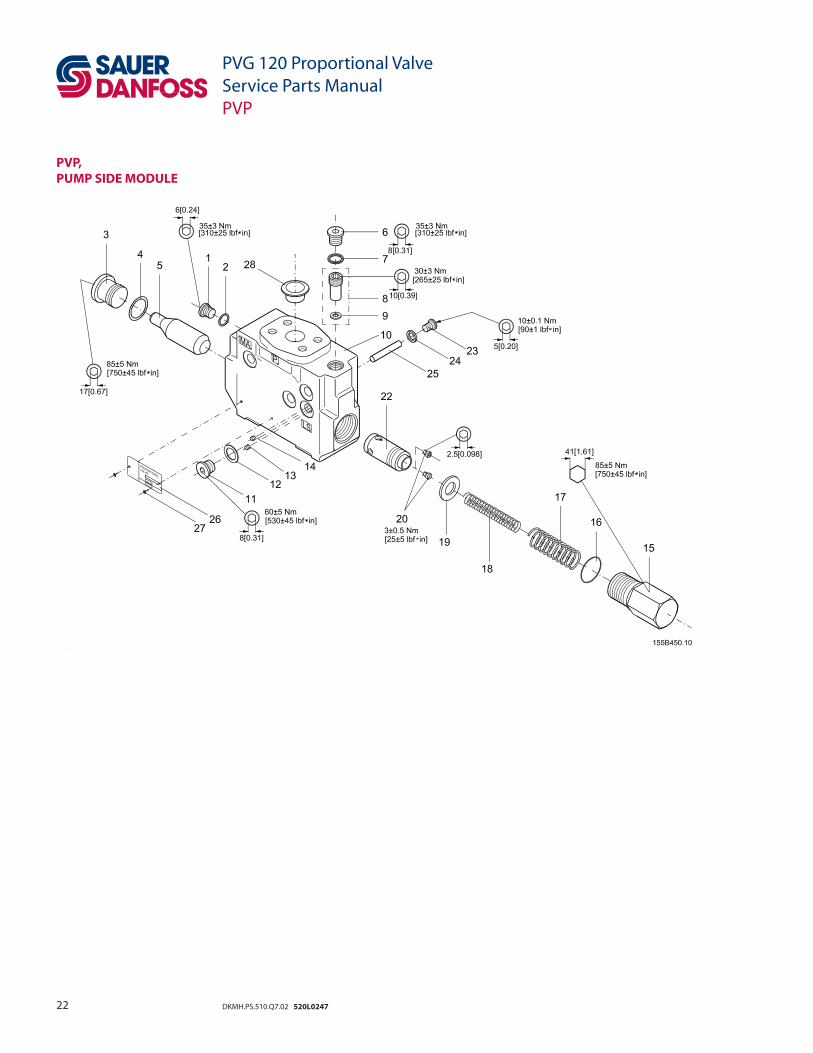
PVP, PUMP SIDE MODULE
PVG 120 Proportional ValveService Parts ManualPVP
23DKMH.PS.510.Q7.02 520L0247
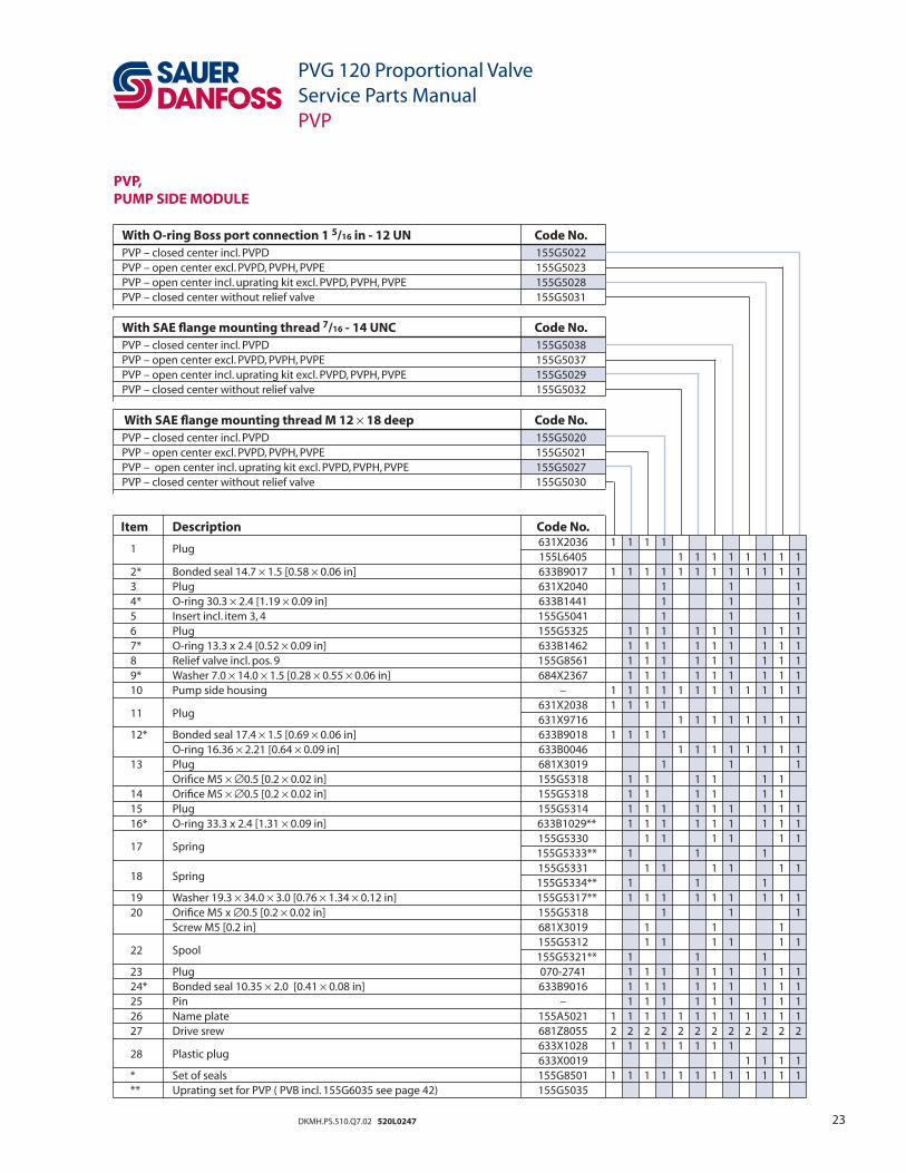
PVP, PUMP SIDE MODULE
PVG 120 Proportional ValveService Parts ManualPVP
Item Description Code No.
1 Plug 631X2036 1 1 1 1
155L6405 1 1 1 1 1 1 1 1 2* Bonded seal 14.7 × 1.5 [0.58 × 0.06 in] 633B9017 1 1 1 1 1 1 1 1 1 1 1 1 3 Plug 631X2040 1 1 1 4* O-ring 30.3 × 2.4 [1.19 × 0.09 in] 633B1441 1 1 1 5 Insert incl. item 3, 4 155G5041 1 1 1 6 Plug 155G5325 1 1 1 1 1 1 1 1 1 7* O-ring 13.3 x 2.4 [0.52 × 0.09 in] 633B1462 1 1 1 1 1 1 1 1 1 8 Relief valve incl. pos. 9 155G8561 1 1 1 1 1 1 1 1 1 9* Washer 7.0 × 14.0 × 1.5 [0.28 × 0.55 × 0.06 in] 684X2367 1 1 1 1 1 1 1 1 1 10 Pump side housing – 1 1 1 1 1 1 1 1 1 1 1 1
11 Plug 631X2038 1 1 1 1
631X9716 1 1 1 1 1 1 1 1 12* Bonded seal 17.4 × 1.5 [0.69 × 0.06 in] 633B9018 1 1 1 1 O-ring 16.36 × 2.21 [0.64 × 0.09 in] 633B0046 1 1 1 1 1 1 1 1 13 Plug 681X3019 1 1 1 Orifi ce M5 × ∅0.5 [0.2 × 0.02 in] 155G5318 1 1 1 1 1 1 14 Orifi ce M5 × ∅0.5 [0.2 × 0.02 in] 155G5318 1 1 1 1 1 1 15 Plug 155G5314 1 1 1 1 1 1 1 1 1 16* O-ring 33.3 x 2.4 [1.31 × 0.09 in] 633B1029** 1 1 1 1 1 1 1 1 1
17 Spring 155G5330 1 1 1 1 1 1
155G5333** 1 1 1
18 Spring 155G5331 1 1 1 1 1 1
155G5334** 1 1 1 19 Washer 19.3 × 34.0 × 3.0 [0.76 × 1.34 × 0.12 in] 155G5317** 1 1 1 1 1 1 1 1 1 20 Orifi ce M5 x ∅0.5 [0.2 × 0.02 in] 155G5318 1 1 1 Screw M5 [0.2 in] 681X3019 1 1 1
22 Spool 155G5312 1 1 1 1 1 1
155G5321** 1 1 1 23 Plug 070-2741 1 1 1 1 1 1 1 1 1 24* Bonded seal 10.35 × 2.0 [0.41 × 0.08 in] 633B9016 1 1 1 1 1 1 1 1 1 25 Pin – 1 1 1 1 1 1 1 1 1 26 Name plate 155A5021 1 1 1 1 1 1 1 1 1 1 1 1 27 Drive srew 681Z8055 2 2 2 2 2 2 2 2 2 2 2 2
28 Plastic plug 633X1028 1 1 1 1 1 1 1 1
633X0019 1 1 1 1 * Set of seals 155G8501 1 1 1 1 1 1 1 1 1 1 1 1 ** Uprating set for PVP ( PVB incl. 155G6035 see page 42) 155G5035
With O-ring Boss port connection 1 5/16 in - 12 UN Code No.PVP – closed center incl. PVPD 155G5022 PVP – open center excl. PVPD, PVPH, PVPE 155G5023 PVP – open center incl. uprating kit excl. PVPD, PVPH, PVPE 155G5028 PVP – closed center without relief valve 155G5031
With SAE fl ange mounting thread 7/16 - 14 UNC Code No.PVP – closed center incl. PVPD 155G5038 PVP – open center excl. PVPD, PVPH, PVPE 155G5037 PVP – open center incl. uprating kit excl. PVPD, PVPH, PVPE 155G5029 PVP – closed center without relief valve 155G5032
With SAE fl ange mounting thread M 12 × 18 deep Code No.PVP – closed center incl. PVPD 155G5020 PVP – open center excl. PVPD, PVPH, PVPE 155G5021 PVP – open center incl. uprating kit excl. PVPD, PVPH, PVPE 155G5027 PVP – closed center without relief valve 155G5030

24 DKMH.PS.510.Q7.02 520L0247
PVPD, PVPH, PVPE,ACCESSORIES FOR PVP
PVG 120 Proportional ValveService Parts ManualPVPE, PVPD and PVPH

25DKMH.PS.510.Q7.02 520L0247
PVPE, PVPD AND PVPH (ADDITIONAL MODULE FOR PVP OPEN CENTER)
PVG 120 Proportional ValveService Parts ManualPVPE, PVPD and PVPH
Type Code No.
PVPE – extra electrical relief valve 12 V 155G5052
24 V 155G5054
PVPD – Plug 155G5041
PVPH – extra hydraulic relief valve 155G5061
Item Description Code No. 1 Electrical plug 155G5451 1 1
2 Electrical relief valve incl. item 3, 4, 5
155G5013 1
155G5025 1
3* O-ring 29.82 × 2.62 [1.18 × 0.10 in] 633B0069 1 1
4* Back-up ring 27.0 × 2.0 [1.06 × 0.08 in] 633B0068 1 1
5* O-ring 26.7 × 1.78 [1.05 × 0.07 in] 633B0070 1 1
6 Spring 155G5332 1 1
7 Orifi ce M5 × ∅0.5 [0.2 × 0.02 in] 155G5318 2 2 2
8 Spool 155G5311 1 1 1
9 Plug 631X2040 1
10* O-ring 30 × 3 × 2.4 [1.18 × 0.09 in] 633B1441 1 1
11 Insert incl. item 9, 10 155G5041 1
12 Plastic plug 633X7018
13 Nut 155G5404 2
14 Bushing 155G5403 1
15* Back-up ring 155G2316 1
16* O-ring 25.3 × 2.4 [1.0 × 0.09 in] 633B1440 1
17 Spool 155G5405 1
18 Cone 155G5406 1
19 Seat 155B4478 1
20 Spring 155G3317 1
* Set of seals
155G8527 1 1
155G8526 1

26 DKMH.PS.510.Q7.02 520L0247
PVB,BASIC MODULE
PVG 120 Proportional ValveService Parts ManualPVB

27DKMH.PS.510.Q7.02 520L0247
PVG 120 Proportional ValveService Parts ManualPVB
PVB,BASIC MODULE
SAE, UNC SAE fl ange mounting thread 3/8 - 16 UNC Code No.PVB high 155G6007
PVB low 155G6016
Item Description Code No. 1 Plastic plug 633X1029 2 2
633X7027 2
2 Plug 155B6508 1 1 1
3* O-ring 8.0 × 2.0 [0.35 × 0.08 in] 633B1056 1 1 1
4* O-ring 6.0 × 2.0 [0.24 × 0.08 in] 633B1460 1 1 1
5 Ball ∅6.0 [0.24 in] 689X1007 1 1 1
6 Plug 631X2040 1 1 1
7* O-ring 30.3 × 2.4 [1.19 × 0.09 in] 633B1441 1 1 1
8 Compensating spool 155G8530 1 1 1
9 Screw M6 × 10 [0.24 × 0.39 in] 681X1607 1 1 1
10 Bonded seal 6.7 × 1.0 [0.26 × 0.04 in] 633B9008 1 1 1
11 Orifi ce M6 x ∅0.6 [0.24 × 0.02 in] 155B8316 1 1 1
12 PVB housing – 1 1 1
13 Main spool – 1 1 1
* Set of seals 155G8502 1 1 1
SUN O-ring Boss port connection 1 1/16 - 12 UN Code No.PVB high 155G6006
PVB low 155G6015
With SAE fl ange mounting thread M 12 x 17 deep Code No.PVB high 155G6005
PVB low 155G6014

28 DKMH.PS.510.Q7.02 520L0247
PVG 120 Proportional ValveService Parts ManualPVLP / PVLA
PVLP / PVLA,SHOCK AND SUCTION VALVE PORT A/B

29DKMH.PS.510.Q7.02 520L0247
PVLP / PVLA,SHOCK AND SUCTION VALVE PORT A/B
PVG 120 Proportional ValveService Parts ManualPVLP / PVLA
Item Description Code No. 14 Plug 155G1386 1 1
15* Back-up ring 633B0014 1 1
16* Back-up ring 633B0016 1 1
17* O-ring 20.35 x 1.78 [0.80 × 0.07 in] 633B0015 1 1
PVLP 50 bar [725 psi] 155G0051 1
PVLP 75 bar [1087 psi] 155G0076 1
PVLP 100 bar [1450 psi] 155G0101 1
PVLP 125 bar [1813 psi] 155G0126 1
PVLP 150 bar [2175 psi] 155G0151 1
PVLP 175 bar [2538 psi] 155G0176 1
PVLP 200 bar [2900 psi] 155G0201 1
18 PVLP 225 bar [3263 psi] 155G0226 1
PVLP 250 bar [3625 psi] 155G0251 1
PVLP 275 bar [3988 psi] 155G0276 1
PVLP 300 bar [4351 psi] 155G0301 1
PVLP 325 bar [4713 psi] 155G0326 1
PVLP 350 bar [5076 psi] 155G0351 1
PVLP 375 bar [5438 psi] 155G0376 1
PVLP 400 bar [5801 psi] 155G0401 1
19 Plastic plug to protect cartridge 633X0053 1
20 Spring 155G1387 1 1
21 PVLA 155G1066 1
* Set of seals 155G8525 1 1
Type Code No.PVLP, setting pressure 50, 75, 100, 125, 175,
155G0....
200, 225, 250, 275, 300, 325, 350, 375, 400 bar
PVLP, setting pressure 725, 1087, 1450, 1813, 2538, 155G0....
2900, 3263, 3625, 3988, 4351, 4713, 5076, 5438, 5801 psi
PVLA 155G1065
30 DKMH.PS.510.Q7.02 520L0247
PVG 120 Proportional ValveService Parts ManualPVBP, PVBR, PVBC, PVBU
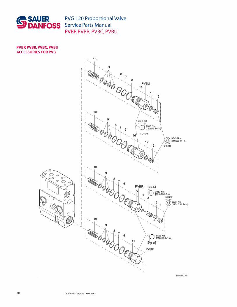
PVBP, PVBR, PVBC, PVBU ACCESSORIES FOR PVB

31DKMH.PS.510.Q7.02 520L0247
PVG 120 Proportional ValveService Parts ManualPVBP, PVBR, PVBC, PVBU
PVBP, PVBR, PVBC, PVBU ACCESSORIES
Type Code No.PVBU - uprating kit for PVB 155G6035
PVBR - LSA/B relief valve 155G6080
PVBP - plug 155G6081
PVBC - connection for external LS-signal 155G6082
Item Description Code No. 1 Plug 155G5325 1
2* O-ring 13.3 × 2.4 [0.52 × 0.09 in] 633B1462 1
3 Relief valve incl. item 4 155G8561 1
4* Washer 7.0 × 14.0 × 1.5 [0.28 × 0.55 × 0.06 in] 684X2367 1
5 Plug 155G2313 1
6* O-ring 30.3 × 2.4 [1.19 × 0.09 in] 633B1441 1 1 1 1
7* Back-up ring 155G2316 1 1 1 1
8* O-ring 25.3 × 2.4 [1.0 × 0.09 in] 633B1440 1 1 1 1
9 Adjustment disc. 155G2315 3 3 3 4
10 Spring 155G2317 1 1 1
11 Plug 155G2322 1
12 Plug 631X2036 1 1
13 Bonded seal 14.7 × 1,5 [0.58 × 0.06 in] 633B9017 1
14 Plug 155G2323 1
15 Spring 155G2324 1
16 Plug 155G2319 1
17 Washer 13.5 × 17.5 × 1.5 [0.53 × 0.69 × 0.06 in] 684X2120 1
* Set of seals 155G8502 1 1 1 1
32 DKMH.PS.510.Q7.02 520L0247
PVM, MECHANICAL ACTIVATING MODULE
PVG 120 Proportional ValveService Parts ManualPVM

33DKMH.PS.510.Q7.02 520L0247
PVG 120 Proportional ValveService Parts ManualPVM
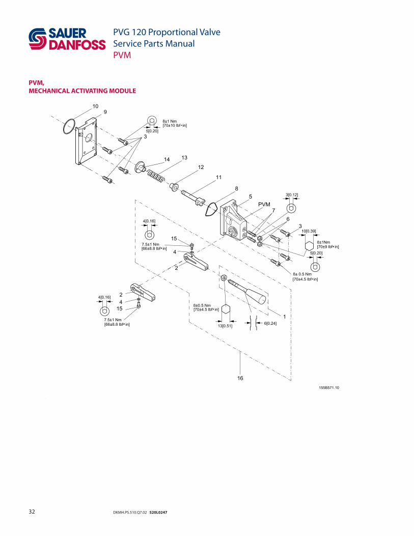
PVM, MECHANICAL ACTIVATING MODULE
Type Code No.PVM + PVMD 22.5° 155G3040
PVM + PVE 37.5° 155G3041
PVM + PVH 22.5° 155G3050
37.5° 155G3051
Item Description Code No. 1 Lever 155L3151 1 1 1 1
2 Base
22.5° 155L3450 1 1
37.5° 155L3451 1 1
3 Screw M6 × 20 [0.24 × 0.78 in] 681X9266 8 8 8 8
4 Washer 684X0075 1 1 1 1
5 PVM housing 155L3431 1 1 1 1
6* Seal nut M6 681X8270 2 2 2 2
7 Threaded pin M6 × 25 [0.80 × 0.07 in] 681X0323 2 2 2 2
8* Profi le O-ring 155L3430 1 1 1 1
9 Intermediate plate 155G3301 1 1 1 1
10* O-ring 42.0 × 2.0 [1.65 × 0.08 in] 633B1005 1 1 1 1
11 Spool control pin 155G3313 1 1 1 1
12 Stop 155G3314 1 1 1 1
13 Spring
155G3317 1 1
155G3316 1 1
14 Stop 155G3315 1 1 1 1
15 Screw 681X9289 1 1 1 1
16 Base (22.5°) and activation bar with knob and nut 155L3154
* Set of seals 155G8518

34 DKMH.PS.510.Q7.02 520L0247
PVMD, COVER FOR PVM
PVH, HYDRAULIC ACTIVATION
PVG 120 Proportional ValveService Parts ManualPVMD and PVH

35DKMH.PS.510.Q7.02 520L0247
PVMD, COVER FOR PVM
PVH, HYDRAULIC ACTIVATION
Type Code No.PVM + PVH assy - UNF 155G4021
PVH assy - BSP.F - thread 155G4022
PVMD assy 155G4061
Item Description Code No. 17 Screw M6 × 25 [0.80 × 0.07 in] 681X1198 4 4 4
18 Plastic plug
633X7018 2
633X0018 2
19 Cover
155G4301 1
155G4201 1
20* O-ring 6.0 × 2.0 [0.24 × 0.78 in] 633B1460 4 4 4
21* O-ring 27.0 × 2.0 [1.06 × 0.78 in] 633B0407 1 1 1
22 Cover 155G4402 1
* Set of seals 155G8505 1 1 1
PVG 120 Proportional ValveService Parts ManualPVMD and PVH

36 DKMH.PS.510.Q7.02 520L0247
PVEH, ELECTRICAL ACTIVATING MODULE
PVEO, ELECTRICAL ACTIVATINGMODULE, ON-OFF
PVG 120 Proportional ValveService Parts ManualPVEH and PVEO

37DKMH.PS.510.Q7.02 520L0247
PVG 120 Proportional ValveService Parts ManualPVEH and PVEO
Type Code No.
PVEH Fault monitoring active 12 V 155G4072
24 V 155G4074
PVEH Fault monitoring passive 12 V 155G4172
24 V 155G4174
PVEO 12 V 155G4272
24 V 155G4274
Item Description Code No.
1 El. plug DIN 43650 Grey PG 11 984L3286 1 1
El. plug DIN 43650 Black PG 9 984L3156 1
2 Plastic plug 155U2779 1 1
PVEH assy – 1
3 PVEH assy. with passive fault monitoring – 1
PVEO assy - 1
4 Screw M6; l = 15 [0.24 in] 681X9266 4 4 4
5* O-ring 7.0 × 2.0 [0.28 × 0.78 in] 633B1148 1 1 1
6* O-ring 15.0 × 2.0 [0.59 × 0.78 in] 633B1030 1 1 1
7* O-ring 10.0 × 2.0 [0.39 × 0.78 in] 633B1267 2 2 2
8* O-ring 27.0 × 2.0 [1.06 × 0.78 in] 633B0407 1 1 1
* Set of seals 155G8519 1 1 1
PVEH, ELECTRICAL ACTIVATING MODULE
PVEO, ELECTRICAL ACTIVATING MODULE, ON-OFF

38 DKMH.PS.510.Q7.02 520L0247
PVT,TANK SIDE MODULE – UPPER PART
PVG 120 Proportional ValveService Parts ManualPVT
39DKMH.PS.510.Q7.02 520L0247
PVG 120 Proportional ValveService Parts ManualPVT
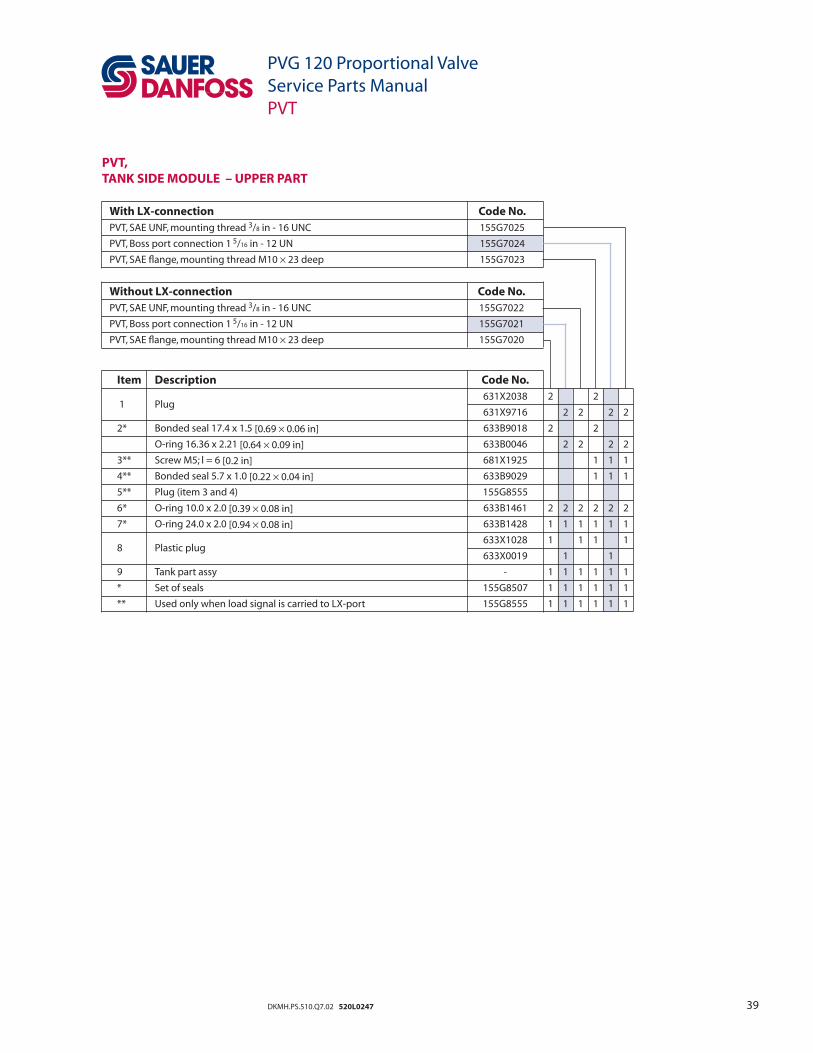
PVT,TANK SIDE MODULE – UPPER PART
With LX-connection Code No.PVT, SAE UNF, mounting thread 3/8 in - 16 UNC 155G7025
PVT, Boss port connection 1 5/16 in - 12 UN 155G7024
PVT, SAE fl ange, mounting thread M10 × 23 deep 155G7023
Item Description Code No.
1 Plug 631X2038 2 2
631X9716 2 2 2 2
2* Bonded seal 17.4 x 1.5 [0.69 × 0.06 in] 633B9018 2 2
O-ring 16.36 x 2.21 [0.64 × 0.09 in] 633B0046 2 2 2 2
3** Screw M5; l = 6 [0.2 in] 681X1925 1 1 1
4** Bonded seal 5.7 x 1.0 [0.22 × 0.04 in] 633B9029 1 1 1
5** Plug (item 3 and 4) 155G8555
6* O-ring 10.0 x 2.0 [0.39 × 0.08 in] 633B1461 2 2 2 2 2 2
7* O-ring 24.0 x 2.0 [0.94 × 0.08 in] 633B1428 1 1 1 1 1 1
8 Plastic plug
633X1028 1 1 1 1
633X0019 1 1
9 Tank part assy - 1 1 1 1 1 1
* Set of seals 155G8507 1 1 1 1 1 1
** Used only when load signal is carried to LX-port 155G8555 1 1 1 1 1 1
Without LX-connection Code No.PVT, SAE UNF, mounting thread 3/8 in - 16 UNC 155G7022
PVT, Boss port connection 1 5/16 in - 12 UN 155G7021
PVT, SAE fl ange, mounting thread M10 × 23 deep 155G7020

40 DKMH.PS.510.Q7.02 520L0247
PVT,TANK SIDE MODULE – LOWER PART
PVG 120 Proportional ValveService Parts ManualPVT

41DKMH.PS.510.Q7.02 520L0247
PVG 120 Proportional ValveService Parts ManualPVT
PVT,TANK SIDE MODULE – LOWER PART
Item Description Code No. 10 Screw M8 x 60 [0.31 × 2.36 in] 681X1146 3 3 3 3
11 Tank part assy - 1 1 1 1
12 Plug 155G7372 1 1
13* O-ring 17.5 x 2.4 [0.69 × 0.09 in] 633B1335 1 1
14* Filter 155B4056 1 1
15 Plug 155G7373 1 1
16* O-ring 19.3 x 1.5 [0.76 × 0.06 in] 633B1136 1 1
17 Stop 155G7376 1 1
18 Washer 10.0 x 16.0 x 0.5 [0.39 × 0.63 × 0.02 in] 684X2094 4 4
19 Spring 155G7375 1 1
20 Spool 155G7374 1 1
21 Plug 155L1373 1 1
22* O-ring 16.0 x 1.5 [0.63 × 0.06 in] 633B1813 1 1
23 Stop 155G7382 1 1
24 Washer 7.4 x 11.5 x 1.0 [0.29 × 0.45 × 0.04 in] 684X2547 2 2
25 Spring 155G7381 1 1
26 Ball 689X1040 1 1
* Set of seals 155G8524 1 1
Kit for hydraulic activation 155G7041 1 1
UNC Code No.PVT with pilot supply for PVE 155G7042
PVT without pilot supply for PVE 155G7062
BSP.F. thread Code No.PVT with pilot supply for PVE 155G7040
PVT without pilot supply for PVE 155G7060

42 DKMH.PS.510.Q7.02 520L0247
PVGI,INTERFACE, PVG 120 AND PVG 32
PVG 120 Proportional ValveService Parts ManualPVGI
43DKMH.PS.510.Q7.02 520L0247
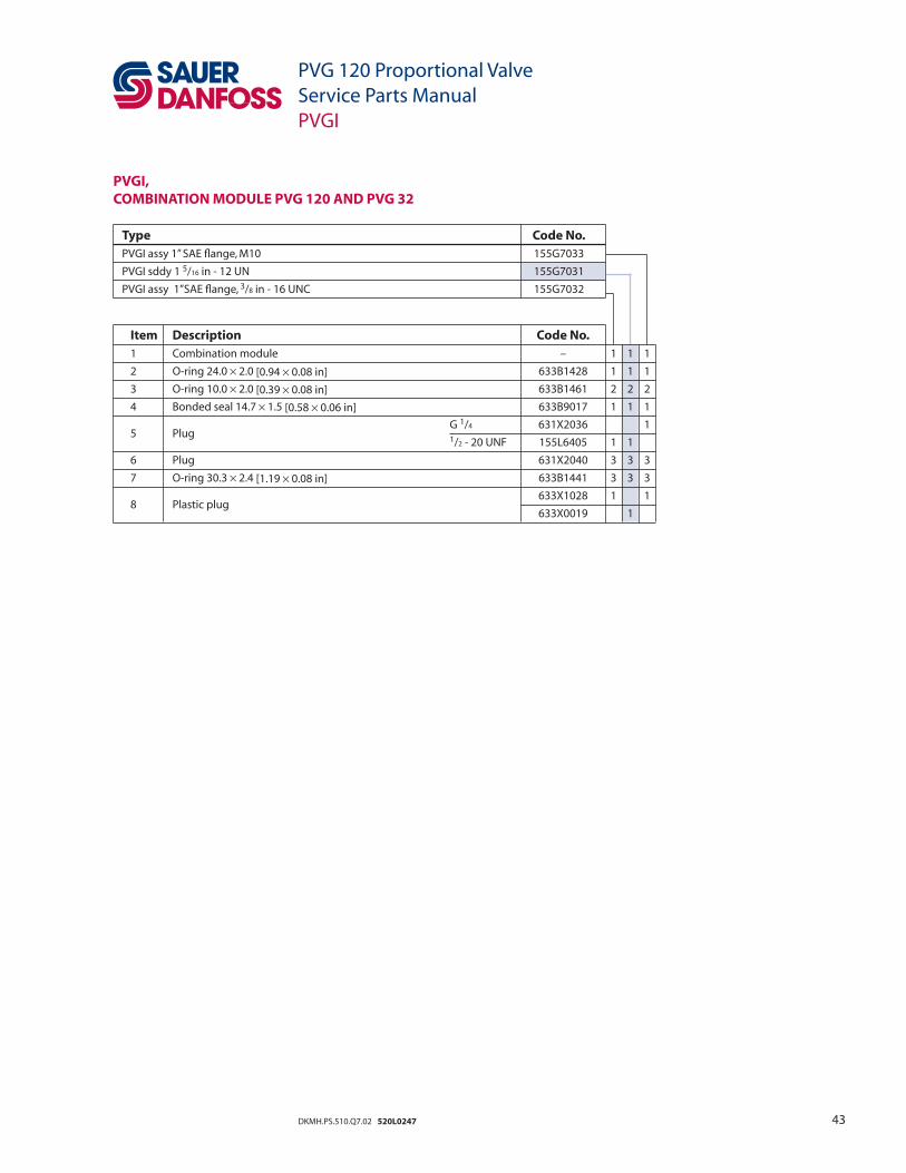
PVGI,COMBINATION MODULE PVG 120 AND PVG 32
PVG 120 Proportional ValveService Parts ManualPVGI
Type Code No.PVGI assy 1” SAE fl ange, M10 155G7033
PVGI sddy 1 5/16 in - 12 UN 155G7031
PVGI assy 1”SAE fl ange, 3/8 in - 16 UNC 155G7032
Item Description Code No. 1 Combination module – 1 1 1
2 O-ring 24.0 × 2.0 [0.94 × 0.08 in] 633B1428 1 1 1
3 O-ring 10.0 × 2.0 [0.39 × 0.08 in] 633B1461 2 2 2
4 Bonded seal 14.7 × 1.5 [0.58 × 0.06 in] 633B9017 1 1 1
5 Plug
G 1/4 631X2036 1
1/2 - 20 UNF 155L6405 1 1
6 Plug 631X2040 3 3 3
7 O-ring 30.3 × 2.4 [1.19 × 0.08 in] 633B1441 3 3 3
8 Plastic plug
633X1028 1 1
633X0019 1

44 DKMH.PS.510.Q7.02 520L0247
PVAS,ASSEMBLY KIT
PVGI,ASSEMBLY KIT
PVG 120 Proportional ValveService Parts ManualPVAS and PVGI
45DKMH.PS.510.Q7.02 520L0247
PVG 120 Proportional ValveService Parts ManualPVGI and PVAS
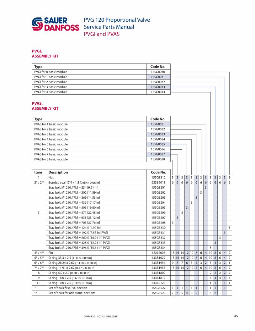
Type Code No.PVGI for 0 basic module 155G8040
PVGI for 1 basic module 155G8041
PVGI for 2 basic module 155G8042
PVGI for 3 basic module 155G8043
PVGI for 4 basic module 155G8044
Item Description Code No. 1 Nut 155G8312 3 3 3 3 3 3 3 3 3 3 3 3 3
2* / 2** Bonded seal 17.4 x 1.5 [0.69 × 0.06 in] 633B9018 6 6 6 6 6 6 6 6 6 6 6 6 6
Stay bolt M12 [0.47]; l = 234 [9.21 in] 155G8201 3
Stay bolt M12 [0.47]; l = 302 [11.89 in] 155G8202 3
Stay bolt M12 [0.47]; l = 369 [14.53 in] 155G8203 3
Stay bolt M12 [0.47]; l = 436 [17.17 in] 155G8204 3
Stay bolt M12 [0.47]; l = 503 [19.80 in] 155G8205 3
3 Stay bolt M12 [0.47]; l = 571 [22.48 in] 155G8206 3
Stay bolt M12 [0.47]; l = 638 [25.12 in] 155G8207 3
Stay bolt M12 [0.47]; l = 705 [27.76 in] 155G8208 3
Stay bolt M12 [0.47]; l = 124.5 [4.90 in] 155G8330 3
Stay bolt M12 [0.47]; l = 192.5 [7.58 in] PVGI 155G8331 3
Stay bolt M12 [0.47]; l = 260.5 [10.24 in] PVGI 155G8332 3
Stay bolt M12 [0.47]; l = 328.5 [12.93 in] PVGI 155G8333 3
Stay bolt M12 [0.47]; l = 396.5 [15.61 in] PVGI 155G8334 3
4* / 4** Pin 682L2006 18 16 14 12 10 8 6 4 10 8 6 4 2
5* / 5** O-ring 33.3 x 2.4 [1.31 × 0.09 in] 633B1029 18 16 14 12 10 8 6 4 10 8 6 4 2
6* / 6** O-ring 28.24 x 2.62 [1.118 × 0.10 in] 633B1956 9 8 7 6 5 4 3 2 5 4 3 2 1
7* / 7** O-ring 11.91 x 2.62 [0.47 × 0.10 in] 633B1955 18 16 14 12 10 8 6 4 10 8 6 4 2
8 O-ring 5.0 x 2.0 [0.20 × 0.08 in] 633B1809 2 2 2 2 2
9 O-ring 16.0 x 2.5 [0.63 × 0.10 in] 633B1817 4 4 4 4 4
11 O-ring 10.0 x 2.5 [0.39 × 0.10 in] 633B0120 1 1 1 1 1
* Set of seals fi rst PVG section 155G8522 1 1 1 1 1 1 1 1 1 1 1 1
** Set of seals for additionel sections 155G8523 7 6 5 4 3 2 1 3 2 1
PVGI,ASSEMBLY KIT
Type Code No.PVAS for 1 basic module 155G8031
PVAS for 2 basic module 155G8032
PVAS for 3 basic module 155G8033
PVAS for 4 basic module 155G8034
PVAS for 5 basic module 155G8035
PVAS for 6 basic module 155G8036
PVAS for 7 basic module 155G8037
PVAS for 8 basic module 155G8038
PVAS,ASSEMBLY KIT

46 DKMH.PS.510.Q7.02 520L0247
PVG 120 Proportional ValveService Parts ManualSet of seals
SET OF SEALS FOR
Type Code No.
PVP 155G8501PVB / PVB additional module 155G8502PVPH 155G8526PVPE 155G8527PVLP / PVLA 155G8525PVM 155G8518PVEH / PVEO 155G8519PVH / PVMD 155G8505PVT, Upper part 155G8507PVT (with pilot supply), Lower part 155G8524PVAS for fi rst PVG section 155G8522PVAS for additional sections 155G8523
Item Description Code No. 1 O-ring 8.3 x 2.4 [0.33 × 0.09 in] 633B0011 1 2 O-ring 20.35 x 1.78 [0.80 × 0.07 in] 633B0015 1 3 O-ring 16.36 x 2.21 [0.64 × 0.09 in] 633B0046 2 1 4 O-ring 29.82 x 2.62 [1.17 × 0.10 in] 633B0062 1 5 O-ring 26.7 x 1.78 [1.05 × 0.07 in] 633B0071 1 6 O-ring 27.0 x 2.0 [1.06 × 0.08 in] 633B0407 1 1 7 O-ring 6.3 x 2.4 [0.25 × 0.09 in] 633B1004 2 8 O-ring 42.0 x 2.0 [1.65 × 0.08 in] 633B1005 1 9 O-ring 33.3 x 2.4 [1.37 × 0.09 in] 633B1029 2 4 1 10 O-ring 15.0 x 2.0 [1.59 × 0.08 in] 633B1030 1 11 O-ring 8.0 x 2.0 [0.31 × 0.08 in] 633B1056 1 12 O-ring 19.3 x 2.4 [0.76 × 0.09 in] 633B1136 1
13 O-ring 8.0 x 2.0 [0.31 × 0.08 in] 633B1148 1 14 O-ring 10.0 x 2.0 [0.39 × 0.08 in] 633B1267 2 15 O-ring 17.5 x 2.4 [0.69 × 0.09 in] 633B1335 1 16 O-ring 24.0 x 2.0 [0.94 × 0.08 in] 633B1428 1 17 O-ring 25.3 x 2.4 [1.00 × 0.09 in] 633B1440 1 1 18 O-ring 30.3 x 2.4 [1.19 × 0.09 in] 633B1441 1 2 1 19 O-ring 6.0 x 2.0 [0.24 × 0.08 in] 633B1460 4 1 20 O-ring 10.0 x 2.0 [0.39 × 0.08 in] 633B1461 2 21 O-ring 13.3 x 2.4 [0.52 × 0.09 in] 633B1462 1 1 22 O-ring 20.3 x 2.4 [0.78 × 0.09 in] 633B1521 1 23 O-ring 16.0 x 1.5 [0.63 × 0.06 in] 633B1813 1 24 O-ring 10.52 x 1.83 [0.41 × 0.07 in] 633B1834 1 25 O-ring 11.91 x 2.62 [0.47 × 0.10 in] 633B1955 2 4 26 O-ring 28.24 x 2.62 [1.11 × 0.10 in] 633B1956 1 2 27 Profi le O-ring 13.3 x 2.4 [0.52 × 0.09 in] 155L3430 1 28 Washer 7.0 x 14.0 x 1.5 [0.28 × 0.55 × 0.06 in] 684X2367 1 1 29 Washer 16.2 x 19.9 x 1.5 [0.64 × 0.78 × 0.08 in] 684X2565 1 1 30 Bonded seal 10.35 x 2.0 [0.41 × 0.08 in] 633B9016 1 31 Bonded seal 14.7 x 1.5 [0.58 × 0.06 in] 633B9017 1 32 Bonded seal 17.4 x 1.5 [0.69 × 0.06 in] 633B9018 6 6 2 1 33 Bonded seal 5.7 x 1.0 [0.22 × 0.04 in] 633B9029 1 34 Back-up ring 633B0014 1 35 Back-up ring 633B0016 1 36 Back-up ring 633B0068 1 37 Back-up ring 155G2316 1 1 38 Filter 155G4710 1 39 Filter 155B4056 1 40 Seal nut 681X8270 2 41 Pin 682L2006 2 4

47DKMH.PS.510.Q7.02 520L0247
PVG 120 Proportional ValveService Parts ManualNotes
NOTES
Sauer-Danfoss Hydraulic Power Systems– Market Leaders Worldwide
Sauer-Danfoss is a comprehensive supplier providing complete systems to the global mobile market.
Sauer-Danfoss serves markets such as agriculture, construction, road building, material handling, municipal, forestry, turf care, and many others.
We offer our customers optimum solutions for their needs and develop new products and systems in close cooperation and partner ship with them.
Sauer-Danfoss specializes in integrating a full range of system components to provide vehicle designers with the most advanced total system design.
Sauer-Danfoss provides comprehensive worldwide service for its products through an extensive network of Authorized Service Centers strategically located in all parts of the world.
Sauer-Danfoss (US) Company2800 East 13th StreetAmes, IA 50010, USAPhone: +1 515 239-6000, Fax: +1 515 239-6618
Sauer-Danfoss (Neumünster) GmbH & Co. OHGPostfach 2460, D-24531 NeumünsterKrokamp 35, D-24539 Neumünster, GermanyPhone: +49 4321 871-0, Fax: +49 4321 871-122
Sauer-Danfoss (Nordborg) A/SDK-6430 Nordborg, DenmarkPhone: +45 7488 4444, Fax: +45 7488 4400
www.sauer-danfoss.com
OUR PRODUCTS
Hydrostatic transmissions
Hydraulic power steering
Electric power steering
Closed and open circuit axial piston pumps and motors
Gear pumps and motors
Bent axis motors
Radial piston motors
Orbital motors
Transit mixer drives
Planetary compact gears
Proportional valves
Directional spool valves
Cartridge valves
Hydraulic integrated circuits
Hydrostatic transaxles
Integrated systems
Fan drive systems
Electrohydraulic controls
Digital electronics and software
Battery powered inverter
Sensors
DKMH.PS.510.Q7.02 520L0247
Top Related