


Languages
Pages
Legal


doc.: IEEE 802.15-16-0007-02-007a January 2016
Submission Submission
Project: IEEE P802.15 Working Group for Wireless Personal Area Networks (WPANs)
Submission Title: Proposal for OWC Using Color Space Modulation
Date Submitted: Jan. 16, 2016
Source: Soo-Young Chang
Company: SYCA
Address:
Voice: 530 574 2741 FAX: E-Mail: [email protected]
Re: CFP of 15.7r1
Abstract: Proposal for OWC for low rate and high rate communications
Purpose: to submit a proposal for 802.15.7r1
Notice: This document has been prepared to assist the IEEE P802.15. It is offered as a basis for discus
sion and is not binding on the contributing individual(s) or organization(s). The material in this document
is subject to change in form and content after further study. The contributor(s) reserve(s) the right to add,
amend or withdraw material contained herein.
Release: The contributor acknowledges and accepts that this contribution becomes the property of IEEE
and may be made publicly available by P802.15.
Slide 1 Soo-Young Chang, SYCA

doc.: IEEE 802.15-16-0007-02-007a January 2016
Submission Submission Slide 2
COLOR SPACE MODULATION
PROPOSED
Soo-Young Chang, SYCA
Submission
doc.: IEEE 802.15-16-0007-02-007a January 2016
CONSIDERATIONS FOR MODULATION
• Need of brightness control or not
– Need superior brightness for optical wireless communications?
– It is more desirable for performance not to be affected by brightness control.
• Dependency of light source characteristics
– Is a modulation technique applied not dependent on technical characteristics of
LEDs or other light sources deployed?
• Not (or negligibly) affected by background noise or not
– Offsetting the impact of background light sources
– Stable data transmission should be achieved even if the background noise is strong.
– Offers high robustness to background light
• Data speed
– Low to high data rates to be realized: adaptive to the amount of information
delivered
– Adaptiveness to various data rates is important.
Soo-Young Chang, SYCA Slide 3

Submission
doc.: IEEE 802.15-16-0007-02-007a January 2016
MAJOR DISTINCTIONS BETWEEN OWC AND RADIO COMMUNICATION
OWC Radio comm.
Data delivery by manipulating and
measuring light, in terms of its perceived
brightness or color: light intensity, color,
etc.
The radiant power at each wavelength is
weighted by a luminosity function (a.k.a.
visual sensitivity function) that models
human brightness sensitivity.
Data delivery by manipulating
electromagnetic signals and detecting
parameters of the received signals or
measuring radiant energy: amplitude,
frequency, phase, etc.
A light signal which will be manipulated for
data delivery has a certain amount of
frequency (or wavelength) band before
modulation.
A carrier signal usually has a single
frequency component which is modulated
with data. Eventually the transmitted signal
has a certain amount of band after
modulation.
Soo-Young Chang, SYCA Slide 4

Submission
doc.: IEEE 802.15-16-0007-02-007a January 2016
FACTORS CONSIDERED FOR OWC MODULATION (1)
• Eye sensitivity
– To generate light with a color which is recognized by human eyes
– Human eyes have different sensitivity for each wavelength: luminocity functions
reflect human eyes’ sensitivity for various wavelengths.
– To determine colors recognized by human eyes after modulation
Soo-Young Chang, SYCA Slide 5
Wavelength in nm
Luminocity
value

Submission
doc.: IEEE 802.15-16-0007-02-007a January 2016
FACTORS CONSIDERED FOR OWC MODULATION (2)
• Spectral distribution of light emitting devices or light sources
– To realize colors to be recognized by human eyes
Soo-Young Chang, SYCA Slide 6
RGB LED spectral response An example
Submission
doc.: IEEE 802.15-16-0007-02-007a January 2016
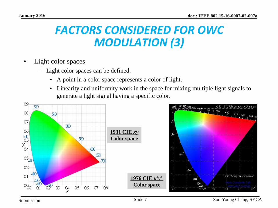
FACTORS CONSIDERED FOR OWC MODULATION (3)
• Light color spaces
– Light color spaces can be defined.
• A point in a color space represents a color of light.
• Linearity and uniformity work in the space for mixing multiple light signals to
generate a light signal having a specific color.
Soo-Young Chang, SYCA Slide 7
1976 CIE u'v'
Color space
1931 CIE xy
Color space

Submission
doc.: IEEE 802.15-16-0007-02-007a January 2016
FACTORS CONSIDERED FOR OWC MODULATION (4)
• Responsivities of photo detection devices
– Photo detection devices have different responsivities for each wavelength.
– At the receiver, post emphasis may be needed to compensate perceptual non-
uniformity.
Soo-Young Chang, SYCA Slide 8
Silicon PD spectral response An example

Submission
doc.: IEEE 802.15-16-0007-02-007a January 2016
FACTORS CONSIDERED FOR OWC MODULATION (5)
• Colors or comfortableness of light output from light emitting devices after
modulation
– After modulation, any of target colors should be able to be generated: to human
eyes.
– To mix multiple colors to generate any target color, a set of color coordination
coefficients (or intensities of light sources) should be considered.
• Communications should not degrade illumination efficiency.
– Compatible with dimming: no or minimum performance degradation due to
dimming
• Efficiency of constellation map in a light color space after considering all
factors
– The above factors should be considered to design a constellation map, given a
target color and the number of constellation points.
Soo-Young Chang, SYCA Slide 9

Submission
doc.: IEEE 802.15-16-0007-02-007a January 2016
BASIC CONCEPT: MULTI COORDINATES TO REPRESENT COLORS (1)
• In the modulation scheme suggested in this
document, two coordinates (x and y) for a
two dimensional light color space are
considered.
– x and y are designed to be orthogonal to each
other to be applied for the scheme:
• No correlation between these two.
• Any point in a space can be represented
by a unique pair of these values.
• A color is represented by a unique point
in a space, not by multiple points.
– Similar to QAM
• Determine points which maximize the
minimum distance among distances
between any two points.
• Equi-distance strategy is a possible way
to assign points. Soo-Young Chang, SYCA Slide 10

Submission
doc.: IEEE 802.15-16-0007-02-007a January 2016
BASIC CONCEPT: MULTI COORDINATES TO REPRESENT COLORS (2)
• A color can be generated by mixing lights from multiple light emitting devices
such as LEDs: multiple light sources based, not single light source based
– It is not necessary that light of a color can be generated by mixing light signals
from multiple light emitting devices with a unique set of light intensities of light
emitting devices.
– A multi dimensional space can be considered to represent colors.
A multi dimensional light color space can be used for color representation, but
generally it is not true that there is only one point to represent each color: multiple
points can be identified for a specific color.
Thus a light space should be well tailored not to have multiple points to represent a
color, but to represent a color with a unique point.
Soo-Young Chang, SYCA Slide 11

Submission
doc.: IEEE 802.15-16-0007-02-007a January 2016
MODULATION BLOCKS
Soo-Young Chang, SYCA Slide 12
• Transmitter
• Receiver
Serial-
to-parallel
convert
Data-to-
modulation
mapping
Light
emitting
device
driver
Light
emitting
device
Data stream from information source
Parallel-
to-serial
convert
Modulation
-to-data
demapping
Amplifier Photo
detector
Data stream to information sink
Light with a color recognized by human eyes
Submission
doc.: IEEE 802.15-16-0007-02-007a January 2016
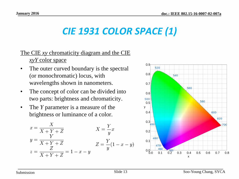
CIE 1931 COLOR SPACE (1)
The CIE xy chromaticity diagram and the CIE
xyY color space
• The outer curved boundary is the spectral
(or monochromatic) locus, with
wavelengths shown in nanometers.
• The concept of color can be divided into
two parts: brightness and chromaticity.
• The Y parameter is a measure of the
brightness or luminance of a color.
Soo-Young Chang, SYCA Slide 13

Submission
doc.: IEEE 802.15-16-0007-02-007a January 2016
CIE 1931 COLOR SPACE (2)
One important fact on CIE xyY color space
• The CIE 1960, CIE 1964, and CIE 1976 color spaces were developed, with the
goal of achieving perceptual uniformity (to have an equal distance in the
color space correspond to equal differences in color).
• Although they were a distinct improvement over the CIE 1931 system, they
were not completely free of distortion.
To utilize better perceptual uniformity, the CIE 1976 is more appropriate for a
color space for modulation schemes using the constellation planes in a light
color space including one suggested in this document. And also it has less area
that can not be covered by a triangle made with any three point colors.
Soo-Young Chang, SYCA Slide 14

Submission
doc.: IEEE 802.15-16-0007-02-007a January 2016
1976 CIE u’v’ COLOR SPACE
1976 CIE u’v’ (or CIE LUV)
Chromaticity Diagram (1)
• The advantage of the 1976 diagram is
that the distance between points is now
approximately proportional to the
perceived color difference, which is
definitely not true in the 1931 diagram.
attempted perceptual uniformity
additive mixtures of different colored
lights will fall on a line in CIE LUV's
uniform chromaticity diagram with a
condition that the mixtures are constant
in lightness.
Soo-Young Chang, SYCA Slide 15

Submission
doc.: IEEE 802.15-16-0007-02-007a January 2016
VARIOUS CONSTELLATION DIAGRAM TYPES
Soo-Young Chang, SYCA Slide 16

Submission
doc.: IEEE 802.15-16-0007-02-007a January 2016
BASIC CONCEPT (1)
• Transmission and reception (or detection) of light signals
– At the transmitter, multiple light sources (or light emitting devices) such as LEDs
with different spectral distributions are used for light emission.
– At the receiver, multiple photo detectors with different spectral responses are used
for light signal detection.
• Any color can be represented by a point in a multi-dimensional space
uniquely.
– Any color is represented by a point in an n dimensional space. It is because in
general light generated by each device can also be generated by mixing light
signals from other devices which have different spectral distributions.
Thus multi-dimensional space should be defined to represent a color with a point
uniquely in this space.
– A unique color for a point in a space can be generated by mixing light signals
emitted from n light emitting devices and be detected by processing light
signals detected by k photo detectors.
Soo-Young Chang, SYCA Slide 17
Submission
doc.: IEEE 802.15-16-0007-02-007a January 2016
BASIC CONCEPT (2)
Light Signal Delivery Model from Transmitter to Receiver
• Radiation at Transmitter
– Multiple light emitting devices emit light signals at transmitter. Each device has its
own spectral distribution, S(λ), which determines its emitted power by calculating
total power throughout the whole wavelength range.
– By using the color matching functions of a light space and by calculating stimulus
values –for two dimensional space, X, Y and Z values -of the light space, the color
of emitted light perceivable by human eyes can be determined.
– By using these values, a point of a light signal in a color space can be determined.
Soo-Young Chang, SYCA Slide 18
Submission
doc.: IEEE 802.15-16-0007-02-007a January 2016
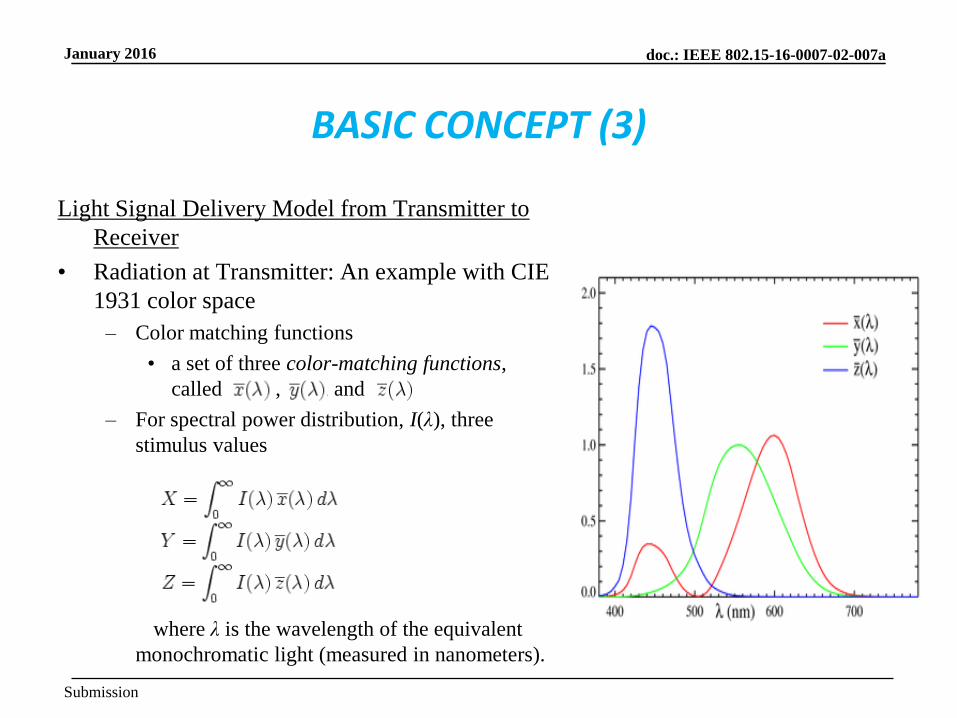
Light Signal Delivery Model from Transmitter to
Receiver
• Radiation at Transmitter: An example with CIE
1931 color space
– Color matching functions
• a set of three color-matching functions,
called , , and
– For spectral power distribution, I(λ), three
stimulus values
where λ is the wavelength of the equivalent
monochromatic light (measured in nanometers).
BASIC CONCEPT (3)
Submission
doc.: IEEE 802.15-16-0007-02-007a January 2016
BASIC CONCEPT (4)
Light Signal Delivery Model from Transmitter to Receiver
• Perception by Human Eyes
– To know how human eyes react to emitted light:
• An emitted light signal which has a spectral distribution, S(λ), is multiplied by
a standardized luminosity function - wavelength-weighted by the luminosity
function to correlate with human brightness perception. Then total power
perceived by human eyes can be determined.
• Detection at Receiver
– The emitted signal is delivered to the detector which is characterized by its
responsivity, its own spectral sensitivity, which determines the spectral
characteristics of the received light signal and total received power to determine a
color detected.
Soo-Young Chang, SYCA Slide 20

Submission
doc.: IEEE 802.15-16-0007-02-007a January 2016
BASIC CONCEPT (5)
Soo-Young Chang, SYCA
Intensity c1 Intensity c2
Intensity cn
Intensity c’1
Intensity c’2
Intensity c’k
n light emitting devices
k photo detectors
light
ctotal = c1+c2+…+cn
where ci = ∫si(λ)dλ
c’total = c’1+c’2+…+c’k
where c’i = ∫s’i(λ)dλ
transmitter receiver
Transmitted light power:
∑∫si(λ)dλ
Received light power:
∑ ∫s’i(λ)dλ
noise
interference + =
channel
Light Signal Delivery Model from Transmitter to Receiver Intensity
Slide 21
Submission
doc.: IEEE 802.15-16-0007-02-007a January 2016
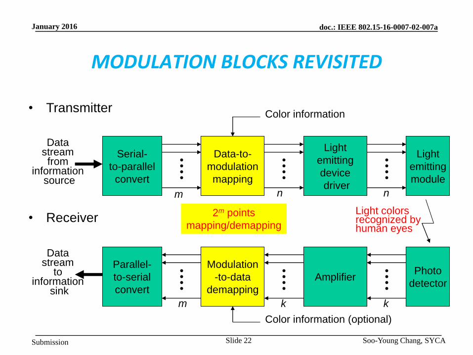
MODULATION BLOCKS REVISITED
Soo-Young Chang, SYCA
• Transmitter
• Receiver
Serial-
to-parallel
convert
Data-to-
modulation
mapping
Light
emitting
device
driver
Light
emitting
module
Data stream from
information source
Parallel-
to-serial
convert
Modulation
-to-data
demapping
Amplifier Photo
detector
Data stream
to information
sink
m n n
k k m
2m points
mapping/demapping
Color information
Light colors recognized by human eyes
Color information (optional)
Slide 22

Submission
doc.: IEEE 802.15-16-0007-02-007a January 2016
MODULATION MAPPING
Soo-Young Chang, SYCA
mapper
b1
b2
bm
c1
c2
cn
demapper
c’1 b’1
b’2
b’m
c’2
c’k
Data-to-modulation mapping (transmitter)
Modulation-to-data demapping (receiver)
Slide 23

Submission
doc.: IEEE 802.15-16-0007-02-007a January 2016
GENERATION OF CONSTELLATION (1)
• Assumptions
– Equi-probable data elements
– For duration of a fixed number of symbols,
color is not changed.
• Input
– Information data: m bits 2m symbol
elements 2m points
– Color information: (xc,yc)
• Output
– Constellation: (x,y)
• Two parameters considered to pick points in a
light space
– Colors perceptible by human eyes
– Equi-distance between two adjacent points
when points are detected by photo detectors
Soo-Young Chang, SYCA
x
y
Target color position
Displacement vector
(0,0)
Slide 24

Submission
doc.: IEEE 802.15-16-0007-02-007a January 2016
GENERATION OF CONSTELLATION (2)
• Maximum area of constellation is
determined by two factors:
– Point of a target color visible to
human eyes: this point becomes the
origin of constellation.
– Gamut formed by primary color
points which represent points of
light emitting devices used.
Maximum constellation area
determined
Soo-Young Chang, SYCA
Point of target color
Max area of constellation
Point of a light emitting device
Gamut formed by seven light emitting devices
Constellation area with radius rc
Slide 25
rc

Submission
doc.: IEEE 802.15-16-0007-02-007a January 2016
GENERATION OF CONSTELLATION (3)
Normalized constellation
Inside a unit circle centered at the original,
2m points are assigned so that the minimum
distance between any two points be
maximized.
Soo-Young Chang, SYCA
y
y
y
x
x
x
m=2
2m=4 points
m=3
2m=8 points
m=4
2m=16 points
Examples of constellation
Slide 26
Submission
doc.: IEEE 802.15-16-0007-02-007a January 2016
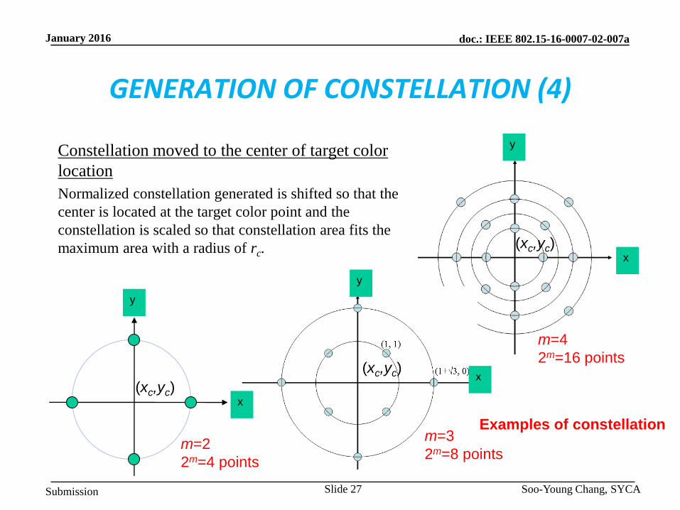
GENERATION OF CONSTELLATION (4)
Constellation moved to the center of target color
location
Normalized constellation generated is shifted so that the
center is located at the target color point and the
constellation is scaled so that constellation area fits the
maximum area with a radius of rc.
Soo-Young Chang, SYCA
y
y
x
m=4
2m=16 points
Examples of constellation
x
y
m=3
2m=8 points
x
m=2
2m=4 points
(xc,yc)
(xc,yc)
(xc,yc)
Slide 27
Submission
doc.: IEEE 802.15-16-0007-02-007a January 2016
CONSTELLATION TO (c1, c2, . . ., cn) MAPPING
• Assumption
– Perceptual uniformity or linearity of light emitting devices and photo detectors in
the light space
• Input/output
– Input: Constellation: (x,y)
– Output: (c1, c2, . . . , cn)
• Two cases for color properties of light emitting devices
1. Using (xi,yi) i=1, 2, .., n for all light emitting devices if (xi,yi) i=1, 2, .., n, is given
2. Using spectral distributions of light emitting devices if (xi,yi) i=1, 2, .., n, is not
given
Soo-Young Chang, SYCA Slide 28

Submission
doc.: IEEE 802.15-16-0007-02-007a January 2016
(c’1, c’2, . . ., c’k) TO CONSTELLATION DEMAPPING
• Assumption
– Uniformity or linearity of light emitting devices and photo detectors in the light
space
– The receiver has constellation information that the transmitter applies.
• Input/output
– Input: (c’1, c’2, . . . , c’k): light intensities measured by photo detectors: noise added
from channels to produce these coefficients
– Output: information point, (x’, y’), in a constellation most closely matching to a set
of light intensities, (c’1, c’2, . . . , c’k)
• Two cases for color detection properties of photo detectors
1. Using (x’i,y’i), i=1, 2, .., k, for all photo detectors if these values are given
2. Using spectral distributions of photo detectors if (x’i,y’i), i=1, 2, .., k, is not given
Soo-Young Chang, SYCA Slide 29
Submission
doc.: IEEE 802.15-16-0007-02-007a January 2016
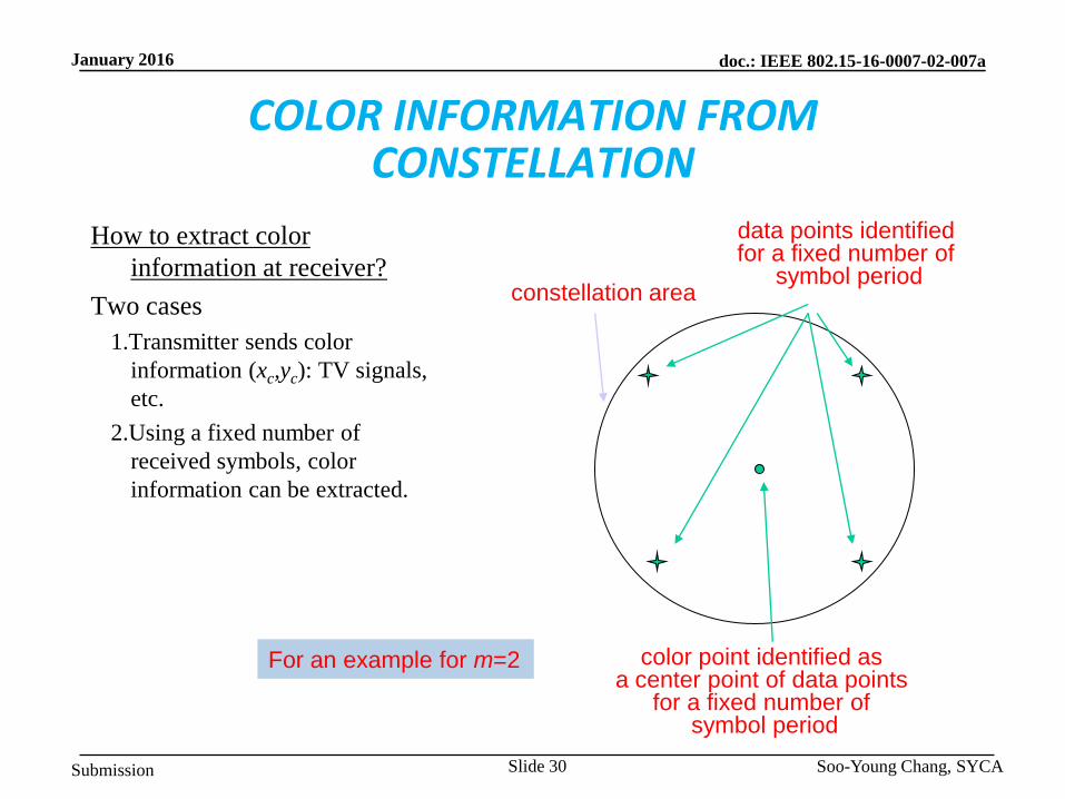
COLOR INFORMATION FROM CONSTELLATION
How to extract color
information at receiver?
Two cases
1.Transmitter sends color
information (xc,yc): TV signals,
etc.
2.Using a fixed number of
received symbols, color
information can be extracted.
Soo-Young Chang, SYCA
data points identified for a fixed number of
symbol period constellation area
color point identified as a center point of data points
for a fixed number of symbol period
For an example for m=2
Slide 30

Submission
doc.: IEEE 802.15-16-0007-02-007a January 2016
INFORMATION DATA FROM CONSTELLATION (1)
With an assumption that
• Gamut formed by photo detectors should include all area of gamut formed by
light emitting devices at transmitter. If not, some distortion is inevitable.
How to extract constellation scaling factor for a color at receiver?
How to get a constellation at receiver?
Some cases can be considered:
1.Periodically the transmitter broadcasts information on light emitting devices used.
2.Whenever color changes or periodically with a fixed interval, transmitter broadcasts
scaling factor information with color information.
3.Without any information listed above, the receiver can know color information
and constellation by examining points of a fixed number of previously received
symbols.
Soo-Young Chang, SYCA Slide 31

Submission
doc.: IEEE 802.15-16-0007-02-007a January 2016
INFORMATION DATA FROM CONSTELLATION (2)
Case that target color information
delivered from transmitter (Case 1)
Extraction of information data from
received signals
Soo-Young Chang, SYCA
Point of target color
Area of constellation Point of a
photo detector
Gamut formed by seven photo detectors
Slide 32

Submission
doc.: IEEE 802.15-16-0007-02-007a January 2016
INFORMATION DATA FROM CONSTELLATION (3)
Soo-Young Chang, SYCA Slide 33
i
i
i
i
i
i
i
i
i
i
c
yc
y
c
xc
x
'
''
'
'
''
'
Calculation of (x’, y’)
• Basic equations to calculate (x’, y’), position of a
received light in the light space
i
i
i
i
i
i
i iii
ii
i
i
i
i
i
i
i iii
ii
c
dys
c
ZYX
dysc
y
c
dxs
c
ZYX
dxsc
x
'
'
'
'''
''
'
'
'
'
'''
''
'
)()(
)()(
)()(
)()(
(c1’ c2’, .., ck’) is given. need to calculate x’ and y’.
For the case that
(xi’,yi’) i=1, 2, ..,
k is given
For the case that spe
ctral distributions of
all light emitting dev
ices are given,
since ci = Xi+Yi+Zi,

Submission
doc.: IEEE 802.15-16-0007-02-007a January 2016
WHY THIS MODULATION ? MOTIVATION TO CSM (1)
• Not affected by light intensity and intensity variation: not intensity modulation
– Only related to positions of signals in a light space
– Dimming control is not a problem to implement.
• Any colors can be generated, visible to human eyes: independent of colors
– Independent of color of light signal from each light source
– Any target color can be generated perceivable to human eyes
• Progressive modulation can be achieved without any serious burden
– Low to high data rates can be achieved with a common constellation (scheme)
corresponding to various applications
– By varying number of points in a constellation and symbol periods
• An example
– Lower data rate for remote controlling: 2-CSM, 1 symbol/4 symbol
periods 1/4 bit/symbol period
– Higher data rate for file transfer: 64-CSM, 1 symbol/1 period 6
bits/symbol period
Adaptive to various data rates and colors Soo-Young Chang, SYCA Slide 34
Submission
doc.: IEEE 802.15-16-0007-02-007a January 2016
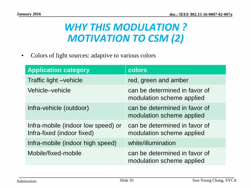
WHY THIS MODULATION ? MOTIVATION TO CSM (2)
• Colors of light sources: adaptive to various colors
Soo-Young Chang, SYCA
Application category colors
Traffic light –vehicle red, green and amber
Vehicle–vehicle can be determined in favor of
modulation scheme applied
Infra-vehicle (outdoor) can be determined in favor of
modulation scheme applied
Infra-mobile (indoor low speed) or
Infra-fixed (indoor fixed)
can be determined in favor of
modulation scheme applied
Infra-mobile (indoor high speed) white/illumination
Mobile/fixed-mobile can be determined in favor of
modulation scheme applied
Slide 35

Submission
doc.: IEEE 802.15-16-0007-02-007a January 2016
WHY THIS MODULATION ? MOTIVATION TO CSM (3)
• With peak available transmit power fixed,
– Use full power for data representation: more power can be used for transmission for
the case of confined peak power.
Higher average transmit power
Longer range
Lower BER
more desirable.
• Self identification of colors of light signals detected
– should not depend on the color transmitted
– should not depend on the intensity of transmitted signals
• Not intensity modulation, but constellation modulation in a color space: each
point (or symbol) represented by two coordinates in a color space
Soo-Young Chang, SYCA Slide 36

Submission
doc.: IEEE 802.15-16-0007-02-007a January 2016
WHY THIS MODULATION ? MOTIVATION TO CSM (4)
• Simple implementation
– At the transmitter
• Given x and y coordinates or spectral distributions of n light emitting devices
in a light space used for the light sources by manufacturers
• Only a look-up table applied for data to intensities mapping for 2m CSM
– At the receiver
• Given x and y coordinates or spectral responses of k photo detection devices
in a light space used for the light signal detection by manufacturers
• A simple formula applied for intensities to data demapping for 2m CSM
Soo-Young Chang, SYCA Slide 37

Submission
doc.: IEEE 802.15-16-0007-02-007a January 2016
SIMULATION RESULTS USING CIRS GIVEN (1)
• Scenario 1 a) Open Office D1~24
Soo-Young Chang, SYCA Slide 38

Submission
doc.: IEEE 802.15-16-0007-02-007a January 2016
SIMULATION RESULTS USING CIRS GIVEN (2)
Soo-Young Chang, SYCA Slide 39

Submission
doc.: IEEE 802.15-16-0007-02-007a January 2016
SIMULATION RESULTS USING CIRS GIVEN (3)
Soo-Young Chang, SYCA Slide 40
0.000
0.100
0.200
0.300
0.400
0.500
0.600
0.700
0.800
0.900
1.000
D1 D2 D3 D4 D5 D6 D7 D8 D9 D10 D11 D12 D13 D14 D15 D16 D17 D18 D19 D20 D21 D22 D23 D24
SE
R
On/Off Intensity CSM

Submission
doc.: IEEE 802.15-16-0007-02-007a January 2016
SER COMPARISON ON COLOR MODELS
constellation diagram
Symbol decision method in receiver.
1. x, y decision in CIE1931
2. H, S decision in HSV model
3. R, G, B decision in RGB model
SER graph (TC1)
Slide 41 Soo-Young Chang, SYCA

Submission
doc.: IEEE 802.15-16-0007-02-007a January 2016
DATA RATES ACHIEVED
…
…
N
N
Encoding
Using m(=2n) symbols
n [bits/symbol]
LED Array size
N x N = N2 [symbol]
Camera frame rate
F [fps]
Data rate = n x N2 x F [bps]
Slide 42 Soo-Young Chang, SYCA

Submission
doc.: IEEE 802.15-16-0007-02-007a January 2016
COLOR INDEPENDENT VISUAL-MIMO (1)
Soo-Young Chang, SYCA
Color independent Visual-MIMO tranceiving procedure
Slide 43

Submission
doc.: IEEE 802.15-16-0007-02-007a January 2016
COLOR INDEPENDENT VISUAL-MIMO (2)
Soo-Young Chang, SYCA
Visual-MIMO System
LEA (Light Emitting Array)
1. LED
2. Display screen
Camera or PD
1. Smart phone
2. Vehicle
3. CCTV
Slide 44

Submission
doc.: IEEE 802.15-16-0007-02-007a January 2016
CONCLUSIONS
• Color space modulation scheme proposed has many advantages
– Independent of brightness control
• Not to be affected by brightness control.
– Dependency of light source (such as LEDs) characteristics
• Modulation technique applied is not directly dependent on technical
characteristics of LEDs or other light sources deployed.
– Not (or negligibly) affected by background noise
– Adaptiveness to various data rates
– Simple implementation
• This modulation scheme proposed has better performance than other intensity
modulations.
– Need more simulation results .
• This modulation scheme can be applied to High Rate OWC areas while other
low rate OWC areas.
Soo-Young Chang, SYCA Slide 45
Top Related