


Languages
Pages
Legal


Approvals and Certificates
Engineering for Industrial Automation
UL RecognizedATEX - Directive 94/9
II2G / Ex d IIB T3 Gb II2D / Ex tb IIIC T3 Db
N C COCP 0034
Segurança Associationcanadienne de normalisationCanadianStandars Association
General Catalog / 3bProduct Data and Specifications
Solenoid Valves
ISO 9001
Certified

Jefferson Lupatech is a group of companies that serve 3 business lines - Energy Products, Flow Control and Metallurgy. JEFFERSON SUDAMERICANA S.A. is part of the Flow Control group.
The company has been manufacturing solenoid valves, magnetic level switches and other industrial automation equipment for over 45 years. Since its birth it has dedicated itself to serve and respond to the needs of its customers, continuously incorporating new features. Constantly perfecting its products, using state of the art machinery, it is now a redesigned organization to comply to the ISO 9001 standards, with a product engineering and market -designed orientation controlled by engineers and technical specialists that check all the manufacturing stages that have made JEFFERSON, not only a pioneer in Latin Argentina, but a leader in the control of fluids.Currently, its catalog of standard products includes over 3.000 models between solenoid valves and magnetic level switches which satisfy different needs and industrial requirements to control the most diverse liquids and gases such as water, air, steam, oils, refrigerants, oxygen, liquid nitrogen (-200°C), corrosive fluids and many others. Its principal customers cover a wide spectre of world-wide industry: petroleum; engineering; laboratories; construction; food and beverage; heating; automobiles; metallurgical; textile; chemical & petrochemical; etc.JEFFERSON's head offices and principal manufacturing plant is situated in Buenos Aires, Argentina only twenty minutes away
from Ezeiza International Airport and the banking district in down-town. Equipped with the latest designed CNC machinery all assisted by computers it produces high quality products for its local and export markets.Its products have international recognition as attested by the approvals of UNDERWRITERS LABORATORIES (UL) in the USA, CANADIAN STANDARDS ASSOCIATION (CSA) in Canada, amongst other, which has permitted Jefferson to introduce its products range -in direct competition with other market leaders- in more than 22 countries covering the Five Continents in such competitive markets as the USA, Canada, Mexico, Brazil, Autralia, Japan, Taiwan, Greece and recently, in closed countries such as Japan, Taiwan and Singapore, with special models. Jefferson's international insertion is reflected with the establishment in Brazil through JEFFERSON SOLENOIDBRAS LTDA., in Mexico through VALJEFF S.A. de C.V., in the U.S.A. throughJEFFERSON SOLENOID VALVES U.S.A. INC. with seat in Miami and sales offices in New York, from which they are taken care of U.S.A. market and Canada. In addition a network of distributors in the rest of the countries of America and the rest of the world, fulfill the objective to cover with sales and services in all the orb.JEFFERSON is continuously visiting sites, assisting industrial projects to understand the markets' needs and offer solutions -which may require new designs- thinking and planning for the future
JeffersonA Leader in Industrial Automation
is a group of companies that serve 3 business lines:Energy Products, Flow Control and Metallurgy. Jefferson is part of the Flow Control group.

General Catalog / 3bProduct Data and Specifi cations
Solenoid Valves
ArgentinaHeadquarters and PlantJefferson Sudamericana S.A.Avda. F. Fernández de la Cruz 2016 C1437GYZ - Buenos Aires - Argentinawww.jefferson.com.ar Departamento de comercio Interior:Tel.: (5411) 4909-5300Fax: (5411) 4909-5343 / [email protected] de comercio Exterior:Tel.: (5411) 4909-5301 / 4909-5302Fax: (5411) 4909-5390 / [email protected]
U.S.A.Jefferson Solenoid Valves U.S.A. Inc.20225 NE 15TH CTMiami, FL 33179 - USATel. 305-249-8120 / Fax: 305-249-8121Toll Free: 1-866-42-VALVE (82583)[email protected]
MéxicoValjeff, S.A. de C.V.Pino #18 Col. FloridaDel. Alvarado ObregónC.P. 01030 México, DFTels.(52 55) 5662.43.85 / 5663.03.16 (52 55) [email protected]
BrazilJefferson Solenoidbras Ltda.Rua Edgard Gerson Barbosa, 266/270 Vila Daisy Sâo Bernardo do Campo - SP - Brasil Cep: 09732-520Tel.: (5511) 4336-7033Fax: (5511) [email protected]

Index Edition: 48IU-05-0213-3000
D - 3, 4 and 5 Way Solenoid Valves for Pneumatic and Hydraulic Use. 3/2 ways. N.closed and N.open or universal.
Direct acting.3/2 ways. N.closed and N.open. Pilot operated.4/3 ways. Closed center. Pilot operated.5/2 ways. Monostable and bistable.Pilot operated.3/2 ways. N. closed, N. open or bistable. Pilot operated.3/2 ways. N. closed, N. open or universal. Direct acting.5/2 ways. Direct NAMUR mount. Pilot operated.
1323 Series
1325 Series
1339 Series
1350 Series
1351 Series
1365 Series
1375 Series
D-2 / D-3D-4 / D-5D-6 / D-7D-8 / D-9
D-10 / D-11
D-12 / D-13D-14
D-1
C - 2 Way Solenoid Valves for Combustion Use. Combustion
1312 Series
2012 Series
1330 Series
2030 Series
1332 Series
1356 Series
1388 Series
2088 Series
V171 Series
Solenoid valves. For liquid fuel and combustible gases.2 way solenoid valves. For fuel oil.2 way solenoid valves. For fuel oil.2 way valves. For fuel gas and other gases.2 way valves. For fuel gas and other gases.Free handle manual reset safety valve.2 way solenoid valves for fuel oil, gas-oil and mixtures thereof.Solenoid valves with slow opening and quick shutoff.Solenoid valves with slow opening and quick shutoff.Thermoelectric safety valves.
C-2 / C-3 C-4 / C-5 C-6 / C-7C-8 / C-9C-8 / C-9
C-10 / C-11C-10 / C-11C-12 / C-13
C-14 / C-15
C-16 / C-17 / C-18 / C-19
C-20 / C-21 / C-22C-23 / C-24
C-1
1314 Series
1327 Series
1335 Series
1342 Series
1390 Series
1393 Series
2026 Series
2036 Series
2036V Series
1359 Series
Normally closed. Pilot operated.Normally closed and Normally open. Direct acting.Normally closed and Normally open. Direct acting or pilot operated.Normally closed and Normally open. Pilot operated.Normally closed and Normally open. Pilot operated.Normally closedand Normally open. Direct acting.Normally closed Microvalve. Direct acting.Normally closed. Pilot operated.Solenoid valves. General purpose.“Y” strainer for general purpose.
B-2 / B-3
B-4 / B-5B-6 / B-7
B-8 / B-9
B-10 / B-11
B-12 / B-13B-14 / B-15B-16 / B-17 B-16 / B-17
B-18
B - 2 Way Solenoid Valves. for General Purpose B-1
A-2A-3
A-4 / A-5A-6 / A-7 A-8 / A-9
A-10 / A-11A-12 / A-13
A-14 / A-15 / A-16
Pages
Introduction.Application: uses.Necessary data for selecting and / or purchasing solenoid valves.Tables and formulaFlow charts.Coils and housings.Selection guide.
A - Solenoid valves. Engineering Information
A-1
1310 Series
1311 Series
1360 Series
1369 Series
2073 Series
1372 Series
2094 Series
1370 Series
1398 Series
“UC” Series
“CP” Series
Pneumatically operated globe valves.Pneumatically operated diaphragm valves.Solenoid valves for corrosive fl uids.Manual reset device for solenoid valvesSolenoid valves for dust collector systems.Pneumatic operator.Solenoid valves for CNG (VNG).Pulse operated solenoid unit.Digital condensation removal timer.Solenoid valves for cryogenic fl uids. Power control.
E-2 / E-3E-4 / E-5E-6 / E-7E-8 / E-9
E-10E-11
E-12 / E-13E-14 E-15
E-16 / E-17E-18
E - Valves and Devices for Special Service
Pages
E-1
F - Technical information
F-2 / F-3F-4 F-5
F-6 / F-7 / F-8
Corrosive fl uids table.Recommendations for installation.Problems and solutions.Repair Kits.
F-1
New products NEW SOLENOID VALVE MODELS
• Intrinsically Safe. • Low Power. • For Vacuum Systems. • Slow-Opening for Gas - 1/2” & 3/4”.• Hydraulic, Water Hammer-Proof. • ATEX Explosion-Proof Coils. • For CNG Compressors. • For CNG Automotive Use.
To request a technical bulletin for models that are not included in this catalog, please contact JEFFERSON at:
H - Equivalences
Unit Conversion Table H-1
3/2 ways. Direct NAMUR mount. Direct acting or pilot operated. 5/2 ways. Monostable and bistable.Pilot operated.3/2 ways. N. closed, N. open or bistable. Pilot operated.3/2 and 5/2 ways. Direct NAMUR mount. Pilot operated.Additional information5/2 ways. Pilot operated.
1387 Series
2050 Series
2051 Series
2095 Series
SI Series
2024 Series
D-15D-16 / D-17
D-18 / D-19
D-20 / D-21D-22 / D-23
D-24

A-1
A-4 / A-5
A-3
A-2
Pages
Introduction.
Application: uses.
Necessary data for selecting and / or purchasing solenoid valves.
Tables and formulas.
Flow charts.
Coils and housings.
Selection guide.
A-6 / A-7 / A-8 / A-9
A-10 / A-11
A-12 / A-13
A-14 / A-15 / A-16
Solenoid valvesEngineering Information
SolenoidValves
A-2
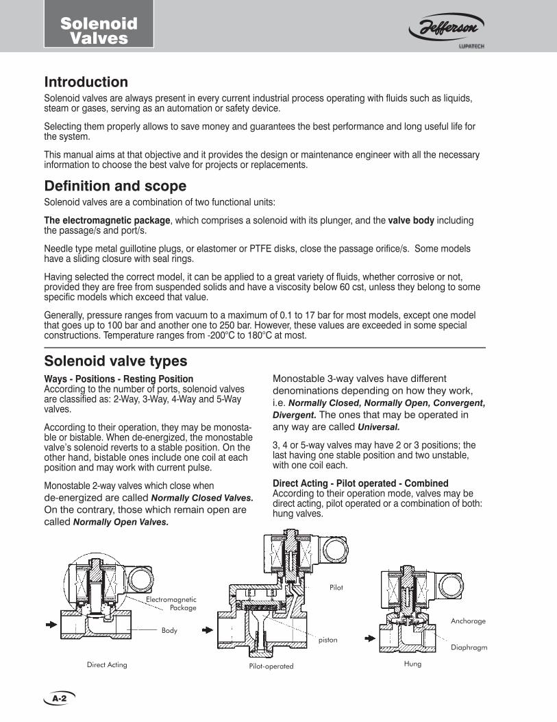
Monostable 3-way valves have different denominations depending on how they work, i.e. Normally Closed, Normally Open, Convergent, Divergent. The ones that may be operated in any way are called Universal.
3, 4 or 5-way valves may have 2 or 3 positions; the last having one stable position and two unstable, with one coil each.
Direct Acting - Pilot operated - CombinedAccording to their operation mode, valves may be direct acting, pilot operated or a combination of both: hung valves.
Solenoid valve typesWays - Positions - Resting PositionAccording to the number of ports, solenoid valves are classifi ed as: 2-Way, 3-Way, 4-Way and 5-Way valves.
According to their operation, they may be monosta-ble or bistable. When de-energized, the monostable valve’s solenoid reverts to a stable position. On the other hand, bistable ones include one coil at each position and may work with current pulse.
Monostable 2-way valves which close when de-energized are called Normally Closed Valves.On the contrary, those which remain open are called Normally Open Valves.
IntroductionSolenoid valves are always present in every current industrial process operating with fl uids such as liquids, steam or gases, serving as an automation or safety device.
Selecting them properly allows to save money and guarantees the best performance and long useful life for the system.
This manual aims at that objective and it provides the design or maintenance engineer with all the necessary information to choose the best valve for projects or replacements.
Defi nition and scopeSolenoid valves are a combination of two functional units:
The electromagnetic package, which comprises a solenoid with its plunger, and the valve body including the passage/s and port/s.
Needle type metal guillotine plugs, or elastomer or PTFE disks, close the passage orifi ce/s. Some models have a sliding closure with seal rings.
Having selected the correct model, it can be applied to a great variety of fl uids, whether corrosive or not, provided they are free from suspended solids and have a viscosity below 60 cst, unless they belong to some specifi c models which exceed that value.
Generally, pressure ranges from vacuum to a maximum of 0.1 to 17 bar for most models, except one model that goes up to 100 bar and another one to 250 bar. However, these values are exceeded in some special constructions. Temperature ranges from -200°C to 180°C at most.
Hung
Diaphragm
Anchorage
Pilot-operated
piston
Pilot
Direct Acting
Body
ElectromagneticPackage

SolenoidValves
A-3
These families are:General purpose valvesThese are used in a great variety of systems and different industrial areas that handle water, air, steam, light oils, neutral gases and cryogenic fl uids, from vacuum to high pressure and high temperature.Some application examples are: automatic petrol and beverage pumps, sector-programmed park irrigation, sown land, dancing water fountains, oxyacetylene welding equipments, electric welding under inert atmosphere, fi re-extinguisher systems, liquid or gas dosing, liquid level regulation, packing machines, water treatment systems, pneumatic expellers, car washing machines, building exterior cleaning machines, nickel-plating process, galvanization, coffee machines, car systems against theft or gas selection systems, air heating systems, hot water, steam, hot oils, laboratory or industrial cryogenic systems, low and high vacuum regulation, ink drying systems, etc.Refrigeration ValvesThese are used for refrigerating fl uids in their different aggregation degrees. So the connections and construction materials are specifi c for commercial or industrial refrigeration systems. You shall fi nd information about this kind of valves in the Refrigeration Manual.Fuel ValvesThese are used for automation, for the security of combustion equipments for boilers, furnaces, etc., and for the oil and petrochemical industries.
Directional Valves for Pneumatic and / or Hydraulic SystemsThese are 3, 4 and 5-way valves used to direct the fl ow needed to operate single or double acting cylinders.They are also used when two fl uids are to enter the same circuit (convergence), or one fl uid into two circuits (divergence).Valves for corrosive or contaminated productsThese valves use plastic materials which are compatible with the fl uid, isolating the internal materials that are not compatible, such as the fi xed core and the plunger, so as to avoid corrosion or fl uid contamination.Pneumatically and / or Hydraulically Operated ValvesThese are used when there are no solenoid valves available due to size, pressure, working temperature, type of fl uid or special service conditions (explosive areas, corrosive fl uids, etc.).Dust collector ValvesDue to their special design, response time and fl ow, these are used for shaking dust collector sleeves by means of periodical pressurized air pulses.Manual Reset ValvesThese are used in shut-off security systems for temperature limit, pressure, lack of fl ame, level, etc. They are widely used in the oil industry and combustion.
Manual ResetMany safety systems require manual reset solenoid valves.
Automatic operation (due to the absence or presence of electric signal) takes place only to adopt one position, which may be open or closed, but it does not return to the previous one unless the operator in charge manually activates a lever ad hoc. 1332 and 1369 Series are examples of these devices.
Valves operated with air, water or any other auxiliary fl uid.These are not solenoid valves, though they may be considered as such when a pilot solenoid valve integrated to the equipment carries the auxiliary fl uid signal.
manufactures two kinds of devices:
•Pneumatic Operators: These substitute the electric operator (solenoid) and are actuated by an auxiliary pneumatic signal to change the valve position. They may be applied to most of the solenoid valve series. For more details, see 1372 Series: Pneumatic Devices.
•Pneumatic or Hydraulic Cylinders: These are applied to globe or diaphragm type valves, and large valves that are operated by means of an auxiliary fl uid such as air, water or others. Cylinder sizing is related to the main fl uid pressure, the auxiliary fl uid pressure and the valve size. The system is completed with a pilot solenoid valve integrated to the equipment.
Application: usesThis manual groups the different valve series into families according to their standard use or by specifi c industrial area with special requirements and parameters. However, they shall not be restricted only to these applications.

SolenoidValves
A-4
Fluid characteristicsThe liquid or gaseous product to be handled must be clean and free from suspended foreign particles. Therefore, in order to guarantee continuous faultless service it is essential to place a strainer before the valve and very close to it, with a particle retention capacity of 100 microns or less.Generally, viscosity shall not exceed 60 cSt (SAE 10 at 30ºC). However, some direct acting models may work with greater viscosity. Another important aspect is the fl uid compatibility with the valve materials that are in contact with it. For this reason, different materials are used to manufacture the body, seal, seat, diaphragm, piston, shading coil, etc, for a single valve. Each valve series provides complete information.
Size and Type of connectionConnection size is indicated in inches and its fractions. Connection type depends on the specifi c use and application area. For General Use, Combustion or Pneumatics: Threaded BSP or NPT. Flanged upon request. Refrigeration: SAE fl are threads, fl anged or welding ends.
InstallationThe best valve position is over horizontal pipeline with the coil upright. For some models this is the only position acceptable.
Pressure Differential Pressure differential , or pressure drop or charge loss, is the static pressure difference between the valve’s inlet and outlet. [Its symbol is ∆p.]
Maximum Operating Pressure DifferentialIt is established with the valve closed. When pressure exceeds the maximum value shown for each valve model, the valve cannot operate.
Minimum Operating Presure Differential The minimum operating pressure differential is the minimum difference in pressure required to open a pilot operated valve and keep it open (Not required for direct acting or hung type valves).
Maximum Line PressureIt is usually equal to maximum differential pressure, except in cases of residual pressure or vacuum from the outlet.
Hydraulic Test Pressure It is the pressure at which the valve’s design is tested, and equals 5 times the maximum line pressure. This safety factor securely prevents strain or breakage of the external components in case of accidental overpressure in the line.
Solenoid Valves provide an easy, safe and economical solution for a great variety of security and control systems, though they are limited in respect to pressure, temperature, viscosity, fl ow and fl uid corrosion and dirtyness.
Necessary data for selecting and / or purchasing solenoid valves.
CounterpressureTwo-way solenoid valves do not allow output pressure or counterpressure to be greater than the input pressure. In this case, it is necessary to use retention valves to prevent counterpressure from entering the circuit before the valve.
Operating TemperatureEach model indicates the maximum fl uid temperature allowed for that specifi c valve.
There are two aspects related to this temperature: Construction materials and the coil thermal class. Ambient temperature is also relevant, since the sum of the fl uid’s heat absorbed by the coil when it exceeds 80°C. and the heat generated by itself when energized, must be dissipated into the environment.
In these cases, it is advisable to place the valve in a ventilated area which shall not exceed 40°C.
If these conditions are not complied with, as a hard and fast rule, the following correction shall be used:
Maximum temperature indicated in the valve + 30°C == fl uid temperature + ambient temperature.
Ambient ConditionsBesides temperature, there are other factors to be considered, such as internal or external use, humidity, rain, water showers, corrosive, explosive or prone to fl ood environments. “M” and “G” size coils are often encapsulated, with DIN connections and IP65 protection (water and weather proof).
For explosive ambients Jefferson manufactures encapsulated explosion and weather proof coils, according to IEC79-18 m., ZC type. [Non capsulated coils are used in valves that have a weather proof housing, “Y” type, weather and explosion proof, “Z” type, or internal use, “C” type.]
Response TimeIt is the period of time from the commutation of the electric signal to the moment the valve has arrived to 90% of its change of position. Solenoid valves are fast operating. Di-rect acting models open or close with air at 6 bar at a rate that ranges from 8 to 50 milliseconds (ms). Pilot operated valves are slower and range from 50 a 800 ms according to the model and size.
In some models, response time with liquids may double the response time with air, especially when closing.
can correct them according to service conditions upon request, by slightly modifying the standard valves. can correct them according to service conditions
SolenoidValves
A-5
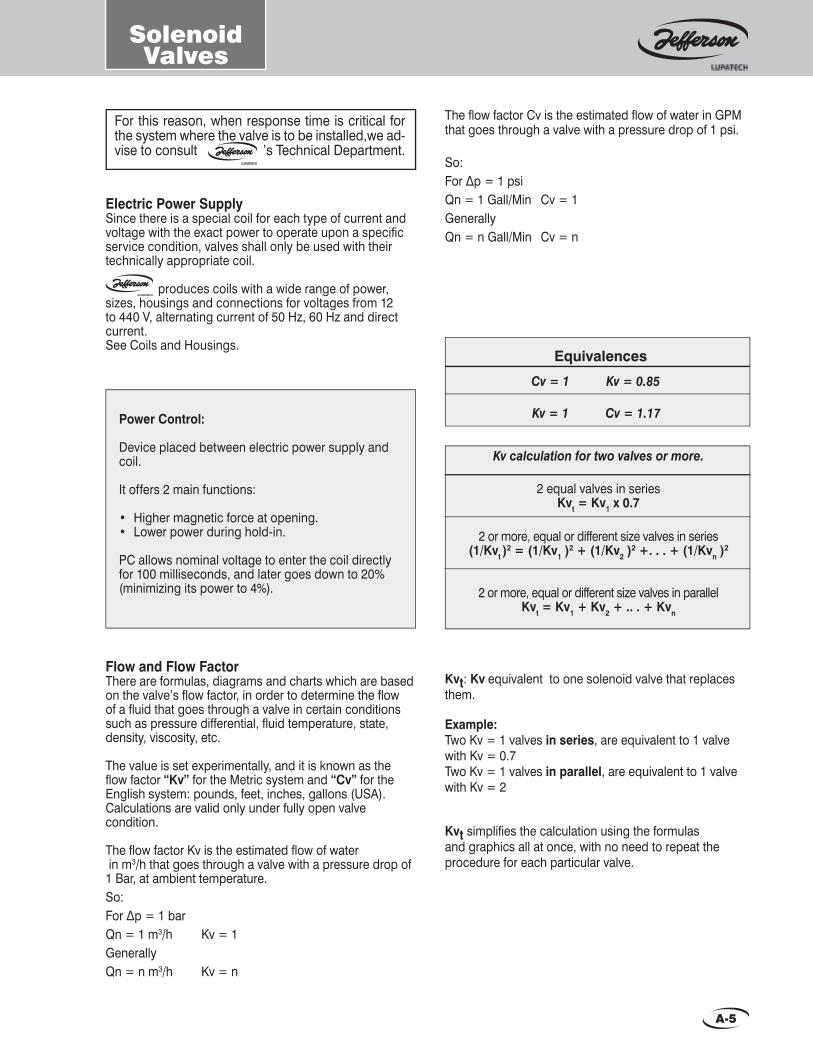
Electric Power SupplySince there is a special coil for each type of current and voltage with the exact power to operate upon a specifi c service condition, valves shall only be used with their technically appropriate coil.
produces coils with a wide range of power, sizes, housings and connections for voltages from 12 to 440 V, alternating current of 50 Hz, 60 Hz and direct current.See Coils and Housings.
Flow and Flow FactorThere are formulas, diagrams and charts which are based on the valve’s fl ow factor, in order to determine the fl ow of a fl uid that goes through a valve in certain conditions such as pressure differential, fl uid temperature, state, density, viscosity, etc.
The value is set experimentally, and it is known as the fl ow factor “Kv” for the Metric system and “Cv” for the English system: pounds, feet, inches, gallons (USA). Calculations are valid only under fully open valve condition.
The fl ow factor Kv is the estimated fl ow of water in m3/h that goes through a valve with a pressure drop of 1 Bar, at ambient temperature.So:For ∆p = 1 barQn = 1 m3/h Kv = 1GenerallyQn = n m3/h Kv = n
Kvt: Kv equivalent to one solenoid valve that replaces them.
Example:Two Kv = 1 valves in series, are equivalent to 1 valve with Kv = 0.7Two Kv = 1 valves in parallel, are equivalent to 1 valve with Kv = 2
Kvt simplifi es the calculation using the formulas and graphics all at once, with no need to repeat the procedure for each particular valve.
Equivalences
Kv calculation for two valves or more.
2 equal valves in series Kvt = Kv1 x 0.7
2 or more, equal or different size valves in series(1/Kvt )
2 = (1/Kv1 )2 + (1/Kv2 )
2 +. . . + (1/Kvn )2
2 or more, equal or different size valves in parallelKvt = Kv1 + Kv2 + .. . + Kvn
produces coils with a wide range of power,
Power Control:
Device placed between electric power supply and coil.
It offers 2 main functions:
• Higher magnetic force at opening.• Lower power during hold-in.
PC allows nominal voltage to enter the coil directly for 100 milliseconds, and later goes down to 20% (minimizing its power to 4%).
For this reason, when response time is critical for the system where the valve is to be installed,we ad-vise to consult ’s Technical Department.
The fl ow factor Cv is the estimated fl ow of water in GPM that goes through a valve with a pressure drop of 1 psi.
So:For ∆p = 1 psiQn = 1 Gall/Min Cv = 1GenerallyQn = n Gall/Min Cv = n
Cv = 1 Kv = 0.85 Kv = 1 Cv = 1.17
A-6
Tables andFormulas For fl ow calculation.
Metric units.
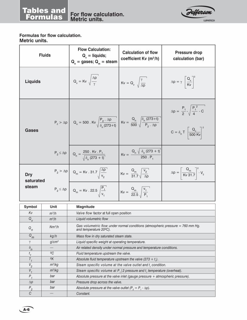
Formulas for fl ow calculation.Metric units.
Valve fl ow factor at full open position Liquid volumetric fl ow
Symbol Unit Magnitude
Kv Qv
QnNm3/h
m3/h m3/h
kg/h g/cm3 — ºC ºK m3/kg m3/kg barbar bar —
Gas volumetric fl ow under normal conditions (atmospheric pressure = 760 mm Hg. and temperature 20ºC).
Mass fl ow in dry saturated steam state. Liquid specifi c weight at operating temperature. Air related density under normal pressure and temperature conditions. Fluid temperature upstream the valve. Absolute fl uid temperature upstream the valve (273 + t1). Steam specifi c volume at the valve outlet and t1 condition. Steam specifi c volume at P12 pressure and t1 temperature (overheat). Absolute pressure at the valve inlet (gauge pressure + atmospheric pressure). Pressure drop across the valve. Absolute pressure at the valve outlet (P2 = P1 - ∆p).Constant.
Qm
γ
δn t1 T1 V2 V1 P1 ∆p P2 C
Flow Calculation: Qv = liquids;
Qn = gases; Qm = steam
Pressure drop calculation (bar)
Calculation of fl ow coeffi cient Kv (m3/h)
Fluids
Liquids
Dry
saturated steam
Gases
250 . Kv . P1
δn (273 + t)Qn =
Qn δn (273 + t)
250 . P1Kv =
Qm v2
31.7 ∆pKv =
Qm v1
22.5 P1Kv =
∆p
v2
Qm = Kv . 31.7
P1
v1
Qm = Kv . 22.5
∆p = γQv
2
Kv
∆p =P1 P1
2
2 4
C = δn T Qn
2
500 Kv
Kv = Qv
γ
∆p
Qn δn (273+t)
500 P2 . ∆pKv =
∆p
γQv = Kv
P2 . ∆p
δn (273+t)Qn = 500 . KvP2 > ∆p
P2 ≤ ∆p
P2 > ∆p
P2 ≤ ∆p
- - C
∆p = Qm 2
Kv 31.7 · V2

A-7
Tables andFormulas For fl ow calculation.
Metric units.
Relative density of some gases and liquids.
Gage pressure
bar
Specifi c Volumem3/kg
Temperature°C
At 20 °C and760 mm Hg
At operating temperature
Temp. in ºC
Air relateddensity
(δn)
S.W. g/cm3
(γ)
Gases Liquids
Some properties of dry saturated water steam.
(*) This is a representative value. According to its composition, it varies from 0.60 to 0.70.
1.060.901.000.721.382.071.531.272.491.050.971.450.140.071.191.501.900.550.65*1.040.971.531.101.661.562.262.26
0.790.790.810.650.850.901.331.210.830.840.890.900.900.750.810.911.150.801.200.510.570.760.921.020.880.871.00
15202015152020202020202020202020-50-160-1602020202020202015
2.09
1.69
1.69
1.43
1.33
1.16
1.03
0.89
0.78
0.69
0.61
0.52
0.46
0.43
0.38
0.34
0.32
0.28
0.27
0.26
0.24
0.23
0.22
0.20
0.19
0.19
0.18
93.5
99.6
102.3
104.8
107.1
111.4
115.2
120.2
124.7
128.7
133.5
138.9
143.6
147.9
151.8
156
159
161
165
168
170
173
175
177
180
182
184
0
0
0.1
0.2
0.3
0.5
0.7
1
1.3
1.6
2
2.5
3
3.5
4
4.5
5
5.5
6
6.5
7
7.5
8
8.5
9
9.5
10
AcetoneAcetylene
Air Ammonia
ArgonButane
Carbon dioxideChlorineEthaneEthane
EthyleneEthylene propane
HeliumHydrogen
Hydrogen sulfi deLPG grade 1LPG grade 2
MethaneNatural gas (*)
Nitric oxideNitrogen
Nitrous oxideOxygenOzone
PropaneSulphur dioxideSulphur oxide
AcetoneAlcohol ethil
Alcohol methylAmmoniaBenzeneDiesel oilFreon 12Freon 22
Fuel oil Nº 1Fuel oil Nº 2Fuel oil Nº 3Fuel oil Nº 4
GasoilGasolineKerosene
Light crude oil Liquid carbon dioxide
Liquid nitrogenLiquid oxygenLPG grade 1LPG grade 2
NaphtaOlive oilPhenol
SAE 10 (oil)Tupertine
Water

A-8
Tables andFormulas For fl ow calculation.
English units.
Formulas for fl ow calculation.English units.
Valve fl ow factor at full open position Liquid volumetric fl ow
Symbol Unit MagnitudeCv Qv
QnSCFH
GPM GPM
Gas volumetric fl ow under normal conditions (atmospheric pressure = 760 mm Hg. and temperature 68ºF).
Mass fl ow in dry saturated steam state. Specifi c gravity at operating temperature. Specifi c gravity under normal pressure and temperature conditions. Fluid temperature upstream the valve. Absolute fl uid temperature upstream the valve (460 + t1). Steam specifi c volume at the valve outlet and t1 condition. Steam specifi c volume at P12 pressure and t1 temperature. Absolute pressure at the valve inlet (gauge pressure + atmospheric pressure). Pressure drop across the valve. Absolute pressure at the valve outlet (P2 = P1 - ∆p).Constant.
Qm
γ
δn t1 T1 V2 V1 P1 ∆p P2 C
lb/h — — ºF ºR ft3/lb ft3/lb psiapsi psia —
Pressure drop calculation (psi)
Calculation of fl ow coeffi cient Cv (GPM)
Fluids
Liquids
Dry
saturated steam
Gases
∆p = γQv
2
Kv
∆p =P1 P1
2
2 4
C = δn T Qn
2
1412 Cv
Cv = Qv
γ
∆p
Qn δn (460+t)
1412 P2 . ∆pCv =
∆p
γQv = Kv
P2 . ∆p
δn (460+t)Qn = 1412 . Cv
∆p = Qm 2
Cv 64.2
Qn δn (460 + t)
706 . P1Cv =
Qm v2
64.2 ∆pCv =
Qm v1
45.4 P1Cv =
706 . Cv . P1
δn (460 + t)Qn =
∆p
v2
Qm = Cv . 64.2
P1
v1
Qm = Cv . 45.4
P2 > ∆p
P2 ≤ ∆p
P2 > ∆p
P2 ≤ ∆p
Flow Calculation; Qv = liquids;
Qn = gases; Qm = steam
- - C
· V2

A-9
Tables andFormulas For fl ow calculation.
English units.
Specifi c gravity of some gases and liquids.
Gage pressure
psig
Specifi c Volume
ft3/lbTemperature
°FAt 68 °F and760 mm Hg
At operating temperature
Temp. in °F
Specifi cgravity
(δn)
Specifi c gravity
(γ)
Gases Liquids
(*) This is a representative value. According to its composition, it varies from 0.60 to 0.70.
Some properties of the dry saturated water steam.
-302467101520253035404550556065708090100110120130140145
33.2
26.8
23.6
21.4
19.4
18.6
16.4
13.9
12
10.6
9.16
8.57
7.83
7.21
6.68
6.23
5.38
5.49
5.19
4.67
4.24
3.89
3.59
3.34
3.12
2.93
2.84
200.7
212
218.7
224.4
230
232
240
250
259
267
274
281
287
292
298
302
307
311
316
324
331
338
344
350
356
361
363
1.060.901.000.721.382.071.531.272.491.050.971.450.140.071.191.501.900.550.65*1.040.971.531.101.661.562.262.26
0.790.790.810.650.850.901.331.210.830.840.890.900.900.750.810.911.150.801.200.510.570.760.921.020.880.871.00
59686859596868686868686868686868-58-256-2566868686868686859
AcetoneAcetylene
Air Ammonia
ArgonButane
Carbon dioxideChlorineEthaneEthane
EthyleneEthylene propane
HeliumHydrogen
Hydrogen sulfi deLPG grade 1LPG grade 2
MethaneNatural gas (*)
Nitric oxideNitrogen
Nitrous oxideOxygenOzone
PropaneSulphur dioxideSulphur oxide
AcetoneAcohol ethyl
Acohol methylAmmoniaBenzeneDiesel oilFreon 12Freon 22
Fuel oil Nº 1Fuel oil Nº 2Fuel oil Nº 3Fuel oil Nº 4
GasoilGasolineKerosene
Light crude oil Liquid carbon dioxide
Liquid nitrogenLiquid oxygenLPG grade 1LPG grade 2
NaphtaOlive oilPhenol
SAE 0 (oil)Tupertine
Water

A-10
PRESSURE DROP
INSTRUCTIONS
Example 1: Determine the fl ow:Data: Pressure drop: 0.25 bar; Density: 2; Kv: 1.4
Solution: Start from pressure differential = 0.25 bar. (Scale 2)Read: fl ow = 0.50 m3/h (Scale 2)
Example 2: Determine Kv:Data: Pressure differential: 100 mm w.c. Density: 1 (water); fl ow: 4 m3/h
Solution: Start from pressure drop = 100 mm w.c. (scale 1) to fl ow crossing point = 4 m3/h (scale 1). Read: Kv = 40
Example 3: Determine the pressure drop:Data: Flow: 2000 m3/h; Kv: 600: Density: 0.7.
Solution: Start from fl ow = 2000 m3/h (scale 2). Read: pressure drop = 8 bar (scale 2).
Kv F
acto
r
FLO
W IN
m3 /
h
FlowChart For liquids.
A-11
FlowChart
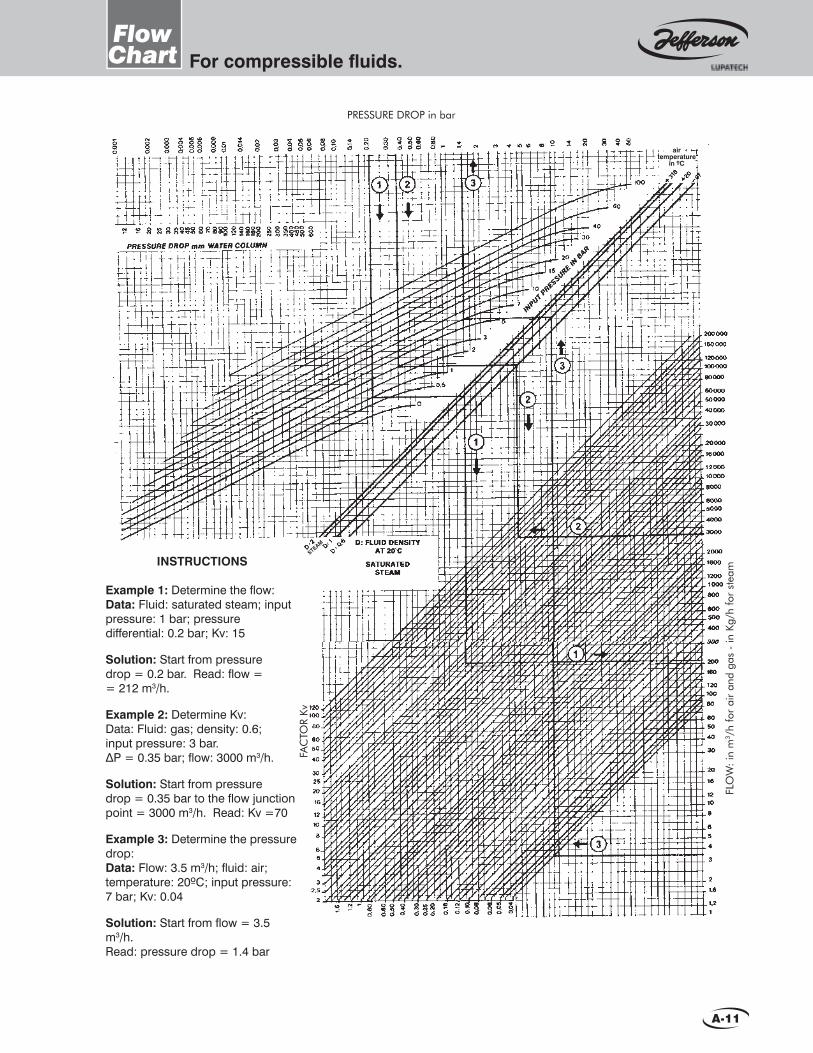
PRESSURE DROP in bar
INSTRUCTIONS
Example 1: Determine the fl ow:Data: Fluid: saturated steam; input pressure: 1 bar; pressure differential: 0.2 bar; Kv: 15
Solution: Start from pressure drop = 0.2 bar. Read: fl ow = = 212 m3/h.
Example 2: Determine Kv:Data: Fluid: gas; density: 0.6; input pressure: 3 bar. ∆P = 0.35 bar; fl ow: 3000 m3/h.
Solution: Start from pressure drop = 0.35 bar to the fl ow junction point = 3000 m3/h. Read: Kv =70
Example 3: Determine the pressure drop:Data: Flow: 3.5 m3/h; fl uid: air; temperature: 20ºC; input pressure: 7 bar; Kv: 0.04
Solution: Start from fl ow = 3.5 m3/h. Read: pressure drop = 1.4 bar
FLO
W:
in m
3 /h
for
air
and
gas
- in
Kg/
h fo
r st
eam
FAC
TOR
Kv
STEAM
air temperature
in ºC
For compressible fl uids.
A-12
Maincharacteristics.
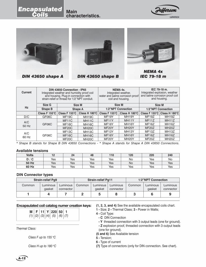
EncapsulatedCoils
Encapsulated coil catalog numer creation keys: (1, 2, 3, and 4) See the available encapsulated coils chart.1 - Size; 2 - Thermal Class; 3 - Power in Watts; 4 - Coil Type: - C DIN Connection - Y threaded connection with 3 output leads (one for ground). - Z explosion proof, threaded connection with 3 output leads (one for ground).(5 and 6) See Available tension5 - Tension; 6 - Type of current(7) Type of connectors (only for DIN connection. See chart).
DIN 43650 shape BNEMA 4x
IEC 79-18 m
NEMA 4xIEC 79-18 mDIN 43650 shape ADIN 43650 shape A
M F 11 Y 220 50 1 (1) (2) (3) (4) (5) (6) (7)
Thermal Class: Class F up to 155 °C Class H up to 180 °C
Common
1
Luminousgasket
4
Luminousconnector
7
Common
2
Luminousgasket
5
Luminousconnector
8
Common
3
Luminousgasket
6
Luminousconnector
9
Strain-relief Pg9 Strain-relief Pg11 1/2”NPT ConnectionDIN Connector types
Available tensionsVoltsD / C50 Hz60 Hz
12YesYesYes
24 48 110 120NoNoYes
220YesYesYes
240NoYesYes
YesYesYes
YesYesYes
YesYesYes
* Shape B stands for Shape B DIN 43650 Connections - * Shape A stands for Shape A DIN 43650 Connections.
Current
HzSize M
Shape ASize M
1/2”NPT ConnectionSize M
1/2”NPT ConnectionSize G
Shape BClass H 180°CClass F 155°CClass H 180°CClass F 155°CClass H 180°CClass F 155°C
DIN 43650 Connection - IP65Integrated weather and humidity proof coil
and housing. Plug-in connection with strain-relief or thread for 1/2’’NPT conduit.
NEMA 4x.Integrated weather,
water and saline corrosion proof coil and housing.
IEC 79-18 m.Integrated explosion, weather and saline corrosion proof coil
and housing.
Class F 155°CMF19CMF11CMF16CMF20CMF13CMF16CMF20C
MF19YMF11YMF16YMF20YMF13YMF16YMF20Y
MH19YMH11YMH16YMH20YMH13YMH16YMH20Y
MF19ZMF11ZMF16ZMF20ZMF13ZMF16ZMF20Z
MH19ZMH11ZMH16ZMH20ZMH13ZMH16ZMH20Z
MH19CMH11CMH16CMH20CMH13CMH16CMH20C
GF06C
GF06C
GF06C
D/C
A/C50 Hz
A/C60 Hz

A-13
Maincharacteristics.
Non capsulated coilsand housings
Non capsulated coil housings
Coated with glass fi bre and insulating impregnation.Terminal cables for splicing.
S 20 H 220 50 (1) (2) (3) (4) (5)
Catalog number information:(1, 2 and 3) See fi bre coated coils chart.1 - Coil size; 2 - Power in Watts; 3 - Thermal class. P = class H + polyester coating.(4 and 5) See available tensions chart.4 - Tension.5 - Current.
Thermal Class: Class F up to 155ºC Class H up to 180ºC
(1) Without rectifi er bridge. (2) With rectifi er bridge, only 110, 120, 220 and 240 V available. (3) Class H + polyester coating.
Current Size M Size B
M11FM16F
M13FM16F
S28F
S48HS60H (1)
S28HS46H
S46P (3)S60H (2)
S30HS46HS46P
S60H (2)
B113H (1)
B113H (2)
B113H (2)
Size S
M19H
M11HM16H
M13HM16H
Class H 180°CClass H 180°CClass F 155°CClass H 180°CClass F 155°C
D/C
A/C50 Hz
A/C60 Hz
Available Tensions - Size M and SVolts 12
YesYesYes
24YesYesYes
48YesYesYes
110YesYesYes
120NoNoYes
220YesYesYes
240NoYesYes
380NoYesNo
440NoNoYes
D / C50 Hz60 Hz
General internal
use
Weather and water proof (Prefi x Y)
Explosion and weather
proof (Prefi x Z)
M S S (for 2088) BClassifi cation Coil size
Plate hole forØ19 mm electric
connection. Ground terminal
(Suffi x C)
Aluminium epoxypaint
1/2” BSP or NPTconnection
NEMA 4x and IP65
Aluminium epoxypaint
1/2” BSP or NPT connection
CastIron
3/4” NFConnector
Cast ironepoxy paint1/2” BSP or
NPT connectionNEMA 4x and IP65
Ironepoxy paint1/2” BSP or
NPT connection According to IEC
79 1 “d”
Painted castiron
1/2” BSPor NPT
Connector
Cast ironepoxy paint1/2” BSP or
NPT connectionNEMA 4x and IP65
Ironepoxy paint1/2” BSP or
NPT connection According to IEC
79 1 “d”
Painted castiron
1/2” BSPor NPT
Connector
Cast ironepoxy paint1/2” BSP or
NPT connectionNEMA 4x and IP65
Ironepoxy paint1/2” BSP or
NPT connection According to IEC
79 1 “d” ATEX - Directive 94 / 9 CE
II 2G Ex d IIB T3ATEX - Directive 94 / 9 CE
II 2G Ex d IIB T3

A-14
Solenoid andpneumatically operated valves.
SelectionGuide
General Purpose
1314
1327
1335
1342
1390
1393
2026
2036
2036V
Connection (ins.) Maximum Temp. °C
∆ppsi Fluids or typical applications
Min
imum
Max
imum
Air a
nd
iner
t gas
esW
ater
and
lig
ht li
quid
sTh
erm
al
oils
Stea
m
Oxy
gen
Gas
olin
e
Vacu
umSerie
s
0
0
0
3
1.5
0
0
3
4.5
225
1500
150
255
225
60
750
225
150
A
A
A
A
A
T
A
A
-
A
A
A
A
A
T
A
A
-
T
T
V
T
T
T
-
-
-
T
T
E
T
T
T
E
-
T
N
N
N
N
N
-
N
-
-
V
V
V
V
V
-
V
-
-
A-V
A-V
A-V
-
-
-
A-V
-
-
1/8 1801/4 3/8 1/2 3/4 1 11/2 2 21/2 3 80 150
Note: 1327, 1335, 1342, 1390, y 1393 NC and NO.
∆pbar
Min
imum
Max
imum
0
0
0
0.2
0.1
0
0
0.2
0.3
15
100
10
17
15
4
50
15
10
Page
B-2
B-4
B-6
B-8
B-10
B-12
B-14
B-16
B-16
Nomenclature: The letters indicated in Typical Applications refer to the seat, seal and diaphragm materials (if any), as follows: A = Buna N; N = Neoprene; E = EPDM; V = FKM; T = PTFE, S = AISI 304.
Combustion Use
1312
1330
2030
1332
1356
1388
1327
2026
1335
1390
2088
V171
Connection (ins.)
Serie
s
1/8 1/4 3/8 1/2 3/4 1 11/2 2 21/2 3
N. C
lose
d
N. O
pen
∆ppsi
Min
imum
Max
imum
0
0
0.015
0
0
0
0
0
0
0.1
0
0
315
3
30
45
300
75
300
150
150
225
45
22.5
-
-
-
-
-
-
-
-
-
-
-
-
-
-
-
-
-
-
-
-
-
-
-
Man
ual R
eset
Posi
tion
ind.
Slow
ope
ning
S
-
-
-
T
-
V
V
V
V
-
-
Fluids
Gas
oil
Fuel
oil
Nat
ural
V
LPG
Com
bust
ion
Air
S
-
-
-
T
-
T
-
-
-
-
-
-
A
A
A
T
A
A
A
A
A
A
A
A
A
A
A
T
A
A
A
A
A
A
A
A
A
A
A
-
A
A
A
A
A
A
-
∆pbar
Min
imum
Max
imum
0
0
0.001
0
0
0
0
0
0
0.1
0
0
21
0.2
2
3
20
5
20
10
10
15
3
1.5
Page
C-8
C-10
C-10
C-12
C-14
C-16
B-4
B-14
B-6
B-10
C-20
C-23 Thermoelectricsafety valve
-
-
-
-
-
-

A-15
Solenoid andpneumatically operated valves.
SelectionGuide
Valves and devices for special service.Connection (ins.)
Max
imum
Te
mpe
ratu
re
Serie
s
1/8 81/4 3/8 1/2 3/4 1 11/2 2 21/2 3 4 6Page
2073
1360
1369
1372
1310
1311
176
140
176
176
572
302
Solenoid Valves for Corrosives Fluids
Solenoid Valves with Manual Reset Device
Valves with Pneumatic or Hydraulic Operators
Pneumatically or Hydraulically Operated Valves
Solenoid Valves for Dust Collector Systems80
60
80
80
300
150Note: 1310, special construction for higher temperature and pressure.
E-10
E-6
E-8
E-11
E-2
E-4
Continues in next page
150
60
300
150
300
105
10
4
20
10
20
7
Max
imum
pr
essu
re
Fluids or typical applications
Auxi
liary
Flu
ids
Acid
s
Alka
lisDi
still
ate
wat
er
Dirty
Flu
ids
Neut
ral G
ases
an
d Ai
rTh
erm
al O
ils
Oil
Prod
ucts
no
no
no
yes
yes
yes
0 C 0 F bar psi
-
-
-
-
-
-
- - -
-
-
-
-
-
-
-
-
Pneumatic and hydraulic use.
1323
1325
1339
1350
1351
1365
1375
1387
1387
2050
2051
2095
2024
Connection (ins.) 3 WaysSe
ries
1/8 1/4 3/8 1/2 3/4
MaximumMinimum
NC NO
0
0.5
-
-
0.5
0
-
0
0.5
-
0.5
0.8
-
0
7.5
-
-
7.5
0
-
0
7.5
-
7.5
12
-
12
10
-
-
10
15
-
10
10
-
10
8
-
180
150
-
-
150
225
-
150
150
-
150
120
-
12
10
-
-
10
15.5
-
-
-
-
10
-
-
180
150
-
-
150
232
-
-
-
-
150
-
-
NAMUR
NAMUR
NAMUR
2
2
3
2
2
2
2
2
2
2
2
2
2
A
A
A
A
A
A
A
A
A
A
A
A
A
A
A
A
A
A
A
A
A
A
A
A
A
A
A
A
A
A
A
A
-
-
-
A
A
-
-Po
sitio
ns
Mon
osta
ble
Bist
able
Fluids
Lubr
icat
ed
Air
Dry
Air
Gas
Wat
er
Hyd
raul
ic O
il
A
A
A
A
A
A
-
-
-
A
A
-
-
A
A
A
A
A
A
-
-
-
A
A
-
-
bar
psi
U
bar
psi
bar
psi
bar
psi
bar
psi
4 & 5 Ways
Minimum Maximum
bar
psi
Page
D-2
D-4
D-6
D-8
D-10
D-12
D-14
D-15
D-15
D-16
D-18
D-20
D-24
NAMUR
8
-
-
-
-
9
-
-
-
-
-
-
-
120
-
-
-
-
135
-
-
-
-
-
-
-
-
-
0.5
0.5
-
-
0.5
-
-
0.5
-
0.8
0.8
-
-
10
10
-
-
10
-
-
10
-
12
12
-
-
10
10
-
-
10
-
-
10
-
8
10
-
-
150
150
-
-
150
-
-
150
-
120
150
-
-
-
-
-
-
-
-
-* Hot Air or Gas: FKM Seats or Seals - NC: Normally Closed. NO: Normally Open. Div: Divergent. Con: Convergent.
A-16
Solenoid andpneumatically operated valves.
SelectionGuide
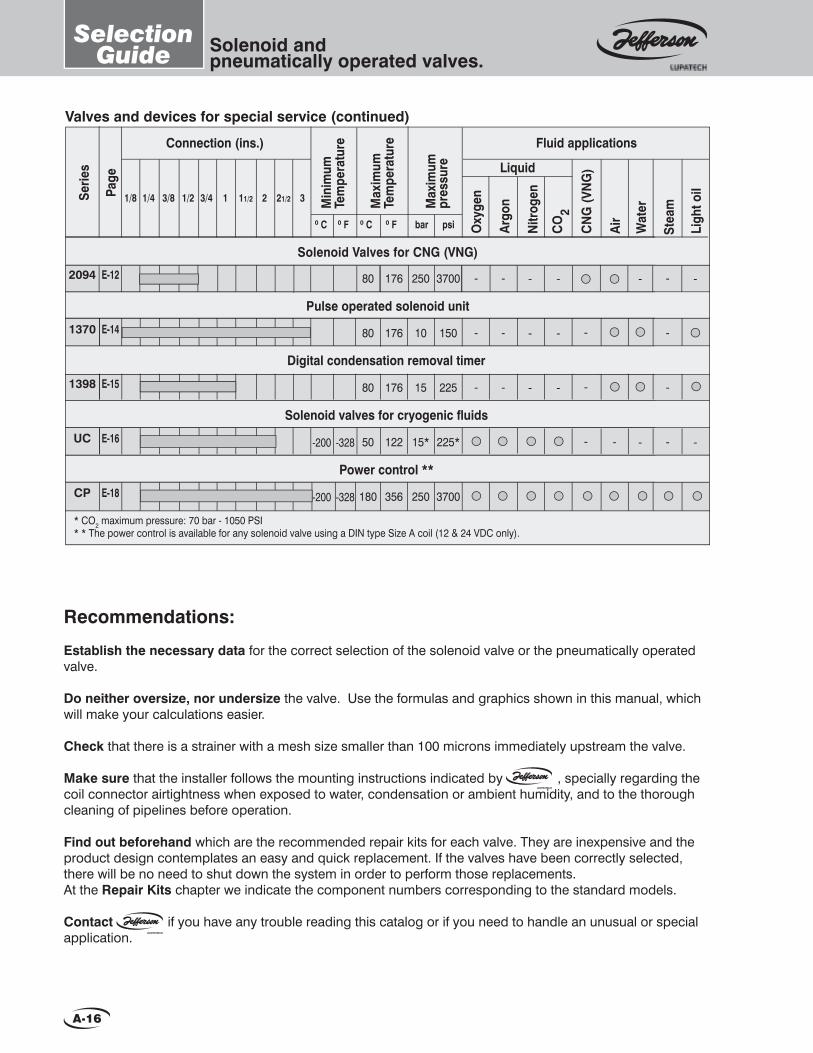
Valves and devices for special service (continued)
Connection (ins.)
Max
imum
Te
mpe
ratu
re
Serie
s
1/8 1/4 3/8 1/2 3/4 1 11/2 2 21/2 3Page
2094
1370
1398
UC
CP
176
176
176
122
356
Pulse operated solenoid unit
Digital condensation removal timer
Solenoid valves for cryogenic fl uids
Solenoid Valves for CNG (VNG)
80
80
80
50
180
E-12
E-14
E-15
E-16
E-18
3700
150
225
225*
3700
250
10
15
15*
250
Max
imum
pr
essu
re
Fluid applications
Nitr
ogen
CO
2
CN
G (V
NG
)
Wat
er
Stea
m
Ligh
t oil
Air0 C 0 F bar psi
-
-
-
-
-
-
-
-
-
-
Power control **
Min
imum
Tem
pera
ture
0 C 0 F
Liquid
Oxy
gen
Argo
n
-
-
-
--200
-200
-328
-328
-
-
-
* CO2 maximum pressure: 70 bar - 1050 PSI* * The power control is available for any solenoid valve using a DIN type Size A coil (12 & 24 VDC only).
-
-
-
-
-
-
-
Recommendations:
Establish the necessary data for the correct selection of the solenoid valve or the pneumatically operated valve.
Do neither oversize, nor undersize the valve. Use the formulas and graphics shown in this manual, which will make your calculations easier.
Check that there is a strainer with a mesh size smaller than 100 microns immediately upstream the valve.
Make sure that the installer follows the mounting instructions indicated by , specially regarding the coil connector airtightness when exposed to water, condensation or ambient humidity, and to the thorough cleaning of pipelines before operation.
Find out beforehand which are the recommended repair kits for each valve. They are inexpensive and the product design contemplates an easy and quick replacement. If the valves have been correctly selected, there will be no need to shut down the system in order to perform those replacements. At the Repair Kits chapter we indicate the component numbers corresponding to the standard models.
Contact if you have any trouble reading this catalog or if you need to handle an unusual or special application.
coil connector airtightness when exposed to water, condensation or ambient humidity, and to the thorough

B-1
1314 1327 1335
1390 1393
2026
2 WaySolenoid Valves for General Purpose.
1359
2036 2036 V
1342
1359 Series “Y” strainer for general purpose. B-18
Normally closed. Pilot operated.
2036 Series B-16 / B-17
Normally closedMicrovalveDirect acting.
2026 Series
B-14 / B-15
Normally closedand Normally openDirect acting.
1393 Series
B-12 / B-13
Normally closed and Normally open.Pilot operated.
1390 Series
B-10 / B-11
1342 Series Normally closed and Normally open.Pilot operated. B-8 / B-9
1335 Series Normally closed and Normally open.Direct acting or pilot operated. B-6 / B-7
Normally closedand Normally open.Direct acting.
1327 Series
B-4 / B-5
1314 Series Normally closedPilot operated. B-2 / B-3
Pages
To request a technical bulletin for models that are not included in this catalog, please contact JEFFERSON at:
New products NEW SOLENOID VALVE MODELS
Intrinsically Safe. Vacuum Systems. Hydraulic, Water Hammer-Proof. ATEX Explosion-Proof Coils.
B-16 / B-172036V Series Normally closed,
for steam.
Pages
B-2
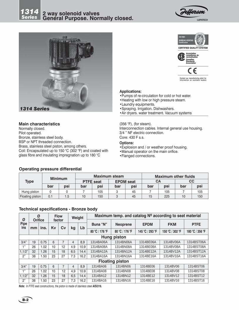
2 way solenoid valvesGeneral Purpose. Normally closed.
1314Series
Main characteristicsNormally closed.Pilot operated.Bronze, stainless steel body.BSP or NPT threaded connection.Brass, stainless steel piston, among others.Coil: Encapsulated up to 150 °C (302 °F) and coated with glass fi bre and insulating impregnation up to 180 °C
(356 °F), (for steam).Interconnection cables. Internal general use housing. 3/4 ” NF electric connection.Core: 430 F s.s.Options:•Explosion and / or weather proof housing.•Manual operator on the main orifi ce.•Flanged connections.
1314 Series
Applications:•Pumps of re-circulation for cold or hot water.•Heating with low or high pressure steam.•Laundry equipments.•Spraying. Irrigation. Dishwashers.•Air dryers. water treatment. Vacuum systems
CanadianStandardsAssociation
Associationcanadienne denormalisation
CERTIFIED QUALITY SYSTEM
Contact our manufacturing plant forin format ion on ava i lab le models
Buna “N” Neoprene EPDM FKM PTFEkgCvmm ins. Kv
Maximum temp. and catalog Nº according to seat materialFlowfactor
Technical specifi cations - Bronze body
3/4”1”
1,1/2”2”
3/4”1”
1,1/2”2”
Floating piston
Hung piston
Note: In PTFE seat constructions, the piston is made of stainless steel AISI316.
Weight
19263238
Lb
6101523
1314BA06A1314BA08A1314BA12A1314BA16A
1314BN06A1314BN08A1314BN12A1314BN16A
1314BE06A1314BE08A1314BE12A1314BE16A
1314BV06A1314BV08A1314BV12A1314BV16A
44.96.57.3
1314BST06A1314BST08A1314BST12A1314BST16A
0.75 1.021.261.50
7121827
8,910.914.416.2
6101523
1314BA061314BA081314BA121314BA16
1314BN061314BN081314BN121314BN16
1314BE061314BE081314BE121314BE16
1314BV061314BV081314BV121314BV16
44,96,57,3
19263238
1314BST061314BST081314BST121314BST16
8,910.914.416.2
0.75 1.021.261.50
7 121827
Typebar psi bar
Maximum other fl uidsMinimum
Operating pressure differential
Hung pistonFloating piston
00.1
01.5
715
psi105225
bar psiCA CC
710
105150
Maximum steam
psi7
10105150
barPTFE seat
bar33
4545
psiEPDM seat
80 °C / 176 °F 80 °C / 176 °F 145 °C / 293 °F 150 °C / 302 °F 180 °C / 356 °F
ØPipeins
Ø Orifi ce
B-3
2 way solenoid valvesGeneral Purpose. Normally closed.
1314Series
Special constructionsStainless steel body:•AISI304: change letter B or BS for S in the catalog Nº. Example: 1314SA08, 1314ST08.•AISI316: change letter B or BS for I in the catalog Nº. Example: 1314IA08, 1314IT08.
Recommendations for installationPlace a strainer with a porosity ≤ 100µ upstream the valve. Mount the valve only over horizontal pipeline with the coil upright.The valve input pressure must always be equal or greater than the output pressure.
Application according to seat material
Buna “N” NeopreneSeat material EPDM
Maximum temperature
FKM PTFE
Water, air, light oils. Neutral gases.
Kerosene, low and medium vacuum
Oxygen, alcohol, argon, other
non-corrosive light gases and liquids,
Freon 12.
Steam, hot oils,
corrosive fl uids.
Water steam, hot water, acetone.
Benzene, naphta, aromatics, etc. hot
gases,high vacuum,
diesel oil.
Uses
(*) For steam1-(12,24,110,220,240)V 2-(12,24,110,120,220,240)V 3-(12,24,110,220)V
Coil characteristicsElectricpowersupply
Availabletensions
Coiltype
PowerW
VA (volt-amper)
Inrush SH28CS28H (*)SH30CS30H (*)SH48S48H (*)
282830304848
2412522672374848
697380784848
112233
Holding
Maximumtemperature
0C 0F155180 155 180 155180
311356311356311356
Measurements: ins.
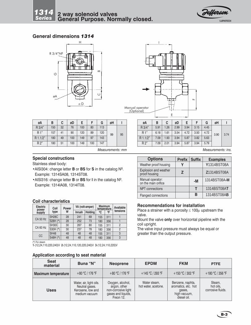
B CøA øD E F G øH I5.916.187.097.09
1.261.611.932.01
2.993.543.943.94
3.944.725.875.87
R 3/4”R 1”
R 1.1/2”R 2”
3.153.503.823.94
4.454.725.635.79
3.90 3.74
OptionsWeather proof housingExplosion and weather proof housingManual operator:on the main orifi ceNPT connections
Flanged connections
Prefi x Y
Z
Examples Suffi xY1314BST08A
Z1314BST08A
1314BST08A-M
1314BST08AT1314BST08AB
-M
TB
General dimensions 1314H
CB
R 3/4”NF
Ø D
øA
G
E
F
Manual operator(Optional)
I
Measurements: mm
B CøA øD E F G øH I150157180180
32414951
7690
100100
100120149149
R 3/4”R 1”
R 1.1/2”R 2”
808997
100
113120143147
99 95
CA 50 Hz
CA 60 Hz
CC
+80 °C / 176 °F +80 °C / 176 °F +145 °C / 293 °F +150 °C / 302 °F +180 °C / 356 °F

B-4
2 way solenoid valvesGeneral purpose.
1327Series
Main characteristicsNormally closed and normally open.Direct action. No minimum differential pressure to operate.1/4” BSP or NPT threaded connections. Brass, iron, stainless steel body.Core tube AISI 304 and 316.Plunger and fi xed core AISI 430 F.Shading coil: copper, silver or aluminiumShape A DIN 43650 connection encapsulated coils.IP65 and NEMA 4 protection.Approximate weight: 0.5 kg. (1.1Lb)
Options:•Energized coil indicator light.•Explosion and / or weather proof coils and housings.•Manual operator.
1327 Series
UnderwritersLaboratories Inc.®
CERTIFIED QUALITY SYSTEM
Applications:•Instrumentation. Laboratory. •Burner pilot for combustible gases and liquids.•Welding equipment. Humidifi ers. •Dental equipment. Vacuum systems.•Laundry and dry cleaning machines.•Heating with low or high pressure steam
Contact our manufacturing plantfor information on available models
1.251.752.253.004.005.005.25
0.050.090.130.260.430.600.65
1327BA1221327BA1721327BA2221327BA3021327BA4021327BA5021327BA522
*35201053
2.2
1327BE1221327BE1721327BE2221327BE3021327BE4021327BE5021327BE522
1327BV1221327BV1721327BV2221327BV3021327BV4021327BV5021327BV522
1327BN1221327BN1721327BN2221327BN3021327BN4021327BN5021327BN522
1327BT1221327BT1721327BT2221327BT3021327BT402
--
1.251.752.252.503.004.00
0.050.090.130.170.260.43
1327BA122NA1327BA172NA1327BA222NA1327BA252NA1327BA302INA1327BA402INA
50**20**12**10105
1327BE122NA1327BE172NA1327BE222NA1327BE252NA1327BE302INA1327BE402INA
1327BV122NA1327BV172NA1327BV222NA1327BV252NA1327BV302INA1327BV402INA
1327BN122NA1327BN172NA1327BN222NA1327BN252NA1327BN302INA1327BN402INA
1327BT122INA1327BT172INA1327BT222INA
-1327BT302INA1327BT402INA
.049
.068
.088
.118
.157
.197
.206
0.060.110.150.300.500.700.76
*525300150754533
0.060.110.150.200.300.50
750**300**180**15015075
.049
.068
.088
.098
.118
.157
Buna “N” Neoprene EPDM FKM PTFEpsibarmm ins. Kv Cv
Maximum temp. and catalog Nº according to seat material∆p (a) maximum
Flowfactor
Normally closed
Technical specifi cations - Brass body
Normally open
(a)Advise: when using direct current (DC), a 25% reduction on the maximum operating pressure differential is expected.
** With PTFE seat, maximum pressure 10bar / 150psi.
80 °C / 176 °F 80 °C / 176 °F 145 °C / 293 °F 150 °C / 302 °F 180 °C / 356 °F
Orifi ceØ
* With PTFE seat 100 bar/1500 psi. Other seats 70 bar/1500 psi.

B-5
2 way solenoid valvesGeneral purpose.
1327Series
Special constructionsStainless steel body.•AISI 304: change letter B for S in the catalog Nº. Example: 1327ST302•AISI 316: change letter B for I in the catalog Nº. Example: 1327IT302.
Recommendations for installationPlace a strainer upstream the valve with a porosity ≤ 100µ. Any mounting position.The valve allows > output pressure than input pressure, but in these cases watertightness is not guaranteed when it is closed.
OptionsWater, weather and saline corrosion proof coils. Explosion and weather proof coils.Weather proof housing.Explosion and weather proof housing.Manual operator:on the main orifi ce NPT connections
Prefi x YC
ZC
Y
Z
Examples Suffi xYC1327BA302
ZC1327BA302
Y1327BA302
Z1327BA302
1327BA302-M
1327BA122T
- M
T Energized coil indicator light See coils.
1-(12,24,110,220,240)V 2-(12,24,110,120,220,240)V 3-(12,24,110,220)V
Coil characteristicsElectricpowersupply
AC 50 Hz
AC 60 Hz
DC
Availabletensions
MaximumtemperatureCoil
typePower
WVA (volt-amper)
Inrush MF11CMH11CMF13CMH13CMH19C
1111131319
4040454519
2222272719
11223
Holding 0 C 0 F155 180 155 180 180
311356311356356
Application according to seat material
Buna “N” NeopreneSeat material EPDM
Maximum temperature
FKM PTFE
Water, air, light oils. Neutral gases.
Kerosene, low and medium vacuum
Oxygen, alcohol, argon, other
non-corrosive light gases and liquids,
Freon 12.
Steam, hot oils,
corrosive fl uids.
Water steam, hot water, acetone.
Benzene, naphta, aromatics, etc. hot
gases,high vacuum,
diesel oil.
Uses
General dimensions 1327B
CF
R 1/4”
R.W 3/16”
G
D
NC
Pg9
E
E VIEW
E
INA
/NA
Measurements: mm Measurements: ins.80
NC NA B89
C D57 22 10
E F G85 27 20
INA102 3.15
NC NA B3.50
C D2.24 0.87 0.39
E F G3.35 1.06 0.79
INA4
* Up to 20 bar - 300 psi. PTFE seat not available. Only NC versions.( )
*( )
+80 °C / 176 °F +80 °C / 176 °F +145 °C / 293 °F +150 °C / 302 °F +180 °C / 356 °F
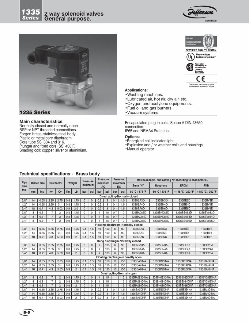
B-6
2 way solenoid valvesGeneral purpose.
1335Series
Main characteristicsNormally closed and normally open.BSP or NPT threaded connections.Forged brass, stainless steel body.Plastic or metal core diaphragm.Core tube SS. 304 and 316.Plunger and fi xed core: SS. 430 F.Shading coil: copper, silver or aluminium.
Encapsulated plug-in coils. Shape A DIN 43650connection.IP65 and NEMA4 Protection.Options:•Energized coil indicator light.•Explosion and / or weather coils and housings.•Manual operator.
1335 Series
Applications:•Washing machines.•Lubricated air, hot air, dry air, etc.•Oxygen and acetylene equipments.•Fuel oil and gas burners.•Vacuum systems.
UnderwritersLaboratories Inc.®
CanadianStandards Association
Associationcanadienne denormalisation
CERTIFIED QUALITY SYSTEM
Contact our manufacturing plantfor information on available models
Technical specifi cations - Brass body
Pipe size ins.
Orifi ce size Flow factor Weight Pressure minimum
Pressure maximum
AC
Pressure maximum
DC
Maximum temp. and catalog Nº according to seat material.
Buna “N” Neoprene EPDM FKM
mm ins Kv Cv Kg Lb bar psi bar psi bar psi 80 °C / 176 °F 80 °C / 176 °F +145 °C / 293 °F +150 °C / 302 °FDirect acting-Normally closed
3/8” 14 0.55 2.35 2.75 0.8 1.75 0 0 0.2 3 0.1 1.5 1335BA3D 1335BN3D 1335BE3D 1335BV3D1/2” 14 0.55 2.65 3.1 0.8 1.75 0 0 0.2 3 0.1 1.5 1335BA4D 1335BN4D 1335BE4D 1335BV4D3/4” 18 0.71 4.3 5.03 0.9 2.0 0 0 0.2 3 0.1 1.5 1335BA6D 1335BN6D 1335BE6D 1335BV6D3/8” 8 0.31 1.7 2 0.8 1.75 0 0 1 15 0.7 10 1335BA083D 1335BN083D 1335BE083D 1335BV083D1/2” 8 0.31 1.7 2 0.8 1.75 0 0 1 15 0.7 10 1335BA084D 1335BN084D 1335BE084D 1335BV084D3/4” 8 0.31 1.7 2 0.9 2 0 0 1 15 0.7 10 1335BA086D 1335BN086D 1335BE086D 1335BV086D
Floating diaphragm-Normally closed3/8” 14 0.55 2.35 2.75 0.8 1.75 0.1 1.5 10 150 6 90 1335BA3 1335BN3 1335BE3 1335BV3 1/2” 14 0.55 2.65 3.1 0.8 1.75 0.1 1.5 10 150 6 90 1335BA4 1335BN4 1335BE4 1335BV43/4” 18 0.71 4.3 5.03 0.9 2 0.1 1.5 10 150 6 90 1335BA6 1335BN6 1335BE6 1335BV6
Hung diaphragm-Normally closed3/8” 14 0.55 2.35 2.75 0.8 1.75 0 0 7 105 6 90 1335BA3A 1335BN3A 1335BE3A 1335BV3A1/2” 14 0.55 2.65 3.1 0.8 1.75 0 0 7 105 6 90 1335BA4A 1335BN4A 1335BE4A 1335BV4A3/4” 18 0.71 4.3 5.03 0.8 2 0 0 7 105 6 90 1335BA6A 1335BN6A 1335BE6A 1335BV6A
Floating diaphragm-Normally open3/8” 14 0.55 2.35 2.75 0.8 1.75 0.1 1.5 10 150 10 150 1335BA3INA 1335BN3INA 1335BE3INA 1335BV3INA1/2” 14 0.55 2.65 3.1 0.8 1.75 0.1 1.5 10 150 10 150 1335BA4INA 1335BN4INA 1335BE4INA 1335BV4INA3/4” 18 0.71 4.3 5.03 0.9 2 0.1 1.5 10 150 10 150 1335BA6INA 1335BN6INA 1335BE6INA 1335BV6INA
Direct acting-Normally open3/8” 8 0.31 1.7 2 0.8 1.75 0 0 1 15 1 15 1335BA083DINA 1335BN083DINA 1335BE083DINA 1335BV083DINA1/2” 8 0.31 1.7 2 0.8 1.75 0 0 1 15 1 15 1335BA084DINA 1335BN084DINA 1335BE084DINA 1335BV084DINA3/4” 8 0.31 1.7 2 0.9 2 0 0 1 15 1 15 1335BA086DINA 1335BN086DINA 1335BE086DINA 1335BV086DINA3/8” 14 0.55 2.35 2.75 0.8 1.75 0 0 0.2 3 0.1 1.5 1335BA3DINA 1335BN3DINA 1335BE3DINA 1335BV3DINA1/2” 14 0.55 2.65 3.1 0.8 1.75 0 0 0.2 3 0.1 1.5 1335BA4DINA 1335BN4DINA 1335BE4DINA 1335BV4DINA3/4” 18 0.71 4.3 5.03 0.9 2 0 0 0.2 3 0.1 1.5 1335BA6DINA 1335BN6DINA 1335BE6DINA 1335BV6DINA
B-7
2 way solenoid valvesGeneral purpose.
1335Series
Special constructions •Investment cast AISI316 Body (only 1/2” and 3/4”). Change letter B for I to Catalog Nº. Example: 1335IV4; 1335IV6.•Vacuum systems: consult JEFFERSON.
Recomendations for installationPlace a strainer upstream the valve with a porosity ≤ 100µ.Install the valve in any position, preferably over horizontal pipeline with the coil upright.
Application according to seat material.
Buna “N” NeopreneSeat material EPDM
Maximum temperature
FKM
Water, air, light oils.Neutral gases.
Kerosene. Low and medium vacuum
Oxygen, alcohol, argon, other
non-corrosive light gases and liquids. Freon 12.
Water steam, hot water, acetone.
Uses
Benzene, naphta, aroma-tics, benzene, etc.
Hot gases. High vacuum. Diesel oil.
1-(12,24,110,220,240)V 2-(12,24,110,120,220,240)V 3-(12,24,110,220)V
Coil characteristicsElectricpowersupply
AC 50 Hz
AC 60 Hz
DC
Availabletensions
MaximumtemperatureCoil
typePower
WVA (volt-amper)
Inrush MF11CMH11CMF13CMH13CMH19C
1111131319
4747575719
1818232319
11223
Holding 0 C 0 F155 180 155180 180
311356311356356
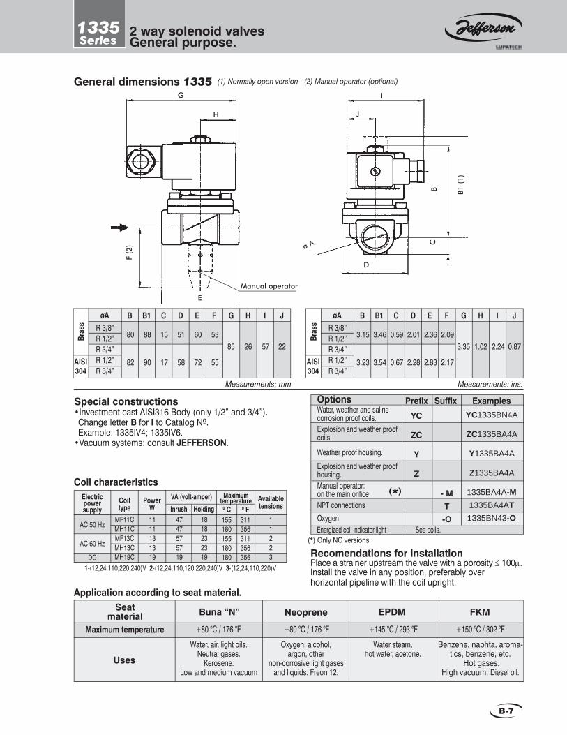
(1) Normally open version - (2) Manual operator (optional)General dimensions 1335
D
ø A CB B1
(1)
I
J
G
F (2
)
E
Manual operator
H
(*) Only NC versions
Measurements: mm
80
82
B B1øA
Bras
s
AISI304
C D ER 3/8”R 1/2”R 3/4”R 1/2”R 3/4”
F G H I
85 26
J
57 2288
90
15
17
51
58
60
72
53
55
Measurements: ins.
3.15
3.23
B B1øABr
ass
AISI304
C D ER 3/8”R 1/2”R 3/4”R 1/2”R 3/4”
F G H I
3.35 1.02
J
2.24 0.873.46
3.54
0.59
0.67
2.01
2.28
2.36
2.83
2.09
2.17
+80 °C / 176 °F +80 °C / 176 °F +145 °C / 293 °F +150 °C / 302 °F
YC
ZC
Y
Z
YC1335BN4A
ZC1335BA4A
Y1335BA4A
Z1335BA4A
1335BA4A-M1335BA4AT1335BN43-O
- MT-O
(*)
Water, weather and saline corrosion proof coils. Explosion and weather proof coils.
Weather proof housing.
Explosion and weather proof housing.Manual operator: on the main orifi ceNPT connectionsOxygenEnergized coil indicator light See coils.
Options Prefi x Examples Suffi x

B-8
2 way solenoid valvesGeneral purpose.
1342Series
Main characteristics.Normally closed or normally open.Servo-operated action.¾” to 3” BSP or NPT threaded connections.Body: Forged brass or stainless steel.Core tube SS. 304 and 316.Plunger and fi xed core: SS. 430 F.Shading coil: copper, silver or aluminium
Shape A DIN 43650 Connection encapsulated coils.IP65 and NEMA4 Protection.Options:•Energized coil indicator light.•Explosion and / or weather proof coils and housings.•Manual operator on main passage.•Manual operator on pilot orifi ce.
Applications:•Pumps. Laundry equipments.•Irrigation. Compressors. Pollution controls.•Heating with medium or high pressure steam.•Autoclaves. Industrial laundry equipments.•Spraying. Irrigation. •Air dryers. water treatment.
UnderwritersLaboratories Inc.®
CanadianStandards
Associationcanadienne denormalisation
Association
New productsHydraulic, Water
Hammer-Proof Selenoid Valve
To request a technical bulletin for models that are not included in
this catalog, please contact JEFFERSON at:
CERTIFIED QUALITY SYSTEM
Contact our manufacturing plant forin format ion on ava i lab le models
1342 Series
3/4”1”
1.1/2”2”
2.1/2”3
202638507676
51125406685
1342BA061342BA081342BA121342BA161342BA201342BA24
1.21.73.14.11918
0.79 1.021.501.973.003.00
5.91329477799
2.63.86.89.04240
Buna “N” Neoprene EPDM FKM PTFEkgCvmm ins. Kv
Maximum temp. and catalog Nº according to seat materialFlowfactor
Technical specifi cations - Brass body
Weight
Lb
1342BN061342BN081342BN121342BN161342BN201342BN24
1342BE061342BE081342BE121342BE161342BE201342BE24
1342BV061342BV081342BV121342BV161342BV201342BV24
1342BT061342BT081342BT121342BT161342BT201342BT24
3/4”1”
1.1/2”2”
2.1/2”3
202638507676
51125406685
1.21.73.14.11918
0.79 1.021.501.973.003.00
5.91329477799
2.63.86.89.04240
1342BA06INA1342BA08INA1342BA12INA1342BA16INA1342BA20INA1342BA24INA
1342BN06INA1342BN08INA1342BN12INA1342BN16INA1342BN20INA1342BN24INA
1342BE06INA1342BE08INA1342BE12INA1342BE16INA1342BE20INA1342BE24INA
1342BV06INA1342BV08INA1342BV12INA1342BV16INA1342BV20INA1342BV24INA
1342BT06INA1342BT08INA1342BT12INA1342BT16INA1342BT20INA1342BT24INA
Normally open
Normally closed
Operating pressure differential
bar0.50.5
psi7.57.5
bar0.20.2
psi33
bar1710
psi255 150
bar1510
psi225150
bar1010
psi150150
MinimumOthers seats Buna “N” seat PTFE seat Other seats
Maximum other fl uidsPTFE seatType
NCNO
*Advise: when using direct current (DC), a 25% reduction on the maximum operating pressure differential is expected
* * * *
Maximum steam
80 °C / 176 °F 80 °C / 176 °F 145 °C / 293 °F 150 °C / 302 °F 180 °C / 356 °F
ØPipeins
Ø Orifi ce

B-9
2 way solenoid valvesGeneral purpose.
1342Series
Special constructionsStainless steel body:•AISI304: change letter B for S in the catalog Nº. Example: 1342ST08.•AISI316: change letter B for I in the catalog Nº. Example: 1342IT08.
OptionsWater, weather and saline corrosion proof coils. Explosion and weather proof coils.Weather proof housing.Explosion and weather proof housing.Manual operator: on main orifi ce.Manual operator on pilot orifi ce.NPT connections
Prefi x YC
ZC
Y
Z
Examples Suffi xYC1342BA08
ZC1342BA08
Y1342BA08
Z1342BA08
1342BA08-M
1342BA08-MP
1342BA08T
- M
-MP
T Energized coil indicator light See coils.
1-(12,24,110,220,240)V 2-(12,24,110,120,220,240)V 3-(12,24,110,220)V
Coil characteristicsElectricpowersupply
Availabletensions
MaximumtemperatureCoil
typePower
WVA (volt-amper)
Inrush MF11CMH11CMF13CMH13CMH19C
1111131319
4040454519
2222272719
11223
Holding 0 C 0 F155 180 155 180 180
311356311356356
Application according to seat materialBuna “N” NeopreneSeat
material EPDM
Maximum temperature
FKM PTFE
Water, air, light oils. Neutral gases.
Kerosene, low and medium vacuum
Oxygen, alcohol, argon, other
non-corrosive light gases and liquids,
Freon 12.
Steam, hot oils,
corrosive fl uids.
Water steam, hot water, acetone.
Benzene, naphta, aromatics, etc. hot
gases,diesel oil.
Uses
Recommendations for installation.Place a strainer upstream the valve with a porosity ≤ 100µ.Mount the valve preferably over horizontal pipeline with the coil upright. The valve input pressure must always be > than the output pressure. In order to allow the normally closed or normally open valve to open, the minimum pressure indicated for each model must be respected.
General dimensions 1342 GH
I
øA
B
E
F
D
D1
Pg9
C
Manual operator(Optional)
Measurements: ins.
B CøA D D1 E F G H2.052.643.193.826.42
1.021.181.421.733.50
4.094.254.694.928.43
4.494.655.085.318.82
R 3/4”R 1”
R 1,1/2”R 2”
R 2,1/2”-3”
2.803.784.495.048.82
2.682.833.113.356.69
1.06 1.38
3.314.094.805.43
-
I
Measurements: mm
B CøA D D1 E F G H52678197
163
2630364489
104108119125214
114118129135224
R 3/4”R 1”
R 1,1/2”R 2”
R 2,1/2”-3”
7196
114128224
68727985
170
27 35
84104122138
-
I
PTFE seat not availableOnly NC versions.
**( )
**( )*( )
**( )*( )
AC 50 Hz
AC 60 Hz
DC
+80 °C / 176 °F +80 °C / 176 °F +145 °C / 293 °F +150 °C / 302 °F +180 °C / 356 °F

B-10
2 way solenoid valvesGeneral purpose.
1390Series
1390 Series
Main characteristicsNormally closed and normally open.Piston servo-operated action.Brass, stainless steel body.BSP or NPT threaded connections.Buna N seats for neutral fl uids up to 80 °C and PTFE up to 180 ºC.Encapsulated coils. Shape A DIN 43650 Connection.IP65 and NEMA4 Protection.
Options:•Energized coil indicator light.•Explosion and / or weather proof coils and housings.•Manual operator.
Applications:•Pumps, laundry equipments.•Irrigation. Compressors. Pollution control.•Heating with medium or high pressure steam.•Spraying. Irrigation. •Air dryers. Water treatment.•Autoclaves. Industrial laundry equipments.
UnderwritersLaboratories Inc.®
CanadianStandards
Associationcanadienne denormalisation
Association
CERTIFIED QUALITY SYSTEM
Contact our manufacturing plant forin format ion on ava i lab le models
Buna “N” Neoprene EPDM FKM PTFEkgCvmm ins. Kv
Maximum temp. and catalog Nº according to seat materialFlowfactor
Technical specifi cations - Brass body
1/4”3/8”1/2”
1/4”3/8” 1/2”
Weight
6912
Lb
0.801.602.35
1390BA21390BA31390BA4
1390BN21390BN31390BN4
1390BE21390BE31390BE4
1390BV21390BV31390BV4
0.700.650.90
1390BT21390BT31390BT4
0.24 0.35.47
0.941.872.75
1.61.4
2.00
0.801.602.35
1390BA2INA1390BA3INA1390BA4INA
1390BN2INA1390BN3INA1390BN4INA
1390BE2INA1390BE3INA1390BE4INA
1390BV2INA1390BV3INA1390BV4INA
0.700.650.90
6912
1390BT2INA1390BT3INA1390BT4INA
1.61.4
2.00
0.24 0.35.47
0.941.872.75
Normally closed
Normally open
bar psiType
bar psi bar
Maximum other fl uidsMinimum
Operating pressure differential Maximum steam
psiNCNO
0.10.1
1.51.5
15 10
225150
1010
150150
bar33
psi4545
PTFE seat EPDM seat
*Advise: when using direct current (DC), a 25% reduction on the maximum operating pressure differential is expected
* *
80 °C / 176 °F 80 °C / 176 °F 145 °C / 293 °F 150 °C / 302 °F 180 °C / 356 °F
ØPipeins
Ø Orifi ce

B-11
2 way solenoid valvesGeneral purpose.
1390Series
General dimensions 1390
Measurements: ins.
BøA D E F G H I
1.89
1.97
0.59
0.67
3.03
3.58
2.24
2.24
R 1/4”R 3/8” R 1/2”
0.87
0.87
3.35
3.35
1.06
1.06
JC
2.05
2.56
Special constructionsStainless steel body:•AISI304: change letter B for S in the catalog Nº. Example: 1390ST4.•AISI316: change letter B for I in the catalog Nº. Example: 1390IT4.
Measurements: mm
BøA D E F G H I
48
50
15
17
77
91
57
57
R 1/4”R 3/8” R 1/2”
22
22
85
85
27
27
JC
52
65
-
78
E
F
R 1/4”-3/8”Pg
9 DC
BI
G
H
E
F
R 1/2”
B C
D
100
(INA
)
Pg9
GH
IJ
OptionsWater, weather and saline corrosion proof coils. Explosion and weather proof coils.Weather proof housing.Explosion and weather proof housing.Manual operator: on the main orifi ceNPT connections
Prefi x YC
ZC
Y
Z
Examples Suffi xYC1390BA4
ZC1390BA4
Y1390BA4
Z1390BA4
1390BA4-M
1390BA4T
- M
T Energized coil indicator light See coils.
-
3.07
( )
Only NC versions.
Manual operator
(optional)
*
( )*
1-(12,24,110,220,240)V 2-(12,24,110,120,220,240)V 3-(12,24,110,220)V
Coil characteristicsElectricpowersupply
Availabletensions
MaximumtemperatureCoil
typePower
WVA (volt-amper)
Inrush MF11CMH11CMF13CMH13CMH19C
1111131319
4040454519
2222272719
11223
Holding155 180 155 180 180
311356311356356
Application according to seat material
Buna “N” NeopreneSeat material EPDM
Maximum temperature
FKM PTFE
Water, air, light oils. Neutral gases.
Kerosene, low and medium vacuum
Oxygen, alcohol, argon, other
non-corrosive light gases and liquids,
Freon 12.
Steam, hot oils,
corrosive fl uids.
Water steam, hot water, acetone.
Benzene, naphta, aromatics, etc., hot
gases,diesel oil.
Uses
Recommendations for installationPlace a strainer upstream the valve with a porosity ≤ 100m. Mount the valve in any position, preferably over horizontal pipeline with the coil upright. The valve input pressure must always be > than the pressure downstream from the valve. For the normally closed or normally open valve to open, the minimum pressure indicated in each model must be observed.
AC 50 Hz
AC 60 Hz
DC
0C 0F
+80 °C / 176 °F +80 °C / 176 °F +145 °C / 293 °F +150 °C / 302 °F +180 °C / 356 °F

B-12
1393Series
2 way solenoid valves.For steam and other hot fl uids.
Main characteristicsNormally closed and normally open.Direct action. No minimum differential pressure to operate.Forged brass, nickel-plated forged brass body.BSP or NPT threaded connections.Stainless steel blade type closure PTFE seats.The straight passage prevents pressure drops andturbulence caused by the fl uid’s changing direction asit is the case with conventional valves.
Options:• Explosion and weather proof housings.
1393 Series
Applications:• Autoclaves. Steam irons.• Condensation purge in air systems.• Coffee machines. Fryers.
CERTIFIED QUALITY SYSTEM
Contact our manufacturing plant forin format ion on ava i lab le models
barCvmm ins. Kv
Flowfactor
Technical specifi cations
1/4”3/8”1/2”
1/4”3/8” 1/2”
∆p maximum
8
psi
1.802.802.80
40.312.1
3.283.28
60
1.802.802.80
48 600.312.1
3.283.28
Normally open
Weight
kg Lb
Normally closed 0.830.750.77
1.81.71.7
0.830.750.77
1.81.71.7
Maximumtemperature
°C °F
180 356
180 356
Catalog Nº.
Brass Nickel plated
1393BS0821393BS0831393BS084
1393NS0821393NS0831393NS084
1393BS082NA1393BS083NA1393BS084NA
1393NS082NA1393NS083NA1393NS084NA
Important: This series is not available for DC
ØPipeins
Ø Orifi ce

B-13
1393Series
2 way solenoid valves.For steam and other hot fl uids.
Recommendations for installationPlace a strainer upstream the valve with a porosity ≤ 100µ. Mount only over horizontal pipeline with the coil upright.
1 - ( 1 2 , 2 4 , 1 1 0 , 2 2 0 , 2 4 0 ) V 2 - ( 1 2 , 2 4 , 1 1 0 , 1 2 0 , 2 2 0 , 2 4 0 ) V
Coil characteristicsElectricpowersupply
Availabletensions
MaximumtemperatureCoil
typePower
WVA (volt-amper)
Inrush M20HM20H
2020
6666
3333
12
Holding 0 C 0 F180 180
356356
General dimensions 1393H
G
C
F
E
ØA
B
D
Measurements: mm
BøA D E F G H
54R 1/4”R 3/8” R 1/2”
C
25 104 73 38 25 68
Measurements: ins.
BøA D E F G H
2.13R 1/4”R 3/8” R 1/2”
C
0.98 4.09 2.87 1.50 0.98 2.68
OptionsWeather proof housing
Explosion and weather proof housing
NPT connections
Prefi x
Y
Z
Examples Suffi xY1393BS802
Z1393BS802
1393BS802TT
AC 50 HzAC 60 Hz
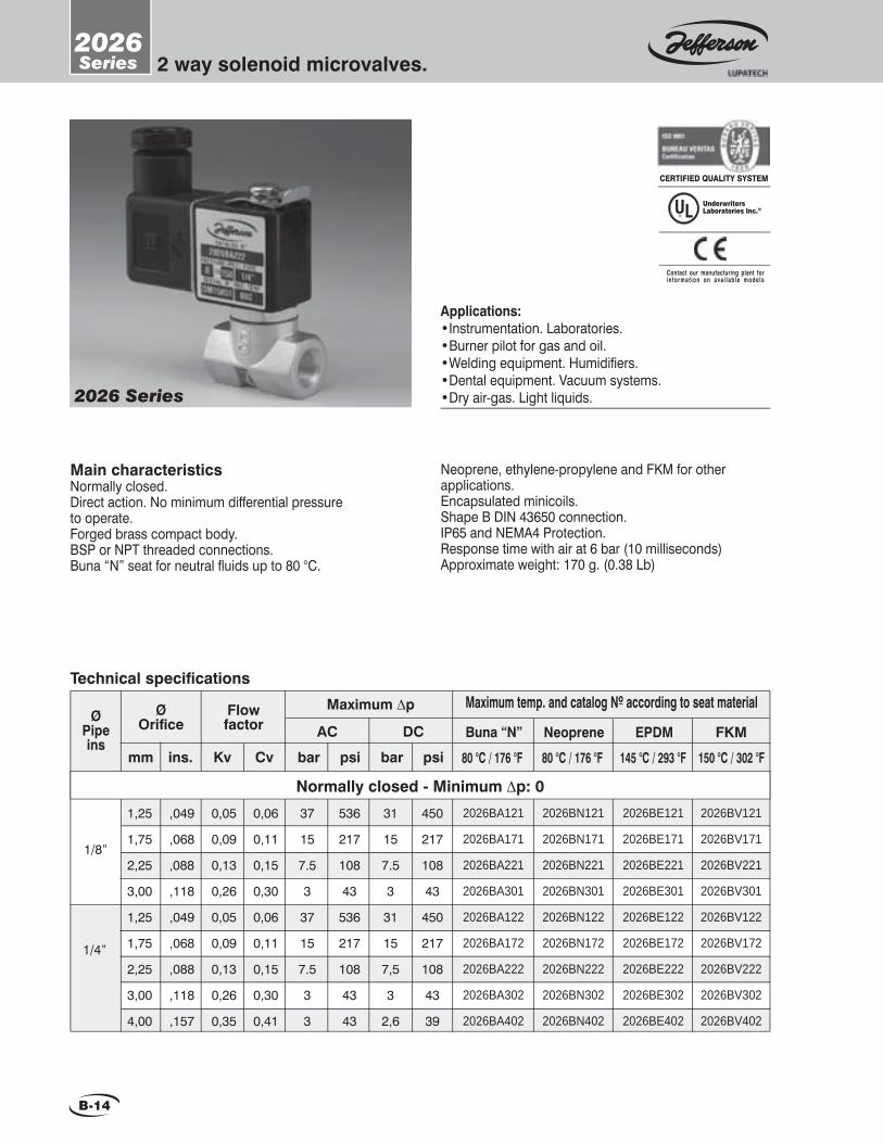
B-14
2026Series 2 way solenoid microvalves.
Main characteristicsNormally closed.Direct action. No minimum differential pressure to operate.Forged brass compact body.BSP or NPT threaded connections.Buna “N” seat for neutral fl uids up to 80 °C.
Neoprene, ethylene-propylene and FKM for other applications.Encapsulated minicoils.Shape B DIN 43650 connection.IP65 and NEMA4 Protection.Response time with air at 6 bar (10 milliseconds)Approximate weight: 170 g. (0.38 Lb)
2026 Series
Applications:•Instrumentation. Laboratories.•Burner pilot for gas and oil.•Welding equipment. Humidifi ers. •Dental equipment. Vacuum systems.•Dry air-gas. Light liquids.
CERTIFIED QUALITY SYSTEM
UnderwritersLaboratories Inc.®
Contact our manufacturing plant forin format ion on ava i lab le models
0,05
0,09
0,13
0,26
0,05
0,09
0,13
0,26
0,35
2026BA121
2026BA171
2026BA221
2026BA301
2026BA122
2026BA172
2026BA222
2026BA302
2026BA402
2026BE121
2026BE171
2026BE221
2026BE301
2026BE122
2026BE172
2026BE222
2026BE302
2026BE402
2026BV121
2026BV171
2026BV221
2026BV301
2026BV122
2026BV172
2026BV222
2026BV302
2026BV402
2026BN121
2026BN171
2026BN221
2026BN301
2026BN122
2026BN172
2026BN222
2026BN302
2026BN402
,049
,068
,088
,118
,049
,068
,088
,118
,157
Buna “N” Neoprene EPDM FKM
80 °C / 176 °F 80 °C / 176 °F 145 °C / 293 °F 150 °C / 302 °Fpsibarmm ins. Kv Cv
Maximum temp. and catalog Nº according to seat materialMaximum ∆p
1/8”
1/4”
1,25
1,75
2,25
3,00
1,25
1,75
2,25
3,00
4,00
Normally closed - Minimum ∆p: 0
psibar
AC DC
31
15
7.5
3
31
15
7,5
3
2,6
450
217
108
43
450
217
108
43
39
ØPipeins
Flow factor
Ø Orifi ce
Technical specifi cations
0,06
0,11
0,15
0,30
0,06
0,11
0,15
0,30
0,41
37
15
7.5
3
37
15
7.5
3
3
536
217
108
43
536
217
108
43
43

B-15
2026Series 2 way solenoid microvalves.
Recommendations for installationPlace a strainer upstream the valve with a porosity ≤ 100µ.Any position.Preferably over horizontal pipeline with the coil upright.
Measurements: mm
BøA D E F G32R 1/8”
R 1/4”
C18 76 61 57 14
Measurements: ins.
BøA D E F G1.26R 1/8”
R 1/4”
C0.71 2.99 2.40 2.24 0.55
Application according to seat material
Buna “N” NeopreneSeat material EPDM
Maximum temperature
FKM
Water, air, light oils, kerosene, low and medium vacuum,
neutral gases.
Oxygen, alcohol, argon, other
non-corrosive light gases and liquids,
Freon 12.
Water steam, hot water, acetone.
Benzene, naphta, aromatics, etc.
hot gases,high vacuum,
diesel oil,benzine.
Uses
F Pg9
øA
D
B
C
General dimensions 2026
E
G Mounting hole 3.5 mm (0.14 “)
OptionsNPT connections
Prefi x T
Examples Suffi x2026BA121T
Coil characteristicsElectricpowersupply
AC 50 HzAC 60 Hz
DC
Availabletensions
MaximumtemperatureCoil
typePower
WVA (volt-amper)
Inrush GF06CGF06CGF06C
666
Holding155 155 155
311311311
10.812.9
6
7.58.06
123
1-(12,24,110,220,240)V 2-(12,24,110,120,220,240)V 3-(12,24,110,220)V
+80 °C / 176 °F +80 °C / 176 °F +145 °C / 293 °F +150 °C / 302 °F
0C 0F

B-16
2036Series
2 way solenoid valves.General purpose.
2036 Series
2036 Applications:•Washing machines.•Lubricated air, hot air, dry air, etc.•Oxygen and acetylene equipments.•Spraying. Irrigation. •Air dryers. Water treatment.
New!! New!! Serie 2036VSerie 2036V
2036V Applications: Steam valve up to 10 barLaundry, dry-cleaning, etc.
2036 Main features:• Normally closed.• Piston or diaphragm servo-operated action.• Forged brass body.• BSP or NPT threaded connections.• Buna N or neoprene diaphragm with plastic core, EDPM or FKM with metal core, or brass piston with PTFE.• Shape B DIN 43650 connection encapsulated minicoils.• IP65 and NEMA4 Protection.
psiSize
bar psi bar
MaximumMinimum*Maximum steam
3/8”1/2”3/4”1”
0.2
0.3
3
4.5
15 218
bar
3
psi
45
EPDM
Operating pressure differential
bar psiPTFE
Technical specifi cations
Cvmm ins Kv
3/8”1/2”3/4”1”
13131625
2.603.605.50
9
0.500.500.63
1
2.904.206.40
10.50
kg Lb
0.3200.3200.2250.980
0.70.71.42.2
2036BE032036BE042036BE062036BE08
2036BN032036BN042036BN062036BN08
Neoprene EPDM FKM
80°C / 176°F 150°C / 302°F 145°C / 293°F2036BV032036BV042036BV062036BV08
2036BA032036BA042036BA062036BA08
Buna “N”
80°C / 176°F
ø Connect.
Maximum temp. and catalog Nº according to seat materialFlowfactor
ø Orifi ce Weight
Note: Buna N, Neoprene, EPDM y FKM: diaphragm. PTFE: piston. Only for steam.
10 145 3 45
10
-
150
-
PTFE
180 °C / 356 °F2036BT032036BT042036BT06
-
UnderwritersLaboratories Inc.®
Contact our manufacturing plant for in format ion on ava i lab le models
CERTIFIED QUALITY SYSTEM
New!!
* With PTFE rings minimum: 0.3 bar (4 psi)

B-17
2036Series
2 way solenoid valves.General purpose.
General dimensions 2036
Recommendations for installationPlace a strainer upstream the valve with a porosity ≤ 100µ.Preferably over horizontal pipeline with the coil upright.
OptionsMounting bracket
NPT connections
Prefi x -MB
T
Examples Suffi x2036BA03-MB
2036BA06T
Energized coil indicator light See coils.
Coil characteristicsElectricpowersupply
AC 50 HzAC 60 Hz
DC
Availabletensions
MaximumtemperatureCoil
typePower
WVA (volt-amper)
Inrush GF06CGF06CGF06C
666
Holding155 155 155
311311311
10.812.9
6
7.58.06
123
1-(12,24,110,220,240)V 2-(12,24,110,120,220,240)V 3-(12,24,110,220)V
B*A* D* E* F* G*2952.5
C*13 7.9 5 3.5 45.5
Measurements: mm
Measurements: ins.
B*A* D* E* F* G*1.142.07
C*0.51 0.31 0.20 0.14 1.79
Measurements: ins.
Measurements: mm
Application according to seat material
Buna “N” NeopreneSeat material EPDM
Maximum temperature
FKM
Water, air, light oils. Neutral gases. Kerosene, low and medium vacuum
Oxygen, alcohol, argon, other
non-corrosive light gases and liquids,
Freon 12.
Water steam, hot water, acetone.
Benzine, naphta, aromatics, etc.
hot gases,high vacuum,
diesel oil.
Uses
C
B
D E
øA
B
E
A*
E * B *D*
F* G*
C* C*
Fixing plate (optional)
Measurements: mm
BøA D ECR 3/8” R 1/2”R 3/4”R 1”
95
103115
13
1721
45
5272
64
7399
Measurements: ins.
BøA D ECR 3/8” R 1/2”R 3/4”R 1”
3.74
4.064.53
0.51
0.670.83
1.77
2.052.83
2.52
2.863.90
General dimensions 2036V BøA D ECR 3/8” R 1/2”R 3/4”
100,5
115
13
17
45
52
64
73
BøA D ECR 3/8” R 1/2”R 3/4”
3.96
4.53
0.51
0.67
1.77
2.05
2.52
2.86
Water steam.
PTFE
C
B
D E
øA
+80 °C / 176 °F +80 °C / 176 °F +145 °C / 293 °F +150 °C / 302 °F +180 °C / 356 °F
0 C 0 F

B-18
1359Series
“Y” strainerfor general purpose.
Main characteristicsGray cast body.Basket type fi ltering element with stainless steel double mesh.Particle retention capacity from 100 microns.Its design features guarantee 100% fi ltration of the product.Flanged cover with drainage connection.
1359 Series
OptionsNPT connections
Example Suffi x1359BS4TT
Applications:•Strainers must be used wherever it is essential that the fl uid fl owing through pipe lines be maintained free of foreign solid matter, to assure the correct operation of the solenoid valve.
General dimensions 1359
Measurements: mm
B CA D(ø)607895
121165
1618213239
1/2”3/4” 1”
1.1/2” 2”
80100120150180
Measurements: ins.
B CA D(ø)2.363.073.744.766.49
0.630.700.821.261.53
1/2”3/4” 1”
1.1/2” 2”
3.153.934.725.907.08
Technical specifi cations
barCvKv
Flowfactor ∆p Maximum
psi
Weight
kg Lb
Maximumtemp.
°C °F Catalog Nº.
1/23/41
1.1/22
Iron body (1)612194065
0.51
1.63
5.2
1359FS041359FS061359FS081359FS121359FS16
10 180150 356
1.12.23.56.611.5
714224776
øPipe ins.
A
øD
CB
øD
Drainage plug

C-1
1312 - 2012 Series
1330 - 2030Series
1312 - 2012 1330 2030
1332 Series
1332
1356 Series
1356
1388 Series
1388
2088
2 Way Solenoid Valves for CombustionUse
C-10 / C-11
C-12 / C-13
C-14 / C-15
C-16 / C-17 C-18 / C-19
2088 Series
C-20 / C-21 C-22
Combustion Solenoid valves.For liquid fuel and combustible gases.
2 way solenoid valves.For fuel oil.
2 way valves.For fuel gas and other gases.
Free handle manualreset safety valve.
2 way solenoid valvesfor fuel oil, gas-oil and mixtures thereof.
Solenoid valveswith slow opening and quick shutoff for natural gas and other gases.
Solenoid valveswith slow opening and quick shutoff for natural gas and other gases.
Thermoelectric safety valves.
C-2 / C-3 C-4 / C-5 C-6 /
C-7
C-8 / C-9
Pages
V171 SeriesC-23 / C-24
V171
New products NEW SOLENOID VALVE MODELS• Intrinsically Safe.• Low Power.• Slow-Opening for Gas - 1/2” & 3/4”.• ATEX Explosion-Proof Coils.
To request a technical bulletin for models that are not included in this catalog, please contact JEFFERSON at:

C-2
Jefferson provides solenoid valves specially designed forcombustion, for bothliquid andgaseous fuels.
Solenoid valves for liquid fuels1312 - 2012 and 1356 Series are direct acting and are applied particularly for the control of all fuel oil grades, both light and heavy, for temperatures up to 180 °C (356 °F) and pressure up to 21 bar (300 psi).
Typical circuit of a fuel oil burner with mechanical pressure atomizer, preheated up to more than 100 °C, with a recirculation valve and an atomization cartridge cleaning valve.
Pump
Air,steam,etc.
Burner
Fuel oil
N.C. Solenoid Valve(atomization cartridge
cleaning, etc.)
RetentionValve
Relief valve
Preheater
N.C. Solenoid ValveCombustion
N.D. Solenoid Valve(recirculation)
They may also be used for LPG; heavy oil, gas or steam. Series 2026 and 1327 described in General Purpose section, are also applied to light liquid fuel burners, such as gas-oil or LPG.
Combustion

C-3
Combustion
For Fuel oil Nº 6 (212 °F) in Lb/hourFor Fuel oil Nº 2 (68 °C) in gal/min
∆ppsi
Nº 6
1312 / 2012 Series1356 Series
1
2
3
4
5
10
20
25
50
100
150
77
108
133
153
171
242
343
383
542
766
939
10
14
17
20
22
31
45
50
70
100
122
Nº 2 Nº 6 Nº 2 Nº 6 Nº 2 Nº 6 Nº 2 Nº 6 Nº 2 Nº 6 Nº 2
0.15 0.7 0.46 0.7 1.6 2.9
354
500
613
707
791
1119
1582
1769
2501
3537
4332
46
65
80
92
103
145
206
230
325
460
563
230
325
398
460
514
727
1028
1150
1626
2299
2816
30
42
52
60
67
94
134
149
211
299
366
354
500
613
707
791
1119
1582
1769
2501
3537
4332
46
65
80
92
103
145
206
230
325
460
563
825
1167
1429
1651
1845
2610
3691
4127
5836
8253
10108
107
152
186
214
240
339
480
536
758
1072
1313
1474
2084
2553
2948
3295
4660
6591
7369
10421
14738
18050
191
271
332
383
428
606
856
957
1354
1915
2345
Flow factor Cv Flow factor Cv
Flow chartsFor Fuel oil (100 °C) in kg/hourFor Gas-oil (20 °C) in liters/hour
∆p bar
Fuel oil
1312 - 2012 Series1356 Series
0.1
0.2
0.3
0.4
0.5
0.7
1
2
3
5
10
41
58
71
82
91
108
129
183
224
289
409
45
63
78
90
100
119
142
201
246
317
449
Gas-oil Fuel oil Gas-oil Fuel oil Gas-oil Fuel oil Gas-oil Fuel oil Gas-oil Fuel oil Gas-oil
0.13 0.6 0.39 0.6 1.4 2.5
189
267
327
378
422
499
597
844
1034
1335
1888
207
293
359
414
463
548
655
926
1134
1464
2070
123
174
213
245
274
325
388
549
672
868
1227
135
190
233
269
301
356
426
602
737
952
1346
189
267
327
378
422
499
597
844
1034
1335
1888
207
293
359
414
463
548
655
926
1134
1464
2070
440
623
763
881
985
1165
1393
1970
2413
3115
4405
483
683
837
966
1080
1278
1528
2160
2646
3416
4830
787
1112
1362
1573
1759
2081
2487
3518
4308
5562
7866
863
1220
1494
1725
1929
2282
2728
3858
4725
6099
8626
Flow factor Kv Flow factor Kv

C-4
Combustion
Solenoid valves for combustible gases1330 / 2030, 1332, 1388 and 2088 Series valves are especially designed to comply with the Resolutions, Regulations and Recommendations for the use of Natural Gas in Industrial Installations. They may be used with other gases, such as GLP, propane, manufactured gas, etc., as well as with air or any other noncombustible neutral gas.Maximum operating pressure for normally closed 1330/2030 series diaphragm valves, when applied as safety valves in natural gas burners, is 0.160 kg/cm2. For normally open valves, it’s 0.5 kg/cm2 with regular diaphragm and 2 kg/cm2 with reinforced diaphragm.1330 / 2030 Series Normally Closed diaphragm valves are optionally provided with adjustable slow openings up to 10 sec.
1388 series valves include a system that allows them to open in two stages, the fi rst of which is quick and with adjustable opening percentage, and the second is time adjustable up to > 20 seconds.1330 / 2030, 1332, 1388 and 2088 Series areoptionally provided with microcontacts for proof of closed valve. 2088 Series is provided with a power-rectifi er-controller that makes it possible for the valve to open at max. coil power, and after 90 sec. to come down to 16% of nominal value, that is, starting at 50 W and down to 8 W after 90 sec. The benefi ts over conventional systems are, safe opening, low power consumption, low working temperature and longer coil life.
Automatic shutoff valve train for Natural Gas boiler burners according to current Resolutions for industrial installations
TC: Thermal Charge: 1 kwh = 860 kcal./h = 3,412 btu/h; Ct: Maximum Closing Time in seconds; Mot: Minimum opening time in seconds; MCVV: micro-contact for closed valve verifi cation.
Requirements Boiler maximum thermal chargeSemiautomatic and manualAutomatic
One automatic shutoffvalve.
Tc< 5 sec.
Two automatic shutoff valves or one automatic shut-off valve with microcontact for
closed valve verifi cation (MCVV)
Tc: < 1 sec.Two automatic shutoff valves, one with MCVV.
Valve upstream of the train:
Mot = 10 sec.Both Tc: < 1 sec.
Two automatic shutoff valves with a venting N.O. valve in between.
Mot: 10 sec.Tc < 1 sec.
Two automatic shutoff valves, one with MCVV and one venting N.O.
valve in between.Mot: 20 sec.Tc < 1 sec.
CT < 360 kwh = = 309,600 kcal./h == 1,228,320 btu/h
CT < 720 kwh = = 619,200 kcal./h == 2,456,640 btu/h
without pilotCT < 600 kwh =
= 516,000 kcal./h == 2,047,200 btu/h
CT < 1,800 kwh = = 1,548,000 kcal./h
pilot burnersCT < 60 kwh =
= 51,600 kcal./h == 204,720 btu/h(no need for Mot)
CT < 12,000 kwh = = 10,320,000 kcal./h =
= 40,944,000 btu/h
CT > 12,000 kwh ==10,320,000 kcal./h =
= 40,944,000 btu/h
CT < 600 kwh = = 516,000 kcal./h == 2,047,200 btu/h
CT < 1,200 kwh = = 1,032,000 kcal./h =
= 4,094,400 btu/h
CT < 3,600 kwh = = 3,096,000 kcal./h == 12,283,200 btu/h
pilot burnersCT < 60 kwh =
= 51,600 kcal./h == 204,720 btu/h(no need for Mot)
CT < 12,000 kwh = = 10,320,000 kcal./h =
= 40,944,000 btu/h
CT > 12,000 kwh = = 10,320,000 kcal./h =
= 40,944,000 btu/h
For equipment wiith a thermal charge greater than 30,000 kwh and multiple burners, an automatic shutoff valve independent from the burner system shall be provided. (See manual reset valves).
Diagrams

C-5
Combustion
Tandem valves for a multiple fi re-outlet gas combustion system.1 Main manual shutoff valve.2 Gas strainer.3 Main gas pressure regulator.4 Venting safety valve.5 Pressure switch for minimum gas pressure.6 Series standard closed manual reset valve.7 Venting standard open solenoid valve.8 Manual valve with microcontact verifi cation.9 Pressure switch for maximum gas pressure.10 Manual shutoff valve for leakage test.11 Manual shutoff valve.12 Firepower regulation device.13 Burner.14 Pilot gas pressure regulator.15 Pilot solenoid valve.16 Ventilator.17 Pressure switch for minimum air pressure.
1 Main manual shutoff valve.2 Gas strainer.3 Main gas pressure regulator.4 Venting safety valve.5 Pressure switch for minimum gas pressure.6a 1º Series standard closed solenoid valve.6b 2º Series standard closed solenoid valve.7 Venting standard open solenoid valve.8 Pressure switch for maximum gas pressure.9 Loss testing manual valve.10 Firepower regulation device.11 Burner.12 Pilot gas pressure regulator.13 pilot solenoid valve.14 Manual valve for leakage.15 Pressure switch for minimum air pressure.
Stove Burner Requirements: They are similar to those indicated for boilers. If there are no fl ame control devices available, an automatic shutoff and manual reset valve shall be installed.Manual systems: The combustion equipment includes at least two automatic shutoff valves, one of which is a manual reset valve.
Applications. Tandem valves for an automatic gas burner up to 12,000 kw.
Kv calculation for two valves or more
StrainersAppliances which are not for domestic use must have strainers or dust separators immediately after the (ma-nual) blocking valve. Said strainers shall retain 100% of the solid particles from 50µ.
Gas supply
Pilot line
12 4 13 14 15 11
1 2 3 4 5 6a 7 6b 8 9 10
Main line
Mainline
Pilotline
Gassupply
1 2 3 4 86 7 6 9 105
11 12 13
14 4 15 10
16 17
topilots
-2 equal valves in series. Kvt = Kv1 x 0.7
- 2 or more, equal valves or with different sizes in series.(1/Kvt )
2 = (1/Kv1 )2 + (1/Kv2 )
2 +. . . + (1/Kvn )2
- 2 or more equal valves or with different sizes in parallel.
Kvt = Kv1 + Kv2 + .. . + Kvn
Kvt: Kv equivalent to a solenoid valve that replaces them.
Cv calculation for two valves or more
-2 equal valves in series. Cvt = Cv1 x 0.7
- 2 or more, equal valves or with different sizes in series.(1/Cvt )
2 = (1/Cv1 )2 + (1/Cv2 )
2 +. . . + (1/Cvn )2
- 2 or more equal valves or with different sizes in parallel.
Cvt = Cv1 + Cv2 + .. . + CvnCvt: Cv equivalent to a solenoid valve that replaces them.
13 pilot solenoid valve.

C-6
Combustion
Calculation base: Relative density 0.65Fluid temperature: 25 °CKv=1
Application examplesDataFluid: Natural Gas density 0.60Flow: 120 Nm3/hInput pressure: 500 mm w.c.Admissible pressure drop through the valve: 15%Unknown: Kv.
Procedure1º) Flow / correction factor = 120 / 1.04 = 1152º) Search for value at intersection P1 = 500 mm w.c. and ∆p = 60 mm w.c. in the fl ow chart: value found: 2.833º) Corrected fl ow / value found = Kv: 115 / 2.83 = 40.6For 2030 Series the most approximate value is: 2030LA16 Kv = 43.For 1388 Series the most approximate value is: 1388LA16D Kv = 45
Pressure drop for kv = 451) Corrected fl ow / Kv: 115 / 45 = 2.552) Search for the closest value for P1 = 500 mm w.c. in the table, value found: in ∆p 40 value: 2.323) ∆p calculation: (2.55 / 2.32)2 x 40 = 48 mm w.c.
Pressure drop for Kv = 431) Corrected fl ow / Kv: 115 / 43 = 2.67
2) Search for the closest value for P1 = 500 mm w.c. in the table value found: in ∆p 60 value: 2.833) ∆p calculation: (2.67 / 2.83)2 x 60 = 53 mm w.c. Calculation for two valves in series with the same data:1) Corrected fl ow: 120 / 1.04 = 1152) Search for a value for p 60 or ∆p 100. We chose ∆p 100 = 3.65.3) Kv = 115 / 3.65 = 31.5 (2 valves Kv) Kv for one valve: 31.5 / 0.7 = 45.4) We must look for a valve with Kv greater than 45 to bring ∆p 100 down to < 75 mm w.c. (according to data shown)
2030 Series has no valve greater than 43, so it can only be possible in the 1388 Series: we choose catalog number 1388LA20: Kv = 65 Corrected Kv: 65 x 0.707 = 46
Pressure drop for corrected Kv = 461) Corrected fl ow / Kv: 115 / 46 = 2.52) Search for P1 = 500 mm w.c. line in the table the ∆p with the closest value: 2.83 for ∆p = 60.3) ∆p calculation: (2.5 / 2.83)2 x 60 = 47 mm w.c.
This 47 mm w.c. value belongs to the pressure drop through both valves
Correction factor for density
Relative densityCorrection factor
0.621.02
0.651.00
1.000.81
1.200.74
1.500.66
0.601.04
Flow chart for Natural Gas or other gases. Nm3/h
P1= Gauge pressure at the valve inlet in mm w.c.
P120
Pressure drop through the valve in mm w.c.
1.611.621.621.641.651.681.701.721.751.821.891.962.092.262.532.77
2.272.282.292.322.342.372.402.432.482.582.672.772.953.203.583.92
40 60 100 150 200 300 500 700 10003.583.603.623.653.693.743.793.843.904.074.224.374.655.055.656.19
4.404.424.464.504.574.634.694.774.975.165.345.696.186.917.57
5.065.095.145.195.265.335.415.505.735.956.166.567.127.978.74
6.206.266.326.416.506.596.716.997.267.528.018.709.7410.69
8.008.088.208.328.438.588.959.309.6410.2811.1812.5313.75
9.479.619.759.8910.0710.5010.9211.3312.0913.1614.7616.21
11.3211.4911.6511.8712.4012.9113.3914.3215.6017.5419.28
1500
13.9314.2114.8715.5016.1117.2618.8621.2523.41
10020030050070010001300160020003000400050007000100001500020000
2.782.792.812.832.862.902.942.983.033.153.273.393.613.924.384.80

C-7
combustion
calculation base: relative density 0.65fl uid temperature: 77 °fCv=1
application examplesDataFluid: Natural Gas density 0.60Flow: 4,300 SCFHInput pressure: 20” w.c.Admissible pressure drop through the valve: 15%Unknown: Cv.
Procedure1º) Flow / correction factor = 4,300 / 1.04 = 4,1352º) Search for value at intersection P1 = 20” w.c. and ∆p = 3” w.c. in the fl ow chart: value found: 97.5.3º) Corrected fl ow / value found = Cv: 4,135 / 97.5 = 42.4For 2030 Series the most approximate value is: 2030LA16 Cv = 50.For 1388 Series the most approximate value is: 1388LA16D Cv = 57.
Pressure drop for Cv = 501) Corrected fl ow / Cv: 4,135 / 50 = 82.72) Search for the closest value for P1 = 20” w.c. in the table value found: in ∆p 2” value: 79.73) ∆p calculation: (82.7 / 79.7)2 x 2 = 2.15” w.c.
Pressure drop for Cv = 571) Corrected fl ow / Cv: 4,135 / 57 = 72.54
2) Search for the closest value for P1 = 20” w.c. in the table, value found: in ∆p 2” value: 79.73) ∆p calculation: (72.54 / 79.7)2 x 2 = 1.66” w.c.
Calculation for two valves in series with the same data:1) Corrected fl ow: 4.300 / 1.04 = 4.1352) Search for a value for ∆p 2” or ∆p 3”. We chose ∆p 3” = 97.5.3) Cv = 4,135 / 97.5 = 42.4 (2 valves Cv) Cv for one valve: 42.4 / 0.707 = 60.4) We must look for a valve with Cv greater than 60 to bring ∆p 3” down to < 2” w.c. (according to data shown).
2030 Series has no valve greater than 50, so it can only be possible in the 1388 Series: we choose catalog number 1388LA20: Cv = 76 Corrected Cv: 76 x 0.707 = 54
Pressure drop for corrected Cv = 541) Corrected fl ow / Cv: 4,135 / 54 = 76.62) Search for P1 = 20” w.c. line in the table the ∆p with the closest value: 79.7 for ∆p = 2”.3) ∆p calculation: (79.7 / 76.6)2 x 2 = 2.19” w.c.
This 2.19” w.c. value belongs to the pressure drop through both valves
correction factor for density relative densitycorrection factor
0.621.02
0.651.00
1.000.81
1.200.74
1.500.66
0.601.04
fl ow chart for natural gas or other gases scfh
p1= gauge pressure at the valve inlet in inches w.c. 1 psi = 27,68 i.w.c.
p1pressure drop through the valve in inches w.c.
1 55.255.355.455.756.457.157.758.459.961.563.064.467.370.077.686.7
278.078.278.278.779.780.681.582.484.786.889.091.095.198.9109.6122.5
4
110.3110.4111.1112.4113.7115.0116.3119.5122.6125.6128.5134.2139.7154.9173.1
6
135.7137.3139.0140.6142.1146.0149.8153.5157.1164.1170.8189.4211.8
8
156.3158.2160.1161.9163.8168.3172.6176.9181.1189.2196.9218.5244.3
12
192.8195.1197.4199.7205.2210.6215.9221.0230.9240.4266.9298.6
20
246.5249.5252.5255.5262.7269.7276.5283.2296.1308.4342.8383.9
30
301.9305.6309.3318.2326.9335.3343.6359.5374.8417.2467.8
40
348.7352.9363.3373.5383.3393.0411.5429.3478.6537.4
60
416.4421.7434.8447.5459.8471.9495.0517.2578.5651.3
3
95.695.796.397.598.699.7100.8103.6106.3108.9111.4116.3121.0134.2150.0
245102030405075100125150200250400600

C-8
2 way solenoid valvesfor fuel oil.
1312 - 2012Series
Main characteristicsNormally closed and normally open.Lever activated direct acting. No minimum differential pressure to operate.Body: bronze, stainless steel, etc.Stainless steel needle type seats.Class H coils coated with glass fi bre and insulating impregnation. Output cables for splicing.Interior use housing with an outlet for electrical connector.
Options:• Explosion and / or weather proof housings. Suitable for heavy fl uids, such as fuel-oil, heavy oils, steam and corrosive fl uids.
1312 / 2012 Series
Applications:• Burners for fuel oil (preheated or not) and its mixtures, gas-oil, etc., with mechanical pressure atomizer, rotating cup, compressed air, steam, etc.• It may be used with heavy fl uids, steam and corrosive fl uids.
CERTIFIED QUALITY SYSTEM
barCvmm ins. Kv
Flowfactor
Technical specifi cations
1/2”
3/4”
1”
∆p maximum
5
8
11
psi
Normally open
Normally closed
155 311
Catalog Nº.
Brass AISI 304
2012BS404NA2012BS406NA2012BS506NA2012BS408NA2012BS508NA
1312SS404NA1312SS406NA1312SS506NA1312SS408NA1312SS508NA
0.60
1.40
2.50
0.7
1.6
2.9
21
12
6
300
180
90
0.20
0.31
0.43
1/2”
3/4”
1”
4
545
155 311
0.16
0.200.160.20
0.39
0.600.390.60
0.46
0.70.460.7
15
121512
225
180225180
MaximumTemp.
°C °F
2012BS5042012BS5062012BS8061312BS8081312BSB08
1312SS5041312SS5061312SS8061312SS8081312SSB08
*Advise: when using direct current (DC), a 25% reduction on the maximum operating pressure differential is expected
*
3.4
3.6
3.8
7.5
7.9
8.4
Weight
kg Lb
3.4
3.6
3.8
7.5
7.9
8.4
ØPiperins.
Ø orifi ce
(*) For steam at 10 bar

C-9
2 way solenoid valvesfor fuel oil.
1312 - 2012Series
General dimensions 1312 - 2012
Recommendations for installationMount the valve only over horizontal pipeline with the coil upright.
OptionsWeather proof housingExplosion and weather proof housingNPT connections
Prefi x Y
Z
Examples Suffi x
T
Measurements: mm
BøA D E FR 1/2”R 3/4” R 1”
C
139
147
22
30
140
147
98
106
95
96
G øH øI
95 99 3/4”NF
Measurements: ins.
BøA D E FR 1/2”R 3/4” R 1”
C
5.47
5.79
0.87
1.18
5.51
5.79
3.86
4.17
3.74
3.78
G øH øI
3.74 3.90 3/4”NF
1-(12,24,110,220,240)V 2-(12,24,110,120,220,240)V 3-(12,24,110,220)V
Coil characteristicsElectricpowersupply
AC 50 Hz
AC 60 Hz
D/C
Availabletensions
MaximumtemperatureCoil
typePower
WVA (volt-amper)
Inrush SH46CS46H(*)SH46CS46H(*)SH48CS48H(*)
464646464848
2772772862864848
1041041031034848
112233
Holding 0 C 0 F155 180 155 180 155180
311356311356311356
Y2012BS504
Z2012BS506
2012BS504T
(*) For steam at 10 bar

C-10
1330 - 2030Series 2 way solenoid valves
for fuel gas and other gases.
1330 Series 2030 SeriesMain characteristicsNormally closed and normally open. Direct acting or pilot operated versions. Injected aluminium body. Stainless steel or aluminium die-cast bonnet.
BSP or NPT threaded connections. Buna “N” seats and dia-phragm. Encapsulated coil. DIN 43650 Connection. IP65 and NEMA 4 Protection. Quick or slow opening adjustable up to 10 sec. Closure in less than 1 second. Optional: microcontact for closed valve verifi cation.
CatalogNO
Cvmm ins. Kv
Flowfactor
Technical specifi cations
1/21/23/41
1 1/4
11 1/2
2
818183232
0.3150.710.711.261.26
1.73.44.21012
24.04.91214
kg
Weight
LbbarMaximum
psibarMinimum
psi
Pressure differential
0 0
10.20.20.050.05
1533
0.750.75
0.50.50.51
0.9
1.11.11.22.21.9
1330LA01330LA041330LA062030LA082030LA10
264851
1.021.892.00
123543
144150
0.001 0.015 0.2 31
1.81.6
2.24.03.5
1330LA082030LA122030LA16
11 1/2
2
264851
1.021.892.00
123543
144150
0.001 0.015 0.2 31.091.881.66
2.44.23.7
1330LA08L2030LA12L2030LA16L
11 1/2
2
264851
1.021.892.00
123543
144150
0.001 0.015 0.2 31
1.81.6
2.24.03.5
1330LA08NA2030LA12NA2030LA16NA
1/21/23/4
81818
0.3150.710.71
1.73.44.2
24.04.9
0
0
1
0.2
15
3
0.60.60.6
1.31.31.3
1330LA0INA1330LA04INA1330LA06INA
11 1/2
2
264545
1.021.892.00
123441
144048
0.01 0.15 2 301
1.81.6
2.24.03.5
1330LAR082030LAR122030LAR16
11 1/2
2
264545
1.021.892.00
123440
144048
0.01 0.15 3021
1.81.6
2.24.03.5
1330LAR08NA2030LAR12NA2030LAR16NA
Normally closed - Direct acting
Normally open - Pilot operated - Reinforced diaphragm
Normally open - Pilot operated
Normally open - Direct acting
Normally closed - Pilot operated - Reinforced diaphragm
Normally closed - Pilot operated - Slow opening
Normally closed - Pilot operated - Quick open
0
0
UnderwritersLaboratories Inc.®
Contact our manufacturing plant for in format ion on ava i lab le modelsCERTIFIED QUALITY SYSTEM
ØPiperins.
Ø orifi ce
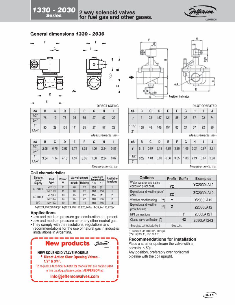
C-11
1330 - 2030Series 2 way solenoid valves
for fuel gas and other gases.
General dimensions 1330 - 2030
Measurements: mm
Measurements: ins.
DIRECT ACTINGBøA D E
1/2”3/4” 1”
1,1/4”
C
75
90
19
29
75
105
95
111
F G H I
85
85
27
27
57
57
22
22
BøA D E1/2”3/4” 1”
1,1/4”
C
2.95
3.54
0.75
1.14
2.95
4.13
3.74
4.37
F G H I
3.35
3.35
1.06
1.06
2.24
2.24
0.87
0.87
Measurements: mm
PILOT OPERATEDBøA D E
1”
1 1/2”2”
C
131
158
22
46
157
148
124
154
F G H I
85
85
27
27
57
57
22
22
J
74
98
Measurements: ins.
BøA D EC
5.16
6.22
0.87
1.81
6.18
5.83
4.88
6.06
F G H I
3.35
3.35
1.06
1.06
2.24
2.24
0.87
0.87
J
2.91
3.86
1”
1 1/2”2”
Position indicator
Recommendations for installationPlace a strainer upstream the valve with aporosity ≤ 50µ. Any position, preferably over horizontal pipeline with the coil upright.
Applications•Low and medium pressure gas combustion equipment.•Low and medium pressure air or any other neutral gas.•They comply with the resolutions, regulations and recommendations for the use of natural gas in industrial installations in Argentina.
Options Examples
Energized coil indicator light See coils.
1-(12,24,110,220,240)V 2-(12,24,110,120,220,240)V 3-(12,24,110,220)V
Coil characteristicsElectricpowersupply
AC 50 Hz
AC 60 Hz
D/C
Availabletensions
MaximumtemperatureCoil
typePower
WVA (volt-amper)
Inrush MF11CMH11CMF13CMH13CMH19C
1111131319
4040454519
2222272719
11223
Holding 0 C 0 F155 180 155 180 180
311356311356356
(*) Minimum dp 0.005 bar - 0.075 psi(**) Only for 1”, 11/2” and 2”
Water, weather and saline corrosion proof coils. Explosion and weather proof coils.Weather proof housingExplosion and weather proof housing.NPT connectionsClosed valve verifi cation (*)
YC2030LA12
ZC2030LA12
Y2030LA12
Z2030LA12
2030LA12T2030LA12-I2
Prefi x Suffi x
YC
ZCY
Z
T-I2
(**)
(**)
New products NEW SOLENOID VALVE MODELS
• Direct Action Slow Opening Valves - 1/2” & 3/4”.
To request a technical bulletin for models that are not included in this catalog, please contact JEFFERSON at:

C-12
Free handle manualreset safety valve.
1332Series
Main characteristicsNormally closed.Direct acting. No minimum differential pressure to operate.“Free handle” system, i.e., it closes automatically when current is cut off and opens manually when the electric signal is on.Injected or cast aluminium body.DIN 43650 Connection encapsulated coils.Acryl-nitryl seat.IP65 and NEMA 4 Protection.Closed or open valve viewer.
360º Rotating housing.Response time < 50 milliseconds.
Options:• Energized coil indicator light.• Weather proof coils and housings.• Explosion and / or weather proof coils and housings.• Closed valve verifi cation
1332 Series
Applications•Shutoff security systems that work with temperature limits, pressure, lack of fl ame, level, etc., in boiler com-bustion systems.•Combustion equipment with charges over 30,000 Kw/h and multiple burners.•Burners for automatic and semiautomatic furnaces.
CERTIFIED QUALITY SYSTEM
Technical specifi cations
BarCvmm ins. Kv
Flowfactor
1”1.1/4”1.1/2”
2”2 1/2”
3”
∆p Maximum
263248517676
Psi
132230556076
3
2
1
Weight
Kg Lb
MaximumTemp.
°C °F
80 1332LA081332LA101332LA121332LA161332LA201332LA24
2.3
3.33.16.26.0
1.021.261.892.003.003.00
152635647089
45
30
15
5.1
7.36.813.713.2
176
ØPipeins.
Ø Orifi ce
Catalog Nº.

C-13
Free handle manualreset safety valve.
1332Series
General dimensions 1332
Special constructions• It closes automatically as soon as it receives the electric signal. It opens manually and it is reset only when the electric signal is off.• Normally open.
Recommendations for installationPlace a strainer upstream the valve with aporosity ≤ 50 µ. Preferably over horizontal pipeline with the coil upright.
J K
I
E
F
G
B
øA
Pg9
L
CD
H
Measurements: mm.
BøA D E F G124
154
163
1”1.1/2”
2”2.1/2”
3”
C133
157
190
87
76
135
79
68
112
157
146
224
183
173
-
H104
128
162
I J K L39
39
39
190
190
190
190
190
190
90
90
90
Measurements: ins.
BøA D E F G4.88
6.6
6.42
1”1.1/2”
2”2.1/2”
3”
C5.24
6.18
7.48
3.43
2.99
5.31
3.11
2.68
4.41
6.18
0.23
8.82
7.20
6.81
-
H4.09
5.04
6.38
I J K L1.54
1.54
1.54
7.48
7.48
7.48
7.48
7.48
7.48
3.54
3.54
3.54
1-(12,24,110,220,240)V 2-(12,24,110,120,220,240)V 3-(12,24,110,220)V
Coil characteristicsElectricpowersupply
AC 50 Hz
AC 60 Hz
D/C
Availabletensions
MaximumtemperatureCoil
typePower
WVA (volt-amper)
Inrush MF11CMH11CMF13CMH13CMH19C
1111131319
4040454519
2222272719
11223
Holding 0 C 0 F155 180 155 180 180
311356311356356
OptionsWater, weather and saline corrosion proof coils. Explosion and weather proof coils.Weather proof housing.Explosion and weather proof housing.NPT connectionsClosed valve verifi cation
Prefi x YC
ZC
Y
Z
Examples Suffi x
YC1332LA12
ZC1332LA12Y1332LA12
Z1332LA12
1332LA12T1332LA12-I
T-I
Energized coil indicator light See coils.

C-14
1356Series 2 way solenoid valves
for fuel oil, gas-oil and mixtures thereof.
1356 “S” Series1356 “T” Series
Main characteristicsNormally closed.Direct acting. No minimum differential pressure to operate.Body: bronze, stainless steel, etc..BSP or NPT threaded connections.Stainless steel type closure (s).
PTFE seat closure (t).Class H coil coated with glass fi bre and isolating impregnation. Output cables for splicing (s version).Encapsulated coil. Shape A DIN 43650 connection (t version).Internal use housing with an outlet for electric connector (s version).
Options:• Explosion and weather proof coils and housings.• It may be used for heavy fl uids such as fuel oil, heavy oils, steam and corrosive fl uids.
Applications• Burners for fuel oil (preheated or not) and its mixtures, gas-oil, etc., with mechanical pressure atomizer, rotating cup, compressed air, steam, etc.• Heavy fl uids, steam, corrosive fl uids
CatalogNO
Cvmm ins. Kv
Flowfactor
Technical specifi cations
kg
Weight
LbbarMaximum
psibarMinimum
psi
Operating pressure differential
0202010
300300150
Power W
18
Version
TTS
1650 Hz 60 Hz
46
ØPipeins.
Ø Orifi ce
3/8”1/2”1/2”
2.52.55
0.0880.0880.197
0.170.170.60
0.200.200.70
0.720.683.10
1.61.56.8
1356BT31356BT4
1356BS4-48

C-15
1356Series
2 way solenoid valvesfor fuel oil, gas-oil and mixtures thereof.
General dimensions 1356 (t) - 1356 (s)B
C
ED
ED
C
G
F
Pg9
ø F
3/4” NF
G
øA
Version “T”
Version “S”
Recommendations for installation• Place a strainer upstream the valve.• “T” version: Installation: any position. Preferably over horizontal pipeline with the coil upright.• “S” version: Installation: only over horizontal pipeline with the coil upright.
øA
B
(*) For Steam. 1-(12,24,110,220,240)V 2-(12,24,110,120,220,240)V
Coil characteristicsElectricpowersupply
AC 50 Hz
AC 60 Hz
AC 50 Hz
AC 60 Hz
Availabletensions
MaximumtemperatureCoil
typePower
WVA (volt-amper)
Inrush MH18CM18H(*)MH16CM16H(*)SH46CS46H(*)SH46CS46H(*)
1818161646464646
61614848
277277286286
39392929
104104103103
11221122
Holding 0 C 0 F155 180 155 180 155180155180
311356311356311356311356
Version
T
S
1356 “S”
Measurements: mm
BVersion D E F GS
CøAR1/2” 95 73 24 142 99 98
Measurements: ins.
BVersion D E F GS
CøAR1/2” 3.74 2.87 0.94 5.59 3.90 3.86
1356 “S”Measurements: mm
BVersion D E F GTT
CøAR3/8”R1/2”
85 27 16 67 35 57
1356 “T”
Measurements: ins.
BVersion D E F GTT
CøAR3/8”R1/2”
3.35 1.06 0.63 2.64 1.38 2.24
1356 “T”
OptionsWeather proof housingExplosion and weather proof housingNPT connections
Prefi x Y
Z
Examples Suffi xY1356BT3
Z1356BT3
1356BT3TT

C-16
1388Series
Main characteristicsNormally closed.Direct acting. No minimum differential pressure to operate.Low and high pressure versions.Injected or cast aluminium body.BSP or NPT threaded connections.Buna “N” seats.
Class H coils with internal use housings. It includes the terminals for the electrical connection. Connection for 1/2” BSP pipeline.For 240V and 110V: current rectifi er and transient reactive overvoltage supressor.Quick or two-stage opening.Both are adjustable.1º stage: Quick opening from 0 to 80% of the total adjustable stroke.2º stage: Adjustable slow opening up to 20 seconds, from the end of stage 1, up to full stroke. Shutoff in less than one second.
Optional: microcontact for closed valve verifi cation.
1388 D Series1388 A Series
Application•Low and high pressure gas combustion equipment.•Low and medium pressure air or other neutral gases.•They comply with the resolutions, regulations and recommendations for the use of natural gas in industrial installations in Argentina.
BarCv
Ø Pipeins. mm ins. Kv
Flowfactor
Ø Orifi ce
Technical specifi cations
2 1/2”3”
∆p Maximum
Psi
Weight
Kg Lb
Low pressure13.813.5
MaximumTemp.
°C °F
Catalog Nº.
Slow opening Quick opening
1388LA20D1388LA24D
1388LA20DS1388LA24DS
0.1
3/4”1”
1 1/2”2”
2 1/2”3”
5
High pressure4.54.2
12.712.316.115.8
1388LA06A1388LA08A1388LA12A1388LA16A1388LA20A1388LA24A
1388LA06AR1388LA08AR1388LA12AR1388LA16AR1388LA20AR1388LA24AR
76
242451517676
6580
61236496580
80
803
0.950.952.002.003.003.00
7694
71442577694
1.5
75
30.529.8
9.99.328273635
176
176
2 way solenoid valveswith slow opening and quick shutoff for natural gas and other gases.

C-17
1388Series
2 way solenoid valveswith slow opening and quick shutoff for natural gas and other gases.
B CøA C1 D E
228
323
350
3/4”1”
1.1/2”2”
2.1/2”3”
F
44
72
82
92
121
129
88
147
129
117
192
220
111
221
248
High pressure
Measurements: mm
B CøA C1 D E
3022.1/2”
3”
F
82 129 172 220 200
Low pressure
Recommendations for installationSee next page.
Coil Characteristics for 1.1/2” to 3”.ElectricPowerSuply
AC 50 HzAC 60 Hz
D/C
AvalaibleTensions
MaximumTemperatureCoil
TypePower
WVA (volt-amper)
Inrush 113HR113HR113H
113
Holding 0C 0F112
1-(110,120,220 y 240)V 2-(24,110,120,220)V
Measurements: ins.
B CøA C1 D E
11.892.1/2”
3”
F
3.22 5.10 6.77 8.66 7.87
Low pressure
Coil Characteristics for 3/4 and 1”.ElectricPowerSuply
AC 50 HzAC 60 Hz
D/C
AvalaibleTensions
MaximumTemperatureCoil
TypePower
WVA (volt-amper)
Inrush S60HRS60HRS60H
60
Holding 0C 0F
1-(110,120,220 y 240)V 2-(24,110,120,220)V
112
60 60 180 356
113 113 180 356
Low pressure
E
D
øA
ø1/2”
F
BC
C1
General dimensions 1388High pressure
E
D
øA
ø1/2”
F
B
C
C1
B CøA C1 D E
8.97
12.71
13.78
3/4”1”
1.1/2”2”
2.1/2”3”
F
1.73
2.83
3.22
3.62
4.76
5.10
3.46
5.78
6.77
4.60
7.55
8.66
4.37
8.70
9.76
High pressure
* With Led - Voltage 5-240 V. - Minimum current 5 mA Maximum power 50 W. - Voltage drop 3V.
OptionsWeather proof housing
Explosion and weather proof housing.
Microcontact for closed valve verifi cation (position indicator)
Microcontact for closed valve verifi cation (position indicator)*
Prefi x Y
Z
Examples Suffi xY1388LA8AZ1388LA8A
-I4
Energized coil indicator light See coils.
T
1388LA8A-I2
1388LA8A-I4
-I2
NPT connections 1388LA8AT

C-18
1388Series
2 way solenoid valveswith slow opening and quick shutoff for natural gas and other gases.
General instructions for installation and maintenance.
Calibration of the position indicatorWhen present in the valve, the position indicator is already calibrated. If it is to be installed or recalibrated, proceed as follows (see fi g. 2)
• Connect a tester between cables (3) and check for continuity.
• Insert indicator (3) and slide it along column (4) until the tester shows continuity.
• Tighten screw (1) and then screw (2) until assembly is secure.
• Energize the valve and check that continuity is interrupted.
• De-energize the coil and check if continuity resumes.
• Otherwise, unscrew (1) and (2) and re-calibrate.
Mechanical installation.Check that the service conditions are within the range of differential pressure and temperature indicated on the nameplate.Place a strainer upstream from the valve with an adequate capacity and porosity below 50 microns.The mounting position is only over horizontal pipeline with the coil upright.The pipe must be carefully and exhaustively cleaned upstream from the valve and before the strainer by means of compressed air purges or any other system that guarantees the disposal of solid elements such as welding or packaging remains, mud, etc.; this must be done especially in new pipelines.The fl ow direction indicated with an arrow on the valve body must be observed. So, the input pressure must always be equal or greater than the output pressure.
The instructions shown on the valve nameplate must be followed.They indicate:
Working pressure differential and range. Pipe size. Maximum working pressure. Power consumption in W. Valve identifi cation. Voltage and current type.
Technical characteristics
Electrical installation.All valves are provided for different tensions and current types as follows. When the valve has a different coil voltage from the one required, a new coil with the right voltage can be placed without replacing the valve.1388 valves are supplied with the following coils:
Size 3/4” to 1.1/4”24V D.C. 60W. Part Nº S76HZ93110V 50/60 Hz or D.C. 60W. Part Nº S35H195220V 50/60 Hz or D.C. 60W. Part Nº S25H800Size 1.1/2” to 3”24V D.C. 113W. Part Nº BB3HZ56110V 50/60 Hz or D.C. 113W. Part Nº B55H098220V 50/60 Hz or D.C. 113W. Part Nº B40H385
The use of the voltage and current type specifi ed on the nameplate is compulsory. Permitted tolerance: -15% or +10% of the nominal value.All the coils, except for some special cases, are for continuous use or high operation frequency. When the coil is on for a long time, the housing heats up to the point that contact with hands will only be possible for a short time. Nonetheless, this temperature is normal and safe.
Starting up2088 slow opening and quick shutoff solenoid valves comprisetwo regulation elements: quick stroke regulator and opening time regulator.Quick stroke regulator adjustment (2 and 3, fi gure 1)It must be adjusted from 0 to 80% of the total stroke.Remove the cap from the valve (3) turn it as shown to adjust it to the kndo. Percentage decreases when turning the knob clockwise and increases when turning it counterclockwise.Slow opening time regulator adjustment (1, fi gure 1)It must be adjusted from 0 to 25 seconds. Time increases when turning the knob clockwise (1) and decreases when turning it ounterclockwise.
fi g. 1
fi g. 2

C-19
1388Series
2 way solenoid valveswith slow opening and quick shutoff for natural gas and other gases.
1388LA06-10 (3/4” to 1 ¼”) See fi gure 2.1 - Cut off electric supply.2 - Remove both screws (Pos.20) and the connection box cover (Pos.21) and disconnect both coil cable ends from the terminal.3 - Remove both screws (Pos. 22) from the cap end, which is taken out together with the restraint.4 - Remove seeger ring (Pos. 23).5 - Remove retention washer (Pos. 24), then the cap washer (Pos. 25) and fi nally the coil (Pos. 6).6 - Place the new coil and assemble the device following the instructions in the opposite direction.
Sequence for 1388 series coil replacement1388LA12-24 (1 ½” to 3”) See fi gure 1.1 - Cut off electric supply.2 - Remove the 3 screws which fasten the bonnet cover (Pos.21). Remove the bonnet cover.3 - Disconnect the coil terminal cables.4 - Unscrew the fi xing nut (Pos.22) and remove it together with the bumper (Pos. 9).5 - Remove the washer (Pos.23).6 - Remove the coil (Pos. 14).7 - Place the new coil and assemble the device following the instructions in the opposite direction.
O-RINGBODYSEAT ASSEMBLY - PLUNGERO-RINGBONNET ASSEMBLYCOILHOUSING ASSEMBLYHOUSING BONNETSEEGER RING D.17 DIN 472O-RINGBRAKE ASSEMBLYBUMPERRECTIFYING CIRCUITRETAINER PLUG SPRINGSTRAINERO-RINGO-RINGPISTON ASSEMBLY - PLUNGERROUND HEAD SCREW W 1/8” x 3/8”CONNECTION BOX BONNETCYL. HEAD SCREW W 5/32”x 3/8”SEEGER RING D. 30 DIN 471RETENTION GASKETHOUSING GASKET
DESCRIPTION NUMBER
BODYSEAT ASSEMBLY - PLUNGERSTRAINERBONNET ASSEMBLYPISTON ASSEMBLY - PLUNGERRETAINERSEEGER RING D.17 DIN 472HOUSING COVERBUMPERO-RINGBRAKE ASSEMBLYBONNET COVERRECTIFYING CIRCUITCOILO-RINGSPRINGO-RINGO-RINGO-RINGSPRINGCYLINDR. C. SCREW W. 3/16”X 5/8”FLIXING NUTIRON WASHER
DESCRIPTION NUMBER
LOW PRESSURE 1388LA12-24D HIGH PRESSURE 1388LA12-24A
Figure 1.
LOW PRESSURE 1388LA06-10D HIGH PRESSURE 1388LA06-10A
Figure 2.
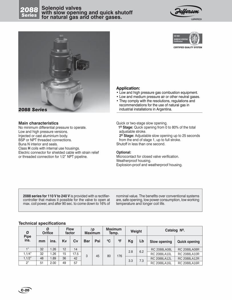
C-20
2088Series
Solenoid valveswith slow opening and quick shutofffor natural gas and other gases.
Main characteristicsNo minimum differential pressure to operate.Low and high pressure versions.Injected or cast aluminium body.BSP or NPT threaded connections.Buna N interior and seals.Class H coils with internal use housings.Electric connector for shielded cable with strain relief or threaded connection for 1/2” NPT pipeline.
2088 Series
Quick or two-stage slow opening. 1º Stage: Quick opening from 0 to 80% of the total adjustable stroke. 2º Stage: Adjustable slow opening up to 25 seconds from the end of stage 1, up to full stroke.Shutoff in less than one second.
Optional:Microcontact for closed valve verifi cation.Weatherproof housing.Explosion-proof and weatherproof housing.
Application:• Low and high pressure gas combustion equipment.• Low and medium pressure air or other neutral gases.• They comply with the resolutions, regulations and recommendations for the use of natural gas in industrial installations in Argentina.
CERTIFIED QUALITY SYSTEM
2088 series for 110 V to 240 V is provided with a rectifi er- controller that makes it possible for the valve to open at max. coil power, and after 90 sec. to come down to 16% of
nominal value. The benefi ts over conventional systems are, safe opening, low power consumption, low working temperature and longer coil life.
1”1,1/4”1,1/2”
2”
12153649
3 80
RC 2088LA08LRC 2088LA10LRC 2088LA12LRC 2088LA16L
RC 2088LA08RRC 2088LA10RRC 2088LA12RRC 2088LA16R
32324851
1.261.261.892.00
176
1417.54257
452.8
3.3
6.2
7.3
BarCvmm ins. Kv
Flowfactor
Technical specifi cations∆p
Maximum
Psi
MaximumTemp.
0C 0F
Catalog Nº.
Slow opening Quick opening
Weight
Kg Lb
ØPipeins.
Ø Orifi ce
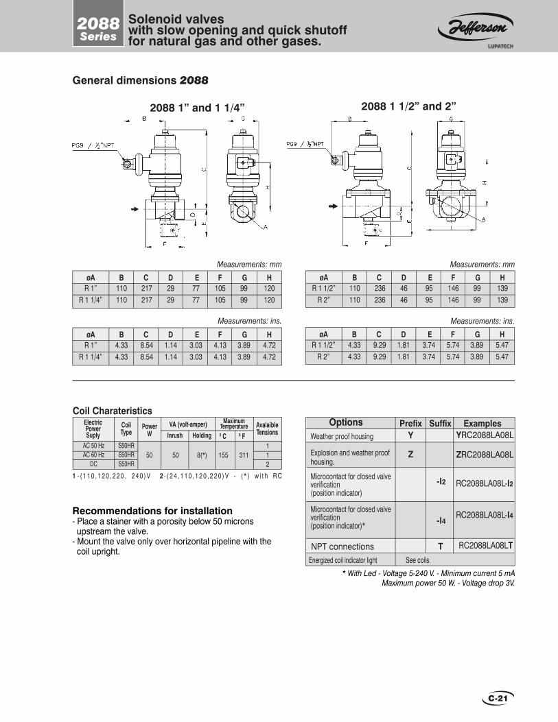
C-21
2088Series
Solenoid valveswith slow opening and quick shutofffor natural gas and other gases.
General dimensions 2088
2088 1” and 1 1/4” 2088 1 1/2” and 2”
Recommendations for installation- Place a stainer with a porosity below 50 microns upstream the valve.- Mount the valve only over horizontal pipeline with the coil upright.
Measurements: mmBøA D E F G H
R 1 1/2” R 2”
C110110
236236
4646
9595
146146
9999
139139
BøA D E F G HR 1”
R 1 1/4”
C110110
217217
2929
7777
105105
9999
120120
Measurements: mm
BøA D E F G HR 1”
R 1 1/4”
C4.334.33
8.548.54
1.141.14
3.033.03
4.134.13
3.893.89
4.724.72
Measurements: ins. Measurements: ins.BøA D E F G H
R 1 1/2” R 2”
C4.334.33
9.299.29
1.811.81
3.743.74
5.745.74
3.893.89
5.475.47
1 - ( 1 1 0 , 1 2 0 , 2 2 0 , 2 4 0 ) V 2 - ( 2 4 , 1 1 0 , 1 2 0 , 2 2 0 ) V - ( * ) w i t h R C
AC 50 HzAC 60 Hz
DC
VA (volt-amper)
S50HRS50HRS50HR
112
0 C 0 F
155
Coil CharateristicsElectricPowerSuply
AvalaibleTensions
CoilType
PowerW Inrush Holding
MaximumTemperature
50 50 8(*) 311
* With Led - Voltage 5-240 V. - Minimum current 5 mA Maximum power 50 W. - Voltage drop 3V.
OptionsWeather proof housing
Explosion and weather proof housing.
Microcontact for closed valve verifi cation (position indicator)
Microcontact for closed valve verifi cation (position indicator)*
Prefi x Y
Z
Examples Suffi xYRC2088LA08L
ZRC2088LA08L
-I4
Energized coil indicator light See coils.
T
RC2088LA08L-I2
RC2088LA08L-I4
-I2
NPT connections RC2088LA08LT
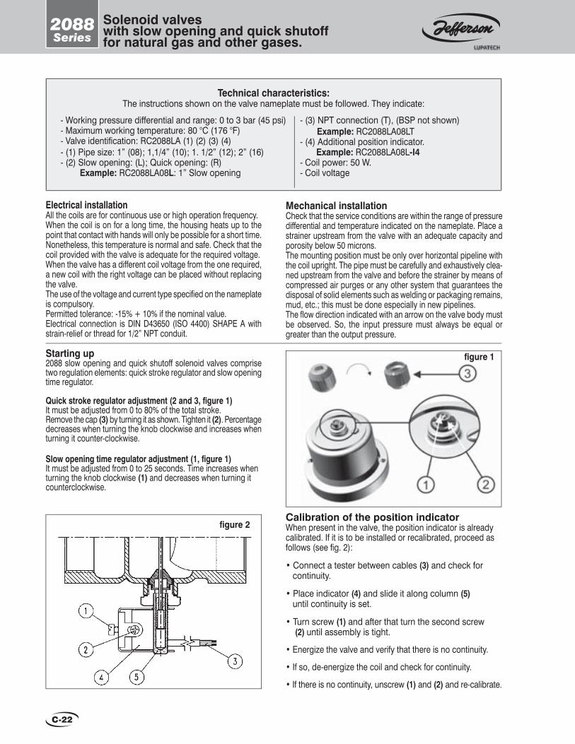
C-22
2088Series
Solenoid valveswith slow opening and quick shutofffor natural gas and other gases.
Technical characteristics:The instructions shown on the valve nameplate must be followed. They indicate:
- Working pressure differential and range: 0 to 3 bar (45 psi) - Maximum working temperature: 80 °C (176 °F)- Valve identifi cation: RC2088LA (1) (2) (3) (4) - (1) Pipe size: 1” (08); 1,1/4” (10); 1. 1/2” (12); 2” (16) - (2) Slow opening: (L); Quick opening: (R) Example: RC2088LA08L: 1” Slow opening
- (3) NPT connection (T), (BSP not shown) Example: RC2088LA08LT- (4) Additional position indicator. Example: RC2088LA08L-I4- Coil power: 50 W.- Coil voltage
Electrical installationAll the coils are for continuous use or high operation frequency.When the coil is on for a long time, the housing heats up to the point that contact with hands will only be possible for a short time. Nonetheless, this temperature is normal and safe. Check that the coil provided with the valve is adequate for the required voltage. When the valve has a different coil voltage from the one required, a new coil with the right voltage can be placed without replacing the valve. The use of the voltage and current type specifi ed on the nameplate is compulsory.Permitted tolerance: -15% + 10% if the nominal value.Electrical connection is DIN D43650 (ISO 4400) SHAPE A with strain-relief or thread for 1/2” NPT conduit.
Mechanical installationCheck that the service conditions are within the range of pressure differential and temperature indicated on the nameplate. Place a strainer upstream from the valve with an adequate capacity and porosity below 50 microns.The mounting position must be only over horizontal pipeline with the coil upright. The pipe must be carefully and exhaustively clea-ned upstream from the valve and before the strainer by means of compressed air purges or any other system that guarantees the disposal of solid elements such as welding or packaging remains, mud, etc.; this must be done especially in new pipelines.The fl ow direction indicated with an arrow on the valve body must be observed. So, the input pressure must always be equal or greater than the output pressure.
Starting up2088 slow opening and quick shutoff solenoid valves comprise two regulation elements: quick stroke regulator and slow opening time regulator.
Quick stroke regulator adjustment (2 and 3, fi gure 1)It must be adjusted from 0 to 80% of the total stroke.Remove the cap (3) by turning it as shown. Tighten it (2). Percentage decreases when turning the knob clockwise and increases when turning it counter-clockwise.
Slow opening time regulator adjustment (1, fi gure 1)It must be adjusted from 0 to 25 seconds. Time increases whenturning the knob clockwise (1) and decreases when turning itcounterclockwise.
Calibration of the position indicatorWhen present in the valve, the position indicator is already calibrated. If it is to be installed or recalibrated, proceed as follows (see fi g. 2):
• Connect a tester between cables (3) and check for continuity.
• Place indicator (4) and slide it along column (5) until continuity is set.
• Turn screw (1) and after that turn the second screw (2) until assembly is tight.
• Energize the valve and verify that there is no continuity.
• If so, de-energize the coil and check for continuity.
• If there is no continuity, unscrew (1) and (2) and re-calibrate.
fi gure 2
fi gure 1

C-23
V171Series Thermoelectric
safety valves.
Applications:•Secutity systems for natural gas and LPG burners.V171 Series
CERTIFIED QUALITY SYSTEM
Construction characteristicsInjected aluminum body.Seats: Buna N.Interior: brass, stainless steel.BSP or NPT 3/4” connections.BSP or NPT 1/8” pilot connection.Maximum torque: 30 Nm ( 22 lb.ft ).Thermocouple connection: M9 x 1.Maximum torque: 4 Nm (3 lb.ft)
Technical characteristicsNo minimum pressure to operate.Opening time: 5 seconds.Cut off time due to lack of fl ame: < 1 second.Observations:Cut off time due to lack of fl ame depends on valve + thermocouple assembly, which should be: < 45 sec.
Additional featuresStandard thermocouples: 16”, 24” and 47” (400, 600, 800, 1200 and 2000 mm).
Technical specifi cations
19
19
9
Ø Orifi ce
mm ins. Kv Cv
Flowfactor
0.2
1.5
1.5
3
22
22
psibar
Maximumpressure
-10 14
0F0C
Minimum temperature
80 176
0F0C
Maximum temperature
LbKg
WeightCatalog N0 Pilot
V171 P06
V171-2
V171-3
si
no
si
0.75
0.75
0.35
4.2
4.2
1.9
4.9
4.9
2.2
0.44
0.43
0.44
0.97
0.95
0.97
V171 General dimensions
R 1/8”
A
R 3/
4”
B
C
Ø D
E
R 3/4”
Measurements: mm
A B C54 81 57
Ø D E41 31
Measurements: ins.
A B C2.12 3.18 2.24
Ø D E1.61 1.22
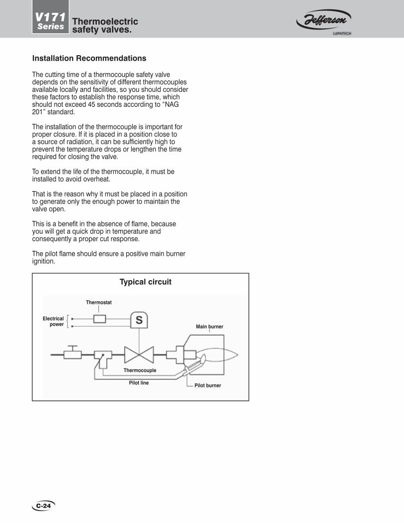
C-24
V171Series Thermoelectric
safety valves.
Typical circuit
Electricalpower
Thermostat
Pilot line
Thermocouple
Pilot burner
Main burner
Installation Recommendations
The cutting time of a thermocouple safety valve depends on the sensitivity of different thermocouples available locally and facilities, so you should consider these factors to establish the response time, which should not exceed 45 seconds according to “NAG 201” standard.
The installation of the thermocouple is important for proper closure. If it is placed in a position close to a source of radiation, it can be suffi ciently high to prevent the temperature drops or lengthen the time required for closing the valve.
To extend the life of the thermocouple, it must be installed to avoid overheat.
That is the reason why it must be placed in a position to generate only the enough power to maintain the valve open.
This is a benefi t in the absence of fl ame, because you will get a quick drop in temperature and consequently a proper cut response.
The pilot fl ame should ensure a positive main burner ignition.

D-1
1323 1325 1339
1350 1351 1365
1375
3, 4 and 5 WaySolenoid Valves for Pneumatic and Hydraulic Use
1387 BA 1-N 1387 BA2-N
1387 Series
D-15
1375 Series
D-14
1365 Series
D-12 / D-13
1351 Series
D-10 / D-11
1350 Series
D-8 / D-9
1339 Series
D-6 / D-7
1325 Series
D-4 / D-5
1323 Series 3 ways.N.closed and N.open or universal. Direct acting.
3 ways.N.closed and N.open.Pilot operated.
4/3 ways.Closed center.Pilot operated.
5 ways.Monostable and bistable.Pilot operated.
3 ways.N. closed, N. open Monostable or bistable.Pilot operated.
3 waysN. closed, N. open or universal. Direct acting.
5 ways. Direct NAMUR mount.Pilot operated.
3 ways. N. closed.Direct NAMUR mount. Direct acting or pilot operated.
D-2 / D-3
Pages
New products NEW SOLENOID VALVE MODELS
• Intrinsically Safe.• Low Power.• ATEX Explosion-Proof Coils.
To request a technical bulletin for models that are not included in this catalog, please contact JEFFERSON at:
2051 Series
D-16 / D-17
5 ways.Monostable and bistable.Pilot operated.
3 ways.N. closed, N. open Monostable or bistable.Pilot operated.
3 ways and 5 ways.Direct NAMUR mount.Pilot operated.
Additional information
5 ways. Pilot operated.
2050 Series
D-18 / D-19
Pages
SI Series
D-20 / D-21
2095 Series
D-22 / D-23
2024 Series D-24
2050 2095 2051 2024
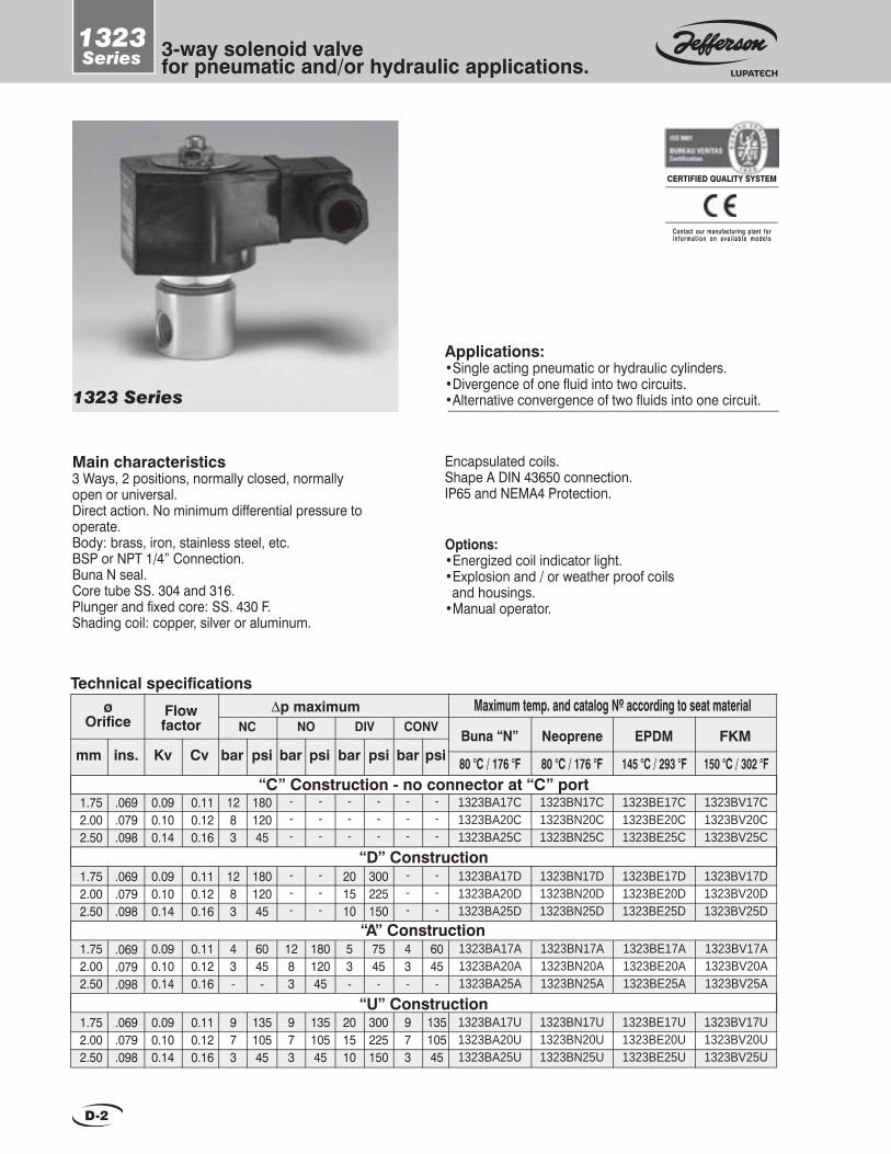
D-2
3-way solenoid valve for pneumatic and/or hydraulic applications.
1323Series
Main characteristics3 Ways, 2 positions, normally closed, normally open or universal.Direct action. No minimum differential pressure to operate.Body: brass, iron, stainless steel, etc.BSP or NPT 1/4” Connection.Buna N seal.Core tube SS. 304 and 316.Plunger and fi xed core: SS. 430 F.Shading coil: copper, silver or aluminum.
1323 Series
Encapsulated coils.Shape A DIN 43650 connection.IP65 and NEMA4 Protection.
Options:•Energized coil indicator light.•Explosion and / or weather proof coils and housings.•Manual operator.
Applications:•Single acting pneumatic or hydraulic cylinders.•Divergence of one fl uid into two circuits.•Alternative convergence of two fl uids into one circuit.
CERTIFIED QUALITY SYSTEM
Contact our manufacturing plant forin format ion on ava i lab le models
1.752.002.50
0.090.100.14
1323BA17U1323BA20U1323BA25U
13510545
1323BE17U1323BE20U1323BE25U
1323BV17U1323BV20U1323BV25U
1323BN17U1323BN20U1323BN25U
973
13510545
201510
300225150
973
13510545
1.752.002.50
0.090.100.14
1323BA17A1323BA20A1323BA25A
6045-
1323BE17A1323BE20A1323BE25A
1323BV17A1323BV20A1323BV25A
1323BN17A1323BN20A1323BN25A
1283
18012045
53-
7545-
43-
6045-
Maximum temp. and catalog Nº according to seat material∆p maximumFlow factor
Technical specifi cations
NC NO DIV CONV
1.752.002.50
0.090.100.14
1323BA17C1323BA20C1323BA25C
18012045
1323BE17C1323BE20C1323BE25C
1323BV17C1323BV20C1323BV25C
1323BN17C1323BN20C1323BN25C
psibarmm ins. Kv CvBuna “N” Neoprene
barpsi psi psibarbarFKMEPDM
---
---
---
---
---
---
1.752.002.50
0.090.100.14
1323BA17D1323BA20D1323BA25D
18012045
1323BE17D1323BE20D1323BE25D
1323BV17D1323BV20D1323BV25D
1323BN17D1323BN20D1323BN25D
---
---
201510
300225150
---
---
“C” Construction - no connector at “C” port
“D” Construction
“A” Construction
“U” Construction.069.079.098
.069
.079
.098
.069
.079
.098
.069
.079
.098
0.110.120.16
0.110.120.16
0.110.120.16
0.110.120.16
973
43-
1283
1283
ø Orifi ce
80 °C / 176 °F 80 °C / 176 °F 145 °C / 293 °F 150 °C / 302 °F

D-3
3-way solenoid valve for pneumatic and/or hydraulic applications.
1323Series
General dimensions
B
C
R1/4” G
H
R1/4”
R W3/16”
I
D (“
D”
,”A”
& “
U”
cons
truc
tion)
Pg9
A VIEWMounting details
1 - ( 2 4 , 1 1 0 , 2 2 0 ) V 2 - ( 2 4 , 1 1 0 , 1 2 0 , 2 4 0 ) V 3 - ( 1 2 , 2 4 , 1 1 0 , 2 2 0 ) V
Coil characteristicsElectricpowersupply
AC 50 Hz
AC 60 Hz
DC
Availabletensions
MaximumtemperatureCoil
typePower
WVA (volt-amper)
Inrush MF11CMH11CMF13CMH13CMH19C
1111131319
11223
Holding4040454519
2222272719
155 180 155 180 180
311356311356356
OptionsWater, weather and saline corrosion proof coils. Explosion and weather proof coils.Weather proof housing. Explosion and weather proof housing. Manual operator: on the main orificeNPT connections
Prefix YC
ZC
Y
Z
Examples SuffixYC1323BA17C
ZC1323BA17C
Y1323BA17D
Z1323BA17D
1323BA17C-M
1323BA17CT
- M
T Energized coil indicator light See coils.
C
Measurements: mm
B C D E F G H I57 22 100 85 10 85 27 20
Measurements: ins.
B C D E F G H I2.24 0.87 3.93 3.35 0.39 3.35 1.06 0.79
Special constructionsStainless steel body.•AISI 304: change letter B for S in the catalog Nº. Example: 1323SA17C •AISI 316: change letter B for I in the catalog Nº. Example: 1323IA17C
0C 0F
A
E (“
C”
cons
truc
tion)
F
A B
Recommendations for installationPlace a strainer upstream the valve with a porosity ≤ 100 µ.Installation: in any position, preferably over horizontal pipeline with the coil upright. Except “C”, all the constructions may be used for any operation manner, but it is advisable to choose the valve according to its use in order to obtain the best performance.
C or D A D U U
NC NO Divergent Convergent UniversalOperation
Energized
De-Energized
Construc.Flow diagrams

D-4
1325Series
3/2 way solenoid valves high capacity.
Main characteristics3 ways, 2 positions, normally closed, normally open.Diaphragm servo-operated action with metal core.Seat shutoff. No need for lubrication to operate.Body: brass, stainless steel, etc.BSP or NPT threaded connections.Buna N diaphragm and seats for neutral fl uids up to 80 °C (176 °F).FKM diaphragm and seats for other uses.Core tube SS. 304 and 316.Plunger and fi xed core: SS. 430 F.Shading coil: copper, silver or aluminum.Weight: 2 kg (4.42 lb).
Encapsulated coils.Shape A DIN 43650 connection.IP65 and NEMA4 Protection.Pilot orifi ce with internal discharge. It may be used with fl uids which cannot be discharged into the atmosphere.Greater fl ow capacity and lower response time than any other spool valve of the same size.
Options:•Energized coil indicator light.•Explosion and / or weather proof coils and housings.
Applications:•Large single acting cylinders or actuators, compressors, turbines, etc.•Ideal for instrument air or dry gas.•It can also operate with lubricated air, water, light oils, etc.
UnderwritersLaboratories Inc.®
CanadianStandards
Associationcanadienne denormalisation
Association
CERTIFIED QUALITY SYSTEM
Contact our manufacturing plant forin format ion on ava i lab le models
1325 Series
2.73.44.7
1325SA3A1325SA4A1325SA6A
0.51325SV3A1325SV4A1325SV6A
10
2.73.44.7
1325SA3C1325SA4C1325SA6C
0.51325SV3C1325SV4C1325SV6C
10
∆p Flow factor Minimum Maximum
2.73.44.7
1325BA3C1325BA4C1325BA6C
0.51325BV3C1325BV4C1325BV6C
psibarmm ins. Kv CvBuna “N” FKM
psibar
10
2.73.44.7
1325BA3A1325BA4A1325BA6A
0.51325BV3A1325BV4A1325BV6A
10
0.63
0.63
0.63
0.63
Maximum temp. and catalog Nº according to seat material
Technical specifi cations
Forged Brass Body - Normally closed
Forged brass body - Normally open
Stainless steel body AISI 304 - Normally closed
Stainless steel body AISI 304 - Normally open3/8”1/2”3/4”
3/8”1/2”3/4”
3/8”1/2”3/4”
3/8”1/2”3/4”
16
16
16
16
3.24.05.5
3.24.05.5
3.24.05.5
3.24.04.7
7.5
7.5
7.5
7.5
150
150
150
150
ø Orifi ceø
Pipe ins.
80 °C / 176 °F 150 °C / 302 °F

D-5
1325Series
3/2 way solenoid valves high capacity.
Measurements: mm
B CøA D E F G H3/8”1/2”3/4”
85 27 103 29 43 121 90
General dimensions
C
øA
F
GE
D
Pg9
H
B
Measurements: ins.
B CøA D E F G H3/8”1/2”3/4”
3.34 1.06 4.05 1.14 1.69 4.76 3.54
P R
A
1 - ( 2 4 , 1 1 0 , 2 2 0 ) V 2 - ( 2 4 , 1 1 0 , 1 2 0 , 2 4 0 ) V 3 - ( 1 2 , 2 4 , 1 1 0 , 2 2 0 ) V
Coil characteristicsElectricpowersupply
AC 50 Hz
AC 60 Hz
DC
Availabletensions
MaximumtemperatureCoil
typePower
WVA (volt-amper)
Inrush Holding 0C 0F
MF11C
MF13C
MH19
11
13
19
1
2
3
40
45
19
22
17
19
155
155
180
311
311
356
OptionsWater, weather and saline corrosion proof coils. Explosion and weather proof coils.Weather proof housing.
Explosion and weather proof housing. NPT connections
Prefix YC
ZC
Y
Z
Examples SuffixYC1325BA4C
ZC1325BA4C
Y1325BA4C
Z1325BA4C
1325BA4CTT Energized coil indicator light See coils.
Recommendations for installationPlace a strainer upstream of the valve with a porosity ≤ 100 µ. Installation: in any position. Preferably on a horizontal pipeline with the coil upright.
Energized De-energized Symbols
Nor
mal
ly o
pen
Nor
mal
ly c
lose
d
Flow diagrams

D-6
1339Series
4/3 way solenoid valves.Closed center.
1339 Series
Main characteristics4 ways, 3 positions, closed center.It allows to operate double acting cylinders or actuators.Aluminium, brass and stainless steel body.BSP or NPT 1/4”, 3/8”, 1/2” threaded connections.Seat shutoff, 4 diaphragms which plug up the respective ways.High capacity and operation speed.No need for lubrication to operate, ideal forinstrument air.Pilot orifi ces with internal discharge, it may operate dangerous fl uids or those which do not allow spills,
such as gas, fuel, water, light oils and other similar fl uids.Buna N seals.Core tube SS. 304 and 316.Plunger and fi xed core: SS. 430 F.Shading coil: copper, silver or aluminiumShape A DIN 43650 connection encapsulated coils.IP65 and NEMA 4 protection.
Options:•Energized coil indicator light.•Explosion and / or weather proof coils and housings.
Applications:•Ideal for application where graduated or full stroke of piston is required.•High fl ow; exceptionally long life; heavy-duty operation.•Dry air, gas, water, light oil and others gases and liquids.
CERTIFIED QUALITY SYSTEM
Contact our manufacturing plant forin format ion on ava i lab le models
1/4”3/8”1/2”
1/4”3/8”1/2”
Maximum temp. and catalog Nº according to seat material∆p minimum
Flow factor
Technical specifi cations
888
0.340.681.27
1339LA11339LA21339LA3
0.51339SA11339SA21339SA3
1339BA11339BA21339BA3
psibarmm ins. Kv Cv Aluminium Brassbar psi AISI.304
888
0.340.681.27
1339LV11339LV21339LV3
1339SV11339SV21339SV3
1339BV11339BV21339BV3
Pressure differential∆p maximum
10
kg
Weight
Lb
1.30.230.310.39
0.230.310.39
Buna “N” diaphragm
7.5 150
0.5 107.5 150
Alum Br/ss
2.2
1.3 2.2
2.9 4.9
2.9 4.9
Alum Br/ss
0.40.81.5
0.40.81.5
ø Orifi ce ø
Pipeins.
FKM diaphragm
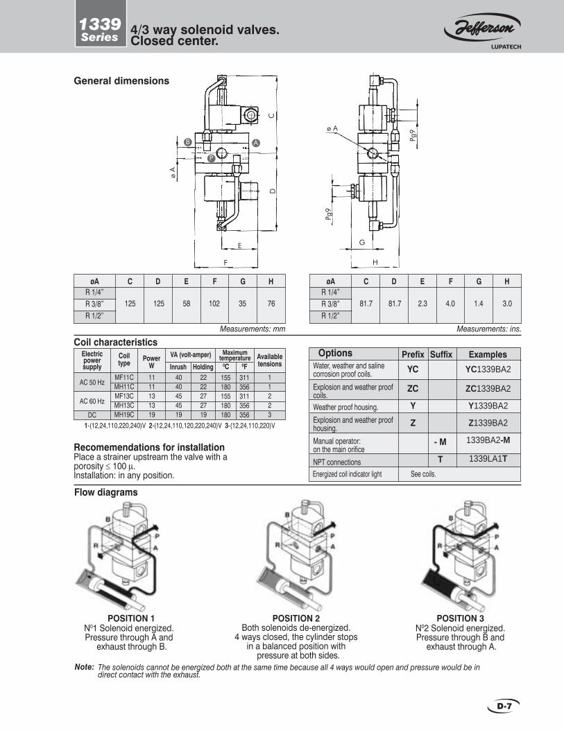
D-7
1339Series
4/3 way solenoid valves.Closed center.
General dimensions
Recomemendations for installationPlace a strainer upstream the valve with a porosity ≤ 100 µ.Installation: in any position.
E
F H
G
ø A
Pg9
Pg9
CD
ø A
OptionsWater, weather and saline corrosion proof coils. Explosion and weather proof coils.Weather proof housing.Explosion and weather proof housing.Manual operator: on the main orificeNPT connections
Prefix YC
ZC
Y
Z
Examples SuffixYC1339BA2
ZC1339BA2
Y1339BA2
Z1339BA2
1339BA2-M
1339LA1T
- M
T Energized coil indicator light See coils.
1-(12,24,110,220,240)V 2-(12,24,110,120,220,240)V 3-(12,24,110,220)V
Coil characteristicsElectricpowersupply
AC 50 Hz
AC 60 Hz
DC
Availabletensions
MaximumtemperatureCoil
type PowerW
VA (volt-amper)
Inrush MF11CMH11CMF13CMH13CMH19C
1111131319
4040454519
2222272719
11223
Holding 0C 0F155 180 155 180 180
311356311356356
Measurements: mm
CøA D E F G HR 1/4”R 3/8” R 1/2”
125 125 58 102 35 76
Measurements: ins.
CøA D E F G HR 1/4”R 3/8” R 1/2”
81.7 81.7 2.3 4.0 1.4 3.0
P
AB
Note:
POSITION 1N01 Solenoid energized.Pressure through A and
exhaust through B.
POSITION 3N02 Solenoid energized.Pressure through B and
exhaust through A.
The solenoids cannot be energized both at the same time because all 4 ways would open and pressure would be in direct contact with the exhaust.
POSITION 2Both solenoids de-energized.
4 ways closed, the cylinder stops in a balanced position with
pressure at both sides.
Flow diagrams

D-8
1350Series
5/2 way solenoid valvesfor double acting cylinder.
Main characteristics5 ways, 2 positions, monostable or bistable.Slide servo-operated action.Internal or external pilot: electropneumatic or pneumatic.BSP or NPT threaded connections.Aluminium, brass, stainless steel body.Buna N seals for neutral fl uids up to 80 °C (176 °F).FKM seals for other uses.PTFE sleeve for instrument air and dry gases.Core tube SS. 304 and 316.Plunger and fi xed core: SS. 430 F.Shading coil: copper, silver or aluminiumShape A DIN 43650 connection encapsulated coils.IP65 and NEMA 4 protection.
1350 Series
Applications:•Double acting cylinders or diaphragms valves. •Lubricated or dry air-gas, water, light oil.•Heavy-duty operation.
Note: The pilot signal with independent pilots or pneumatic operators must be 1 bar and equal or greater than the valve working pressure.
UnderwritersLaboratories Inc.®
To request a technical bulletin for models that are not included in
this catalog, please contact JEFFERSON at:
New products• Intrinsically Safe.• Low Power.• ATEX Explosion-Proof Coils.
CERTIFIED QUALITY SYSTEM
Contact our manufacturing plant forin format ion on ava i lab le models
CanadianStandardsAssociation
Associationcanadienne denormalisation
Options:•Energized coil indicator light.•Explosion and / or weather proof coils and housings.•Manual operator.
DF
0 10
Max
ABC
10.50.5
10
GI 0 10
Minbar psi bar psi
Electric operator with internal pilot
Electric operator with independent pilot
Pneumatic operator0
157.57.5
0
150
150
150
Suffi xMain line supply press.
Operation manner
Spring returnPneumatic return
Bistable
Spring return Bistable
Spring return Bistable
1/4”3/8”1/2”
7710
0.800.961.90
NO1350SV1*1350SV2*1350SV3*
0.270.270.39
1/4”3/8”
1/4”3/8”1/2”
No sleeve
Flowfactor
Technical specifi cations
77
0.800.96
1350LV1*1350LV2*
1350LTV1*1350LTV2*
mm ins. Kv Cv
7710
0.800.961.90
1350BV1*1350BV2*1350BV3*
1350BTV1*1350BTV2*1350BTV3*
Buna “N” seals
with sleeve
Aluminium body 0.270.27
0.270.270.39
FKM seals
No sleeve with sleeve
Stainless steel body AISI 304
NO1350SA1*1350SA2*1350SA3*
1350BA1*1350BA2*1350BA3*
1350BTA1*1350BTA2*1350BTA3*
1350LA1*1350LA2*
1350LTA1*1350LTA2*
(*) The suffi x corresponding to the operation manner must be added to the catalog number according to the table Example: 1350LA1A.
0.941.122.22
0.941.12
0.941.122.22
øPipeins.
ø Orifi ce
Brass body
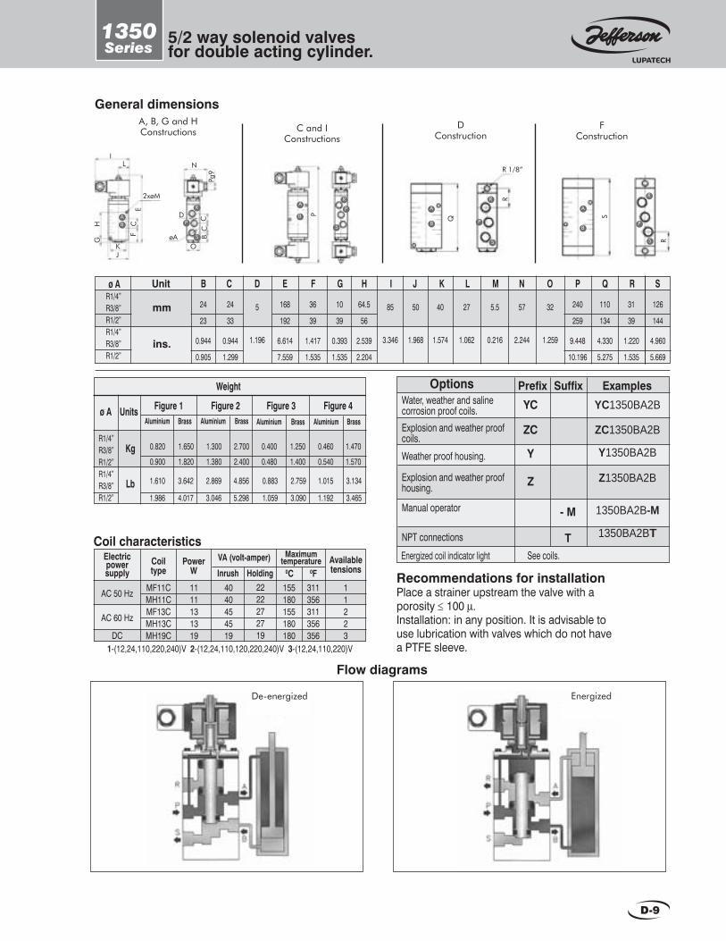
D-9
1350Series
5/2 way solenoid valvesfor double acting cylinder.
A, B, G and H Constructions
General dimensionsD
ConstructionF
ConstructionC and I
Constructions
P
R 1/8”
Q
R
R1/4”R3/8”R1/2”R1/4”R3/8”R1/2”
ø A B C D E F G H I J
24
23
0.944
0.905
K L M N O P Q R SUnit
mm
ins.
24
33
0.944
1.299
5
1.196
168
192
6.614
7.559
36
39
1.417
1.535
10
39
0.393
1.535
64.5
56
2.539
2.204
85
3.346
50
1.968
40
1.574
27
1.062
5.5
0.216
57
2.244
32
1.259
240
259
9.448
10.196
110
134
4.330
5.275
31
39
1.220
1.535
126
144
4.960
5.669
S
R
B
AR
P
S
A
B
R
P
S
B
A
R
P
S
IL
2xøM
E
H
FC
KJ
G
O
D
øA BC
CPg
9
N
AB
S
P
R
Recommendations for installationPlace a strainer upstream the valve with a porosity ≤ 100 µ. Installation: in any position. It is advisable to use lubrication with valves which do not have a PTFE sleeve.1-(12,24,110,220,240)V 2-(12,24,110,120,220,240)V 3-(12,24,110,220)V
Coil characteristicsElectricpowersupply
AC 50 Hz
AC 60 Hz
DC
Availabletensions
MaximumtemperatureCoil
typePower
WVA (volt-amper)
Inrush MF11CMH11CMF13CMH13CMH19C
1111131319
4040454519
2222272719
11223
Holding 0C 0F155 180 155 180 180
311356311356356
R1/4”R3/8”R1/2”R1/4”R3/8”R1/2”
Figure 1Aluminium Brass
Figure 2Aluminium Brass
Weight
0.820
0.900
1.650
1.820
1.610
1.986
1.300
1.380
2.700
2.400
ø AAluminium Brass Aluminium Brass
Figure 3 Figure 4 Units
Kg
Lb
0.400
0.480
1.250
1.400
0.460
0.540
1.470
1.570
3.642
4.017
2.869
3.046
4.856
5.298
0.883
1.059
2.759
3.090
1.015
1.192
3.134
3.465
OptionsWater, weather and saline corrosion proof coils. Explosion and weather proof coils.
Weather proof housing.
Explosion and weather proof housing.
Manual operator
NPT connections
Prefix YC
ZC
Y
Z
Examples SuffixYC1350BA2B
ZC1350BA2B
Y1350BA2B
Z1350BA2B
1350BA2B-M
1350BA2BT
- M
T Energized coil indicator light See coils.
Flow diagrams
De-energized Energized

D-10
1351Series
3/2 way solenoid valves for single acting cylinders.
1351 Series
Applications:•Single acting cylinders or diaphragms valves. •Lubricated or dry air-gas, water, light oil•Heavy-duty operation.
CERTIFIED QUALITY SYSTEM
Contact our manufacturing plant forin format ion on ava i lab le models
CanadianStandardsAssociation
Associationcanadienne denormalisation
UnderwritersLaboratories Inc.®
New products• Intrinsically Safe.• Low Power.• ATEX Explosion-Proof Coils.
To request a technical bulletin for models that are not included in
this catalog, please contact JEFFERSON at:
Main characteristics3 ways, 2 positions, normally open or normally closed.Slide servo-operated action.Internal or external pilot: electropneumatic or pneumatic.BSP or NPT threaded connections.Aluminium, brass, stainless steel body.Buna N seals for neutral fl uids up to 80 °C (176 °F).FKM seals for other uses.PTFE sleeve for instrument air and dry gases.Shape A DIN 43650 connection encapsulated coils.IP65 and NEMA 4 protection.
Options:•Energized coil indicator light.•Explosion and/or weather proof coils and housings.•Manual operator.
The pressure at the pilot signal with and independent pilot or a pneumatic operator must be 1 bar and equal or greater than the valve’s working pressure.
Note:
DJF
0
10
N. closed. Spring returnN. open. Spring return
Bistable
KNM
0
10
ABCGH
10.50.51
0.5
Operation manner
10
N. closed. Spring returnN. open. Spring return
Bistable
N. closed. Spring returnN. closed. Pneumatic return
BistableN. open. Spring return.
N. open. Pneumatic return
MaxMinbar psi bar psi
Electric operator with internal pilot
Electric operator with independent pilot
Pneumatic operator
0
0
157.57.5157.5
150
150
150
(* ) The su f f i x cor respond ing to the opera t ion mus t be added to the ca ta log number accord ing to the tab le Example : 1351LA1A .
1/4”3/8”1/2”
7710
0.800.961.90
1351SV1*1351SV2*1351SV3*
NO0.270.270.39
ø Pipe ins.
1/4”3/8”1/2”
1/4”3/8”1/2”
No sleeve
Flow factor
Technical specifi cations
7710
0.800.961.90
1351LTV1*1351LTV2*1351LTV3*
1351LV1*1351LV2*1351LV3*
mm ins. Kv Cv
7710
0.800.961.90
1351BTV1*1351BTV2*1351BTV3*
1351BV1*1351BV2*1351BV3*
with sleeve
0.270.270.39
0.270.270.39
No sleeve with sleeve
Stainless steel body AISI 3041351SA1*1351SA2*1351SA3*
NO
1351BTA1*1351BTA2*1351BTA3*
1351BA1*1351BA2*1351BA3*
1351LTA1*1351LTA2*1351LTA3*
1351LA1*1351LA2*1351LA3*
0.941.122.22
0.941.122.22
0.941.122.22
Buna “N” seals FKM seals
Suffi xMain line supply press.
ø Orifi cio
Brass body
Aluminium body

D-11
1351Series
3/2 way solenoid valves for single acting cylinders.
General dimensions 1351
D, E, I and JConstructions
FConstruction
C and MConstructions
V
W UX
Y
S
T
R 1/8”
Q
R P
I
J
GH
E
D
K
L
E
2XØM
N
ØA
F
O BC
PG9
A, B, G, H, K, L, N and PConstructions
A
P
R
A
P
R
P
R
A
A
P
R
R1/4”R3/8”R1/2”R1/4”R3/8”R1/2”
ø A B C D E F G H I J
11
15
0.433
0.590
K L M N O P Q R S TUnit
mm
ins.
24
31
0.944
1.220
22
31
0.866
1.220
5
-
0.196
-
13
21.5
0.511
0.846
23
31
0.905
1.220
85
3.346
27
1.062
40
1.574
50
1.968
5.5
0.216
57
2.244
32
1.259
95
102
3.740
4.015
226
252
8.897
9.921
113
126
4.448
4.960
30
38
1.181
1.496
130
149
5.118
5.866
72
91
2.834
3.582
112
137
4049
5.393
7.5
-
0.295
-
5
3
0.196
0.118
37
47
1.456
1.850
V W X YU
56
68
2.204
2.677
R1/4”R3/8”R1/2”R1/4”R3/8”R1/2”
Figure 1Aluminium Brass
Figure 2Aluminium Brass
Weight
0.680
-
1.250
-
1.501
-
0.680
1.20
1.800
1.950
ø AAluminium Brass Aluminium Brass
Figure 3 Figure 4 Units
Kg
Lb
0.280
0.300
0.800
0.920
0.350
0.370
0.970
1.100
2.759
-
1.501
2.649
3.973
4.304
0.618
0.662
1.766
2.030
0.772
0.816
2.141
2.428
De-energized Energized
Recommendations for installationPlace a strainer upstream the valve with a porosity ≤ 100 µ. Installation: in any position. It is advisable to use lubricated air when valves have no PTFE sleeve.1-(12, 24,110,220,240)V 2-(12,24,110,120,220,240)V 3-(12,24,110,220)V
Coil characteristicsElectricpowersupply
AC 50 Hz
AC 60 Hz
DC
Availabletensions
MaximumtemperatureCoil
type PowerW
VA (volt-amper)
Inrush MF11CMH11CMF13CMH13CMH19C
1111131319
4040454519
2222272719
11223
Holding 0 C 0 F155 180 155 180 180
311356311356356
OptionsWater, weather and saline corrosion proof coils. Explosion and weather proof coils.
Weather proof housing.
Explosion and weather proof housing.
Manual operator: on the main orifice
NPT connections
Prefix YC
ZC
Y
Z
Examples SuffixYC1351BA2B
ZC1351BA2B
Y1351BA2B
Z1351BA2B
1351BA2B-M
1351BA2BT
- M
T Energized coil indicator light See coils.
Flow diagram (NC)
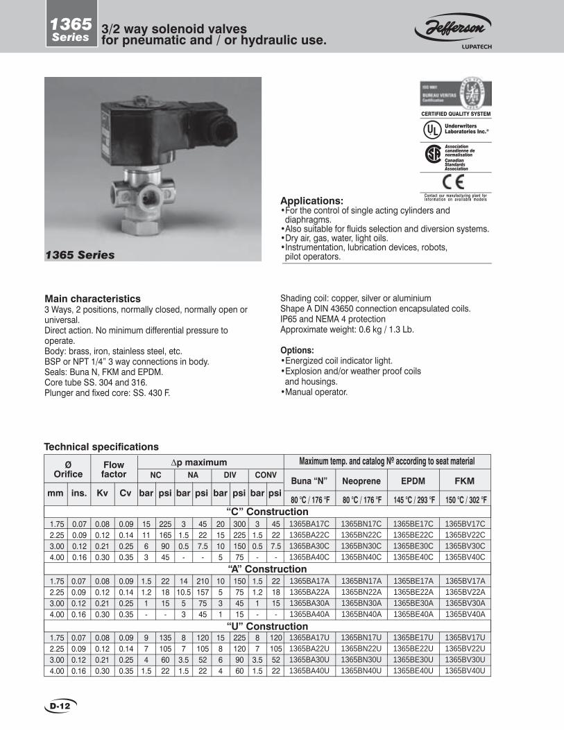
D-12
1365Series
3/2 way solenoid valves for pneumatic and / or hydraulic use.
Main characteristics3 Ways, 2 positions, normally closed, normally open or universal.Direct action. No minimum differential pressure to operate.Body: brass, iron, stainless steel, etc.BSP or NPT 1/4” 3 way connections in body.Seals: Buna N, FKM and EPDM.Core tube SS. 304 and 316.Plunger and fi xed core: SS. 430 F.
Shading coil: copper, silver or aluminiumShape A DIN 43650 connection encapsulated coils.IP65 and NEMA 4 protectionApproximate weight: 0.6 kg / 1.3 Lb.
Options:•Energized coil indicator light.•Explosion and/or weather proof coils and housings.•Manual operator.
1365 Series
Applications:•For the control of single acting cylinders and diaphragms. •Also suitable for fl uids selection and diversion systems.•Dry air, gas, water, light oils.•Instrumentation, lubrication devices, robots, pilot operators.
UnderwritersLaboratories Inc.®
CERTIFIED QUALITY SYSTEM
Contact our manufacturing plant forin format ion on ava i lab le models
CanadianStandardsAssociation
Associationcanadienne denormalisation
1.752.253.004.00
0.080.120.210.30
1365BA17U1365BA22U1365BA30U1365BA40U
974
1.5
1365BE17U1365BE22U1365BE30U1365BE40U
1365BV17U1365BV22U1365BV30U1365BV40U
1365BN17U1365BN22U1365BN30U1365BN40U
87
3.51.5
15864
87
3.51.5
Ø Orifi ce
Maximum temp. and catalog Nº according to seat material∆p maximumFlow factor
Technical specifi cations
NC NA DIV CONV
0.080.120.210.30
1365BA17C1365BA22C1365BA30C1365BA40C
151163
1365BE17C1365BE22C1365BE30C1365BE40C
1365BV17C1365BV22C1365BV30C1365BV40C
1365BN17C1365BN22C1365BN30C1365BN40C
psibarmm ins. Kv CvBuna “N” Neoprene
barpsi psi psibarbarFKMEPDM
31.50.5-
2015105
31.50.5-
0.080.120.210.30
1365BA17A1365BA22A1365BA30A1365BA40A
1.51.21-
1365BE17A1365BE22A1365BE30A1365BE40A
1365BV17A1365BV22A1365BV30A1365BV40A
1365BN17A1365BN22A1365BN30A1365BN40A
1410.5
53
10531
1.51.21-
1.752.253.004.00
1.752.253.004.00
“C” Construction
“A” Construction
“U” Construction0.070.090.120.16
0.070.090.120.16
0.070.090.120.16
0.090.140.250.35
0.090.140.250.35
0.090.140.250.35
1351056022
2251659045
221815-
1201055222
45227.5-
2101577545
2251209060
30022515075
150754515
1201055222
45227.5-
221815-
80 °C / 176 °F 80 °C / 176 °F 145 °C / 293 °F 150 °C / 302 °F
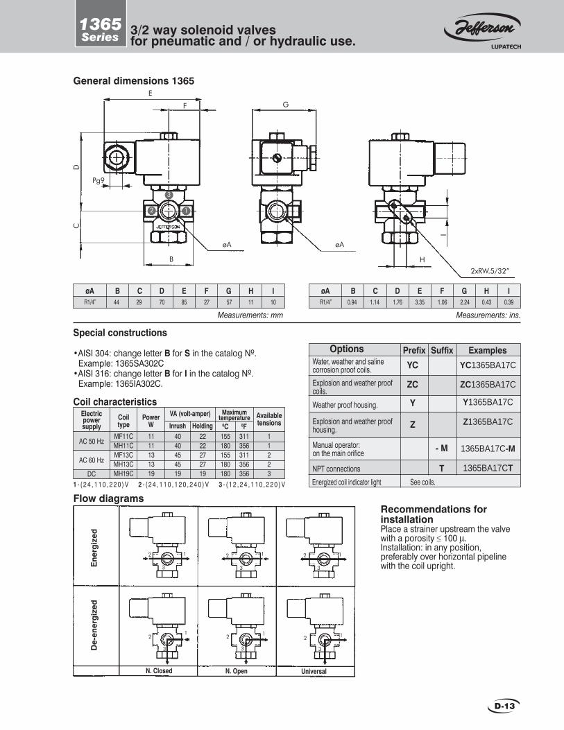
D-13
1365Series 3/2 way solenoid valves
for pneumatic and / or hydraulic use.
General dimensions 1365E
F
B
G
H
2xRW.5/32”
I
CD
Pg9
øA øA
B CøA D E F G H I
Measurements: mmR1/4” 44 29 70 85 27 57 11 10
B CøA D E F G H I
Measurements: ins.R1/4” 0.94 1.14 1.76 3.35 1.06 2.24 0.43 0.39
1 - ( 2 4 , 1 1 0 , 2 2 0 ) V 2 - ( 2 4 , 1 1 0 , 1 2 0 , 2 4 0 ) V 3 - ( 1 2 , 2 4 , 1 1 0 , 2 2 0 ) V
Coil characteristicsElectricpowersupply
AC 50 Hz
AC 60 Hz
DC
Availabletensions
MaximumtemperatureCoil
typePower
WVA (volt-amper)
Inrush MF11CMH11CMF13CMH13CMH19C
1111131319
11223
Holding 0C 0F4040454519
2222272719
155 180 155 180 180
311356311356356
OptionsWater, weather and saline corrosion proof coils. Explosion and weather proof coils.
Weather proof housing.
Explosion and weather proof housing.
Manual operator: on the main orifice
NPT connections
Prefix YC
ZC
Y
Z
Examples SuffixYC1365BA17C
ZC1365BA17C
Y1365BA17C
Z1365BA17C
1365BA17C-M
1365BA17CT
- M
T Energized coil indicator light See coils.
2
3
1
Special constructions
•AISI 304: change letter B for S in the catalog Nº. Example: 1365SA302C•AISI 316: change letter B for I in the catalog Nº. Example: 1365IA302C.
Flow diagrams
Ener
gize
dD
e-en
ergi
zed
N. Closed N. Open Universal
12
3
12
3
12
3
12
3
12
3
12
3
Recommendations for installationPlace a strainer upstream the valve with a porosity ≤ 100 µ.Installation: in any position, preferably over horizontal pipeline with the coil upright.
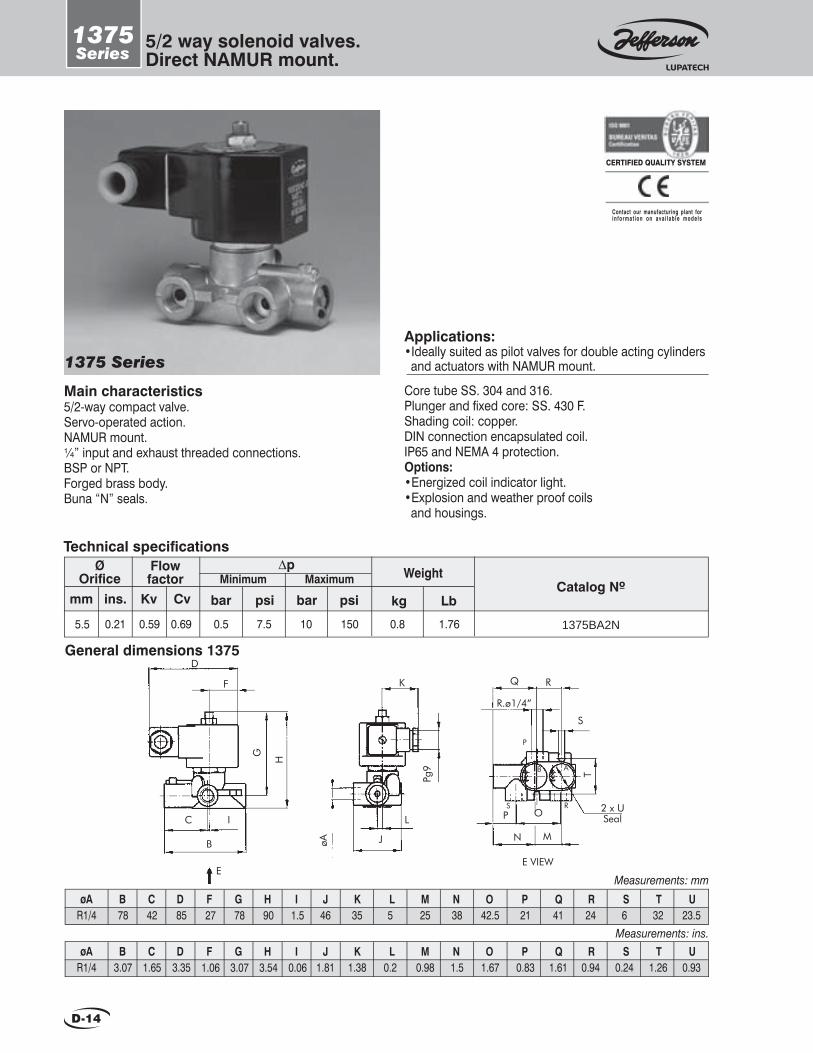
D-14
1375Series
5/2 way solenoid valves. Direct NAMUR mount.
Main characteristics5/2-way compact valve.Servo-operated action.NAMUR mount.¼” input and exhaust threaded connections.BSP or NPT.Forged brass body.Buna “N” seals.
Core tube SS. 304 and 316.Plunger and fi xed core: SS. 430 F.Shading coil: copper.DIN connection encapsulated coil.IP65 and NEMA 4 protection.Options:•Energized coil indicator light.•Explosion and weather proof coils and housings.
1375 Series
Applications:•Ideally suited as pilot valves for double acting cylinders and actuators with NAMUR mount.
5.5
Ø Orifi ce
Flow factor
Technical specifi cations
1375BA2N
mm ins. Kv Cv
∆p Minimum Maximum
psibar psibar kg
Weight
LbCatalog Nº
0.59 0.5 10 0.80.21 1.760.69 7.5 150
CERTIFIED QUALITY SYSTEM
Contact our manufacturing plant forin format ion on ava i lab le models
B CøA D78
F G42 85 27
H I J K78 90 1.5
Measurements: mm
R1/4 46 35L M N O P5 25 38 42.5 21
Q R S T41 24 6 32
U23.5
General dimensions 1375D
F
C I
B
G
H
K
J
L
øA
Pg9
Q R
R.ø1/4”
S
2 x USeal
N M
P ORS
P
B A
E VIEWE
T
B CøA D3.07
F G1.65 3.35 1.06
H I J K3.07 3.54 0.06
Measurements: ins.
R1/4 1.81 1.38L M N O P
0.2 0.98 1.5 1.67 0.83Q R S T
1.61 0.94 0.24 1.26U
0.93

D-15
1387Series 3/2 ways solenoid valves.
Direct NAMUR mount.
Main characteristicsNC 3/2 ways compact valve.Direct or servo-operated action.NAMUR mount.¼” input and exhaust threaded connections.BSP or NPT.Forged brass body.Buna “N” seals.
Core tube SS. 304 and 316.Plunger and fixed core: SS. 430 F.Shading coil: copper.Shape A DIN 43650 connection encapsulated coil.IP65 and NEMA 4 protection.Options:•Energized coil indicator light.•Explosion and weather proof coils and housings.
1387BA1N 1387BA2N
1.755.50
Flow factor
Technical specifications
1387BA1N1387BA2N
mm ins. Kv Cv
∆p Minimum Maximum
psibar psibar kg
Weight
LbCatalog Nº
0.090.59
00.5
100.710.8
1.561.76
0.060.21
0.110.69
07.5
150
B CA D E F G H I J
Measurements: mm
K L M51 23.5 77 27 85 45 17 8 35 20 24 32 19 1.2
N6O
7P Q R S
92 70 30T U V W X3 31 42 29 23
Y12
B CA D E F G H I J
Measurements: ins.
K L M2 0.93 3.03 1.06 3.35 1.77 0.67 0.31 1.38 0.79 0.94 1.26 0.75 0.05
N0.24
O0.28
P Q R S3.62 2.76 1.18
T U V W X0.12 1.22 1.65 1.14 0.91
Y0.47
General dimensions
ED
TSR.ø1/4”
R
C
Q
I
F
Pg9
W XV YP
U KøJ øB
Seal
L
E VIEWE
R.ø1
/4”
O
ED
B
A
C
I
G
Fø1/8”
Pg9
H J øP
KøMProf.N
2øOmounting
holes
L
E VIEW«NAMUR» mounting detail
1387BA1N
E
1387BA2N
ØOrifice
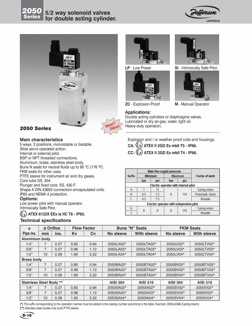
2050 Series
D-16
Applications:Double acting cylinders or diaphragms valves.Lubricated or dry air-gas, water, light oil.Heavy-duty operation.
Main characteristics5 ways, 2 positions, monostable or bistable.Slide servo-operated action.Internal or external pilot.BSP or NPT threaded connections.Aluminium, brass, stainless steel body.Buna N seals for neutral fluids up to 80 °C (176 °F).FKM seals for other uses.PTFE sleeve for instrument air and dry gases.Core tube SS. 304.Plunger and fixed core: SS. 430 F.Shape A DIN 43650 connection encapsulated coils.IP65 and NEMA 4 protection.Options:Low power pilot with manual operator.Intrinsically Safe Pilot.
ATEX 6122X EEx ia IIC T6 - IP65.Technical specifications
ø Pipe ins.
ø Orifice Flow Factor Buna “N” Seals FKM Sealsmm ins. Kv Cv No sleeve With sleeve No sleeve With sleeve
Aluminium body1/4” 7 0.27 0.80 0.94 2050LA02* 2050LTA02* 2050LV02* 2050LTV02*3/8” 7 0.27 0.96 1.12 2050LA03* 2050LTA03* 2050LV03* 2050LTV03*1/2” 10 0.39 1.90 2.22 2050LA04* 2050LTA04* 2050LV04* 2050LTV04*
Brass body1/4” 7 0.27 0.80 0.94 2050BA02* 2050BTA02* 2050BV02* 2050BTV02*3/8” 7 0.27 0.96 1.12 2050BA03* 2050BTA03* 2050BV03* 2050BTV03*1/2” 10 0.39 1.90 2.22 2050BA04* 2050BTA04* 2050BV04* 2050BTV04*
(*) The suffix corresponding to the operation manner must be added to the catalog number according to the table, Example: 2050LA02A (Spring return).(**) Stainless steel bodies only build PTFE sleeve.
SuffixMain line supply pressure
Forms of workMínimum Máximumbar psi bar psi
Electric operator with internal pilotA 1 15
8 116Spring return
B 0.5 7.5 Pneumatic returnC 0.5 7.5 Bistable
Electric operator with independent pilotG 0 0 8 116 Spring returnI Bistable
LP - Low Power SI - Intrinsically Safe Pilot.
ZC - Explosion Proof M - Manual Operator
Stainless Steel Body ** AISI 304 AISI 316 AISI 304 AISI 3161/4” 7 0.27 0.80 0.94 2050SA02* 2050IA02* 2050SV02* 2050IV02*3/8” 7 0.27 0.96 1.12 2050SA03* 2050IA03* 2050SV03* 2050IV03*1/2” 10 0.39 1.90 2.22 2050SA04* 2050IA04* 2050SV04* 2050IV04*
Explosion and / or weather proof coils and housings. CA: ATEX II 2GD Ex mbll T5 - IP66.
CC: ATEX II 2GD Ex mbll T4 - IP66.
2050Series
5/2 way solenoid valvesfor double acting cylinder.
New!! ¡New!
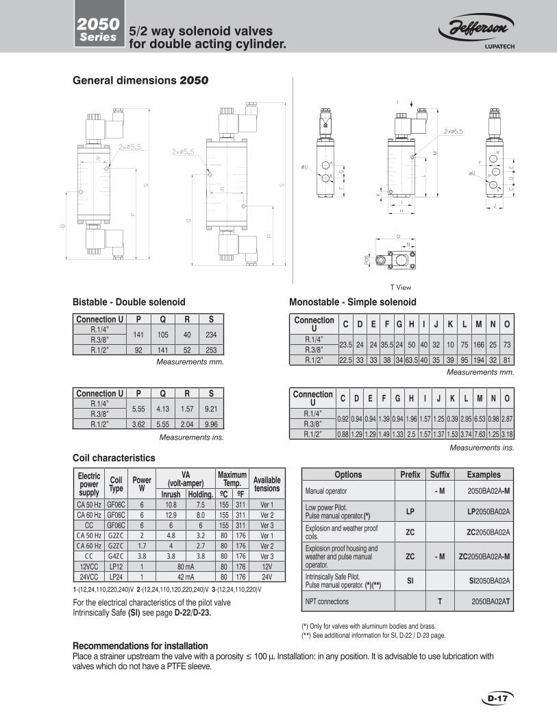
2050Series 5/2 way solenoid valves
for double acting cylinder.
D-17
General dimensions 2050
Recommendations for installationPlace a strainer upstream the valve with a porosity ≤ 100 μ. Installation: in any position. It is advisable to use lubrication with valves which do not have a PTFE sleeve.
Options Prefix Suffix Examples
Manual operator - M 2050BA02A-M
Low power Pilot.Pulse manual operator.(*) LP LP2050BA02A
Explosion and weather proof coils. ZC ZC2050BA02A
Explosion proof housing andweather and pulse manual operator.
ZC - M ZC2050BA02A-M
Intrinsically Safe Pilot.Pulse manual operator. (*)(**) SI SI2050BA02A
NPT connections T 2050BA02AT
Coil characteristics
Connection U C D E F G H I J K L M N O
R.1/4” 23.5 24 24 35.5 24 50 40 32 10 75 166 25 73R.3/8”R.1/2” 22.5 33 33 38 34 63.5 40 35 39 95 194 32 81
Measurements mm.
Connection U C D E F G H I J K L M N O
R.1/4” 0.92 0.94 0.94 1.39 0.94 1.96 1.57 1.25 0.39 2.95 6.53 0.98 2.87R.3/8”R.1/2” 0.88 1.29 1.29 1.49 1.33 2.5 1.57 1.37 1.53 3.74 7.63 1.25 3.18
Measurements ins.
T View
Connection U P Q R SR.1/4” 141 105 40 234R.3/8”R.1/2” 92 141 52 253
Measurements ins.
Measurements mm.
Bistable - Double solenoid Monostable - Simple solenoid
Connection U P Q R SR.1/4” 5.55 4.13 1.57 9.21R.3/8”R.1/2” 3.62 5.55 2.04 9.96
(*) Only for valves with aluminum bodies and brass.(**) See additional information for SI, D-22 / D-23 page.
Electricpowersupply
CoilType
Power W
VA (volt-amper)
MaximumTemp. Available
tensionsInrush Holding. ºC ºF
CA 50 Hz GF06C 6 10.8 7.5 155 311 Ver 1CA 60 Hz GF06C 6 12.9 8.0 155 311 Ver 2
CC GF06C 6 6 6 155 311 Ver 3CA 50 Hz G2ZC 2 4.8 3.2 80 176 Ver 1CA 60 Hz G2ZC 1.7 4 2.7 80 176 Ver 2
CC G4ZC 3.8 3.8 3.8 80 176 Ver 312VCC LP12 1 80 mA 80 176 12V24VCC LP24 1 42 mA 80 176 24V
1-(12,24,110,220,240)V 2-(12,24,110,120,220,240)V 3-(12,24,110,220)V
For the electrical characteristics of the pilot valveIntrinsically Safe (SI) see page D-22/D-23.

2051Series
3/2 way solenoid valvesfor single acting cylinder.
2051 Series
D-18
Applications:Single acting cylinders or diaphragms valves.Lubricated or dry air-gas, water, light oil.Heavy-duty operation.
Main characteristics3 way, 2 position, normally open, or normally closed.Slide servo-operated action.Internal or external pilot: pneumatic or electropneumatic.BSP or NPT threaded connections.Aluminium, brass, stainless steel body.Buna N seals for neutral fluids up to 80 °C (176 °F).FKM seals for other uses.PTFE sleeve for instrument air and dry gases.Shape A DIN 43650 connection encapsulated coils.IP65 and NEMA 4 protection.Options:Low power pilot with manual operator.Intrinsically Safe Pilot.
ATEX 6122X EEx ia IIC T6 - IP65.
Technical specificationsø
Connectionø Orifice Flow Factor Buna “N” Seals FKM Seals
mm ins. Kv Cv No sleeve With sleeve No sleeve With sleeveAluminium body
1/4” 7 0.27 0.80 0.94 2051LA02* 2051LTA02* 2051LV02* 2051LTV02*3/8” 7 0.27 0.96 1.12 2051LA03* 2051LTA03* 2051LV03* 2051LTV03*1/2” 10 0.39 1.90 2.22 2051LA04* 2051LTA04* 2051LV04* 2051LTV04*
Brass body1/4” 7 0.27 0.80 0.94 2051BA02* 2051BTA02* 2051BV02* 2051BTV02*3/8” 7 0.27 0.96 1.12 2051BA03* 2051BTA03* 2051BV03* 2051BTV03*1/2” 10 0.39 1.90 2.22 2051BA04* 2051BTA04* 2051BV04* 2051BTV04*
SuffixMain line supply pressure
Forms of workMinimum Maximumbar psi bar psi
Electric operator with internal pilotA 1 15
10 150
N.C. Spring returnB 0.5 7.5 N.C. Pneumatic returnC 0.5 7.5 BistableG 1 15 N.O. Spring returnH 0.5 7.5 N.O. Pneumatic return
Electric operator with independent pilotK
0 0 10 150N.O. Spring return
N N.O. Spring returnM Bistable
(*) The suffix corresponding to the operation manner must be added to the catalog number according to the table, Example: 2051LA02A (NC Spring return).(**) Stainless steel bodies only build PTFE sleeve.
Stainless Steel Body ** AISI 304 AISI 316 AISI 304 AISI 3161/4” 7 0.27 0.80 0.94 2051SA02* 2051IA02* 2051SV02* 2051IV02*3/8” 7 0.27 0.96 1.12 2051SA03* 2051IA03* 2051SV03* 2051IV03*1/2” 10 0.39 1.90 2.22 2051SA04* 2051IA04* 2051SV04* 2051IV04*
Explosion and / or weather proof coils and housings. CA: ATEX II 2GD Ex mbll T5 - IP66.
CC: ATEX II 2GD Ex mbll T4 - IP66.
LP - Low Power SI - Intrinsically Safe Pilot.
ZC - Explosion Proof M - Manual Operator
New!! ¡New!

2051Series 3/2 way solenoid valves
for single acting cylinder.
D-19
General dimensions 2051
Recommendations for installationPlace a strainer upstream the valve with a porosity ≤ 100 μ. Installation: in any position. It is advisable to use lubrication with valves which do not have a PTFE sleeve.
Coil characteristics
Measurements mm.
Measurements ins.Measurements ins.
Measurements mm.
Bistable - Double solenoid Monostable - Simple solenoid
Opciones Prefijo Sufijo Ejemplos
Manual operator bistable. - M 2051BA02A-M
Low power Pilot.Pulse manual operator. (*) LP LP2051BA02A
Explosion and weather proof coils. ZC ZC2051BA02A
Explosion proof housing andweather and pulse manual operator.
ZC - M ZC2051BA02A-M
Intrinsically Safe Pilot.Pulse manual operator. (*)(**) SI SI2051BA02A
NPT connections. T 2051BA02AT
Connection U B C D E F G H I J K LR.1/4”
11 24 126 22 23 36 40 50 32 25 73R.3/8”R.1/2” 15 31 145 31 31 9 52 63.5 35 32 79
Connection U M N O PR.1/4”
110 22 40 220R.3/8”R.1/2” 123 30 52 246
Connection U M N O PR.1/4”
4.33 0.86 1.57 8.66R.3/8”R.1/2” 4.84 1.18 2.04 9.68
Connection U B C D E F G H I J K LR.1/4”
0.43 0.94 4.96 0.86 0.90 1.41 1.57 1.96 1.25 0.98 2.87R.3/8”R.1/2” 0.59 1.22 5.70 1.22 1.22 0.35 2.04 2.5 1.37 1.25 3.11
(*) Only for valves with aluminum bodies and brass.(**) See additional information for SI, D-22 / D-23 page.
Electricpowersupply
CoilType
Power W
VA (volt-amper)
MaximumTemp. Available
tensionsInrush Holding. ºC ºF
CA 50 Hz GF06C 6 10.8 7.5 155 311 Ver 1CA 60 Hz GF06C 6 12.9 8.0 155 311 Ver 2
CC GF06C 6 6 6 155 311 Ver 3CA 50 Hz G2ZC 2 4.8 3.2 80 176 Ver 1CA 60 Hz G2ZC 1.7 4 2.7 80 176 Ver 2
CC G4ZC 3.8 3.8 3.8 80 176 Ver 312VCC LP12 1 80 mA 80 176 12V24VCC LP24 1 42 mA 80 176 24V
1-(12,24,110,220,240)V 2-(12,24,110,120,220,240)V 3-(12,24,110,220)V
For the electrical characteristics of the pilot valveIntrinsically Safe (SI) see page D-22/D-23.
T View
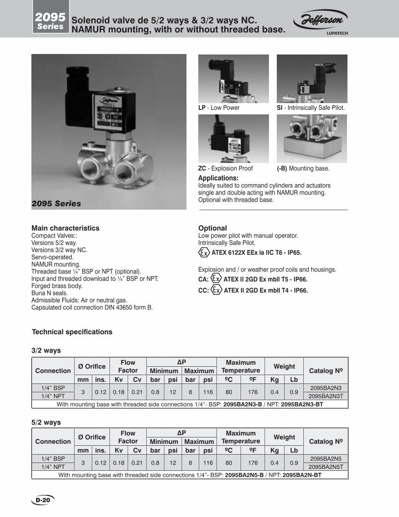
2095Series
Solenoid valve de 5/2 ways & 3/2 ways NC.NAMUR mounting, with or without threaded base.
2095 Series
D-20
Applications:Ideally suited to command cylinders and actuatorssingle and double acting with NAMUR mounting.Optional with threaded base.
Main characteristicsCompact Valves::Versions 5/2 way.Versions 3/2 way NC.Servo-operated.NAMUR mounting.Threaded base ¼” BSP or NPT (optional).Input and threaded download to ¼” BSP or NPT.Forged brass body.Buna N seals.Admissible Fluids: Air or neutral gas.Capsulated coil connection DIN 43650 form B.
Technical specifications
OptionalLow power pilot with manual operator.Intrinsically Safe Pilot.
ATEX 6122X EEx ia IIC T6 - IP65.
Explosion and / or weather proof coils and housings. CA: ATEX II 2GD Ex mbll T5 - IP66.
CC: ATEX II 2GD Ex mbll T4 - IP66.
ConnectionØ Orifice Flow
FactorΔP Maximum
Temperature WeightCatalog NºMinimum Maximum
mm ins. Kv Cv bar psi bar psi ºC ºF Kg Lb1/4” BSP
3 0.12 0.18 0.21 0.8 12 8 116 80 176 0.4 0.92095BA2N3
1/4” NPT 2095BA2N3TWith mounting base with threaded side connections 1/4”- BSP: 2095BA2N3-B / NPT: 2095BA2N3-BT
3/2 ways
5/2 ways
ConnectionØ Orifice Flow
FactorΔP Maximum
Temperature WeightCatalog NºMinimum Maximum
mm ins. Kv Cv bar psi bar psi ºC ºF Kg Lb1/4” BSP
3 0.12 0.18 0.21 0.8 12 8 116 80 176 0.4 0.92095BA2N5
1/4” NPT 2095BA2N5TWith mounting base with threaded side connections 1/4”- BSP: 2095BA2N5-B / NPT: 2095BA2N-BT
LP - Low Power SI - Intrinsically Safe Pilot.
ZC - Explosion Proof (-B) Mounting base.
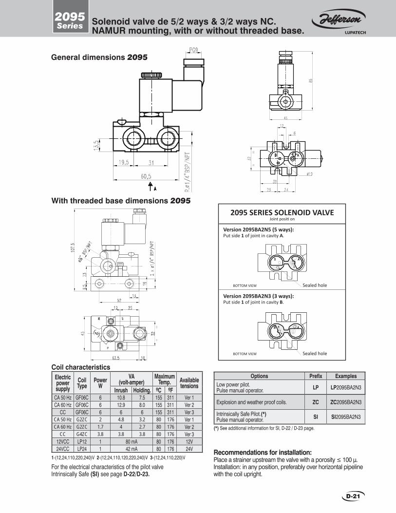
2095Series Solenoid valve de 5/2 ways & 3/2 ways NC.
NAMUR mounting, with or without threaded base.
D-21
General dimensions 2095
Recommendations for installation:Place a strainer upstream the valve with a porosity ≤ 100 μ. Installation: in any position, preferably over horizontal pipeline with the coil upright.
Options Prefix ExamplesLow power pilot.Pulse manual operator. LP LP2095BA2N3
Explosion and weather proof coils. ZC ZC2095BA2N3
Intrinsically Safe Pilot.(*)Pulse manual operator. SI SI2095BA2N3
With threaded base dimensions 2095
Version 2095BA2N5 (5 ways):Put side 1 of joint in cavity A.
Version 2095BA2N3 (3 ways): Put side 1 of joint in cavity B.
Sealed hole
Sealed hole
BOTTOM VIEW
BOTTOM VIEW
2095 SERIES SOLENOID VALVEJoint positi on
Electricpowersupply
CoilType
Power W
VA (volt-amper)
MaximumTemp. Available
tensionsInrush Holding. ºC ºF
CA 50 Hz GF06C 6 10.8 7.5 155 311 Ver 1CA 60 Hz GF06C 6 12.9 8.0 155 311 Ver 2
CC GF06C 6 6 6 155 311 Ver 3CA 50 Hz G2ZC 2 4.8 3.2 80 176 Ver 1CA 60 Hz G2ZC 1.7 4 2.7 80 176 Ver 2
CC G4ZC 3.8 3.8 3.8 80 176 Ver 312VCC LP12 1 80 mA 80 176 12V24VCC LP24 1 42 mA 80 176 24V
Coil characteristics
1-(12,24,110,220,240)V 2-(12,24,110,120,220,240)V 3-(12,24,110,220)V
For the electrical characteristics of the pilot valveIntrinsically Safe (SI) see page D-22/D-23.
(*) See additional information for SI, D-22 / D-23 page.
SISeries
Intrinsically Safe Pilot.Additional information.
A mínimum amount of energy is needed to produce the ignition of a combustible and oxidizing blend. The Intrinsically safe is a preventive method applied to feeding energy of a certain device, in this case a solenoid valve, preventing to reach this value, both in normal conditions and fail situations.The usage of intrinsically safe solenoid valves, results in many considerable advantages towards systems in which other explosion containing methods are applied, therefore using the intrinsically safe option will not produce spark as standard explosion proof contained methods.The intrinsically safe valve is not enough to accomplish all the safety requirements, it also has to be fed from a electrical source delivered from an associated device, located outside the danger area, this assures that inside the explosive area even in presence of a shortcut the energy values will maintain below the deflagration level.
For a better understanding we should introduce some concepts of the standard ANSI/ISA-RP12.06.01-2003.Intrinsically safe device: Is any device in which all its circuits are intrinsically safe. They can be active devices that generate electrical energy restricted to a 1.5 V, current of 100mA and a power smaller than 25mW or passives that do not dissipate energy beyond 1.3W.
Associated device: Any device in which their circuits aren´t necessarily intrinsically safe and are used to maintain intrinsically safe within the area classified as explosive.
Intrinsically safe system: it consist of a device associated installed within a Secure area (or inside an area classified as Division 2 / zone 2), wherein connects by wire to an intrinsically safe device installed within an area classified as Division 1 (zone 1 or zone 0).
Intrinsically safe barriers: These are the most commonly used associated devices, Connected between the intrinsically safe instrument and its controller. The main propose is restricting the energy sent towards the area under normal operation condition or under failure.
There are two types:Passive Intrinsically safe barriers: employing Zener diodes to limit the tension near the classified area, in addition of resistors and fuses to restrict the flow of electricity. In order to use this kind of barrier it must exists a common equipotential ground system separated from the factory one. Besides the installed device in the danger area must be isolated from other kinds of grounds.
Galvanic barriers it´s the best option, when there is no available equipotential ground system or the field devices don´t gather to it, because these provides a floating supply and the same signal to the transmitter, thanks to an isolating transformer.This kind of barrier provides a full electrical isolation between the inputs, the outputs, supply and immunity to the problems associated to ground connections of Zener barriers and their ability to realize any additional conditioning to the signal, making it more versatile and their application as a protection method easier and more reliable.
There are other kinds of devices associated that are not necessarily barriers of intrinsically safe, but they have energy limiting circuits similar to these barriers. For example a PLC that is not intrinsically safe by itself, has to be installed in a secure area, but has certain modules for inlet and outlet signals of intrinsically safe instruments.
When they are evaluated separately the I.S. instrument or device (instrument or electro valve) and the element associated of I.S. (security barrier), the electrical values called identity parameters, must be compatible, depending on it the correct combination when they are assembled.
The criteria employed that takes place in such combinations is that voltage and electricity that could be absorbed from a I.S. valve, considering failure conditions, must be equal or bigger to the voltage and electricity provided from the IS barrier.
In addition the capacity and maximum inductance including wiring that the I.S. instrument is capable to store without protection, must be equal or smaller to the capacity and inductance connected to the IS device associated.
Summary:Vi max ≥ V SuministratedIi max ≥ I Suministrated Li + L wire ≤ La (associated device) Ci + C wire ≤ Ca (associated device)Achieving these criteria, then these could be combined, the I.S. instrument or equipment with their associated I.S. device.

SISeries Intrinsically Safe Pilot.
Additional information.
Electrical characteristics of intrinsically safety pilot valve
For 24 VU nominal voltage 24 VDC U min 18 VDC P maximum power: 0,70 W.I deflagration: 55,5 mA Maximum current: I max: 37 mA (maximum current which may flow through the coil).C internal capacity: 0 Resistance at room temperature: +20 ºC = 580 Ω ± 7 %.Resistance at room temperature: -10 ºC ≤ 476 ΩResistance at room temperature: +50 ºC ≤ 690 Ω.Max. U (EEx source) at the circuit terminals: 28 V
For 12 VU nominal voltage 12 VDC U min 9 VDCP maximum power: 0,70 W.I deflagration: 111 mAMaximum current: I max: 74 mA (maximum current which may flow through the coil).C internal capacity: 0 Resistance at room temperature: +20 ºC = 146 Ω ± 7 %.Resistance at room temperature: -10 ºC ≤ 119 Ω.Resistance at room temperature: +50 ºC ≤ 174 Ω.Max. U (EEx source) at the circuit terminals: 18 V
• Maximum operating pressure: 7 bar.• Ambient temperature -10 º C to +50 º C• Compressed air Maximum temperature: + 50 ° C• Authorized Fluid: dry air, class 4, according to ISO 8573-1 (or inert gas)
• Maximum operating frequency: 2 Hz• Duty cycle 100% ED• Strictly observe polarities electrical connection.• Channel leaks outside the ATEX.• Other features: see catalog.
Operating Conditions

D-24
2024Series 5/2-way miniature valve.
Main characteristics For compressed air and other neutral gases.Forged brass body.Buna “N” seals and seats.BSP or NPT 1/4” threaded connections.Servo operated action.Shape A DIN 43650 connection encapsulated coilIP65 NEMA 4 protection.Maximum temperature: 80 °C.Options:•Energized coil indicator light.•Explosion and weather proof coils and housings.
2024 Series
General dimensions 2024F
G
C
Bø1/4”
A
E VIEW
D
E
I
Pg9
H
R3
B A
P
J K
E VIEW - Mounting details
S
R
Applications:•These valves control small double acting cylinder not larger than 4” in diameter.
A BøA C D E F G H I
Measurements: mm
R 1/4” 49 26 27 11 91 85 27 49 35
J K
40 49
A BøA C D E F G H I
Measurements: ins.
R 1/4” 1.92 1.02 1.06 0.43 3.58 3.34 1.06 1.92 1.37
J K
1.57 1.92
Contact our manufacturing plant forin format ion on ava i lab le models
Recommendations for installationPlace a strainer upstream the valve with a porosity ≤ 100µ. It is advisable to use lubrication with compressed air. Installation: in any position. Preferably over horizontal pipeline with the coil upright.
1.75
Ø Orifi ce
Flow factor
Technical specifi cations
2024BA2T2024BA2T-M
mm ins. Kv Cv
∆p Minimum Maximum
psibar psibar kg
Weight
Lb
Catalog Nº
0.08 0.8 10 0.7
Ø Pipe ins.
1/4” 2024BA22024BA2-M
BSP NPT
ManualOperator
NoYes
0.07 120.09 150 1.55
1 - ( 2 4 , 1 1 0 , 2 2 0 ) V 2 - ( 2 4 , 1 1 0 , 1 2 0 , 2 4 0 ) V 3 - ( 1 2 , 2 4 , 1 1 0 , 2 2 0 ) V
Coil characteristicsElectricpowersupply
AC 50 Hz
AC 60 Hz
DC
Availabletensions
MaximumtemperatureCoil
typePower
WVA (volt-amper)
Inrush MF11CMH11CMF13CMH13CMH19C
1111131319
11223
Holding 0C 0F4040454519
2222272719
155 180 155 180 180
311356311356356
OptionsWater, weather and saline corrosion proof coils.
Explosion and weather proof coils.
Weatherproof housing
Explosion and weather proof housing.
NPT connections
Prefi x
YC
ZC
YZ
Examples Suffi x
YC2024BA2
ZC2024BA2
Y2024BA2Z2024BA2
2024BA2TT Energized coil indicator light See coils.

E-1
1310 1311 1360
1369 2073 1372
Valves and Devices for Special Service
2094 1398 “UC”
1372 Series E-11
2073 SeriesE-10
1369 SeriesE-8 / E-9
1360 SeriesE-6 / E-7
1311 SeriesE-4 / E-5
1310 Series Pneumatically operated globe valves.
Pneumatically operated diaphragm valves.
Solenoid valvesfor corrosive fl uids.
Manual reset devicefor solenoid valves
Solenoid valvesfor dust collector systems.
Pneumatic operator.
Solenoid valvesfor CNG (VNG).
Pulse operated solenoid unit.
Digital condensation removal timer.
Solenoid valves forcryogenic fl uids.
Power control.
E-2 / E-3
E-12 / E-13
Pages
2094 Series
1370 Series
1398 Series
“UC” Series
“CP” Series
E-14
E-15
E-16 / E-17
E-18
To request a technical bulletin for models that are not included in this catalog, please contact JEFFERSON at:
New productsNEW SOLENOID VALVE MODELS
1397Series
• For Natural Gas Compressors at CNG gas stations.• For CNG Automotive Use.

E-2
Globe valves operated by pneumatic or hydraulic action.
1310Series
Main characteristicsNormally closed or normally open.Direct acting. Operated by double acting pneumatic or hydraulic cylinder (air, water, light oils).Body: bronze, carbon steel, stainless steel, etc.BSP or NPT threaded or fl anged connections.Buna “N”, PTFE, stainless steel seats.
Minimum auxiliary pressure: 1.5 bar.5-Way, 2 or 3 position pilot valve.DIN 43650 connection encapsulated coil.IP65 and NEMA 4 protection.Standard constructions to be used with water, air, light oils, other neutral liquids or steam up to 200 °C.
1310 Series
Applications: These are used when there are no solenoid valvesavailable due to size, pressure, working temperature, type of fl uid or special service conditions (explosiveareas, corrosive fl uids, etc.)
CERTIFIED QUALITY SYSTEM
Ø Pipe ins.
3/4”1”
1.1/2”2”
2.1/2”3”4”6”8”
Ø Orifi ce
Catalog Nº according to body and seat material.
FlowFactor
Technical specifi cations
192632387676100150200
61115236685
150320600
1310BA06D31310BA08D31310BA12D31310BA16D41310BA20D41310BA24D6
------
202010102
1024
3.5
1310SS06D31310SS08D31310SS12D31310SS16D41310SS20D41310SS24D6
1310SS32BD61310SS48BD8
1310SS64BD10
1310AS06D31310AS08D31310AS12D31310AS16D41310AS20D41310AS24D6
1310AS32BD61310AS48BD8
1310AS64BD10
mm ins. Kv Cv bar psi
∆p maximum
(*) For PTFE seats change A for T. Example: 1310BT06D3Note: Maximum temp.: with PTFE or stainless steel seat 200 °C - with Acrylo-nitrile N seat 80 °C. Maximum pressure: Maximum pressures are determined considering an auxiliary pressure of 5 bar.
ø Cylinder
mm ins.
3”
4”
6”
8”10”
Body materialBronze Carbon Steel AISI304
Seat materialBuna N (*) S.S. AISI304
76.2
101.6
152.4
203.2254
0.751.021.261.52.992.993.945.917.87
71318277799
176374702
30030015015030
150306053

E-3
1310Series
Globe valves operatedby double acting pneumaticor hydraulic cylinder with solenoid pilot.
150157173180163163------
324149518989------
B C ø C1 Dø A99
108127152178191229279343
317335358394466466570673770
3/4”1”
1.1/2”2”
2.1/2”3”4”6”8”
E
100122139149224224------
D1
408426449485557557661764861
E1
117127165203216241292406495
Measurements: mm
5.906.186.817.086.416.41
------
1.261.611.922.003.503.50
------
B C ø C1 Dø A3.894.255.005.987.007.529.01
10.9813.50
12.4813.1814.0415.5118.3418.3422.4426.4930.31
3/4”1”
1.1/2”2”
2.1/2”3”4”6”8”
E3.934.805.475.868.818.81
------
D116.0616.7717.6719.0921.9221.9226.0230.0733.89
E14.605.006.497.998.509.48
11.4915.9819.48
Measurements: ins.
General dimensions
E1
øA CE
D1
FLANGEDTHREADED
øC1
D
B
Special constructions:Consult Jefferson.
Recommendations for installationPlace a strainer upstream the pilot valve with a porosity ≤ 50µ if the fl uid is gas, or not greater than 100µ if the fl uid is water. It is advisable that the air or other gas employed is lubricated.It is also recommended to place an adequate strainer on the main line to prevent suspended solid elements from settling on the valve seats, thus hindering a comple-te shutoff.Mounting: Preferably over horizontal pipeline with the operator upright.
Pilot solenoid valves (supplied)For 3, 4, 6” cylinders: 2024BA2 (2 positions) 1339BA2 (3 positions)For 6, 8, 10” cylinders: 1350BA2 (2 positions) 1339BA2 (3 positions)
1-(12,24,110,220,240)V 2-(12,24,110,120,220,240)V 3-(12,24,110,220)V
Coil characteristicsElectricpowersupply
AC 50 Hz
AC 60 Hz
DC
Availabletensions
MaximumtemperatureCoil
typePower
WVA (volt-amper)
Inrush MF11CMH11CMF13CMH13CMH19C
1111131319
4040454519
2222272719
11223
Holding 0 C 0 F155 180 155 180 180
311356311356356
OptionsWater, weather and saline corrosion proof coils. Explosion and weather proof coils.
Weather proof housing
Explosion and weather proof housing.NPT connectionsFlanged connections
Prefi x
YC
ZC
Y
Z
Examples Suffi xYC1310BT12D3
ZC1310BT12D3
Y1310BT12D3
Z1310BT12D3
1310BT12TD31310BT12BD3
TB
Energized coil indicator light See coils
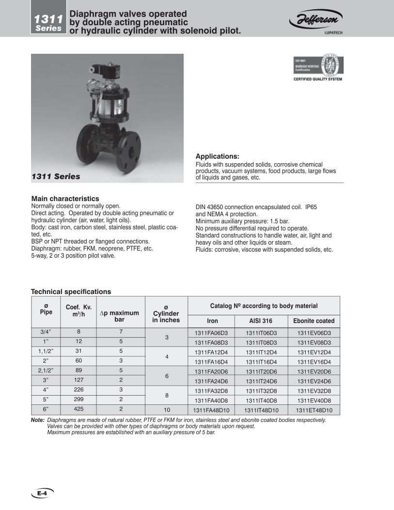
E-4
1311Series
Diaphragm valves operatedby double acting pneumatic or hydraulic cylinder with solenoid pilot.
Main characteristicsNormally closed or normally open.Direct acting. Operated by double acting pneumatic or hydraulic cylinder (air, water, light oils).Body: cast iron, carbon steel, stainless steel, plastic coa-ted, etc.BSP or NPT threaded or fl anged connections.Diaphragm: rubber, FKM, neoprene, PTFE, etc.5-way, 2 or 3 position pilot valve.
DIN 43650 connection encapsulated coil. IP65 and NEMA 4 protection.Minimum auxiliary pressure: 1.5 bar.No pressure differential required to operate.Standard constructions to handle water, air, light and heavy oils and other liquids or steam.Fluids: corrosive, viscose with suspended solids, etc.
1311 Series
Fluids with suspended solids, corrosive chemical products, vacuum systems, food products, large fl ows of liquids and gases, etc.
Applications:
CERTIFIED QUALITY SYSTEM
Technical specifi cations
Note: Diaphragms are made of natural rubber, PTFE or FKM for iron, stainless steel and ebonite coated bodies respectively. Valves can be provided with other types of diaphragms or body materials upon request. Maximum pressures are established with an auxiliary pressure of 5 bar.
Coef. Kv.m3/h
3/4”
1”
1,1/2”
2”
2,1/2”
3”
4”
5”
6”
8
12
31
60
89
127
226
299
425
7
5
5
3
5
2
3
2
2
3
4
6
8
10
1311FA06D3
1311FA08D3
1311FA12D4
1311FA16D4
1311FA20D6
1311FA24D6
1311FA32D8
1311FA40D8
1311FA48D10
1311IT06D3
1311IT08D3
1311IT12D4
1311IT16D4
1311IT20D6
1311IT24D6
1311IT32D8
1311IT40D8
1311IT48D10
1311EV06D3
1311EV08D3
1311EV12D4
1311EV16D4
1311EV20D6
1311EV24D6
1311EV32D8
1311EV40D8
1311ET48D10
AISI 316Iron Ebonite coated
Catalog Nº according to body materialø Pipe ∆p maximum
bar
ø Cylinderin inches

E-5
1311Series
Diaphragm valves operatedby double acting pneumatic or hydraulic cylinder with solenoid pilot.
125125125145145200200270330330
192129374348--------
B C ø C1 Dø A99
108127152178191229279343406
195215265315340390500660880
1000
3/4”1”
1.1/2”2”
2.1/2”3”4”6”8”
10”
E
100122139149224224--------
D1
275295345395420470580740960
1080
E1
117127160190216254305406521635
Measurements: mm
General dimensions
E1
øA
C
E
D1
FLANGEDTHREADED
øC1
D
Recommendations for installationPlace a strainer upstream the pilot valve with a porosity ≤ 50µ if the fl uid is gas and not greater than 100µ if the fl uid is water. It is advisable that air or other gas employed is lubricated.It is advisable to place the valve over horizontal pipeline with the operator upright.
Pilot solenoid valvesWith 3, 4, 6” cylinders: 2024BA2 (2 positions) 1339BA2 (3 positions)With 6, 8, 10” cylinders: 1350BA2 (2 positions) 1339BA2 (3 positions)
4.924.924.925.705.707.877.877.87
12.9912.99
0.740.821.141.451.691.89
--------
B C ø C1 Dø A3.894.25
55.987.007.529.01
10.9813.5015.98
7.678.46
10.4312.4013.3815.3519.6825.9834.6439.37
3/4”1”
1.1/2”2”
2.1/2”3”4”6”8”
10”
E3.934.805.475.868.818.81
--------
D110.8211.6113.5815.5516.5318.5022.8329.1337.7942.52
E14.60
56.297.488.5010
12.0015.9820.51
25
Measurements: ins.
1-(12,24,110,220,240)V 2-(12,24,110,120,220,240)V 3-(12,24,110,220)V
Coil characteristicsElectricpowersupply
AC 50 Hz
AC 60 Hz
DC
Availabletensions
MaximumtemperatureCoil
typePower
WVA (volt-amper)
Inrush MF11CMH11CMF13CMH13CMH19C
1111131319
4040454519
2222272719
11223
Holding 0C 0F155 180 155 180 180
311356311356356
B
OptionsWater, weather and saline corrosion proof coils. Explosion and weather proof coils.
Weather proof housing
Explosion and weather proof housing.NPT connectionsFlanged connections
Prefi x YC
ZC
Y
Z
Examples Suffi x
TB
Energized coil indicator light See coils
YC1311FA12D3
ZC1311FA12D3
Y1311FA12D3
Z1311FA12D3
1311FA12TD31311FA12BD3

E-6
1360Series
2 way solenoid valvesfor corrosive fl uids.
Main characteristicsAcrylic, PVC, PTFE bodies.FKM seals and diaphragms.Shielded core. Solenoid parts totally isolatedfrom the fl uid.Shape A DIN 43650 connection encapsulated coil.IP65 and NEMA 4 protection.Absence of galvanic electrolysis.No contamination of the fl uid handled.
Options:•Energized coil indicator light.•Explosion and weather proof coils and housings.
1360 TV4 1360 TV2
2.25
ø Orifi ce
Flow factor
Technical specifi cations
mm ins. Kv Cv
Max. pressure Imput Output
psibar psibar kg
Weight
LbCatalog
Nº
0.13 1 0.5
ø Pipe Figure
Nº
1/4”
3/8”
1/2”
1/4”
3/8”
1/2”
1360AV2
1360PV31360PV4
1360TV21360TV31360TV4
7
2.25
7
1 4
1
4
2
0.5
2
1
2
1
2
0.4
0.8
0.4
0.8
°C
Maximumtemperature
°F
Acrylic body
PVC body
PTFE body
Note: For Buna N diaphragms and seals, change letter “V” for “A” in the valve catalog number. Example: 1360TV4 turns into 1360TA4.
0.09
0.28
0.09
0.28
0.15
1.17
0.13
1
0.15
1.17
15
60
15
60
7.5
30
7.5
30
60
60
60
150
140
140
140
302
0.88
1.75
0.88
1.75
Contact our manufacturing plant forin format ion on ava i lab le models

1360Series
2 way solenoid valvesfor corrosive fl uids.
General dimensions
F
ø G
A
Pg9
B
C
ø A
D
E
Fig.1
A VIEW Mounting holes detail
2xW.3/16”
ø H
E VIEW Mounting holes detail
2xW.1/4”
ø H
Fig. 2
F
ø G
E VIEW
Pg9
D
E
ø A
I
ø1/8”
BC
Measurements: mm Measurements: ins.
Dimensions Fig. 1
Measurements: mm
Dimensions Fig. 2
Measurements: ins.
F
5785 27
B C D E
86 101/4
ø A ø G
40
ø H
27
F
2.243.35 1.06
B C D E
3.39 0.391/4
ø A ø G
1.57
ø H
1.06
F
5721 56
B C D E
85 271/2”3/8”
ø A ø G
60
ø H
35
F
2.240.83 2.20
B C D E
3.35 1.061/2”3/8”
ø A ø G
2.36
ø H
1.38
Resistance of materials in contact with the fl uidBodies Diaphragms, seals and seats
At low temperatures it is excellent for the most severe alkaline products,
mineral acids, salts and many other chemical products that corrode con-
ventional materials.
It is a hard and rigid resin. Weather, oxidation and light radiation proof.
Common acids and solvents resistant. It is corroded by strong acids: highly
concentrated oxidant acids (nitric, sulphuric, hydrochloric).
It is resistant to petroleum and its distillations, most mineral acids and aliphatic and aromatic hydrocarbons
which act as solvents to other elastomers. Not advisable for acetone
or halogenated hydrocarbons.
It is practically inert to all corrosive products. Atmospheric conditions do not affect it. It is not fl ammable and
has an exceptional low friction coeffi cient.
PVC AcrylicPTFE FKM
Special constructionsDiaphragms and seals: neoprene, ethylene propylene, etc.Vacuum Service.
Recommendations for installationPlace a strainer upstream the valve with a porosity ≤100µInstallation: in any position. Preferably over horizontalpipeline with the coil upright. Do not restrict the fl owdownstream with fi ttings or valves since this mayend up increasing the output pressure, thus hinderinga proper closure. If a fl ow control valve has to be installed, it must be located upstream the solenoid valve. In caseof using spray nozzles, make sure that the valve’s output pressure does not exceed the value shown in the table. Due to the mechanical properties and limitations of every material, the installation of a plastic body valve must be done very carefully in order to avoid distortion, especially while threading.
1-(12,24,110,220,240)V 2-(12,24,110,120,220,240)V
Coil characteristicsElectricpowersupply
AC 50 Hz
AC 60 Hz
Availabletensions
MaximumtemperatureCoil
typePower
WVA (volt-amper)
Inrush MF11CMH18CMF13CMH16C
11181316
40614548
22392729
1122
Holding 0C 0F155 180 155 180
311356311356
Ø Pipe ins.1/4”
3/8”-1/2”1/4”
3/8”-1/2”
OptionsWater, weather and saline corrosion proof coils.
Explosion and weather proof coils.
Weather proof housing
Explosion and weather proof housing.
NPT connections
Prefi x YC
ZC
YZ
Examples Suffi x
T
Energized coil indicator light See coils.
YC1360PV4
ZC1360PV4
ZC1360PV4
Z1360PV4
1360PV4T
E-7

1369Series
“Free-handle”manual reset safety device for solenoid valves.
Main characteristicsManual reset and automatic release.Reset with energized coil or without electric signal.The “free-handle” system sets the lever out ofoperation when the coil is de-energized (1369 version) or energized (1369B version).It is adaptable to most of our valve series.
1335-69 Series 1365-69 Series
Contact our manufacturing plant forin format ion on ava i lab le models
Technical specifi cations
Note: 1365 is also provided for normally open operation.
1327 1335 13901342
1/4”
3/8”
1/2”
3/4”
1”
1.1/2”
2”
1327BA402-69
--
--
--
--
--
--
--
1335BA3-69
1335BA4-69
1335BA6-69
--
--
--
--
--
1390BA4-69
1342BA06-69
1342BA08-69
1342BA12-69
1342BA16-69
1351LA1A-69
1351LA2A-69
1351LA3A-69
--
--
--
--
1365BA40U-69
1325BA3-69
1325BA4-69
1325BA6-69
--
--
--
1350LA1A-69
1350LA2A-69
1350LA3A-69
--
--
--
--
1351 13651325
1350
1369 version - Reset with electrical signal
1327BA402-69B
--
--
--
--
--
--
--
1335BA3-69B
1335BA4-69B
1335BA6-69B
--
--
--
--
--
1390BA4-69B
1342BA06-69B
1342BA08-69B
1342BA12-69B
1342BA16-69B
1351LA1A-69B
1351LA2A-69B
1351LA3A-69B
--
--
--
--
1365BA402-69B
1325BA3-69B
1325BA4-69B
1325BA6-69B
--
--
--
1350LA1A-69B
1350LA2A-69B
1350LA3A-69B
--
--
--
--
1369B version - Reset without electrical signal
ø Pipe ins.
1/4”
3/8”
1/2”
3/4”
1”
1.1/2”
2”
E-8

1369Series
“Free-handle”manual reset safety device for solenoid valves.
General dimensions
70 57A B C D
41 140E
104Measurements: mm
2.76 2.24A B C D
1.61 5.51E
4.09Measurements: ins.
B C
A
R. 85
DE
ø1/2”
B C
A
R. 85
DE
ø1/2”
1-(12,24,110,220,240)V 2-(12,24,110,120,220,240)V 3-(12,24,110,220)V
Coil characteristicsElectricpowersupply
AC 50 Hz
AC 60 Hz
DC
Availabletensions
MaximumtemperatureCoil
typePower
WVA (volt-amper)
Inrush MF11CMH11CMF13CMH13CMH19C
1111131319
4747575719
1818232319
11223
Holding 0 C 0 F155 180 155180 180
311356311356356
OptionsWater, weather and saline corrosion proof coils. Explosion and weather proof coils.Weather proof housing.Explosion and weather proof housing.NPT connections
Prefi x YC
ZC
Y
Z
Examples Suffi xYC1335BA3-69
ZC1335BA3-69
Y1335BA3-69
Z1335BA3-69
1335BA3T-69T Energized coil indicator light See coils.
Operation 1369 FOR NORMALLY CLOSED VALVES (N.C.)
1- Energized, unlatched.(Valve is closed)
2- Energized and latched manually, (Valve opens)
1369B FOR NORMALLY CLOSED VALVES (N.C.)
1- De-energized, unlatched.(Valve is closed)
2- De-energized and latched manually, (Valve opens)
3- Tripped due to signal in the coil, valve closes remains so after stopping.
3- Tripped due to lack of electric signal, valve closes and remains so, even
after the signal is restored.
E-9
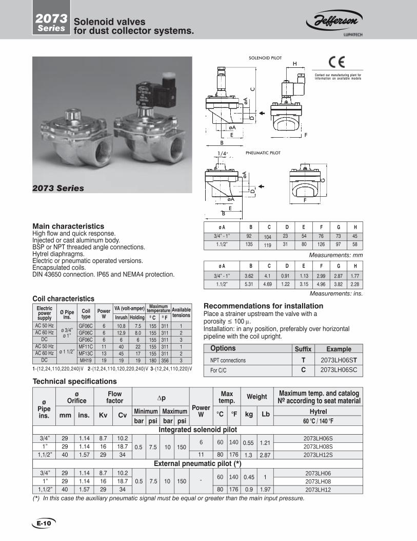
2073Series
Solenoid valves for dust collector systems.
EFøA
øA
D
G
PNEUMATIC PILOT1/4”
Main characteristicsHigh fl ow and quick response.Injected or cast aluminum body.BSP or NPT threaded angle connections.Hytrel diaphragms.Electric or pneumatic operated versions.Encapsulated coils.DIN 43650 connection. IP65 and NEMA4 protection.
SOLENOID PILOT
2073 Series
B
92135
104119
B C D Eø A2331
5480
3/4” - 1”1.1/2”
G7397
F76
126
Measurements: mm
H4558
F
H
DC
øA
øAE
B
3.625.31
4.14.69
B C D Eø A
0.911.22
1.133.15
3/4” - 1”1.1/2”
G
2.873.82
F
2.994.96
Measurements: ins.
H
1.772.28
Contact our manufacturing plant forin format ion on ava i lab le models
Power W Hytrel
60 °C / 140 °FCv
ø Pipe ins. mm ins. Kv
Maximum temp. and catalog Nº according to seat material
Flowfactor
ø Orifi ce
3/4”1”
1,1/2”
3/4”1”
1,1/2”
292940
8.71629
6
11
2073LH06S2073LH08S2073LH12S
8.71629
-292940
2073LH062073LH082073LH12
(*) In this case the auxiliary pneumatic signal must be equal or greater than the main input pressure.
Minimum Maximum
∆p
0.5
kg
Weight
Lb
0.55
1.3
0.45
0.9
Maxtemp.
°C °F
0.5
10
10
bar psi bar psi Integrated solenoid pilot
60
80
60
80
1.141.141.57
1.141.141.57
10.218.734
10.218.734
7.5
7.5
150
150
140
176
140
176
1.21
2.87
1
1.97
External pneumatic pilot (*)
OptionsNPT connections
For C/CTC
Example Suffi x2073LH06ST2073LH06SC1-(12,24,110,220,240)V 2-(12,24,110,120,220,240)V 3-(12,24,110,220)V
Coil characteristicsElectricpowersupply
Availabletensions
MaximumtemperatureCoil
typePower
WVA (volt-amper)
Inrush Holding 0 C 0 FØ Pipe
ins.
ø 3/4” ø 1”
AC 50 HzAC 60 Hz
DCAC 50 HzAC 60 Hz
DC
GF06CGF06CGF06CMF11CMF13CMH19
666
111319
155 155 155155 155 180
311311311311311356
10.812.9
6404519
7.58.06
221719
123123
ø 1 1/2”
Recommendations for installationPlace a strainer upstream the valve with aporosity ≤ 100 µ.Installation: in any position, preferably over horizontalpipeline with the coil upright.
E-10
Technical specifi cations

1372Series
Pneumaticoperator.
Main characteristicsOperates with pneumatic signal.Replaces the solenoid operator and can be adapted to some of the size M solenoid valve models.Normally closed and normally open.Seats: Buna N, FKM, etc.Minimum operating pressure: 1 bar.Maximum operating pressure: 10 bar.
Series that match with this deviceDirect acting: 1327 SeriesPilot operated: 1335 - 1342 - 1390 Series.
For N.C. models, the auxiliar minimum pressure is 1 bar.For N.O. models, the auxiliar minimum pressure equals the maximum pressure of the fl uid to be controlled plus 1 bar.
1335-72 Series1342-72 Series
General dimensions
ø B
ø A
Hexag. D
1342-72
1335-72
C
ø A
Measurements: mm
ø B Cø A31 30R 1/8”
Hexag. D32
Measurements: ins.
ø B Cø A1.22 1.18R 1/8”
Hexag. D1.26
E-11

2094Series
Solenoid valvesfor CNG (VNG).
Applications:Automatic safety shutoff for Compressed NaturalGas Systems, like CNG Dispensers, etc.
General description2094 series valves have been designed to handle high pressure fl uids such as gaseous fuels andoffer the customer the ultimate in performance, resistance and effi ciency under hard working conditions.In addition, the piston system allows perfect opening and shutoff through an 8 mm passage, by means of a pilotorifi ce suited for high pressure.
Main characteristicsNormally closed.Servo-operated action.Brass body.Inoxidable piston and Delrin seats.NPT threaded connection.Core tube SS. 304 and 316.Plunger and fi xed core: SS. 430 F.Shading coil: copper, silver or aluminum.Housing: Integrated explosion and weather proof according to IEC 79-1 “d”.
2094 Series
ATEX - Directive 94 / 9II 2G Ex d IIB T3
CERTIFIED QUALITY SYSTEM
CatalogNO
Cv
ø Pipe ins. mm ins. Kv
Flowfactor
ø Orifi ce
Technical specifi cations
1/4”3/8”1/2”
81.11.51.5
0C
Working temperature
barMaximum
psibarMinimum
psi
Operating pressure differential
1 250 -20 176Z2094RBD2Z2094RBD3Z2094RBD4
Power W
11 13
50 Hz 60 Hz
15 3750
kg
Weight
Lb
0.311.291.761.76
2.3 5
New products NEW SOLENOID VALVE MODELS
• For Natural Gas Compressors at NGC gas stations. 1397 Series • For CNG Automotive Use. 2099 Series
To request a technical bulletin for models that are not included in this catalog, please contact JEFFERSON at
E-12
0F 0C 0FMaximumMinimum
-4 80

2094Series
Solenoid valvesfor CNG (VNG).
General dimensions 2094
Measurements: mm
62.5
75
øB øCøA D ER 1/4” NPTR 3/8” NPTR 1/2” NPT
82
82
52
52
80
80
133
133
F
32
32
G
Measurements: ins.
2.46
2.95
øB øCøA D ER 1/4” NPTR 3/8” NPTR 1/2” NPT
3.23
3.23
2.05
2.05
3.15
3.15
5.24
5.24
F
1.26
1.26
G
øC
øB
B
øA
D
øA
øR 1
/2” N
PT
E
F
(Out)
(In)P
G
Recommendations for installationPlace a strainer upstream the valve with a porosity ≤ 50 µ.Mounting: In any position, preferably over horizontal pipeline with the coil upright.
1 - ( 1 2 , 2 4 , 1 1 0 , 2 2 0 , 2 4 0 ) V 2 - ( 1 2 , 2 4 , 1 1 0 , 1 2 0 , 2 2 0 , 2 4 0 ) V
Coil characteristicsElectricpowersupply
AC 50 Hz
AC 60 Hz
Availabletensions
MaximumtemperatureCoil
typePower
WVA (volt-amper)
Inrush M11FM11HM13FM13H
11111313
40404545
22222727
1122
Holding 0C 0F155 180 155 180
311356311356
E-13
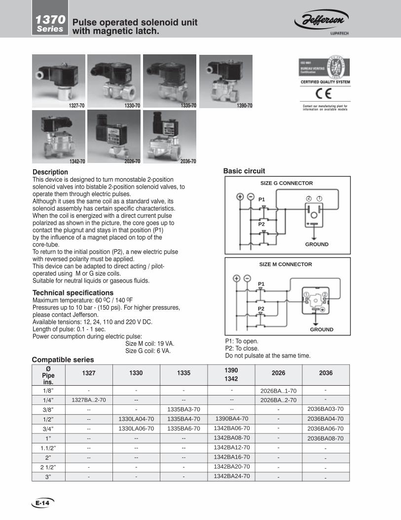
1370Series
Pulse operated solenoid unitwith magnetic latch.
1327-70 1330-70 1335-70
2026-701342-70
1390-70
2036-70
CERTIFIED QUALITY SYSTEM
Contact our manufacturing plant forin format ion on ava i lab le models
Technical specifi cationsMaximum temperature: 60 0C / 140 0F Pressures up to 10 bar - (150 psi). For higher pressures, please contact Jefferson.Available tensions: 12, 24, 110 and 220 V DC.Length of pulse: 0.1 - 1 sec.Power consumption during electric pulse: Size M coil: 19 VA. Size G coil: 6 VA.
DescriptionThis device is designed to turn monostable 2-position solenoid valves into bistable 2-position solenoid valves, to operate them through electric pulses.Although it uses the same coil as a standard valve, its solenoid assembly has certain specifi c characteristics.When the coil is energized with a direct current pulse polarized as shown in the picture, the core goes up to contact the plugnut and stays in that position (P1) by the infl uence of a magnet placed on top of the core-tube.To return to the initial position (P2), a new electric pulse with reversed polarity must be applied.This device can be adapted to direct acting / pilot-operated using M or G size coils.Suitable for neutral liquids or gaseous fl uids.
P1: To open.P2: To close.Do not pulsate at the same time.
SIZE M CONNECTOR
2 1
GROUND
GROUND
P1
P2
Basic circuit
P1
P2
SIZE G CONNECTOR
1327 1330 1335
1/8”1/4”3/8”1/2”3/4”1”
1.1/2”2”
2 1/2”3”
-
1327BA..2-70
--
--
--
--
--
--
-
-
----
1330LA04-701330LA06-70
--------
2026BA..1-702026BA..2-70
---
-
-
-
-
-
--
2036BA03-70
2036BA04-70
2036BA06-70
2036BA08-70
-
-
-
-
13901342
2026 2036Ø Pipe ins.
-----
1390BA4-701342BA06-701342BA08-701342BA12-701342BA16-701342BA20-701342BA24-70
---
1335BA3-701335BA4-701335BA6-70
--------
Compatible series
E-14

1398Series
Digital condensationremoval timer.
1398 Series
Applications:Automatic draining of filters, liquid separators, dryers, receivers, pipes and other compressed air system components.
CERTIFIED QUALITY SYSTEM
Contact our manufacturing plant forin format ion on ava i lab le models
General description•The Digital Condensation Removal Timer is a compact electronic device specially designed for pipe air condensation removal when matched with a solenoid valve.
•This digital timer is adaptable to any valve using a DIN type, 43650 – shape A coil.
•This device can by easy programmed by two press-keys and an LCD display.
Technical Specifi cationsSupply voltage: 12 - 115 VDC. 24 - 240 VAC.
Maximum current: 1 A.
Poles: 2 + Ground.
Time ranges: Off 0-99.59 min. On 0-59 sec
Time adjustment
1 - Press SET for 2 seconds.2 - Press ADJ to adjust ON time (sec.)3 - Press SET4 - Press ADJ to adjust OFF time ( min.)5 - Press SET
Reset press protected switch located above SET & ADJ keys.
Ambient temperature: -10 °C to +50 °C; (+14 °F to +122 °F).
Weight: 64 g; (2.3 oz.).
Protection: IP65 when plugged to a coil with a connector.
Insulation group: VDE 0110 1/89 - Class C.
Series that may be adapted to this deviceDirect acting: 1327Servo operated action: 1335 - 1342 - 1390.
E-15

UCSeries
Cryogenic service and liquid CO2solenoid valves.
1327-UC 1390-UC 1314-UC
Main characteristics1314, 1327 and 1390 Series with the suffi x “UC” solenoid valves are specially designed to control cryogenic fl ow. Cryogenic fl uids include liquid oxygen, liquid argon, liquid nitrogen and liquid CO2. All valves showing a UC suffi x are clean, and free from oil and moist.Temperature ranges:Cryogenic fl uids -200 °C to 50 °C (-328 °F to 122 °F).Liquid CO2 : -60 °C to 50 °C (-76 °F to 122 °F).
Construction MaterialsBody: Brass or bronze.Seals and seats: PTFE.Piston: 1314 Series: SS304 / 1390 Series: Brass.Core assembly and magnetic stop: AISI 430.Springs: 302.Shading coil: copper.
CERTIFIED QUALITY SYSTEM
Contact our manufacturing plant forin format ion on ava i lab le models
Technical specifi cations *Advise: when using direct current (DC), a 25% reduction on the maximum operating pressure differential is expected
(1) Connection pipe: Inside diam. cannot be larger than valve´s passage. The expansion will occur downstream, far away from valve. It prevents CO2 from freezing.
E-16
Normally Closedø
Pipeins.
ø Orifi ce
Flowfactor
∆p minimum
∆p * maximum
MinimumTemp.
MaximumTemp. Weight
Catalog Nºmm ins. Kv Cv bar psi bar psi C° F° C° F° kg Lb
1/4”3 0.12 0.26 0.30
0 010 150
-200 -328 50 122
0.5 1.1 1327BT302UC4 0.16 0.43 0.50 5 75 0.5 1.1 1327BT402UC6 0.24 0.8 0.94
0.1 1.5 15 2250.75 1.7 1390BBT2UC
3/8” 9 0.35 1.6 1.87 0.70 1.5 1390BBT3UC
1/2”12 0.47 2.35 2.75 0.96 2.1 1390BBT4UC19 0.75 4.5 5.27
0 0 7 105
4 8.9 1314BST04UC3/4” 19 0.75 6 7.02 4 8.9 1314BST06UC1” 26 1.02 10 11.7 4.9 10.9 1314BST08UC
1 1/2” 32 1.26 15 17.6 6.5 14.4 1314BST12UC2” 38 1.5 23 26.9 7.3 16.2 1314BST16UC
Normally Open
1/4”3 0.12 0.26 0.30
0 010 150
-200 -238 50 122
0.5 1.1 1327BT302INAUC4 0.16 0.43 0.50 5 75 0.5 1.1 1327BT402INAUC6 0.24 0.8 0.94
0.1 1.5 15 2250.75 1.7 1390BBT2INAUC
3/8” 9 0.35 1.6 1.87 0.70 1.5 1390BBT3INAUC1/2” 12 0.47 2.35 2.75 0.96 2.1 1390BBT4INAUC
Liquid CO2 service (1) Normally Closed
1/8”
1.25 0.5 0.05 0.06
0 0
100 1500
-60 -76 50 122
0.5 1.1 1327BT121UC1.75 0.07 0.09 0.11 35 525 0.5 1.1 1327BT171UC2.25 0.09 0.13 0.15 20 300 0.5 1.1 1327BT221UC3.00 0.12 0.26 0.30 10 150 0.5 1.1 1327BT301UC
Liquid CO2 service (1) Normally Open
1/8”
1.25 0.5 0.05 0.06
0 0
50 750
-60 -76 50 122
0.5 1.1 1327BT121INAUC1.75 0.07 0.09 0.11 20 300 0.5 1.1 1327BT171INAUC2.25 0.09 0.13 0.15 12 180 0.5 1.1 1327BT221INAUC3.00 0.12 0.26 0.30 10 150 0.5 1.1 1327BT301INAUC

UCSeries
Cryogenic service and liquid CO2solenoid valves.
E-17
1314 UC
General dimensions
Measurements: ins.
B CøA øD E F G øH I5.916.187.097.09
1.261.611.932.01
2.993.543.943.94
3.944.725.875.87
R 3/4”R 1”
R 1.1/2”R 2”
3.153.503.823.94
4.454.725.635.79
3.90 3.74
Measurements: mm
B CøA øD E F G øH I150157180180
32414951
7690
100100
100120149149
R 3/4”R 1”
R 1.1/2”R 2”
808997
100
113120143147
99 95
1327 UC
Coil characteristicsElectricpowersupply
AC 50 HzAC 60 Hz
DCAC 50 HzAC 60 Hz
DCAC 50 HzAC 60 Hz
DC
Availabletensions
MaximumtemperatureCoil
typePower
WVA (volt-amper)
Inrush MF11CMF13CMH19CMH18CMH16CMH19CSH28CSH30CSH48C
111319181619283048
404519614819
24126748
222719392919698048
123123123
Holding 0C 0F155 155 155180 180 180155155155
311311311356356356311311311
Version
1327UC1390UC
1327UC(CO2)
1314UC
1-(12,24,110,220,240)V 2-(12,24,110,120,220,240)V 3-(12,24,110,220)V
Recommendations for installationPlace a strainer with a porosity ≤ 100 µ upstream the valve. The valve input pressure must always be equal or greater than the output pressure.
1327UCMount the valve in any position, preferably over horizontal pipeline with the coil upright.
1314UC- 1390UCMount the valve only over horizontal pipeline with the coil upright.
FEB
CD
HPg9
E
G
RW 3/16”
E VIEW
Measurements: mm
80
B C D
57 22 10
E F G
85 27 20
H
Measurements: ins.3.15
B C D
2.24 0.87 0.39
E F G
3.35 1.06 0.79
H
H
CB
R 3/4”NF
Ø DøA
G
E
I
Measurements: mm
1/4” - 3/8”1/2”
Ø A B C D8585
2626
2222
E Ø F G5757
-55
52-
H15
15.5
I9799
Measurements: ins.
1/4” - 3/8”1/2”
Ø A B C D3.353.35
1.061.02
0.870.87
E Ø F G2.242.24
-2.17
2.05-
H0.590.61
I3.823.89
1390 UC
BC
E
HI
R 1/2”
PG9
DB
CE
D
G
H
R1/4”-3/8”
I
Ø F
R 1/8”

CPSeries Power control
t (sec)100 msec
20 % N.V.
N.V.
V
N.V. = NOMINAL VOLTAGE
General DescriptionThe CP is a solid state device placed on DIN –connection solenoid valves’ coil connectors to control valve power.The CP has two main functions: one is to induce a stronger than usual response at solenoid pull-in. The second is to reduce the solenoid power consumption during hold-in. The CP allows the input voltage directly to the coil for a fi xed single shot of 100 milliseconds. After that period the CP automatically decreases to 20 % of the input nominal voltage, and the power is decreased to 4 %.
• The CP is available in DIN 43650 / ISO 4400 shape “A“ connectors. • High-frequency operating cycles. • Saves energy by reducing overall consumption to nominal power. • Reduces temperature in long runs of energized coil. • Increases coil life considerably. • It is provided with a LED indicator light. • 3 m (9 ft) standard cable length.
Electrical Data
• Input Voltage: 12 to 24 VDC • Maximum input voltage tolerance 10 % • Ambient temperature range: -20° to 50 °C (4° to 122 °F) • Maximum output current: • Inrush (50 milliseconds): 8A • Holding: 1 A
CERTIFIED QUALITY SYSTEM
E-18

Technical information
F-5
F-4
F-2 / F-3
Pages
Fluids and materials compatibility table.
Recommendations for installation.
Problems and solutions.
Repair Kits. F-6 / F-7 / F-8
F-1

Fluids and materials compatibility
Table
F-2

Fluids and materials compatibility
Table
F-3
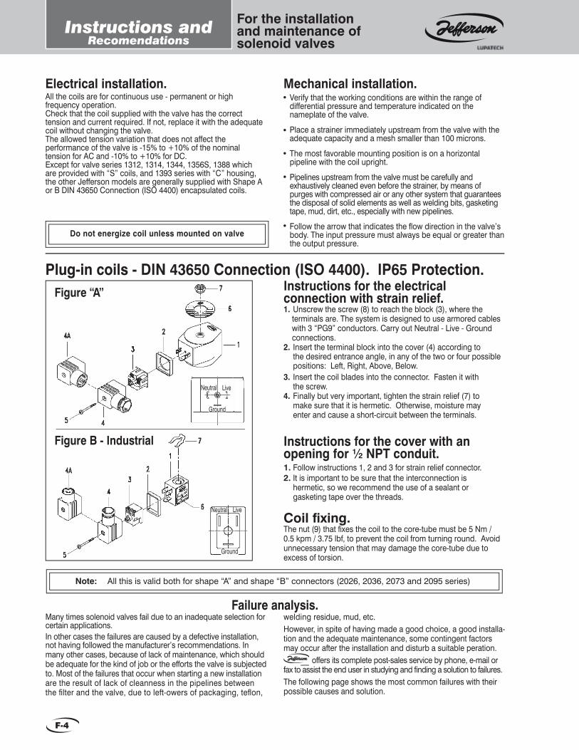
For the installationand maintenance ofsolenoid valves
Instructions andRecomendations
Electrical installation.All the coils are for continuous use - permanent or high frequency operation.Check that the coil supplied with the valve has the correct tension and current required. If not, replace it with the adequate coil without changing the valve.The allowed tension variation that does not affect the performance of the valve is -15% to +10% of the nominal tension for AC and -10% to +10% for DC.Except for valve series 1312, 1314, 1344, 1356S, 1388 which are provided with “S” coils, and 1393 series with “C” housing, the other Jefferson models are generally supplied with Shape A or B DIN 43650 Connection (ISO 4400) encapsulated coils.
Verify that the working conditions are within the range of differential pressure and temperature indicated on the nameplate of the valve.
Place a strainer immediately upstream from the valve with the adequate capacity and a mesh smaller than 100 microns.
The most favorable mounting position is on a horizontal pipeline with the coil upright.
Pipelines upstream from the valve must be carefully and exhaustively cleaned even before the strainer, by means of purges with compressed air or any other system that guarantees the disposal of solid elements as well as welding bits, gasketing tape, mud, dirt, etc., especially with new pipelines.
Follow the arrow that indicates the fl ow direction in the valve’s body. The input pressure must always be equal or greater than the output pressure.
Mechanical installation.
Do not energize coil unless mounted on valve
Plug-in coils - DIN 43650 Connection (ISO 4400). IP65 Protection.Instructions for the electrical connection with strain relief.1. Unscrew the screw (8) to reach the block (3), where the terminals are. The system is designed to use armored cables with 3 “PG9” conductors. Carry out Neutral - Live - Ground connections.2. Insert the terminal block into the cover (4) according to the desired entrance angle, in any of the two or four possible positions: Left, Right, Above, Below.3. Insert the coil blades into the connector. Fasten it with the screw.4. Finally but very important, tighten the strain relief (7) to make sure that it is hermetic. Otherwise, moisture may enter and cause a short-circuit between the terminals.
Instructions for the cover with an opening for ½ NPT conduit.1. Follow instructions 1, 2 and 3 for strain relief connector.2. It is important to be sure that the interconnection is hermetic, so we recommend the use of a sealant or gasketing tape over the threads.
Coil fi xing.The nut (9) that fi xes the coil to the core-tube must be 5 Nm / 0.5 kpm / 3.75 lbf, to prevent the coil from turning round. Avoid unnecessary tension that may damage the core-tube due to excess of torsion.
Figure “A”
Figure B - Industrial
Neutral
Neutral
Live
Live
Ground
Ground
Many times solenoid valves fail due to an inadequate selection for certain applications. In other cases the failures are caused by a defective installation, not having followed the manufacturer’s recommendations. In many other cases, because of lack of maintenance, which should be adequate for the kind of job or the efforts the valve is subjected to. Most of the failures that occur when starting a new installation are the result of lack of cleanness in the pipelines between the fi lter and the valve, due to left-owers of packaging, tefl on,
welding residue, mud, etc.However, in spite of having made a good choice, a good installa-tion and the adequate maintenance, some contingent factors may occur after the installation and disturb a suitable peration.
offers its complete post-sales service by phone, e-mail or fax to assist the end user in studying and fi nding a solution to failures.The following page shows the most common failures with their possible causes and solution.
Failure analysis.
Note: All this is valid both for shape “A” and shape “B” connectors (2026, 2036, 2073 and 2095 series)
F-4
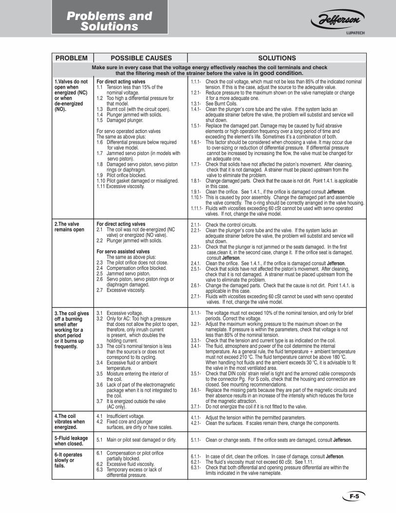
Problems andSolutions
PROBLEM
1.Valves do not open when energized (NC) or when de-energized (NO).
2.The valve remains open
3. The coil gives off a burning smell after working for a short period or it burns up frequently.
4.The coil vibrates when energized.
5-Fluid leakage when closed.
6- It operates slowly or fails.
For direct acting valves1.1 Tension less than 15% of the nominal voltage.1.2 Too high a differential pressure for that model.1.3 Burnt coil (with the circuit open).1.4 Plunger jammed with solids.1.5 Damaged plunger.
For servo operated action valvesThe same as above plus:1.6 Differential pressure below required for valve model.1.7 Jammed servo piston (in models with servo piston).1.8 Damaged servo piston, servo piston rings or diaphragm.1.9 Pilot orifi ce blocked.1.10 Pilot gasket damaged or misaligned.1.11 Excessive viscosity.
For direct acting valves2.1 The coil was not de-energized (NC valve) or energized (NO valve).2.2 Plunger jammed with solids.
For servo assisted valves The same as above plus:2.3 The pilot orifi ce does not close.2.4 Compensation orifi ce blocked.2.5 Jammed servo piston.2.6 Servo piston, servo piston rings or diaphragm damaged.2.7 Excessive viscosity.
3.1 Excessive voltage.3.2 Only for AC: Too high a pressure that does not allow the pilot to open, therefore, only inrush current is present, which doubles the holding current.3.3 The coil’s nominal tension is less than the source’s or does not correspond to its cycling.3.4 Excessive fl uid or ambient temperature.3.5 Moisture entering the interior of the coil.3.6 Lack of part of the electromagnetic package when it is not integrated to the coil.3.7 It is energized outside the valve (AC only).
4.1 Insuffi cient voltage.4.2 Fixed core and plunger surfaces, are dirty or have scales. 5.1 Main or pilot seat damaged or dirty.
6.1 Compensation or pilot orifi ce partially blocked.6.2 Excessive fl uid viscosity.6.3 Temporary excess or lack of differential pressure.
SOLUTIONSPOSSIBLE CAUSESMake sure in every case that the voltage energy effectively reaches the coil terminals and check
that the fi ltering mesh of the strainer before the valve is in good condition.1.1.1- Check the coil voltage, which must not be less than 85% of the indicated nominal tension. If this is the case, adjust the source to the adequate value.1.2.1- Reduce pressure to the maximum shown on the valve nameplate or change it for a more adequate one.1.3.1- See Burnt Coils.1.4.1- Clean the plunger’s core tube and the valve. If the system lacks an adequate strainer before the valve, the problem will substist and service will shut down.1.5.1- Replace the damaged part. Damage may be caused by fl uid abrasive elements or high operation frequency over a long period of time and exceeding the element’s life. Sometimes it’s a combination of both.1.6.1- This factor should be considered when choosing a valve. It may occur due to over-sizing or reduction of differential pressure. If differential pressure cannot be increased by increasing the fl ow, the valve must be changed for an adequate one.1.7.1- Check that solids have not affected the piston’s movement. After cleaning, check that it is not damaged. A strainer must be placed upstream from the valve to eliminate the problem.1.8.1- Change damaged parts. Check that the cause is not dirt. Point 1.4.1. is applicable in this case.1.9.1- Clean the orifi ce. See 1.4.1., if the orifi ce is damaged consult Jefferson.1.10.1- This is caused by poor assembly. Change the damaged part and assemble the valve correctly. The o-ring should be correctly arranged in the valve housing.1.11.1- Fluids with vicosities exceeding 60 cSt cannot be used with servo operated valves. If not, change the valve model.
2.1.1- Check the control circuits.2.2.1- Clean the plunger’s core tube and the valve. If the system lacks an adequate strainer before the valve, the problem will substist and service will shut down.2.3.1- Check that the plunger is not jammed or the seats damaged. In the fi rst case,clean it, in the second case, change it. If the orifi ce seat is damaged, consult Jefferson.2.4.1. Clean the orifi ce. See 1.4.1., if the orifi ce is damaged consult Jefferson.2.5.1- Check that solids have not affected the piston’s movement. After cleaning, check that it is not damaged. A strainer must be placed upstream from the valve to eliminate the problem.2.6.1- Change the damaged parts. Check that the cause is not dirt. Point 1.4.1. is applicable in this case.2.7.1- Fluids with vicosities exceeding 60 cSt cannot be used with servo operated valves. If not, change the valve model.
3.1.1- The voltage must not exceed 10% of the nominal tension, and only for brief periods. Correct the voltage.3.2.1- Adjust the maximum working pressure to the maximum shown on the nameplate. If pressure is within the parameters, check that voltage is not less than 85% of the nominal tension.3.3.1- Check that the tension and current type is as indicated on the coil.3.4.1- The fl uid, atmosphere and power of the coil determine the internal temperature. As a general rule, the fl uid temperature + ambient temperature must not exceed 210 °C. The fl uid temperature cannot be above 180 °C. When handling hot fl uids and the ambient exceeds 30 °C, it is advisable to fi t the valve in the most ventilated area.3.5.1- Check that DIN coils’ strain relief is tight and the armored cable corresponds to the connector Pg. For S coils, check that the housing and connection are closed. See mounting recommendations.3.6.1- Replace the missing parts because they are part of the magnetic circuits and their absence results in an increase of the intensity which reduces the force of the magnetic attraction.3.7.1- Do not energize the coil if it is not fi tted to the valve.
4.1.1- Adjust the tension within the permitted parameters.4.2.1- Clean the surfaces. If scales remain there, change the components.
5.1.1- Clean or change seats. If the orifi ce seats are damaged, consult Jefferson.
6.1.1- In case of dirt, clean the orifi ces. In case of damage, consult Jefferson.6.2.1- The fl uid’s viscosity must not exceed 60 cSt. See 1.11.6.3.1- Check that both differential and opening pressure differential are within the limits indicated in the valve nameplate.
F-5

RepairKits
F-6
1342BV20INA1342BV24INA
1390BA21390BA31390BA41390BE21390BE31390BE41390BN21390BN31390BN41390BT21390BT31390BT41390BV21390BV31390BV41390BA2INA1390BA3INA1390BA4INA1390BE2INA1390BE3INA1390BE4INA1390BN2INA1390BN3INA1390BN4INA1390BT2INA1390BT3INA1390BT4INA1390BV2INA1390BV3INA
1390BV4INA
K42V5INAK42V5INA
K90BA1
K90BA2
K90BE1
K90BE2
K90BN1
K90BN2
K90BT1
K90BT2
K90BV1
K90BV2
K90BA1INA
K90BA2INA
K90BE1INA
K90BE2INA
K90BN1INA
K90BN2INA
K90BT1INA
K90BT2INA
K90BV1INA
K90BV2INA
General Purpose
1327BT1221327BT1721327BT2221327BT3021327BT4021327BV1221327BV1721327BV2221327BV3021327BV4021327BV5021327BV5221327BA122NA1327BA172NA1327BA222NA1327BA252NA1327BA302INA1327BA402INA1327BA502INA1327BE122NA1327BE172NA1327BE222NA1327BE252NA1327BE302INA1327BE402INA1327BE502INA1327BN122NA1327BN172NA1327BN222NA1327BN252NA1327BN302INA1327BN402INA1327BN502INA1327BT122INA1327BT172INA1327BT222INA1327BT302INA1327BT402INA1327BV122NA1327BV172NA1327BV222NA1327BV252NA1327BV302INA1327BV402INA
1335BA3D1335BA4D1335BA6D1335BE3D1335BE4D1335BE6D1335BN3D1335BN4D1335BN6D1335BV3D1335BV4D1335BV6D1335BA31335BA41335BA61335BE31335BE4
1314BA061314BA081314BA121314BA161314BE061314BE081314BE121314BE161314BN061314BN081314BN121314BN161314BST061314BST081314BST121314BST161314BV061314BV081314BV121314BV161314BA06A1314BA08A1314BA12A1314BA16A1314BE06A1314BE08A1314BE12A1314BE16A1314BN06A1314BN08A1314BN12A1314BN16A1314BST06A1314BST08A1314BST12A1314BST16A1314BV06A1314BV08A1314BV12A1314BV16A
1327BA1221327BA1721327BA2221327BA3021327BA4021327BA5021327BA5221327BE1221327BE1721327BE2221327BE3021327BE4021327BE5021327BE5221327BN1221327BN1721327BN2221327BN3021327BN4021327BN5021327BN522
CatalogNº
Kitpart Nº
K14A1K14A2
K14A3
K14T1K14T2
K14T3
K14N1K14N2
K14N3
K14T1K14T2
K14T3
K14V1K14V2
K14V3
K14A1K14A2
K14A3
K14T1K14T2
K14T3
K14N1K14N2
K14N3
K14T1K14T2
K14T3
K14V1K14V2
K14V3
K27A
K27E
K27N
1314
CatalogNº
Kitpart Nº
K27T
K27V
K27AA
K27AINA
K27EA
K27EINA
K27NA
K27NINA
K27TINA
K27VA
K27VINA
K35A1D
K35A2D
K35E1D
K35E2D
K35N1D
K35N2D
K35V1D
K35V2D
K35A1
K35A2
K35E1
CatalogNº
1335BE61335BN31335BN41335BN61335BV31335BV41335BV61335BA3A1335BA4A1335BA6A1335BE3A1335BE4A1335BE6A1335BN3A1335BN4A1335BN6A1335BV3A1335BV4A1335BV6A1335BA3INA1335BA4INA1335BA6INA1335BE3INA1335BE4INA1335BE6INA1335BN3INA1335BN4INA1335BN6INA1335BV3INA1335BV4INA1335BV6INA
1342BA061342BA081342BA121342BA161342BA201342BA241342BE061342BE081342BE121342BE161342BE201342BE241342BN061342BN081342BN121342BN161342BN201342BN241342BT061342BT081342BT121342BT161342BT201342BT241342BV061342BV081342BV121342BV161342BV201342BV24
Kitpart Nº
K35E2
K35N1
K35N2
K35V1
K35V2
K35A1A
K35A2A
K35E1A
K35E2A
K35N1A
K35N2A
K35V1A
K35V2A
K35A1INA
K35A2INA
K35E1INA
K35E2INA
K35N1INA
K35N2INA
K35V1INA
K35V2INA
K42A1K42A2K42A3K42A4
K42A5
K42E1K42E2K42E3K42E4
K42E5
K42N1K42N2K42N3K42N4
K42N5
K42T1K42T2K42T3K42T4
K42T5
K42V1K42V2K42V3K42V4
K42V5
1327
CatalogNº
1342BA06INA1342BA08INA1342BA12INA1342BA16INA1342BA20INA1342BA24INA1342BE06INA1342BE08INA1342BE12INA1342BE16INA1342BE20INA1342BE24INA1342BN06INA1342BN08INA1342BN12INA1342BN16INA1342BN20INA1342BN24INA1342BT06INA1342BT08INA1342BT12INA1342BT16INA1342BT20INA1342BT24INA1342BV06INA1342BV08INA1342BV12INA1342BV16INA
Kitpart Nº
K42A1INAK42A2INAK42A3INAK42A4INA
K42A5INA
K42E1INAK42E2INAK42E3INAK42E4INA
K42E5INA
K42N1INAK42N2INAK42N3INAK42N4INA
K42N5INA
K42T1INAK42T2INAK42T3INAK42T4INAK42T5INAK42T5INAK42V1INAK42V2INAK42V3INAK42V4INA
1342
1327
1335
1335
13421390

RepairKits
F-7
1323BA17C1323BA20C1323BA25C1323BE17C1323BE20C1323BE25C1323BN17C1323BN20C1323BN25C1323BV17C1323BV20C1323BV25C1323BA17D1323BA20D1323BA25D1323BE17D1323BE20D1323BE25D1323BN17D1323BN20D1323BN25D1323BV17D1323BV20D
General Purpose Combustion Use
K12B1
K12B2
K12S1
K12S2
K12B1
K12B2
K12S1
K12S2
K30A0
K30A1
K030A1
K30A2
K030A2
K30A2L
K030A2L
K30AR2
K030AR2
K30A1A
K30A2
K030A2
K30AR2
K030AR2
K32A1K32A2
K32A3
K32A4
K56B1
K56B2
K88A2D
K88A3D
K88A5D
K88A6D
CatalogNº
Kitpart Nº
1312 - 20121312BS5041312BS5061312BS8061312BS8081312BSB081312SS5041312SS5061312SS8061312SS8081312SSB081312BS404NA1312BS406NA1312BS606NA1312BS408NA1312BS608NA1312SS404NA1312SS406NA1312SS606NA1312SS408NA1312SS608NA
1330LA01330LA041330LA062030LA082030LA101330LA082030LA122030LA161330LA08L2030LA12L2030LA16L1330LAR082030LAR122030LAR161330LA04NA1330LA06NA1330LA08NA2030LA12NA2030LA16NA1330LAR08NA2030LAR12NA2030LAR16NA
1332LA081332LA101332LA121332LA161332LA201332LA24
1356BT31356BT41356BS4-48
1388LA06D1388LA08D1388LA10D1388LA12D1388LA16D1388LA20D
1388LA24D
1356
1330 - 2030
1332
1388
CatalogNº
11388LA06DS1388LA08DS1388LA10DS1388LA12DS1388LA16DS1388LA20DS1388LA24DS1388LA06A1388LA08A
1388LA12A1388LA16A
1388LA20A
1388LA24A1388LA06AR1388LA08AR1388LA12AR1388LA16AR1388LA20AR1388LA24AR
RC 2088LA08DLRC 2088LA10DLRC 2088LA12DLRC 2088LA16DLRC 2088LA08DRRC 2088LA10DRRC 2088LA12DRRC 2088LA16DRRC 2088LA08LRC 2088LA10LRC 2088LA12LRC 2088LA16LRC 2088LA08RRC 2088LA10RRC 2088LA12RRC 2088LA16R
Kitpart Nº
K88A2D
K88A3D
K88A5D
K88A6D
K88A2A
K88A4A
K88A6A
K88A2A
K88A4A
K88A6A
K088D1L
K088D2LK088D3L
K088D1R
K088D2RK088D3R
K0881L
K0882LK0883L
K0881R
K0882RK0883R
1388
2088
Pneumatic Use1323
K23AC
K23EC
K23NC
K23VC
K23AD
K23ED
K23ND
K23VD
CatalogNº
Kitpart Nº
13931393BS082
K93T1
1393BS0831393BS0841393NS0821393NS0831393NS084
1393BS082NA1393BS083NA1393BS084NA1393NS082NA1393NS083NA1393NS084NA
20262026BA121
K026A
2026BA1712026BA2212026BA3012026BA1222026BA1722026BA2222026BA3022026BE121
K026E
2026BE1712026BE2212026BE3012026BE1222026BE1722026BE2222026BE3022026BN121 K026E2026BN171
K026N
2026BN2212026BN3012026BN1222026BN1722026BN2222026BN3022026BV121
K026V
2026BV1712026BV2212026BV3012026BV1222026BV1722026BV2222026BV302
20362036BA03/4 K036A012036BA06 K036A022036BA08 K036A032036BE03/4 K036E012036BE06 K036E022036BE08 K036E032036BN03/4 K036N012036BN06 K036N022036BN08 K036N032036BT03/4 K036T012036BT06 K036T022036BT08 K036T032036BV03/4 K036V012036BV06 K036V022036BV08 K036V03
13591359BS04 K59S11359BS06 K59S21359BS08 K59S31359BS12 K59S41359BS16 K59S51359FS04 K59S11359FS06 K59S21359FS08 K59S31359FS12 K59S41359FS16 K59S5
CatalogNº
Kitpart Nº
13231323BV25D K23VD1323BA17A
K23AA1323BA20A1323BA25A1323BE17A
K23EA1323BE20A1323BE25A1323BN17A
K23NA1323BN20A1323BN25A1323BV17A
K23VA1323BV20A1323BV25A1323BA17U
K23AU1323BA20U1323BA25U1323BE17U
K23EU1323BE20U1323BE25U1323BN17U
K23NU1323BN20U1323BN25U1323BV17U
K23VU1323BV20U1323BV25U
13251325BA3C
K25AC1325BA4C1325BA6C1325BV3C
K25VC1325BV4C1325BV6C1325BA3A
K25AA1325BA4A1325BA6A1325BV3A
K25VA1325BV4A1325BV6A1325SA3C
K25SA1C1325SA4C1325SA6C K25SA2C1325SV3C
K25SV1C1325SV4C1325SV6C K25SV2C1325SA3A
K25SA1A1325SA4A1325SA6A K25SA2A1325SV3A
K25SV1A1325SV4A1325SV6A K25SV2A
13391339LA1
K39A1339LA21339LA31339LV1
K39AV1339LV21339LV31339BA1
K39B1339BA21339BA31339BV1
K39BV1339BV21339BV31339SA1
K39A1339SA21339SA31339SV1
K39AV1339SV21339SV3
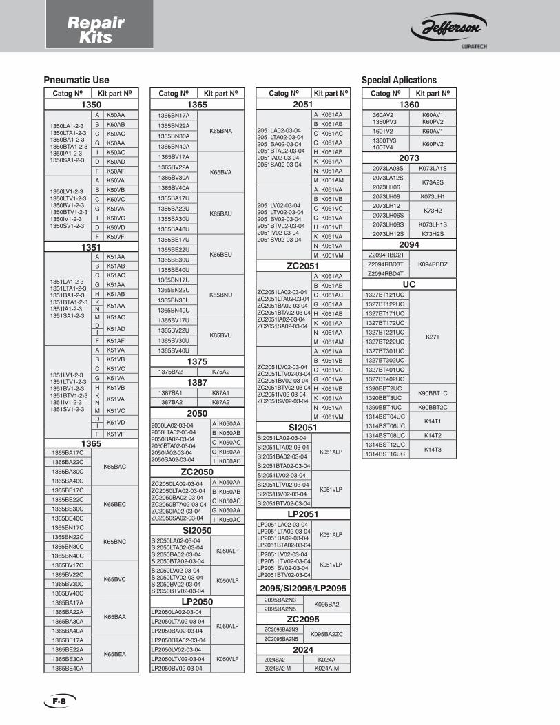
RepairKits
F-8
Pneumatic UseCatog Nº Kit part Nº
1350
1350LA1-2-31350LTA1-2-31350BA1-2-31350BTA1-2-31350IA1-2-31350SA1-2-3
A K50AAB K50ABC K50ACG K50AAI K50ACD K50ADF K50AF
1350LV1-2-31350LTV1-2-31350BV1-2-31350BTV1-2-31350IV1-2-31350SV1-2-3
A K50VAB K50VBC K50VCG K50VAI K50VCD K50VDF K50VF
1351
1351LA1-2-31351LTA1-2-31351BA1-2-31351BTA1-2-31351IA1-2-31351SA1-2-3
A K51AAB K51ABC K51ACG K51AAH K51ABK K51AANM K51ACD K51ADIF K51AF
1351LV1-2-31351LTV1-2-31351BV1-2-31351BTV1-2-31351IV1-2-31351SV1-2-3
A K51VAB K51VBC K51VCG K51VAH K51VBK K51VANM K51VCD K51VDIF K51VF
13651365BA17C
K65BAC1365BA22C1365BA30C1365BA40C1365BE17C
K65BEC1365BE22C1365BE30C1365BE40C1365BN17C
K65BNC1365BN22C1365BN30C1365BN40C1365BV17C
K65BVC1365BV22C1365BV30C1365BV40C1365BA17A
K65BAA1365BA22A1365BA30A1365BA40A1365BE17A
K65BEA1365BE22A1365BE30A1365BE40A
Catog Nº Kit part Nº1365
1365BN17A
K65BNA1365BN22A
1365BN30A
1365BN40A
1365BV17A
K65BVA1365BV22A
1365BV30A
1365BV40A
1365BA17U
K65BAU1365BA22U
1365BA30U
1365BA40U
1365BE17U
K65BEU1365BE22U
1365BE30U
1365BE40U
1365BN17U
K65BNU1365BN22U
1365BN30U
1365BN40U
1365BV17U
K65BVU1365BV22U
1365BV30U
1365BV40U
13751375BA2 K75A2
13871387BA1 K87A11387BA2 K87A2
Catog Nº Kit part Nº1360
360AV21360PV3
K60AV1K60PV2
160TV2 K60AV11360TV3160TV4 K60PV2
20732073LA08S K073LA1S2073LA12S
K73A2S2073LH062073LH08 K073LH12073LH12
K73H22073LH06S2073LH08S K073LH1S2073LH12S K73H2S
2094 Z2094RBD2T
K094RBDZZ2094RBD3TZ2094RBD4T
UC1327BT121UC
K27T
1327BT122UC1327BT171UC1327BT172UC1327BT221UC1327BT222UC1327BT301UC1327BT302UC1327BT401UC1327BT402UC1390BBT2UC
K90BBT1C1390BBT3UC1390BBT4UC K90BBT2C1314BST04UC
K14T11314BST06UC1314BST08UC K14T21314BST12UC
K14T31314BST16UC
Special AplicationsCatog Nº Kit part Nº
2051
2051LA02-03-042051LTA02-03-042051BA02-03-042051BTA02-03-042051IA02-03-042051SA02-03-04
A K051AAB K051ABC K051ACG K051AAH K051ABK K051AAN K051AAM K051AM
2051LV02-03-042051LTV02-03-042051BV02-03-042051BTV02-03-042051IV02-03-042051SV02-03-04
A K051VAB K051VBC K051VCG K051VAH K051VBK K051VAN K051VAM K051VM
ZC2051
ZC2051LA02-03-04ZC2051LTA02-03-04ZC2051BA02-03-04ZC2051BTA02-03-04ZC2051IA02-03-04ZC2051SA02-03-04
A K051AAB K051ABC K051ACG K051AAH K051ABK K051AAN K051AAM K051AM
ZC2051LV02-03-04ZC2051LTV02-03-04ZC2051BV02-03-04ZC2051BTV02-03-04ZC2051IV02-03-04ZC2051SV02-03-04
A K051VAB K051VBC K051VCG K051VAH K051VBK K051VAN K051VAM K051VM2050
2050LA02-03-042050LTA02-03-042050BA02-03-042050BTA02-03-042050IA02-03-042050SA02-03-04
A K050AAB K050ABC K050ACG K050AAI K050AC
ZC2050ZC2050LA02-03-04ZC2050LTA02-03-04ZC2050BA02-03-04ZC2050BTA02-03-04ZC2050IA02-03-04ZC2050SA02-03-04
A K050AAB K050ABC K050ACG K050AAI K050AC
SI2050SI2050LA02-03-04SI2050LTA02-03-04SI2050BA02-03-04SI2050BTA02-03-04
K050ALP
SI2050LV02-03-04SI2050LTV02-03-04SI2050BV02-03-04SI2050BTV02-03-04
K050VLP
LP2050LP2050LA02-03-04
K050ALPLP2050LTA02-03-04LP2050BA02-03-04LP2050BTA02-03-04LP2050LV02-03-04
K050VLPLP2050LTV02-03-04LP2050BV02-03-04
2095/SI2095/LP20952095BA2N3
K095BA22095BA2N5
ZC2095ZC2095BA2N3
K095BA2ZCZC2095BA2N5
20242024BA2 K024A2024BA2-M K024A-M
SI2051SI2051LA02-03-04
K051ALPSI2051LTA02-03-04SI2051BA02-03-04SI2051BTA02-03-04SI2051LV02-03-04
K051VLPSI2051LTV02-03-04SI2051BV02-03-04SI2051BTV02-03-04
LP2051LP2051LA02-03-04LP2051LTA02-03-04LP2051BA02-03-04LP2051BTA02-03-04
K051ALP
LP2051LV02-03-04LP2051LTV02-03-04LP2051BV02-03-04LP2051BTV02-03-04
K051VLP

Equivalences
Weight
Power
Pressure
1
0.453
2.207
1
kg.
Pounds
Temperature
Volume
Density
ConversionTable
Note: Column units: Origin Units.Line units: Resultant Units.In order to obtain the results, intersection coeffi cients must be multiplied by the known value of the origin unit. For temperature conversion use given formulas.
Poundskg.
Kinematic Viscosity (approximate)
Jefferson shall notbe held responsible for any mistakes in this catalog. The company reserves the right to modify product characteristics provided that they do not after what has been agreed upon with the client. This catalog was prepared by
Jefferson’s Technical-Commercial Department. Printed in February 2013.
1
0.093
10-6
2.2 x 10⁻⁷
7.5 x 10⁻⁶
7.5 x 10⁶
7 x 10⁵
0.133
0.029
1
4.6 x 10⁶
4.28 x 10⁵
4.6
1
34.5
m2/s
ft2/s
cSt.
SSU
°E
10.76
1
10.76 x 10⁻⁶
22.8 x 10⁻⁶
1.43 x 10⁻⁶
106
93000
1
0.217
7.5
m2/s °EcStft2/s SSU
1
°C x 1.8 +32
°K x 1.8 - 459.69
°K - 459.69
(°F - 32) / 1.8
1
°K - 273.16
(°R - 491.69) / 1.8
(°F + 459.69) / 1.8
°C + 273.16
1
°R / 1.8
°F
°C
°K
°R
°F + 459.69
°C x 1.8 + 491.69
°K x 1.8
1
°F °K °R°C1
16.018
Kg./m3
Lb./Ft3
0.0624
1
Lb./ft3Kg./m3
1
0.00116
0.000293
3.5168
0.284
0.0003306
0.0000833
1
Kw
Kcal./H
BTU/H
Refrig.Ton.
860
1
0.252
3024
3412
3.968
1
12000
Kw. BTU/HKcal./H Refrig. Ton.
1
1000
3.785
28.32
0.0353
35.31
7.481
1
Liters
m3
Gall.USA
Ft3
0.001
1
0.00378
0.02832
0.264
264
1
0.1337
Liters Gall.USAm3 ft3
1
0.0102
1.02
0.0703
0.00136
0.0345
736
0.75
750
51.76
1
0.0394
28.97
0.295
29.53
2.036
25.4
1
14.22
0.145
14.5
1
0.0193
0.491
Kg./cm2
KPa.
bar.
Psi.
mm.c.hg.
Inch.c.hg.
98.1
1
100
6.897
0.133
3.39
0.981
0.01
1
0.069
0.00133
0.0339
Kg./cm2 mm.c.hg.bar.KPa. Psi. Inch.c.hg.
H-1
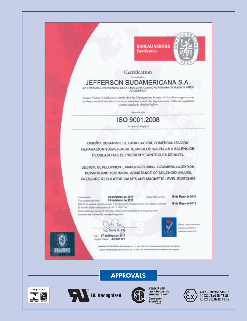
APPROVALS
UL RecognizedATEX - Directive 94/9
II2G / Ex d IIB T3 Gb II2D / Ex tb IIIC T3 Db
N C COCP 0034
Segurança Associationcanadienne de normalisationCanadianStandars Association
DISTRIBUITOR:
JEFFERSONSOLENOID VALVES U.S.A. INCENGINEERING FOR INDUSTRIAL AUTOMATIONSolenoid Valves and Level Switches
20225 NE 15TH CTMiami, FL 33179 - USATel: 305-249-8120 / Fax: 305-249-8121Toll Free: 1-866-42-VALVE (82583)[email protected]
Top Related