


Languages
Pages
Legal


Available online at www.sciencedirect.com
Physica E 22 (2004) 164–167www.elsevier.com/locate/physe
Probing the electrostatics of integer quantum hall edges withmomentum-resolved tunnel spectroscopy
M. Hubera ;∗, M. Graysona ;1, D. Schuha, M. Bichlera, W. Biberacherb, W. Wegscheiderc,G. Abstreitera
aWalter Schottky Institut, Technical University, Munich Am Coulombwall, 85748 Garching, GermanybWalther-Meissner-Institut, Walther-Meissner-Strasse 8, 85748 Garching, Germany
cUniversit#at Regensburg, Universit#atsstrasse 1, 93040 Regensburg, Germany
Abstract
We present measurements of momentum-resolved magneto-tunneling from a perpendicular two-dimensional (2D) contactinto integer quantum Hall (QH) edges at a sharp-edge potential created by cleaved-edge overgrowth. Resonances in thetunnel conductance correspond to coincidences of electronic states of the QH edge and the 2D contact in energy–momentumspace. With this dispersion relation re0ecting the potential distribution at the edge we can directly measure the band bendingat our cleaved edge under the in0uence of an external voltage bias. At 2nite bias we observe signi2cant deviations from the0at-band condition in agreement with self-consistent calculations of the edge potential.? 2003 Elsevier B.V. All rights reserved.
PACS: 73.43.Jn; 71.70.Di
Keywords: Quantum Hall e7ect; Edge; Tunneling; Momentum-resolved
1. Introduction
The quantum Hall (QH) e7ect arises due to energygaps developing in the spectrum of two-dimensional(2D) electron systems with a perpendicular magnetic2eld. At speci2c ratios of electron sheet density andmagnetic 2eld, when the Fermi-energy is in such a gap,the only low-energy excitations in a 2nite QH sampleare located at the boundary, where the energeticallybent Landau-levels intersect the Fermi-energy. These
∗ Corresponding author Tel.: +49-89-289-12756;fax: +49-89-320-6620.
E-mail addresses: [email protected](M. Huber), [email protected] (M. Grayson).
1 Also corresponding author.
states at the sample edge exhibit one-dimensional (1D)chiral transport behavior, i.e. quantized conductance,independent of the exact electrostatics at the sam-ple boundary, so standard transport measurements donot provide information about such physics as deple-tion lengths, edge reconstructions, or edge excitations.The technique of edge tunneling in cleaved-edge over-growth (CEO) devices was introduced to address thelast question of edge excitations in particular. 2D–3Dtunneling at a sharp edge was used to observe thepower-law density of states of fractional QH edges[1–5] and discrepancies among experiments suggestedthat the exact potential shape at the edge might be cru-cial for de2ning the correlations at the QH edge. Byreplacing the 3D disordered contact with a high mobil-ity 2D system, one can perform momentum-resolved
1386-9477/$ - see front matter ? 2003 Elsevier B.V. All rights reserved.doi:10.1016/j.physe.2003.11.241
M. Huber et al. / Physica E 22 (2004) 164–167 165
tunnel spectroscopy of the QH edge. The 2rst suchexperiment was performed by Kang et al. [6] betweentwo coplanar QH edges. However, the e7ect of screen-ing in the 2D edge was not addressed so a quantitativeanalysis of the resonance positions was lacking.
In this paper we present a new momentum-resolvedtunnel geometry where the tunnel contact is an or-thogonal high mobility 2D system [7]. This allowsmomentum-resolved tunnel spectroscopy of the QHedge. In the fractional QH regime this geometry ispredicted to probe the spectral function of chargedand neutral modes at speci2c 2lling factors [8]. In thispaper we study the edge dispersion of Landau levelsin the integer QH regime and address for the 2rsttime the e7ect of edge electrostatics on the observedresonance positions.
2. Sample design
The samples consist of two separately contactedperpendicular high mobility quantum wells (QW)(QW⊥ and QW‖) forming a T-shaped structure(Fig. 1), where ⊥ and ‖ are de2ned relative to thequantizing B 2eld. These QWs consist of GaAs em-bedded in Al0:32Ga0:78As. Using CEO, a 150 LA thick(0 0 1)-QW (QW⊥) is cleaved along the perpendic-ular (1 1 0)-plane and overgrown with a w = 200 LAthick (1 1 0)-QW (QW‖) in a second epitaxial growthstep. The QW are separated from each other by ab = 50 LA thick �B = 320 meV high Al0:32Ga0:78Astunnel barrier. Both QWs are modulation doped witha Si-� layer 500 and 400 LA away from the respective
AlG
aAs
(110)
x
z
y
(001)δ-doping
edgechannels
B
AlGaAs tunneljunctionQW QW
QW
||
X
⊥
Fig. 1. The samples are fabricated by cleaved edge overgrowth.Two quantum wells (QW⊥ and QW‖) are arranged in a T-shape.A magnetic 2eld B creates QH edge states close to the tunnelbarrier.
V (mV) V (mV)
dI/d
V (
µS)
-80 -80-60 -60-40 -40-20 -200 020
1 T increments
4T
2T0
10
20
30
40
50
0
2
4
6
8
10
B (T
)
experiment
without screening
with screening
400 mK
6T
10T
8T
10T
(a) (b)
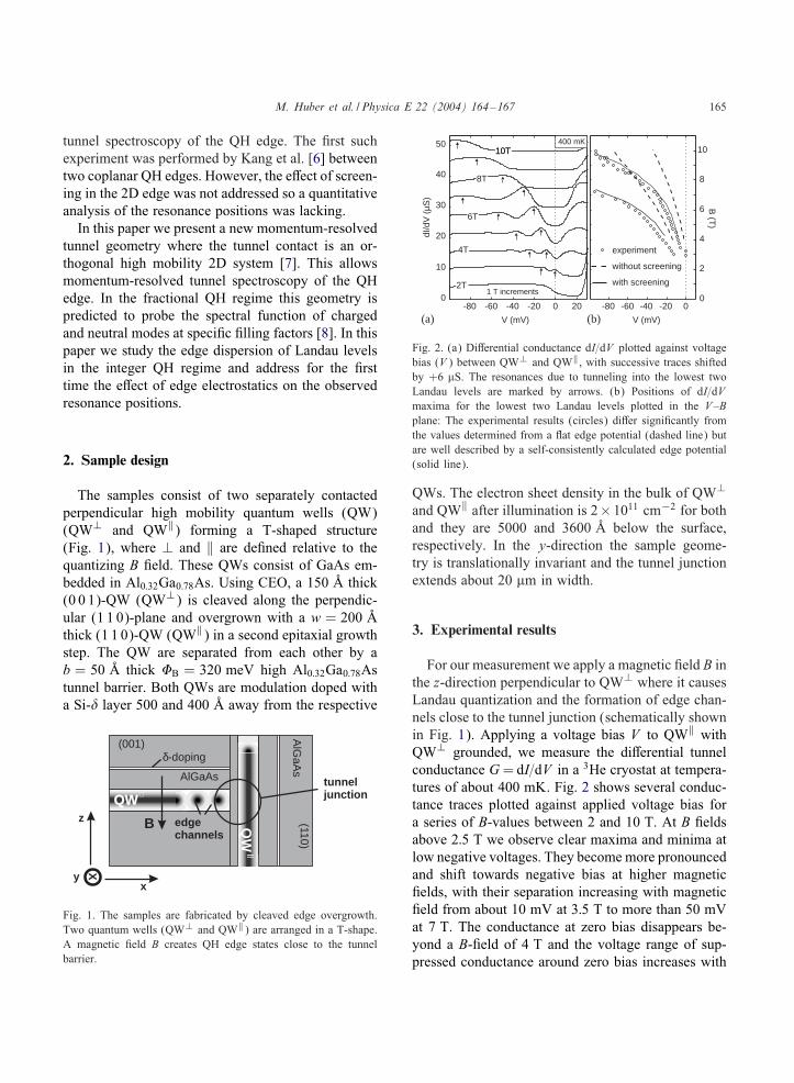
Fig. 2. (a) Di7erential conductance dI=dV plotted against voltagebias (V ) between QW⊥ and QW‖, with successive traces shiftedby +6 �S. The resonances due to tunneling into the lowest twoLandau levels are marked by arrows. (b) Positions of dI=dVmaxima for the lowest two Landau levels plotted in the V–Bplane: The experimental results (circles) di7er signi2cantly fromthe values determined from a 0at edge potential (dashed line) butare well described by a self-consistently calculated edge potential(solid line).
QWs. The electron sheet density in the bulk of QW⊥
and QW‖ after illumination is 2×1011 cm−2 for bothand they are 5000 and 3600 LA below the surface,respectively. In the y-direction the sample geome-try is translationally invariant and the tunnel junctionextends about 20 �m in width.
3. Experimental results
For our measurement we apply a magnetic 2eld B inthe z-direction perpendicular to QW⊥ where it causesLandau quantization and the formation of edge chan-nels close to the tunnel junction (schematically shownin Fig. 1). Applying a voltage bias V to QW‖ withQW⊥ grounded, we measure the di7erential tunnelconductance G = dI=dV in a 3He cryostat at tempera-tures of about 400 mK. Fig. 2 shows several conduc-tance traces plotted against applied voltage bias fora series of B-values between 2 and 10 T. At B 2eldsabove 2:5 T we observe clear maxima and minima atlow negative voltages. They become more pronouncedand shift towards negative bias at higher magnetic2elds, with their separation increasing with magnetic2eld from about 10 mV at 3:5 T to more than 50 mVat 7 T. The conductance at zero bias disappears be-yond a B-2eld of 4 T and the voltage range of sup-pressed conductance around zero bias increases with

166 M. Huber et al. / Physica E 22 (2004) 164–167
higher B-2elds. At 10 T the conductance is suppresseddown to almost −60 mV.
4. Discussion
In the presence of a magnetic 2eld the electronicstates in QW⊥ are quantized to Landau levels withenergy gaps proportional to B. With an applied junc-tion bias V the con2ning edge potential �(x; V ) entersinto the full Schroedinger equation as[
(p− eA)2
2m∗ + �(x; V )]�(x; y) = E�(x; y): (1)
With a Landau gauge A(x; y) = xBy where x = 0 inthe center of QW‖, Eq. (1) becomes translationallyinvariant in the y-direction. Expressing �n(x; y) = n(x)eikyy, we can solve for the motion in x as well asthe dispersion E⊥
n (ky):[p2
x
2m∗ +12!2
cm∗(x − Ox)2 + �(x; V )
] n(x)
=E⊥n (ky) n(x); (2)
where Ox = kyl2B is the electron orbit guiding center, nis the Landau index, and lB =
√˝=eB de2nes the mag-
netic length. Fig. 3 shows the calculated E⊥n (ky) as-
suming a simple step function edge potential�(x; V )=�B�(x + w=2 + b) with no V dependent screening.
Alternatively, the k-space dispersion E‖(ky) ofQW‖ exhibits a parabolic shape with a well de2nedFermi point FP‖. From our choice of Landau gauge,the mass parabola will always be centered at ky = 0,as shown in Fig. 3. Since Zeemann splitting in GaAsis small and orbital e7ects from the in-plane 2eld canbe shown to be negligible 2 we neglect the in0uenceof the magnetic 2eld on QW‖.
The translational invariance of the geometry iny-direction together with the high mobility of the2DEGs and the high uniformity of the tunnel barriercauses both momentum ky and energy E to be con-served during tunneling. Graphically, this means thattunneling is only allowed where the dispersion curvesintersect in an E vs. ky plot, so resonances in the tunnelconductance correspond to the coincidence of one of
2 Calculations showed that the k-space position for FP‖ and thedispersion velocity there change less than 5% even up to 10 Twhere lB ¡W , so the parabolic dispersion assumption is justi2ed.
-eV
FP ||
FE ||
-5 -4 -3 -2 -1 0 1 2
2DEGQHE
heBm*
ky (108m-1)
E (
meV
)
0
10
20
30
-10 ∆k =eB x
hy
EF
FP
Fig. 3. Calculated dispersion relations E(ky) for the quantum Hallsystem in QW⊥ (QHE) and the 2DEG in QW‖ according toEq. (2) and shown with a 2nite bias V between the two systemsassuming a step-function edge potential with no screening. TheLorentz force proportional to B shifts the dispersion in k-space andthe bias V shifts the energy. The 2gure shows 2nite negative biasat B = 5:5 T, where the Fermi point FP‖ matches the dispersioncurve of the lowest Landau level at the QH edge resulting in aconductance peak.
the quasi-Fermi-points (FP⊥;FP‖) with such a cross-ing point (see Fig. 3). Applying a voltage bias shiftsthe dispersion curves in energy, and the magnetic2eld shifts them in momentum space with respect toeach other through the Lorentz impulse acquired bytunneling the e7ective distance Ox through the barrier:Rky = eB Ox=˝. Scanning both the voltage bias and themagnetic 2eld we can thus map out the entire E⊥ vs.ky space using FP‖ as a probe for the Landau-leveldispersion E⊥
n (ky). Magnetic 2elds above 4 T separatethe occupied states of both systems in the ky space,explaining why tunneling at zero bias is no longerpossible. Spin splitting is not resolved in thesemeasurements.
The experimental conductance maxima for the low-est two Landau levels are indicated by little arrowsin Fig. 2a and their positions are plotted in the V–Bplane (Fig. 2b, circles) for comparison with modelcalculations. It can be seen that the step-function po-tential model (dashed line) qualitatively explains theresonance features, though the predicted position is tothe right of what is experimentally measured. We canexplain this shift with a model that includes screeningat the 2D edge.
We perform a self-consistent Schroedinger–Poissoncalculation of the edge potential at a biased tunnel

M. Huber et al. / Physica E 22 (2004) 164–167 167
-1000 -750 -500 -250 0-10
0
10
20
30
40
x (Å)
(m
eV)
-80
-40
-60
-100
-20
0
V
QW QW ||
E F
+-
⊥
⊥
Fig. 4. Self-consistently calculated potential �(x; V ) at the edgeof QW⊥ for a series of applied bias voltages V (denoted inmV) at B = 0. The plotted lines represent the local bottom of the2D-subband in QW⊥. Electronic states are 2lled up to the Fermilevel E⊥
F . Note the onset of a depletion region at 10 mV bias.
junction without magnetic 2eld and plotted the resultin Fig. 4. There we have plotted �(x; V ) as the low-est 2D subband in QW⊥ as a function of position x.The subband is occupied up to the Fermi energy des-ignated by the dashed line. Even at zero bias the po-tential close to the edge is not 0at. Negative bias liftsthe subband energy above the Fermi level resultingin edge depletion of order 750 LA at −100 mV, forexample.
Based on the results of the zero B-2eld simulationfor �(x; V ) we now solve the Schroedinger equation(2) with B 2eld and calculated the position of the ex-pected maxima in the tunnel conductance (solid line,Fig. 2b). We observe the self-consistently calculatededge potential shows excellent agreement with the ex-periment.
We checked our self-consistent Schroedinger–Poisson calculations against the analytical model ofLevitov et al. [9] which was designed to model asimilar device geometry. We 2nd agreement with thezero bias density distribution to within 5% at lengthscales of 400 LA or more away from the barrier, but atshorter distances and large biases the analytical modelappears to underestimate the edge depletion undernegative bias as well as the edge accumulation underpositive bias. This is presumably a consequence ofthe 2nite screening length in QW⊥, in contrast with
the metallic charge mirror assumed in the analyticalmodel.
5. Conclusion
With the presented measurement we are able to di-rectly probe the dispersion relation E⊥
n (k) of QH edgestates. In this paper we focused on the regime at highmagnetic 2elds and moderate negative bias where onlythe lowest Landau level is occupied and the probedstates are empty. We observe a shift in the locationof the conductance maxima that directly reveals theband bending under bias at the tunnel junction, andis in excellent agreement with a self-consistent modelcalculation.
Acknowledgements
We gratefully thank U. ZTulicke and M. Gellerfor helpful discussions. This work was supported byDeutsche Forschungsgemeinschaft via Schwerpunkt-programm “Quanten-Hall-Systeme”.
References
[1] L.N. Pfei7er, K.W. West, H.L. Stormer, J.P. Eisenstein,K.W. Baldwin, D. Gershoni, J. Spectrosc. Appl. Phys. Lett. 56(1990) 1697.
[2] A.M. Chang, L.N. Pfei7er, K.W. West, Phys. Rev. Lett. 77(1996) 2538.
[3] M. Grayson, D.C. Tsui, L.N. Pfei7er, K.W. West, A.M. Chang,Phys. Rev. Lett. 80 (1998) 1062;M. Grayson, D.C. Tsui, L.N. Pfei7er, K.W. West, A.M. Chang,Phys. Rev. Lett. 86 (2001) 2645.
[4] A.M. Chang, M.K. Wu, C.C. Chi, L.N. Pfei7er, K.W. West,Phys. Rev. Lett. 86 (2001) 143.
[5] M. Hilke, D.C. Tsui, M. Grayson, L.N. Pfei7er, K.W. West,Phys. Rev. Lett. 87 (2001) 186806.
[6] W. Kang, H.L. Stormer, L.N. Pfei7er, K.W. Baldwin,K.W. West, Nature 403 (2000) 59.
[7] M. Huber, M. Grayson, M. Rother, R.A. Deutschmann,W. Biberacher, W. Wegscheider, M. Bichler, G. Abstreiter,Physica E 12 (2002) 125.
[8] U. ZTulicke, E. Shimshoni, M. Governale, Phys. Rev. B 65(2002) 241315.
[9] L.S. Levitov, A.V. Shytov, B.I. Halperin, Phys. Rev. B 64(2001) 075322.
Top Related