


Languages
Pages
Legal

PPC Porcelain Solid Core Post Insulators and Operating Rods IEC
ELECTRIFYING THE WORLD
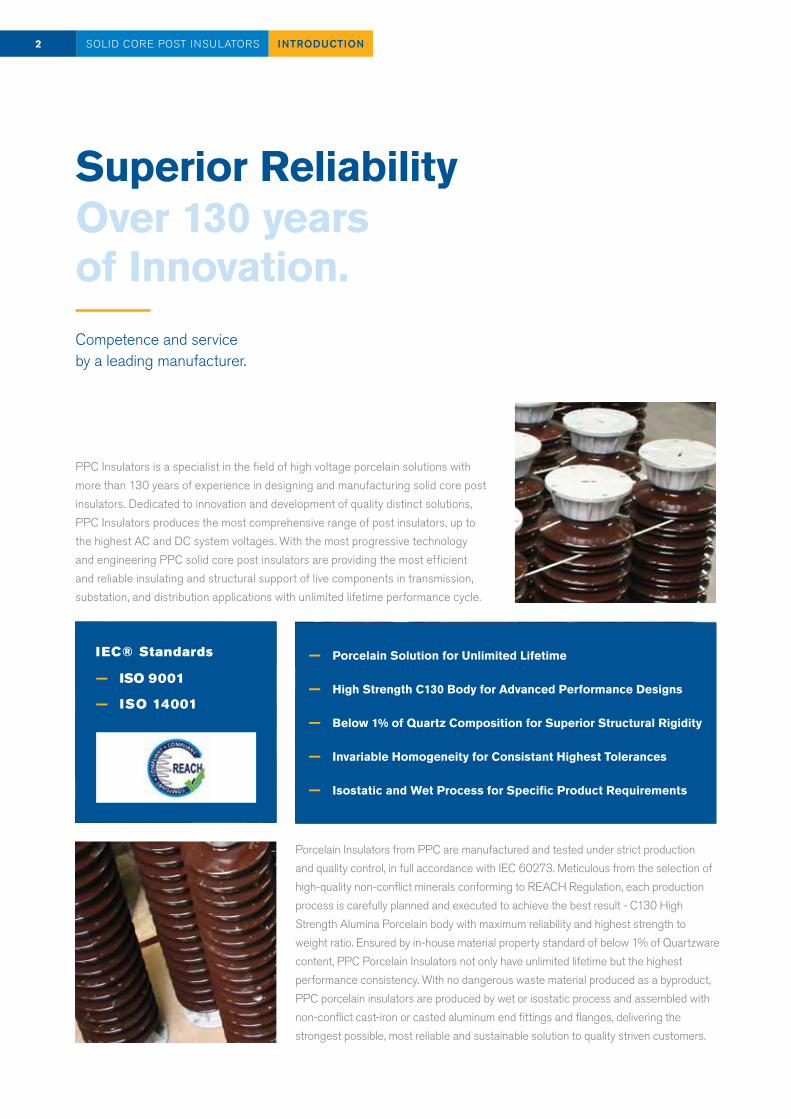
Superior Reliability Over 130 yearsof Innovation.
PPC Insulators is a specialist in the field of high voltage porcelain solutions with more than 130 years of experience in designing and manufacturing solid core post insulators. Dedicated to innovation and development of quality distinct solutions, PPC Insulators produces the most comprehensive range of post insulators, up to the highest AC and DC system voltages. With the most progressive technology and engineering PPC solid core post insulators are providing the most efficient and reliable insulating and structural support of live components in transmission, substation, and distribution applications with unlimited lifetime performance cycle.
Porcelain Insulators from PPC are manufactured and tested under strict production and quality control, in full accordance with IEC 60273. Meticulous from the selection of high-quality non-conflict minerals conforming to REACH Regulation, each production process is carefully planned and executed to achieve the best result - C130 High Strength Alumina Porcelain body with maximum reliability and highest strength to weight ratio. Ensured by in-house material property standard of below 1% of Quartzware content, PPC Porcelain Insulators not only have unlimited lifetime but the highest performance consistency. With no dangerous waste material produced as a byproduct, PPC porcelain insulators are produced by wet or isostatic process and assembled with non-conflict cast-iron or casted aluminum end fittings and flanges, delivering the strongest possible, most reliable and sustainable solution to quality striven customers.
2 INTRODUCTIONSOLID CORE POST INSULATORS
Competence and service by a leading manufacturer.
— Porcelain Solution for Unlimited Lifetime
— High Strength C130 Body for Advanced Performance Designs
— Below 1% of Quartz Composition for Superior Structural Rigidity
— Invariable Homogeneity for Consistant Highest Tolerances
— Isostatic and Wet Process for Specific Product Requirements
IEC® Standards
— ISO 9001
— ISO 14001
Title
INTRODUCTION
INDEX
PPC STRENGTHS
DESIGN
Pollution Levels
Shed Design
Insulating Material
Production
Testing
Key Features
RTV Coating
BIL 60-95 kV
BIL 125-170 kV
BIL 200-325 kV
BIL 450-650 kV
BIL 750-950 kV
BIL 1050-1300 kV
BIL 1425-1675 kV
BIL 1800-2100 kV
BIL 2250-2550 kV
Bina Test Station
Page
2
3
4
6
8
10
12
14
15
16
18
20
22
24
26
28
30
32
34
36
38
3INDEX SOLID CORE POST INSULATORS
Index
PPC Insulators The Edge Advantages.PPC’s experience, developed technology and persistent quality assures its customers
4 PPC STRENGTHSSOLID CORE POST INSULATORS
State-of-the-art technology
Comprehensive assistance and technical support
Over 130 years of experience
Fast response time
Contemporary products
Worldwide presence
5PPC STRENGTHS SOLID CORE POST INSULATORS
— Contemporary insulation solutions, i.e. Hybrid Post insulators and RTV-Coating, show ex-cellent performance in adverse environmental conditions, have improved pollution resis-tance and high durability due to mechanical strength of porcelain core.
— UHV and HVDC experience: Successfully delivered post insulators up to 1200kV
— In addition to the traditional production technology PPC also has Isostatic production technology that give more design flexibility including the possibility to produce shed profiles and creepage distances exceeding minimum IEC requirements
— Advanced porcelain post design with less metal parts and longer arcing distances increase substations performance
— Proximity to each market with a worldwide footprint including sites in Eu-rope, Asia and Latin America guarantees the availability of PPC’s products 24/7
— A comprehensive local customer service guaranteed by our global sales organization and supported by highly qualified local PPC representatives that provide competent per-sonal service to every single customer
— Quick responses to our customers’ delivery requirements by combining modern tools for design and leveraging our multiple manufac-turing sites and warehouses
— Tailored solutions serving customer specific design requirements by PPC’s international engineering team
— Superior technology and craftsmanship, supported by leading R&D for continuous product innovation
— Strict raw-material analysis and control
— High quality material for residual quartz content below 1%, preventing micro cracks in the porcelain, which grow under stresses and can seriously affect lifetime of insulators
— Compliance with all globally requested quality standards and exceed international standards and norms to provide ample safety margins for its customers
— ISO 9001 certification for all PPC plants.
— Close to zero replacement rates on site
Cus
tom
er
Inno
vatio
nQ
ualit
yE
xcel
lenc
eE
xcel
lenc
eE
xcel
lenc
e
Outdoor porcelain solid core post
insulator is determined according the
following characteristics:
— Lightning impulse withstand
voltage, dry
— Switching impulse withstand
voltage, wet (when a switching
impulse level is required)
— Power frequency withstand
voltage, wet
— Mechanical failing load
— Minimum nominal creepage
distance
— Fixing arrangement of top and
bottom metal fitting
— Color of glaze
6 DESIGNSOLID CORE POST INSULATORS
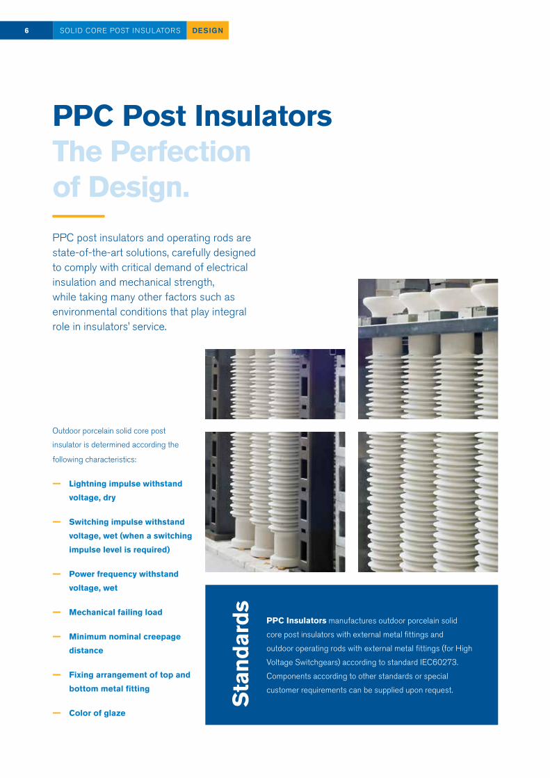
PPC post insulators and operating rods are state-of-the-art solutions, carefully designed to comply with critical demand of electrical insulation and mechanical strength, while taking many other factors such as environmental conditions that play integral role in insulators’ service.
PPC Insulators manufactures outdoor porcelain solid
core post insulators with external metal fittings and
outdoor operating rods with external metal fittings (for High
Voltage Switchgears) according to standard IEC60273.
Components according to other standards or special
customer requirements can be supplied upon request.
PPC Post Insulators The Perfection of Design.
Sta
ndar
ds
Ele
ctric
al
Des
ign
7DESIGN SOLID CORE POST INSULATORS
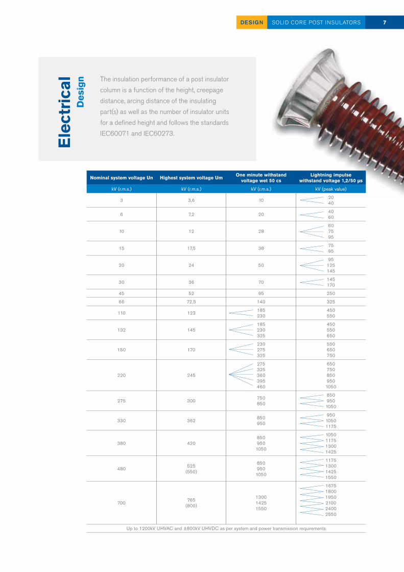
The insulation performance of a post insulator column is a function of the height, creepage distance, arcing distance of the insulating part(s) as well as the number of insulator units for a defined height and follows the standards IEC60071 and IEC60273.
Nominal system voltage Un Highest system voltage Um One minute withstand voltage wet 50 cs
Lightning impulse withstand voltage 1,2/50 µs
kV (r.m.s.) kV (r.m.s.) kV (r.m.s.) kV (peak value)
3 3,6 10 2040
6 7,2 20 4060
10 12 286075 95
15 17,5 38 7595
20 24 5095
125145
30 36 70 145170
45 52 95 250
66 72,5 140 325
110 123 185230
450550
132 145185230325
450550650
150 170230275325
550650750
220 245
275325360395460
650 7508509501050
275 300 750850
8509501050
330 362 850950
95010501175
380 4208509501050
1050117513001425
480 525 (550)
8509501050
1175130014251550
700 765(800)
130014251550
167518001950210024002550
Up to 1200kV UHVAC and ±800kV UHVDC as per system and power transmission requirements
8 DESIGNSOLID CORE POST INSULATORS
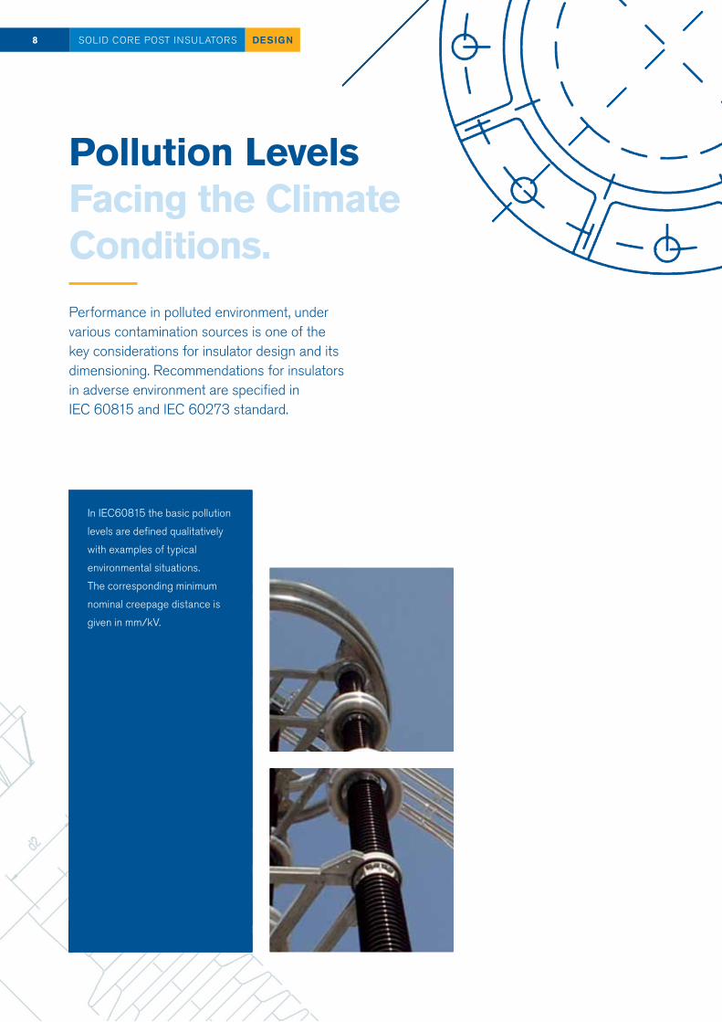
Pollution Levels Facing the Climate Conditions.Performance in polluted environment, undervarious contamination sources is one of the key considerations for insulator design and its dimensioning. Recommendations for insulators in adverse environment are specified in IEC 60815 and IEC 60273 standard.
In IEC60815 the basic pollution
levels are defined qualitatively
with examples of typical
environmental situations.
The corresponding minimum
nominal creepage distance is
given in mm/kV.
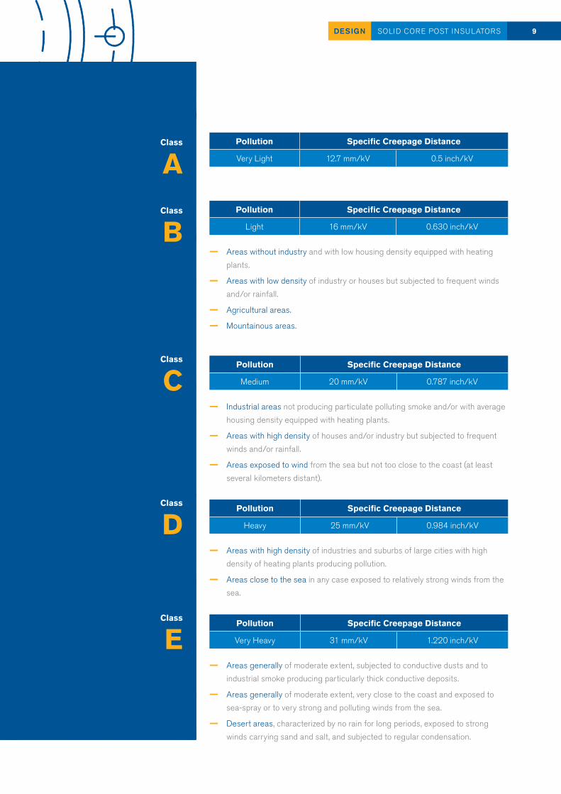
9DESIGN SOLID CORE POST INSULATORS
Pollution Specific Creepage Distance
Light 16 mm/kV 0.630 inch/kV
— Areas without industry and with low housing density equipped with heating plants.
— Areas with low density of industry or houses but subjected to frequent winds and/or rainfall.
— Agricultural areas.
— Mountainous areas.
Pollution Specific Creepage Distance
Very Light 12.7 mm/kV 0.5 inch/kV
Pollution Specific Creepage Distance
Medium 20 mm/kV 0.787 inch/kV
— Industrial areas not producing particulate polluting smoke and/or with average housing density equipped with heating plants.
— Areas with high density of houses and/or industry but subjected to frequent winds and/or rainfall.
— Areas exposed to wind from the sea but not too close to the coast (at least several kilometers distant).
Pollution Specific Creepage Distance
Heavy 25 mm/kV 0.984 inch/kV
— Areas with high density of industries and suburbs of large cities with high density of heating plants producing pollution.
— Areas close to the sea in any case exposed to relatively strong winds from the sea.
Pollution Specific Creepage Distance
Very Heavy 31 mm/kV 1.220 inch/kV
— Areas generally of moderate extent, subjected to conductive dusts and to industrial smoke producing particularly thick conductive deposits.
— Areas generally of moderate extent, very close to the coast and exposed to sea-spray or to very strong and polluting winds from the sea.
— Desert areas, characterized by no rain for long periods, exposed to strong winds carrying sand and salt, and subjected to regular condensation.
Class
B
Class
A
Class
C
Class
D
Class
E
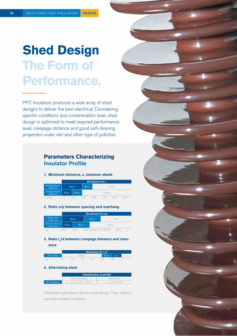
Shed Design The Form of Performance.PPC Insulators produces a wide array of shed designs to deliver the best electrical. Considering specific conditions and contamination level, shed design is optimized to meet required performance level, creepage distance and good self-cleaning properties under rain and other type of pollution.
10 DESIGNSOLID CORE POST INSULATORS
Parameters Characterizing Insulator Profile
1. Minimum distance, c, between sheds
2. Ratio s/p between spacing and overhang
3. Ratio ld/d between creepage distance and clear-
ance
4. Alternating shed
Parameters give basic rules to assist design. They relate to
vertically installed insulators.
Deviations for cInsulator lenght
>550 mm Major Minor None
Insulator lenght ≤550 mm Major Minor None
c (mm) 15 20 25 30 35 40 45
Deviations for ld/dAll profiles None Minor Major
ld/d 1 2 3 4 5 6 7
Classification of profileNon-alternating Alternating
All insulators p1 = p2 or p1 - p2 < 15 mm p1 - p2 ≥ 15 mm
Deviations for s/pSheds with under ribs Major Minor None
Sheds without under ribs Major Minor None
s/p 0,4 0,5 0,6 0,65 0,7 0,75 0,8 0,9 1
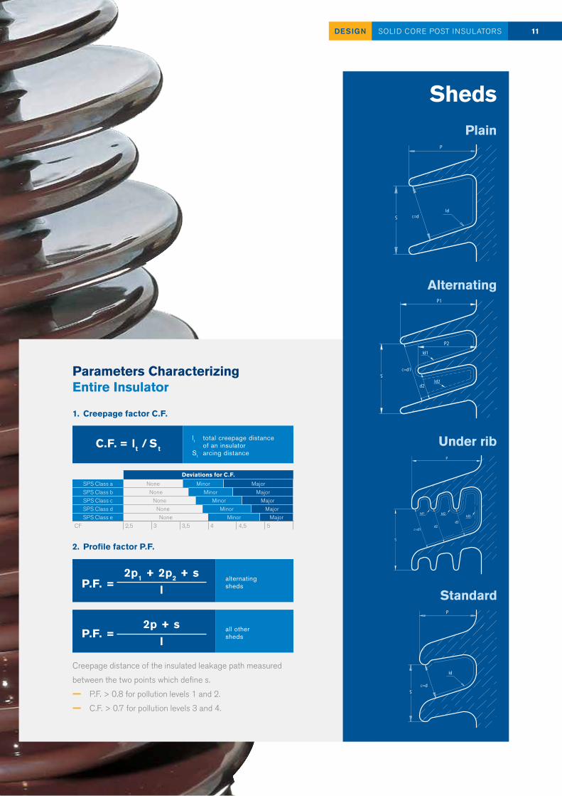
Parameters Characterizing Entire Insulator
1. Creepage factor C.F.
2. Profile factor P.F.
Creepage distance of the insulated leakage path measured
between the two points which define s.
— P.F. > 0.8 for pollution levels 1 and 2.
— C.F. > 0.7 for pollution levels 3 and 4.
C.F. = lt / St
lt total creepage distance of an insulatorSt arcing distance
P.F. =2p1 + 2p2 + s
lalternating sheds
P.F. =2p + s
lall othersheds
Deviations for C.F.SPS Class a None Minor MajorSPS Class b None Minor MajorSPS Class c None Minor MajorSPS Class d None Minor MajorSPS Class e None Minor Major
CF 2,5 3 3,5 4 4,5 5
Alternating
Under rib
ShedsPlain
Standard
11DESIGN SOLID CORE POST INSULATORS
Insulating Material The Making of the Quality.
12 DESIGNSOLID CORE POST INSULATORS
Fitt
ings
The insulator body of the unit is made from high quality aluminium oxide porcelain, C130 or C120, which conforms to standard IEC60672. Glazing provides a dirt repellent surface. Glazing is normally brown in colour, though Munsell grey can also be provided upon request.
Fittings are made in malleable cast iron according to
standard EN1562 or spheroidal graphite cast iron accord-
ing to standard EN1563. All fittings are hot dip galvanized
according to standard EN ISO 1461 with a zinc weight of
min. 600 g/m2 (min. 85 μm) as average value. The following
table shows the standard dimensions for fittings according
to IEC60273.
Fitt
ings
with
oth
er d
imen
sion
s
13DESIGN SOLID CORE POST INSULATORS
Pitch circle diameter p.c.d. d1
Depth of the tapped blind holes h2
Number of holes n Bolt holes tapped d2 Bolt holes plain Ø d2
Nominal maximum diameter of mount-
ing face d3
mm mm - - mm mm
76 12 4 M12 - 115
127 18 (22) 4 M16 - 165
178 4 - 18 225
200 4 - 18 245
225 4 - 18 270
254 8 - 18 300
275 8 - 18 320
300 8 - 18 345
325 8 - 18 370
356 8 - 18 400
375 20 8 - 18 420
(e.g., for operation rod columns) can be supplied on request.
Threads are generally tapped after hot dip galvanizing; for shipment and storage, the threads will be protected by a protective layer and/or special plastic plugs.
NOTE: Multiple unit insulator columns will be delivered with hardware (bolts, nuts and spring washers) for the interconnection of the insulator units.
ProductionLeading-Edge Craftmanship.
Tolerances of Dimensions, Form and Position
The tolerances are in accordance
with the standards IEC60168 and
IEC60273.
14 DESIGNSOLID CORE POST INSULATORS
Tested Items Type Test Sample Test
Routine Test
Dry lightning impulse withstand voltage test N
Wet switiching impulse withstand voltage test N1
Wet power frequency withstand voltage test N
Mechanical failing load test Bending strength N N
Verification of dimensions N
Temperature cycles test N
Porosity test N2
Galvanising test N
Visual inspection N
Mechanical test (Bending) N3
Inspection and Testing
Inspections and tests after firing
are made according to standard
IEC60168.
1. Applicable only to post
insulators for use on systems
with highest voltage for
equipment above 245 kV
2. In agreement with Customer
3. Insulators with height >770 mm

15DESIGN SOLID CORE POST INSULATORS
Cem
entin
g The fittings are assembled to the
porcelain body with a Portland base
mortar as standard. A bituminous
coating is applied on the porcelain
and the fittings to compensate for
the difference in thermal expan-
sion. This is especially important for
extreme weather applications.
Mar
king
Each insulator carries the trademark
of the PPC Insulators, the trademark
of the manufacturing factory, type
designation (reference number), date
of manufacture and a serial number.
Key Features CompetitiveAdvantages.
16 ADVANTAGESSOLID CORE POST INSULATORS
High strength aluminium oxide porcelain body — highest strength to weight ratio
— high compression and torsion strength
— minimum deflection
— high resistance to vandalism
— resistant to salt pollution
Below 1 % of quartzware residue — free of internal stresses
— highest structure rigidiy
— minimum porosity
— lowest maintenance costs
No measurable aging — high resistance to termal stress
— high resistance to temperature variations
— minimum total life cycle costs
High performance consistency — routine test load at 70 % of the min. failing load
— low surface leakage current
— separated electrical and mechanical zones
— good self-cleaning properties
— good insulation performance under pollution
— ultrasonic mechanical soundness inspection
Puncture proof — The theoretical puncture path through the porcelain body is
almost equal to the dry arcing distance. Since porcelain has several times the dielectric breakdown strength of air, flashover, if any, always occurs in the air outside the porcelain body
17ADVANTAGES SOLID CORE POST INSULATORS
Pro
duct
ion
and
Pro
duct
Tab
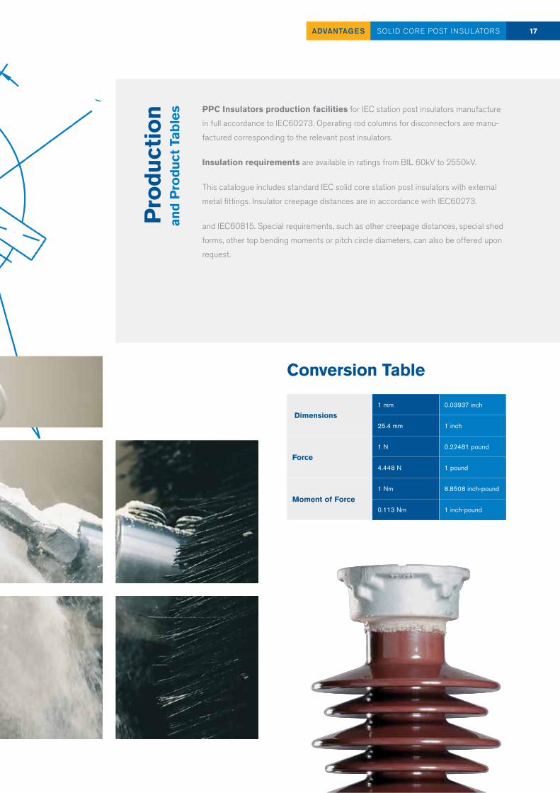
les PPC Insulators production facilities for IEC station post insulators manufacture
in full accordance to IEC60273. Operating rod columns for disconnectors are manu-
factured corresponding to the relevant post insulators.
Insulation requirements are available in ratings from BIL 60kV to 2550kV.
This catalogue includes standard IEC solid core station post insulators with external
metal fittings. Insulator creepage distances are in accordance with IEC60273.
and IEC60815. Special requirements, such as other creepage distances, special shed
forms, other top bending moments or pitch circle diameters, can also be offered upon
request.
Dimensions1 mm 0.03937 inch
25.4 mm 1 inch
Force1 N 0.22481 pound
4.448 N 1 pound
Moment of Force1 Nm 8.8508 inch-pound
0.113 Nm 1 inch-pound
Conversion Table
18 SERVICES
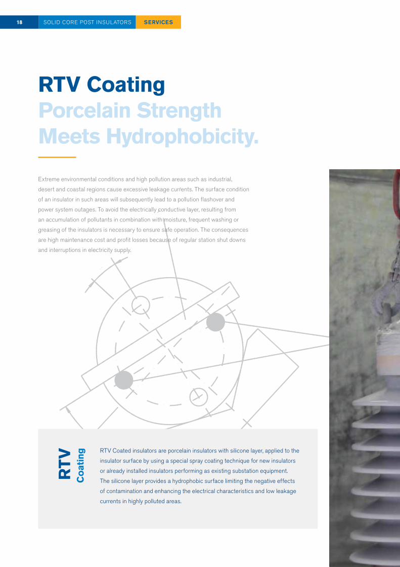
RTV Coating Porcelain Strength Meets Hydrophobicity.
Extreme environmental conditions and high pollution areas such as industrial,
desert and coastal regions cause excessive leakage currents. The surface condition
of an insulator in such areas will subsequently lead to a pollution flashover and
power system outages. To avoid the electrically conductive layer, resulting from
an accumulation of pollutants in combination with moisture, frequent washing or
greasing of the insulators is necessary to ensure safe operation. The consequences
are high maintenance cost and profit losses because of regular station shut downs
and interruptions in electricity supply.
SOLID CORE POST INSULATORS
RTV
Coa
ting RTV Coated insulators are porcelain insulators with silicone layer, applied to the
insulator surface by using a special spray coating technique for new insulators
or already installed insulators performing as existing substation equipment.
The silicone layer provides a hydrophobic surface limiting the negative effects
of contamination and enhancing the electrical characteristics and low leakage
currents in highly polluted areas.

SERVICES 19SOLID CORE POST INSULATORS
Benefits of RTV Coating
— Excellent self-cleaning characteristics
— Long-term hydrophobicity
— Suppression of leakage current, discharges and pollution flashover
— Reduced maintenance expenditures
— Facilitated cleaning in case of extreme pollution deposition
— RTV coated surfaces withstand high pressure jet washing
— Minimum 15 years lifecycle
— Nontoxic and environmental friendly material
20 BIL 60-95 KVSOLID CORE POST INSULATORS
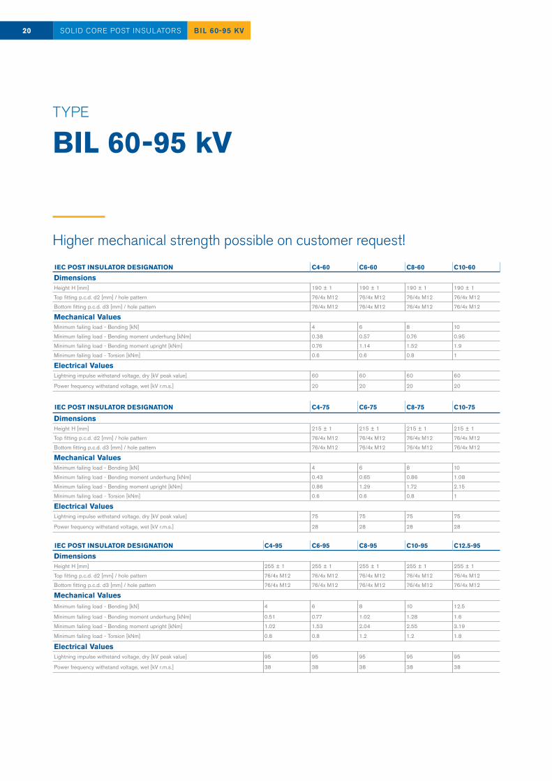
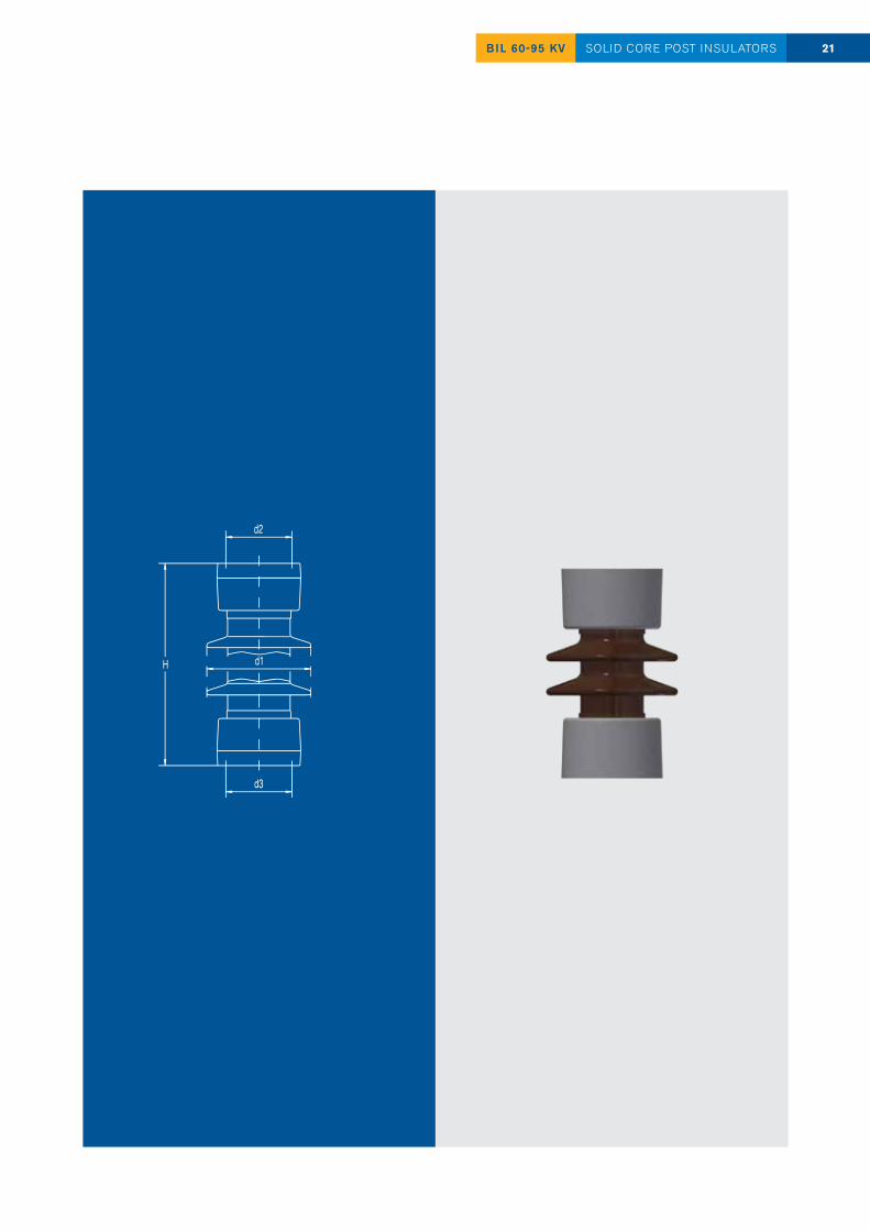
TYPE BIL 60-95 kV
IEC POST INSULATOR DESIGNATION C4-60 C6-60 C8-60 C10-60
DimensionsHeight H [mm] 190 ± 1 190 ± 1 190 ± 1 190 ± 1
Top fitting p.c.d. d2 [mm] / hole pattern 76/4x M12 76/4x M12 76/4x M12 76/4x M12
Bottom fitting p.c.d. d3 [mm] / hole pattern 76/4x M12 76/4x M12 76/4x M12 76/4x M12
Mechanical ValuesMinimum failing load - Bending [kN] 4 6 8 10
Minimum failing load - Bending moment underhung [kNm] 0.38 0.57 0.76 0.95
Minimum failing load - Bending moment upright [kNm] 0.76 1.14 1.52 1.9
Minimum failing load - Torsion [kNm] 0.6 0.6 0.8 1
Electrical ValuesLightning impulse withstand voltage, dry [kV peak value] 60 60 60 60
Power frequency withstand voltage, wet [kV r.m.s.] 20 20 20 20
IEC POST INSULATOR DESIGNATION C4-75 C6-75 C8-75 C10-75
DimensionsHeight H [mm] 215 ± 1 215 ± 1 215 ± 1 215 ± 1
Top fitting p.c.d. d2 [mm] / hole pattern 76/4x M12 76/4x M12 76/4x M12 76/4x M12
Bottom fitting p.c.d. d3 [mm] / hole pattern 76/4x M12 76/4x M12 76/4x M12 76/4x M12
Mechanical ValuesMinimum failing load - Bending [kN] 4 6 8 10
Minimum failing load - Bending moment underhung [kNm] 0.43 0.65 0.86 1.08
Minimum failing load - Bending moment upright [kNm] 0.86 1.29 1.72 2.15
Minimum failing load - Torsion [kNm] 0.6 0.6 0.8 1
Electrical ValuesLightning impulse withstand voltage, dry [kV peak value] 75 75 75 75
Power frequency withstand voltage, wet [kV r.m.s.] 28 28 28 28
IEC POST INSULATOR DESIGNATION C4-95 C6-95 C8-95 C10-95 C12.5-95
DimensionsHeight H [mm] 255 ± 1 255 ± 1 255 ± 1 255 ± 1 255 ± 1
Top fitting p.c.d. d2 [mm] / hole pattern 76/4x M12 76/4x M12 76/4x M12 76/4x M12 76/4x M12
Bottom fitting p.c.d. d3 [mm] / hole pattern 76/4x M12 76/4x M12 76/4x M12 76/4x M12 76/4x M12
Mechanical ValuesMinimum failing load - Bending [kN] 4 6 8 10 12.5
Minimum failing load - Bending moment underhung [kNm] 0.51 0.77 1.02 1.28 1.6
Minimum failing load - Bending moment upright [kNm] 1.02 1.53 2.04 2.55 3.19
Minimum failing load - Torsion [kNm] 0.8 0.8 1.2 1.2 1.8
Electrical ValuesLightning impulse withstand voltage, dry [kV peak value] 95 95 95 95 95
Power frequency withstand voltage, wet [kV r.m.s.] 38 38 38 38 38
Higher mechanical strength possible on customer request!
21BIL 60-95 KV SOLID CORE POST INSULATORS

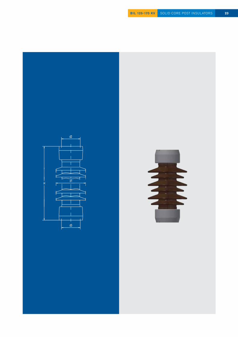
TYPE BIL 125-170 kV
IEC POST INSULATOR DESIGNATION C4-125 C6-125 C8-125 C10-125 C12.5-125
DimensionsHeight H [mm] 305 ± 1 305 ± 1 305 ± 1 305 ± 1 305 ± 1
Max. nom. diameter of insulating part d1 [mm] 170 180 190 190 200
Top fitting p.c.d. d2 [mm] / hole pattern 76/4x M12 76/4x M12 76/4x M12 76/4x M12 76/4x M12
Bottom fitting p.c.d. d3 [mm] / hole pattern 76/4x M12 76/4x M12 76/4x M12 76/4x M12 76/4x M12
Mechanical ValuesMinimum failing load - Bending [kN] 4 6 8 10 12.5
Minimum failing load - Bending moment underhung [kNm] 0.61 0.92 1.22 1.53 1.91
Minimum failing load - Bending moment upright [kNm] 1.22 1.83 2.44 3.05 3.82
Minimum failing load - Torsion [kNm] 0.8 0.8 1.2 1.2 2
Electrical ValuesLightning impulse withstand voltage, dry [kV peak value] 125 125 125 125 125
Power frequency withstand voltage, wet [kV r.m.s.] 50 50 50 50 50
IEC POST INSULATOR DESIGNATION C4-150 C6-150 C8-150 C10-150 C12.5-150
DimensionsHeight H [mm] 355 ± 1 355 ± 1 355 ± 1 355 ± 1 355 ± 1
Max. nom. diameter of insulating part d1 [mm] 175 190 190 195 205
Top fitting p.c.d. d2 [mm] / hole pattern 76/4x M12 76/4x M12 76/4x M12 76/4x M12 76/4x M12
Bottom fitting p.c.d. d3 [mm] / hole pattern 76/4x M12 76/4x M12 76/4x M12 76/4x M12 76/4x M12
Mechanical ValuesMinimum failing load - Bending [kN] 4 6 8 10 12.5
Minimum failing load - Bending moment underhung [kNm] 0.71 1.07 1.42 1.78 2.22
Minimum failing load - Bending moment upright [kNm] 1.42 2.13 2.84 3.55 4.44
Minimum failing load - Torsion [kNm] 1 1.2 1.5 1.8 2.5
Electrical ValuesLightning impulse withstand voltage, dry [kV peak value] 150 150 150 150 150
Power frequency withstand voltage, wet [kV r.m.s.] 50 50 50 50 50
IEC POST INSULATOR DESIGNATION C4-170 C6-170 C8-170 C10-170 C12.5-170
DimensionsHeight H [mm] 445 ± 1 445 ± 1 445 ± 1 445 ± 1 445 ± 1Max. nom. diameter of insulating part d1 [mm] 180 190 195 205 210Top fitting p.c.d. d2 [mm] / hole pattern 76/4x M12 76/4x M12 76/4x M12 76/4x M12 127/4x M16Bottom fitting p.c.d. d3 [mm] / hole pattern 76/4x M12 76/4x M12 76/4x M12 76/4x M12 127/4x M16
Mechanical ValuesMinimum failing load - Bending [kN] 4 6 8 10 12.5Minimum failing load - Bending moment underhung [kNm] 0.89 1.34 1.78 2.23 2.79Minimum failing load - Bending moment upright [kNm] 1.78 2.67 3.56 4.45 5.57Minimum failing load - Torsion [kNm] 1.2 1.5 2 2.5 3
Electrical ValuesLightning impulse withstand voltage, dry [kV peak value] 170 170 170 170 170
Power frequency withstand voltage, wet [kV r.m.s.] 70 70 70 70 70
22 BIL 125-170 KVSOLID CORE POST INSULATORS
Higher mechanical strength possible on customer request!
23BIL 125-170 KV SOLID CORE POST INSULATORS
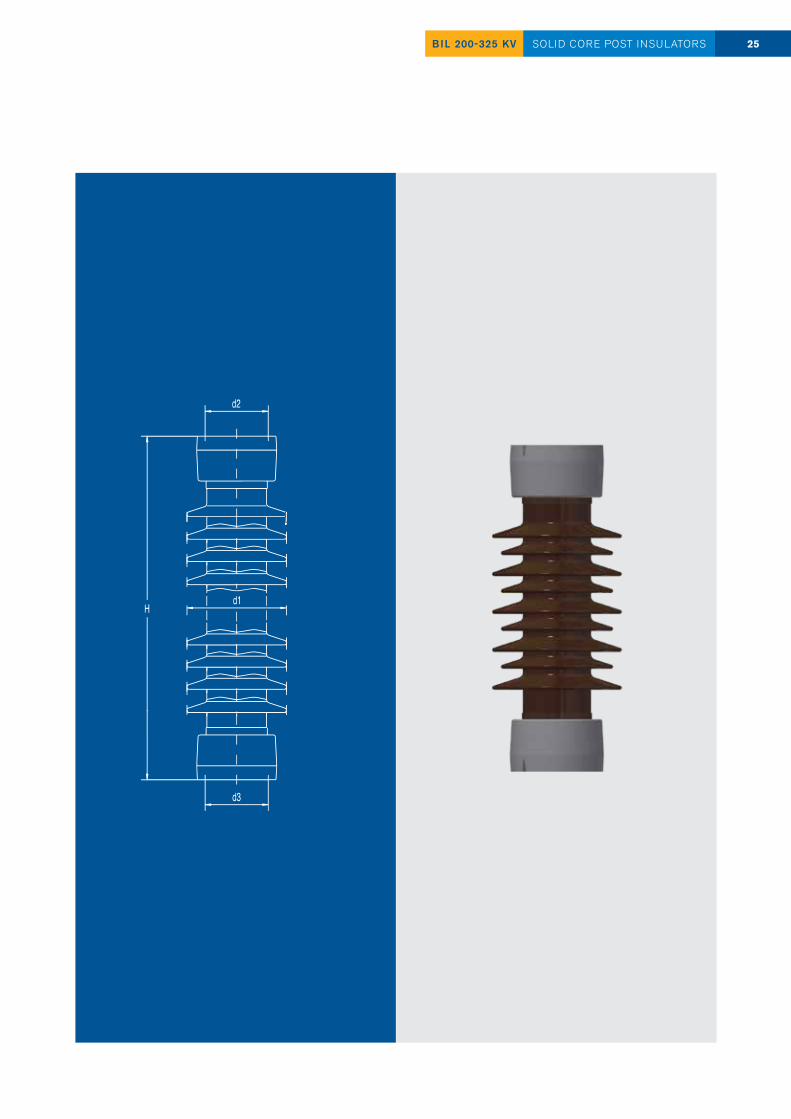
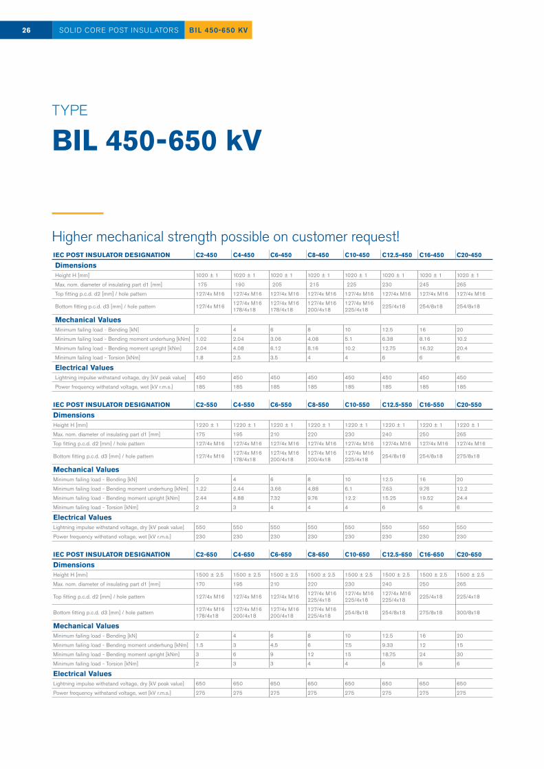
TYPE BIL 200-325 kV
IEC POST INSULATOR DESIGNATION C4-200 C6-200 C8-200 C10-200 C12.5-200
DimensionsHeight H [mm] 475 ± 1 475 ± 1 475 ± 1 475 ± 1 475 ± 1
Max. nom. diameter of insulating part d1 [mm] 180 190 200 205 215
Top fitting p.c.d. d2 [mm] / hole pattern 76/4x M12 76/4x M12 76/4x M12 76/4x M12 127/4x M16
Bottom fitting p.c.d. d3 [mm] / hole pattern 76/4x M12 76/4x M12 76/4x M12 76/4x M12 127/4x M16
Mechanical ValuesMinimum failing load - Bending [kN] 4 6 8 10 12.5
Minimum failing load - Bending moment underhung [kNm] 0.95 1.43 1.9 2.38 2.97
Minimum failing load - Bending moment upright [kNm] 1.9 2.85 3.8 4.75 5.94
Minimum failing load - Torsion [kNm] 1.2 1.8 2 2.5 3
Electrical ValuesLightning impulse withstand voltage, dry [kV peak value] 200 200 200 200 200
Power frequency withstand voltage, wet [kV r.m.s.] 70 70 70 70 70
IEC POST INSULATOR DESIGNATION C4-250 C6-250 C8-250 C10-250 C12.5-250
DimensionsHeight H [mm] 560 ± 1 560 ± 1 560 ± 1 560 ± 1 560 ± 1
Max. nom. diameter of insulating part d1 [mm] 175 185 200 200 200
Top fitting p.c.d. d2 [mm] / hole pattern 76/4x M12 127/4x M16
76/4x M12 127/4x M16 127/4x M16 127/4x M16 127/4x M16
Bottom fitting p.c.d. d3 [mm] / hole pattern 76/4x M12 127/4x M16
76/4x M12 127/4x M16 127/4x M16 127/4x M16 127/4x M16
Mechanical ValuesMinimum failing load - Bending [kN] 4 6 8 10 12.5
Minimum failing load - Bending moment underhung [kNm] 1.12 1.68 2.24 2.8 3.5
Minimum failing load - Bending moment upright [kNm] 2.24 3.36 4.48 5.6 7
Minimum failing load - Torsion [kNm] 1.8 2 2.5 3 4
Electrical ValuesLightning impulse withstand voltage, dry [kV peak value] 250 250 250 250 250
Power frequency withstand voltage, wet [kV r.m.s.] 95 95 95 95 95
IEC POST INSULATOR DESIGNATION C2-325 C4-325 C6-325 C8-325 C10-325 C12.5-325 C16-325 C20-325
DimensionsHeight H [mm] 770 ± 1 770 ± 1 770 ± 1 770 ± 1 770 ± 1 770 ± 1 770 ± 1 770 ± 1
Max. nom. diameter of insulating part d1 [mm] 165 185 195 205 210 220 230 240
Top fitting p.c.d. d2 [mm] / hole pattern 127/4x M16 127/4x M16 127/4x M16 127/4x M16 127/4x M16 127/4x M16 127/4x M16 127/4x M16
Bottom fitting p.c.d. d3 [mm] / hole pattern 127/4x M16 127/4x M16 127/4x M16 127/4x M16 127/4x M16 127/4x M16 225/4x18 254/8x18
Mechanical ValuesMinimum failing load - Bending [kN] 2 4 6 8 10 12.5 16 20
Minimum failing load - Bending moment underhung [kNm] 0.77 1.54 2.31 3.08 3.85 4.82 6.16 7.7
Minimum failing load - Bending moment upright [kNm] 1.54 3.08 4.62 6.16 7.7 9.63 12.32 15.4
Minimum failing load - Torsion [kNm] 1.2 2 2.5 3 4 4 5 6
Electrical ValuesLightning impulse withstand voltage, dry [kV peak value] 325 325 325 325 325 325 325 325
Power frequency withstand voltage, wet [kV r.m.s.] 140 140 140 140 140 140 140 140
24 BIL 200-325 KVSOLID CORE POST INSULATORS
Higher mechanical strength possible on customer request!
25BIL 200-325 KV SOLID CORE POST INSULATORS
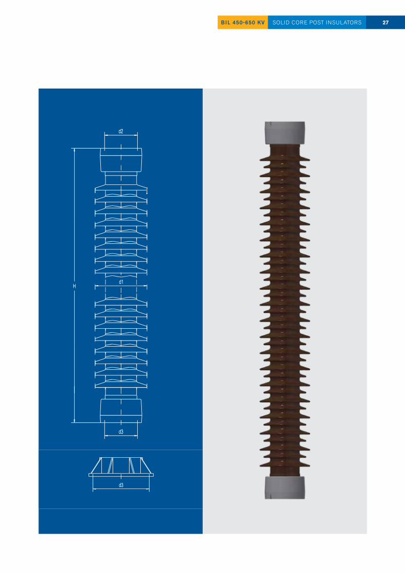
TYPE BIL 450-650 kV
IEC POST INSULATOR DESIGNATION C2-650 C4-650 C6-650 C8-650 C10-650 C12.5-650 C16-650 C20-650
DimensionsHeight H [mm] 1500 ± 2.5 1500 ± 2.5 1500 ± 2.5 1500 ± 2.5 1500 ± 2.5 1500 ± 2.5 1500 ± 2.5 1500 ± 2.5
Max. nom. diameter of insulating part d1 [mm] 170 195 210 220 230 240 250 265
Top fitting p.c.d. d2 [mm] / hole pattern 127/4x M16 127/4x M16 127/4x M16 127/4x M16225/4x18
127/4x M16225/4x18
127/4x M16225/4x18 225/4x18 225/4x18
Bottom fitting p.c.d. d3 [mm] / hole pattern 127/4x M16178/4x18
127/4x M16200/4x18
127/4x M16200/4x18
127/4x M16225/4x18 254/8x18 254/8x18 275/8x18 300/8x18
Mechanical ValuesMinimum failing load - Bending [kN] 2 4 6 8 10 12.5 16 20
Minimum failing load - Bending moment underhung [kNm] 1.5 3 4.5 6 7.5 9.33 12 15
Minimum failing load - Bending moment upright [kNm] 3 6 9 12 15 18.75 24 30
Minimum failing load - Torsion [kNm] 2 3 3 4 4 6 6 6
Electrical ValuesLightning impulse withstand voltage, dry [kV peak value] 650 650 650 650 650 650 650 650
Power frequency withstand voltage, wet [kV r.m.s.] 275 275 275 275 275 275 275 275
IEC POST INSULATOR DESIGNATION C2-550 C4-550 C6-550 C8-550 C10-550 C12.5-550 C16-550 C20-550
DimensionsHeight H [mm] 1220 ± 1 1220 ± 1 1220 ± 1 1220 ± 1 1220 ± 1 1220 ± 1 1220 ± 1 1220 ± 1
Max. nom. diameter of insulating part d1 [mm] 175 195 210 220 230 240 250 265
Top fitting p.c.d. d2 [mm] / hole pattern 127/4x M16 127/4x M16 127/4x M16 127/4x M16 127/4x M16 127/4x M16 127/4x M16 127/4x M16
Bottom fitting p.c.d. d3 [mm] / hole pattern 127/4x M16 127/4x M16178/4x18
127/4x M16200/4x18
127/4x M16200/4x18
127/4x M16225/4x18 254/8x18 254/8x18 275/8x18
Mechanical ValuesMinimum failing load - Bending [kN] 2 4 6 8 10 12.5 16 20
Minimum failing load - Bending moment underhung [kNm] 1.22 2.44 3.66 4.88 6.1 7.63 9.76 12.2
Minimum failing load - Bending moment upright [kNm] 2.44 4.88 7.32 9.76 12.2 15.25 19.52 24.4
Minimum failing load - Torsion [kNm] 2 3 4 4 4 6 6 6
Electrical ValuesLightning impulse withstand voltage, dry [kV peak value] 550 550 550 550 550 550 550 550
Power frequency withstand voltage, wet [kV r.m.s.] 230 230 230 230 230 230 230 230
IEC POST INSULATOR DESIGNATION C2-450 C4-450 C6-450 C8-450 C10-450 C12.5-450 C16-450 C20-450
DimensionsHeight H [mm] 1020 ± 1 1020 ± 1 1020 ± 1 1020 ± 1 1020 ± 1 1020 ± 1 1020 ± 1 1020 ± 1
Max. nom. diameter of insulating part d1 [mm] 175 190 205 215 225 230 245 265
Top fitting p.c.d. d2 [mm] / hole pattern 127/4x M16 127/4x M16 127/4x M16 127/4x M16 127/4x M16 127/4x M16 127/4x M16 127/4x M16
Bottom fitting p.c.d. d3 [mm] / hole pattern 127/4x M16 127/4x M16 178/4x18
127/4x M16178/4x18
127/4x M16200/4x18
127/4x M16225/4x18 225/4x18 254/8x18 254/8x18
Mechanical ValuesMinimum failing load - Bending [kN] 2 4 6 8 10 12.5 16 20
Minimum failing load - Bending moment underhung [kNm] 1.02 2.04 3.06 4.08 5.1 6.38 8.16 10.2
Minimum failing load - Bending moment upright [kNm] 2.04 4.08 6.12 8.16 10.2 12.75 16.32 20.4
Minimum failing load - Torsion [kNm] 1.8 2.5 3.5 4 4 6 6 6
Electrical ValuesLightning impulse withstand voltage, dry [kV peak value] 450 450 450 450 450 450 450 450
Power frequency withstand voltage, wet [kV r.m.s.] 185 185 185 185 185 185 185 185
26 BIL 450-650 KVSOLID CORE POST INSULATORS
Higher mechanical strength possible on customer request!
27BIL 450-650 KV SOLID CORE POST INSULATORS
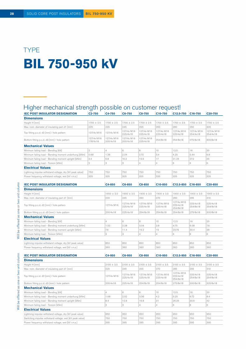
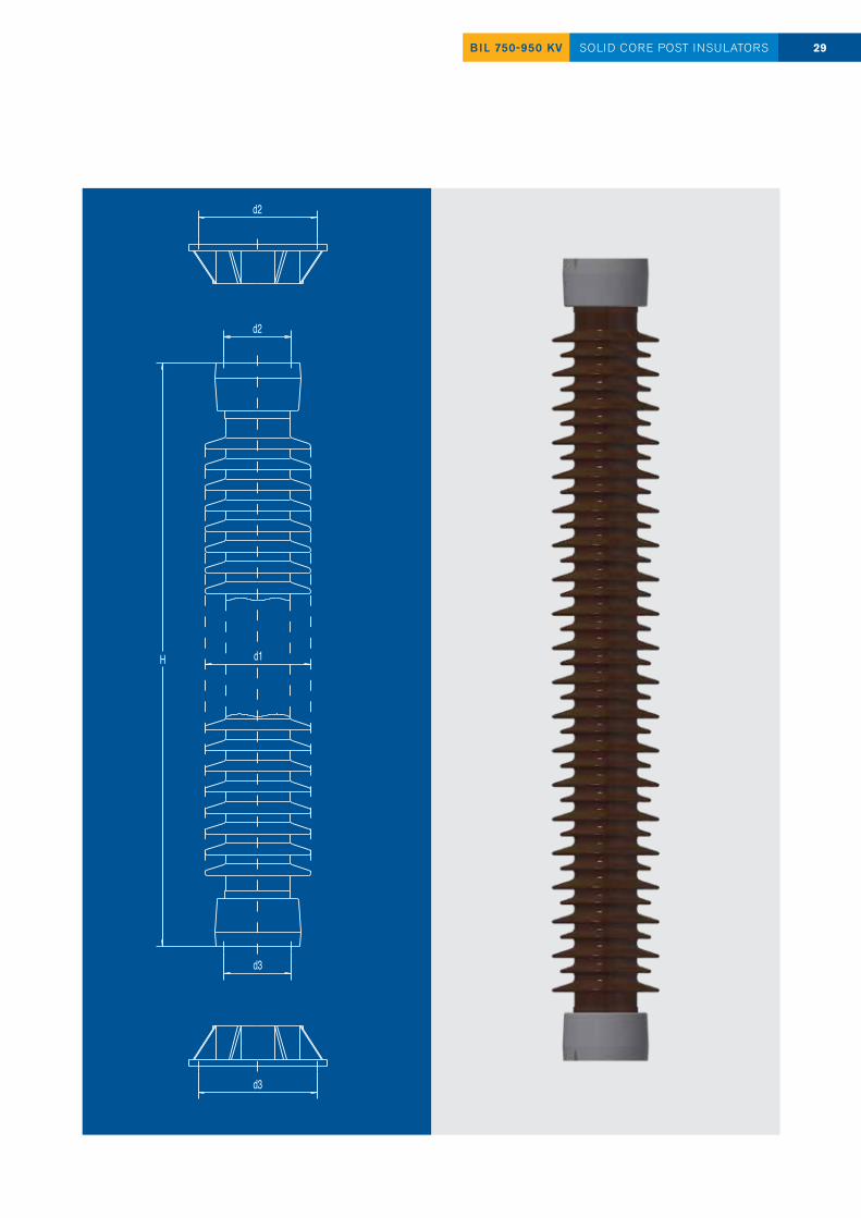
TYPE BIL 750-950 kV
IEC POST INSULATOR DESIGNATION C4-950 C6-950 C8-950 C10-950 C12.5-950 C16-950 C20-950
DimensionsHeight H [mm] 2100 ± 3.5 2100 ± 3.5 2100 ± 3.5 2100 ± 3.5 2100 ± 3.5 2100 ± 3.5 2100 ± 3.5
Max. nom. diameter of insulating part d1 [mm] 225 245 255 270 285 295 310
Top fitting p.c.d. d2 [mm] / hole pattern 127/4x M16 127/4x M16225/4x18
127/4x M16225/4x18
127/4x M16225/4x18
127/4x M16225/4x18254/8x18
225/4x18254/8x18
225/4x18254/8x18
Bottom fitting p.c.d. d3 [mm] / hole pattern 200/4x18 225/4x18 254/8x18 254/8x18 275/8x18 300/8x18 325/8x18
Mechanical ValuesMinimum failing load - Bending [kN] 4 6 8 10 12.5 16 20
Minimum failing load - Bending moment underhung [kNm] 1.68 2.52 3.36 4.2 5.25 6.72 8.4
Minimum failing load - Bending moment upright [kNm] 8.4 12.6 16.8 21 26.25 33.6 42
Minimum failing load - Torsion [kNm] 3 3 4 4 6 6 6
Electrical ValuesLightning impulse withstand voltage, dry [kV peak value] 950 950 950 950 950 950 950
Switching impulse withstand voltage, wet [kV peak value] 750 750 750 750 750 750 750
Power frequency withstand voltage, wet [kV r.m.s.] 395 395 395 395 395 395 395
IEC POST INSULATOR DESIGNATION C4-850 C6-850 C8-850 C10-850 C12.5-850 C16-850 C20-850
DimensionsHeight H [mm] 1900 ± 3.5 1900 ± 3.5 1900 ± 3.5 1900 ± 3.5 1900 ± 3.5 1900 ± 3.5 1900 ± 3.5
Max. nom. diameter of insulating part d1 [mm] 230 245 260 270 280 295 310
Top fitting p.c.d. d2 [mm] / hole pattern 127/4x M16 127/4x M16225/4x18
127/4x M16225/4x18
127/4x M16225/4x18
127/4x M16225/4x18254/8x18
225/4x18254/8x18
225/4x18254/8x18
Bottom fitting p.c.d. d3 [mm] / hole pattern 200/4x18 225/4x18 254/8x18 254/8x18 254/8x18 275/8x18 300/8x18
Mechanical ValuesMinimum failing load - Bending [kN] 4 6 8 10 12.5 16 20
Minimum failing load - Bending moment underhung [kNm] 1.52 2.28 3.04 3.8 4.75 6.08 7.6
Minimum failing load - Bending moment upright [kNm] 7.6 11.4 15.2 19 23.75 30.4 38
Minimum failing load - Torsion [kNm] 3 3 4 4 6 6 6
Electrical ValuesLightning impulse withstand voltage, dry [kV peak value] 850 850 850 850 850 850 850
Power frequency withstand voltage, wet [kV r.m.s.] 360 360 360 360 360 360 360
IEC POST INSULATOR DESIGNATION C2-750 C4-750 C6-750 C8-750 C10-750 C12.5-750 C16-750 C20-750
DimensionsHeight H [mm] 1700 ± 2.5 1700 ± 2.5 1700 ± 2.5 1700 ± 2.5 1700 ± 2.5 1700 ± 2.5 1700 ± 2.5 1700 ± 2.5
Max. nom. diameter of insulating part d1 [mm] 225 225 245 255 265 280 290 305
Top fitting p.c.d. d2 [mm] / hole pattern 127/4x M16 127/4x M16 127/4x M16225/4x18
127/4x M16225/4x18
127/4x M16225/4x18
127/4x M16225/4x18
127/4x M16254/4x18
127/4x M16254/4x18
Bottom fitting p.c.d. d3 [mm] / hole pattern 127/4x M16178/4x18
127/4x M16200/4x18
127/4x M16200/4x18
127/4x M16225/4x18 254/8x18 254/8x18 275/8x18 300/8x18
Mechanical ValuesMinimum failing load - Bending [kN] 2 4 6 8 10 12.5 16 20
Minimum failing load - Bending moment underhung [kNm] 0.68 1.36 2.04 2.72 3.4 4.25 5.44 6.8
Minimum failing load - Bending moment upright [kNm] 3.4 6.8 10.2 13.6 17 21.25 27.2 34
Minimum failing load - Torsion [kNm] 2 3 3 4 4 6 6 6
Electrical ValuesLightning impulse withstand voltage, dry [kV peak value] 750 750 750 750 750 750 750 750
Power frequency withstand voltage, wet [kV r.m.s.] 325 325 325 325 325 325 325 325
28 BIL 750-950 KVSOLID CORE POST INSULATORSW
ill be
off
ered
as
one
or tw
o un
it co
lum
nW
ill be
off
ered
as
one
or tw
o un
it co
lum
n
Higher mechanical strength possible on customer request!
29BIL 750-950 KV SOLID CORE POST INSULATORS
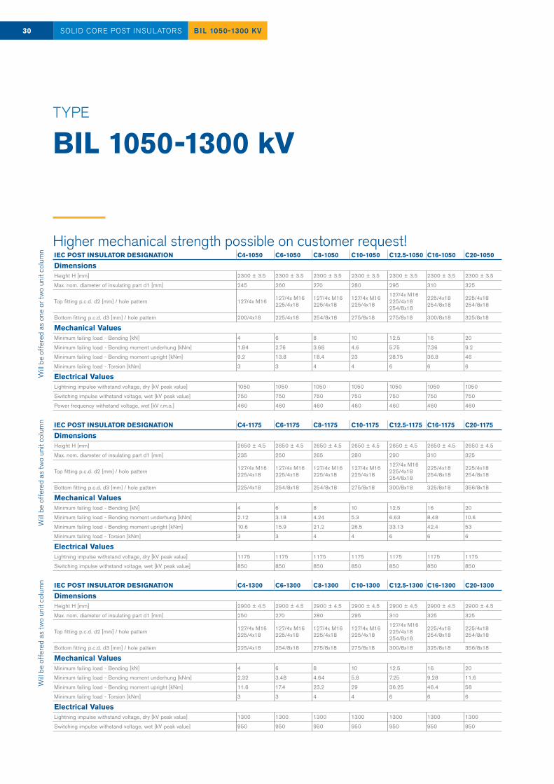
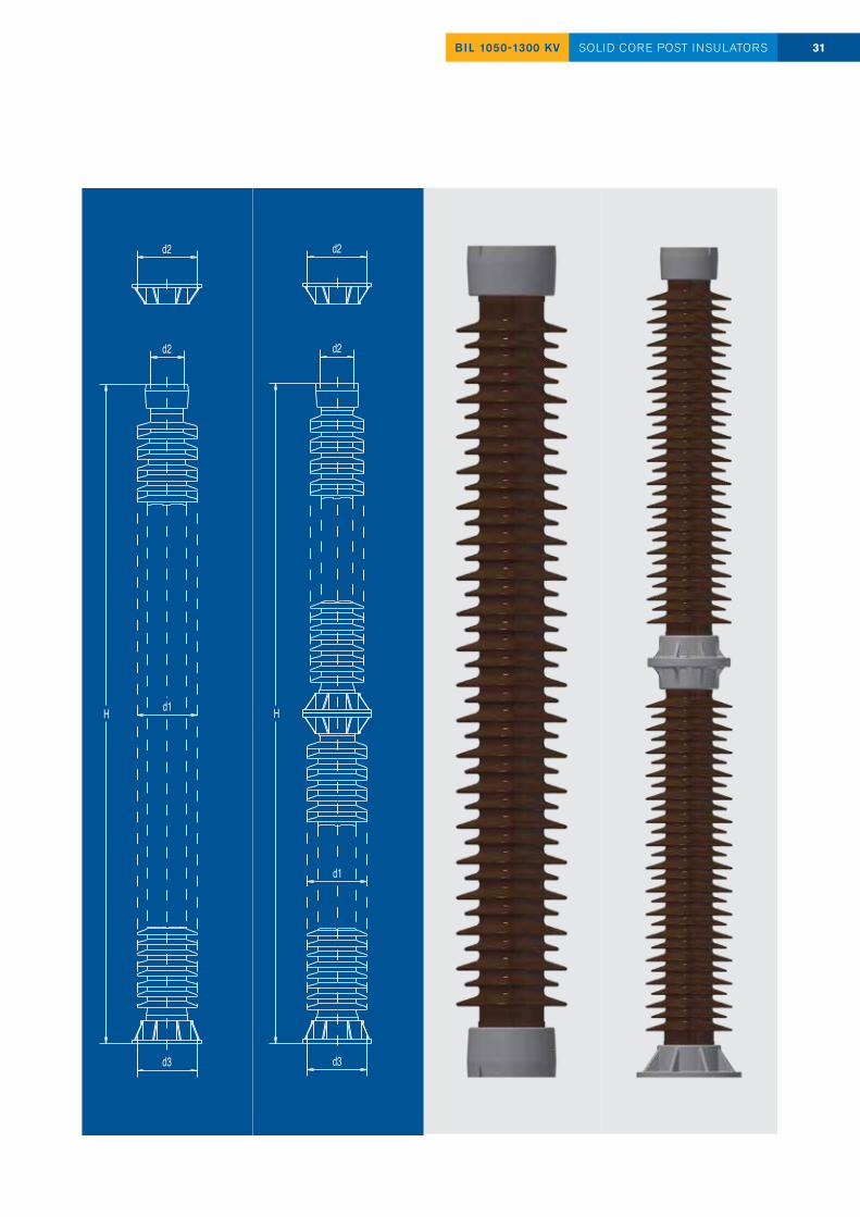
TYPE BIL 1050-1300 kV
IEC POST INSULATOR DESIGNATION C4-1300 C6-1300 C8-1300 C10-1300 C12.5-1300 C16-1300 C20-1300
DimensionsHeight H [mm] 2900 ± 4.5 2900 ± 4.5 2900 ± 4.5 2900 ± 4.5 2900 ± 4.5 2900 ± 4.5 2900 ± 4.5
Max. nom. diameter of insulating part d1 [mm] 250 270 280 295 310 325 325
Top fitting p.c.d. d2 [mm] / hole pattern 127/4x M16225/4x18
127/4x M16225/4x18
127/4x M16225/4x18
127/4x M16225/4x18
127/4x M16225/4x18254/8x18
225/4x18254/8x18
225/4x18254/8x18
Bottom fitting p.c.d. d3 [mm] / hole pattern 225/4x18 254/8x18 275/8x18 275/8x18 300/8x18 325/8x18 356/8x18
Mechanical ValuesMinimum failing load - Bending [kN] 4 6 8 10 12.5 16 20
Minimum failing load - Bending moment underhung [kNm] 2.32 3.48 4.64 5.8 7.25 9.28 11.6
Minimum failing load - Bending moment upright [kNm] 11.6 17.4 23.2 29 36.25 46.4 58
Minimum failing load - Torsion [kNm] 3 3 4 4 6 6 6
Electrical ValuesLightning impulse withstand voltage, dry [kV peak value] 1300 1300 1300 1300 1300 1300 1300
Switching impulse withstand voltage, wet [kV peak value] 950 950 950 950 950 950 950
IEC POST INSULATOR DESIGNATION C4-1175 C6-1175 C8-1175 C10-1175 C12.5-1175 C16-1175 C20-1175
DimensionsHeight H [mm] 2650 ± 4.5 2650 ± 4.5 2650 ± 4.5 2650 ± 4.5 2650 ± 4.5 2650 ± 4.5 2650 ± 4.5
Max. nom. diameter of insulating part d1 [mm] 235 250 265 280 290 310 325
Top fitting p.c.d. d2 [mm] / hole pattern 127/4x M16225/4x18
127/4x M16225/4x18
127/4x M16225/4x18
127/4x M16225/4x18
127/4x M16225/4x18254/8x18
225/4x18254/8x18
225/4x18254/8x18
Bottom fitting p.c.d. d3 [mm] / hole pattern 225/4x18 254/8x18 254/8x18 275/8x18 300/8x18 325/8x18 356/8x18
Mechanical ValuesMinimum failing load - Bending [kN] 4 6 8 10 12.5 16 20
Minimum failing load - Bending moment underhung [kNm] 2.12 3.18 4.24 5.3 6.63 8.48 10.6
Minimum failing load - Bending moment upright [kNm] 10.6 15.9 21.2 26.5 33.13 42.4 53
Minimum failing load - Torsion [kNm] 3 3 4 4 6 6 6
Electrical ValuesLightning impulse withstand voltage, dry [kV peak value] 1175 1175 1175 1175 1175 1175 1175
Switching impulse withstand voltage, wet [kV peak value] 850 850 850 850 850 850 850
IEC POST INSULATOR DESIGNATION C4-1050 C6-1050 C8-1050 C10-1050 C12.5-1050 C16-1050 C20-1050
DimensionsHeight H [mm] 2300 ± 3.5 2300 ± 3.5 2300 ± 3.5 2300 ± 3.5 2300 ± 3.5 2300 ± 3.5 2300 ± 3.5
Max. nom. diameter of insulating part d1 [mm] 245 260 270 280 295 310 325
Top fitting p.c.d. d2 [mm] / hole pattern 127/4x M16 127/4x M16225/4x18
127/4x M16225/4x18
127/4x M16225/4x18
127/4x M16225/4x18254/8x18
225/4x18254/8x18
225/4x18254/8x18
Bottom fitting p.c.d. d3 [mm] / hole pattern 200/4x18 225/4x18 254/8x18 275/8x18 275/8x18 300/8x18 325/8x18
Mechanical ValuesMinimum failing load - Bending [kN] 4 6 8 10 12.5 16 20
Minimum failing load - Bending moment underhung [kNm] 1.84 2.76 3.68 4.6 5.75 7.36 9.2
Minimum failing load - Bending moment upright [kNm] 9.2 13.8 18.4 23 28.75 36.8 46
Minimum failing load - Torsion [kNm] 3 3 4 4 6 6 6
Electrical ValuesLightning impulse withstand voltage, dry [kV peak value] 1050 1050 1050 1050 1050 1050 1050
Switching impulse withstand voltage, wet [kV peak value] 750 750 750 750 750 750 750
Power frequency withstand voltage, wet [kV r.m.s.] 460 460 460 460 460 460 460
30 BIL 1050-1300 KVSOLID CORE POST INSULATORSW
ill be
off
ered
as
one
or tw
o un
it co
lum
nW
ill be
off
ered
as
two
unit
colu
mn
Will
be o
ffer
ed a
s tw
o un
it co
lum
n
Higher mechanical strength possible on customer request!
31BIL 1050-1300 KV SOLID CORE POST INSULATORS
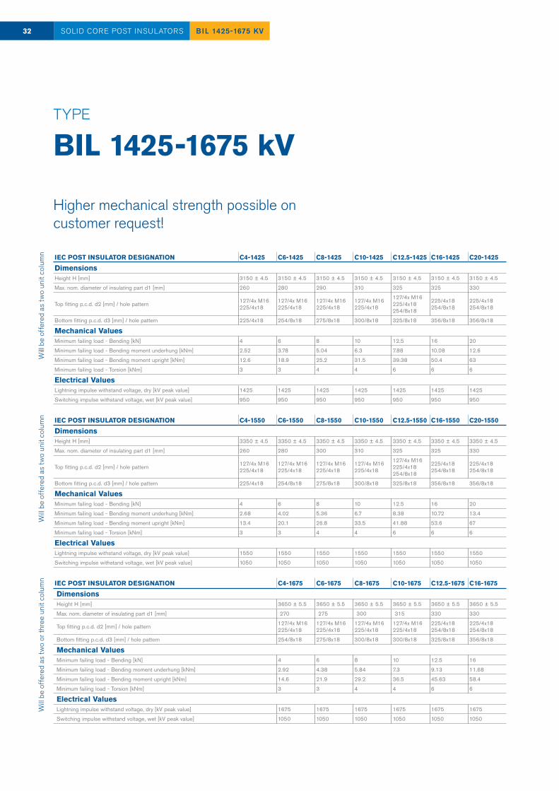
TYPE BIL 1425-1675 kV
Will
be o
ffer
ed a
s tw
o un
it co
lum
nW
ill be
off
ered
as
two
unit
colu
mn
Will
be o
ffer
ed a
s tw
o or
thre
e un
it co
lum
n IEC POST INSULATOR DESIGNATION C4-1675 C6-1675 C8-1675 C10-1675 C12.5-1675 C16-1675
DimensionsHeight H [mm] 3650 ± 5.5 3650 ± 5.5 3650 ± 5.5 3650 ± 5.5 3650 ± 5.5 3650 ± 5.5
Max. nom. diameter of insulating part d1 [mm] 270 275 300 315 330 330
Top fitting p.c.d. d2 [mm] / hole pattern 127/4x M16225/4x18
127/4x M16225/4x18
127/4x M16225/4x18
127/4x M16225/4x18
225/4x18254/8x18
225/4x18254/8x18
Bottom fitting p.c.d. d3 [mm] / hole pattern 254/8x18 275/8x18 300/8x18 300/8x18 325/8x18 356/8x18
Mechanical ValuesMinimum failing load - Bending [kN] 4 6 8 10 12.5 16
Minimum failing load - Bending moment underhung [kNm] 2.92 4.38 5.84 7.3 9.13 11.68
Minimum failing load - Bending moment upright [kNm] 14.6 21.9 29.2 36.5 45.63 58.4
Minimum failing load - Torsion [kNm] 3 3 4 4 6 6
Electrical ValuesLightning impulse withstand voltage, dry [kV peak value] 1675 1675 1675 1675 1675 1675
Switching impulse withstand voltage, wet [kV peak value] 1050 1050 1050 1050 1050 1050
IEC POST INSULATOR DESIGNATION C4-1550 C6-1550 C8-1550 C10-1550 C12.5-1550 C16-1550 C20-1550
DimensionsHeight H [mm] 3350 ± 4.5 3350 ± 4.5 3350 ± 4.5 3350 ± 4.5 3350 ± 4.5 3350 ± 4.5 3350 ± 4.5
Max. nom. diameter of insulating part d1 [mm] 260 280 300 310 325 325 330
Top fitting p.c.d. d2 [mm] / hole pattern 127/4x M16225/4x18
127/4x M16225/4x18
127/4x M16225/4x18
127/4x M16225/4x18
127/4x M16225/4x18254/8x18
225/4x18254/8x18
225/4x18254/8x18
Bottom fitting p.c.d. d3 [mm] / hole pattern 225/4x18 254/8x18 275/8x18 300/8x18 325/8x18 356/8x18 356/8x18
Mechanical ValuesMinimum failing load - Bending [kN] 4 6 8 10 12.5 16 20
Minimum failing load - Bending moment underhung [kNm] 2.68 4.02 5.36 6.7 8.38 10.72 13.4
Minimum failing load - Bending moment upright [kNm] 13.4 20.1 26.8 33.5 41.88 53.6 67
Minimum failing load - Torsion [kNm] 3 3 4 4 6 6 6
Electrical ValuesLightning impulse withstand voltage, dry [kV peak value] 1550 1550 1550 1550 1550 1550 1550
Switching impulse withstand voltage, wet [kV peak value] 1050 1050 1050 1050 1050 1050 1050
IEC POST INSULATOR DESIGNATION C4-1425 C6-1425 C8-1425 C10-1425 C12.5-1425 C16-1425 C20-1425
DimensionsHeight H [mm] 3150 ± 4.5 3150 ± 4.5 3150 ± 4.5 3150 ± 4.5 3150 ± 4.5 3150 ± 4.5 3150 ± 4.5
Max. nom. diameter of insulating part d1 [mm] 260 280 290 310 325 325 330
Top fitting p.c.d. d2 [mm] / hole pattern 127/4x M16225/4x18
127/4x M16225/4x18
127/4x M16225/4x18
127/4x M16225/4x18
127/4x M16225/4x18254/8x18
225/4x18254/8x18
225/4x18254/8x18
Bottom fitting p.c.d. d3 [mm] / hole pattern 225/4x18 254/8x18 275/8x18 300/8x18 325/8x18 356/8x18 356/8x18
Mechanical ValuesMinimum failing load - Bending [kN] 4 6 8 10 12.5 16 20
Minimum failing load - Bending moment underhung [kNm] 2.52 3.78 5.04 6.3 7.88 10.08 12.6
Minimum failing load - Bending moment upright [kNm] 12.6 18.9 25.2 31.5 39.38 50.4 63
Minimum failing load - Torsion [kNm] 3 3 4 4 6 6 6
Electrical ValuesLightning impulse withstand voltage, dry [kV peak value] 1425 1425 1425 1425 1425 1425 1425
Switching impulse withstand voltage, wet [kV peak value] 950 950 950 950 950 950 950
32 BIL 1425-1675 KVSOLID CORE POST INSULATORS
Higher mechanical strength possible on customer request!

33BIL 1425-1675 KV SOLID CORE POST INSULATORS
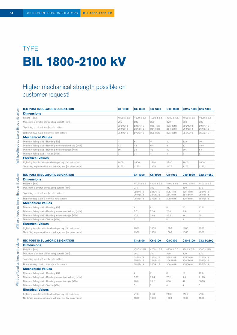
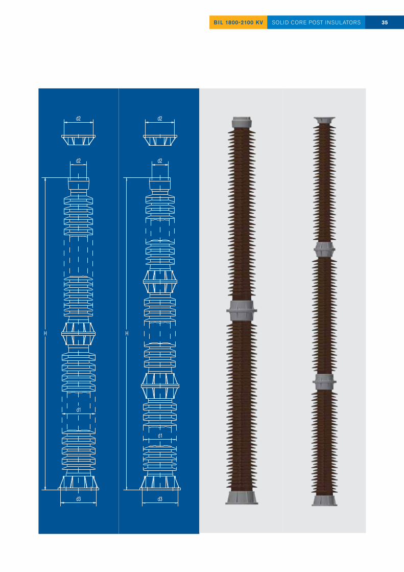
TYPE BIL 1800-2100 kV
IEC POST INSULATOR DESIGNATION C4-2100 C6-2100 C8-2100 C10-2100 C12.5-2100
DimensionsHeight H [mm] 4700 ± 5.5 4700 ± 5.5 4700 ± 5.5 4700 ± 5.5 4700 ± 5.5
Max. nom. diameter of insulating part d1 [mm] 280 300 320 320 330
Top fitting p.c.d. d2 [mm] / hole pattern 225/4x18254/8x18
225/4x18254/8x18
225/4x18254/8x18
225/4x18254/8x18
225/4x18254/8x18
Bottom fitting p.c.d. d3 [mm] / hole pattern 254/8x18 275/8x18 300/8x18 325/8x18 356/8x18
Mechanical ValuesMinimum failing load - Bending [kN] 4 6 8 10 12.5
Minimum failing load - Bending moment underhung [kNm] 3.76 5.64 7.52 9.4 11.75
Minimum failing load - Bending moment upright [kNm] 18.8 28.2 37.6 47 58.75
Minimum failing load - Torsion [kNm] 3 3 4 4 6
Electrical ValuesLightning impulse withstand voltage, dry [kV peak value] 2100 2100 2100 2100 2100
Switching impulse withstand voltage, wet [kV peak value] 1300 1300 1300 1300 1300
IEC POST INSULATOR DESIGNATION C4-1950 C6-1950 C8-1950 C10-1950 C12.5-1950
DimensionsHeight H [mm] 4400 ± 5.5 4400 ± 5.5 4400 ± 5.5 4400 ± 5.5 4400 ± 5.5
Max. nom. diameter of insulating part d1 [mm] 270 300 310 330 330
Top fitting p.c.d. d2 [mm] / hole pattern 225/4x18254/8x18
225/4x18254/8x18
225/4x18254/8x18
225/4x18254/8x18
225/4x18254/8x18
Bottom fitting p.c.d. d3 [mm] / hole pattern 254/8x18 275/8x18 300/8x18 325/8x18 356/8x18
Mechanical ValuesMinimum failing load - Bending [kN] 4 6 8 10 12.5
Minimum failing load - Bending moment underhung [kNm] 3.52 5.28 7.04 8.8 11
Minimum failing load - Bending moment upright [kNm] 17.6 26.4 35.2 44 55
Minimum failing load - Torsion [kNm] 3 3 4 4 6
Electrical ValuesLightning impulse withstand voltage, dry [kV peak value] 1950 1950 1950 1950 1950
Switching impulse withstand voltage, wet [kV peak value] 1300 1300 1300 1300 1300
IEC POST INSULATOR DESIGNATION C4-1800 C6-1800 C8-1800 C10-1800 C12.5-1800 C16-1800
DimensionsHeight H [mm] 4000 ± 5.5 4000 ± 5.5 4000 ± 5.5 4000 ± 5.5 4000 ± 5.5 4000 ± 5.5
Max. nom. diameter of insulating part d1 [mm] 260 280 300 320 320 330
Top fitting p.c.d. d2 [mm] / hole pattern 225/4x18254/8x18
225/4x18254/8x18
225/4x18254/8x18
225/4x18254/8x18
225/4x18254/8x18
225/4x18254/8x18
Bottom fitting p.c.d. d3 [mm] / hole pattern 254/4x18 275/8x18 300/8x18 325/8x18 356/8x18 356/8x18
Mechanical ValuesMinimum failing load - Bending [kN] 4 6 8 10 12.5 16
Minimum failing load - Bending moment underhung [kNm] 3.2 4.8 6.4 8 10 12.8
Minimum failing load - Bending moment upright [kNm] 16 24 32 40 50 64
Minimum failing load - Torsion [kNm] 3 3 4 4 6 6
Electrical ValuesLightning impulse withstand voltage, dry [kV peak value] 1800 1800 1800 1800 1800 1800
Switching impulse withstand voltage, wet [kV peak value] 1175 1175 1175 1175 1175 1175
34 BIL 1800-2100 KVSOLID CORE POST INSULATORSW
ill be
off
ered
as
two
or th
ree
unit
colu
mn
Will
be o
ffer
ed a
s tw
o or
thre
e un
it co
lum
nW
ill be
off
ered
as
thre
e un
it co
lum
n
Higher mechanical strength possible on customer request!
35BIL 1800-2100 KV SOLID CORE POST INSULATORS
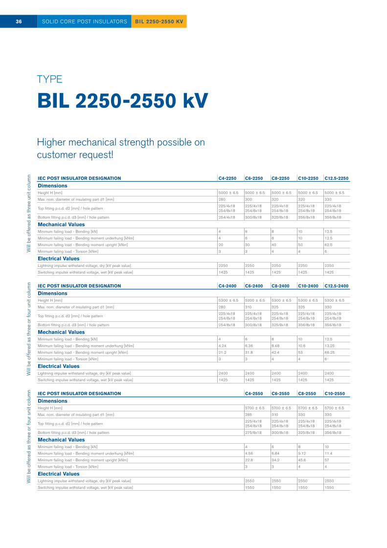
TYPE BIL 2250-2550 kV
IEC POST INSULATOR DESIGNATION C4-2550 C6-2550 C8-2550 C10-2550
DimensionsHeight H [mm] 5700 ± 6.5 5700 ± 6.5 5700 ± 6.5 5700 ± 6.5
Max. nom. diameter of insulating part d1 [mm] 285 310 330 330
Top fitting p.c.d. d2 [mm] / hole pattern 225/4x18254/8x18
225/4x18254/8x18
225/4x18254/8x18
225/4x18254/8x18
Bottom fitting p.c.d. d3 [mm] / hole pattern 275/8x18 300/8x18 325/8x18 356/8x18
Mechanical ValuesMinimum failing load - Bending [kN] 4 6 8 10
Minimum failing load - Bending moment underhung [kNm] 4.56 6.84 9.12 11.4
Minimum failing load - Bending moment upright [kNm] 22.8 34.2 45.6 57
Minimum failing load - Torsion [kNm] 3 3 4 4
Electrical ValuesLightning impulse withstand voltage, dry [kV peak value] 2550 2550 2550 2550
Switching impulse withstand voltage, wet [kV peak value] 1550 1550 1550 1550
IEC POST INSULATOR DESIGNATION C4-2400 C6-2400 C8-2400 C10-2400 C12.5-2400
DimensionsHeight H [mm] 5300 ± 6.5 5300 ± 6.5 5300 ± 6.5 5300 ± 6.5 5300 ± 6.5
Max. nom. diameter of insulating part d1 [mm] 280 310 325 325 330
Top fitting p.c.d. d2 [mm] / hole pattern 225/4x18254/8x18
225/4x18254/8x18
225/4x18254/8x18
225/4x18254/8x18
225/4x18254/8x18
Bottom fitting p.c.d. d3 [mm] / hole pattern 254/8x18 300/8x18 325/8x18 356/8x18 356/8x18
Mechanical ValuesMinimum failing load - Bending [kN] 4 6 8 10 12.5
Minimum failing load - Bending moment underhung [kNm] 4.24 6.36 8.48 10.6 13.25
Minimum failing load - Bending moment upright [kNm] 21.2 31.8 42.4 53 66.25
Minimum failing load - Torsion [kNm] 3 3 4 4 6
Electrical ValuesLightning impulse withstand voltage, dry [kV peak value] 2400 2400 2400 2400 2400
Switching impulse withstand voltage, wet [kV peak value] 1425 1425 1425 1425 1425
IEC POST INSULATOR DESIGNATION C4-2250 C6-2250 C8-2250 C10-2250 C12.5-2250
DimensionsHeight H [mm] 5000 ± 6.5 5000 ± 6.5 5000 ± 6.5 5000 ± 6.5 5000 ± 6.5
Max. nom. diameter of insulating part d1 [mm] 280 300 320 320 330
Top fitting p.c.d. d2 [mm] / hole pattern 225/4x18254/8x18
225/4x18254/8x18
225/4x18254/8x18
225/4x18254/8x18
225/4x18254/8x18
Bottom fitting p.c.d. d3 [mm] / hole pattern 254/4x18 300/8x18 325/8x18 356/8x18 356/8x18
Mechanical ValuesMinimum failing load - Bending [kN] 4 6 8 10 12.5
Minimum failing load - Bending moment underhung [kNm] 4 6 8 10 12.5
Minimum failing load - Bending moment upright [kNm] 20 30 40 50 62.5
Minimum failing load - Torsion [kNm] 3 3 4 4 6
Electrical ValuesLightning impulse withstand voltage, dry [kV peak value] 2250 2250 2250 2250 2250
Switching impulse withstand voltage, wet [kV peak value] 1425 1425 1425 1425 1425
36 BIL 2250-2550 KVSOLID CORE POST INSULATORSW
ill be
off
ered
as
thre
e un
it co
lum
nW
ill be
off
ered
as
thre
e or
four
uni
t col
umn
Will
be o
ffer
ed a
s th
ree
or fo
ur u
nit c
olum
n
Higher mechanical strength possible on customer request!
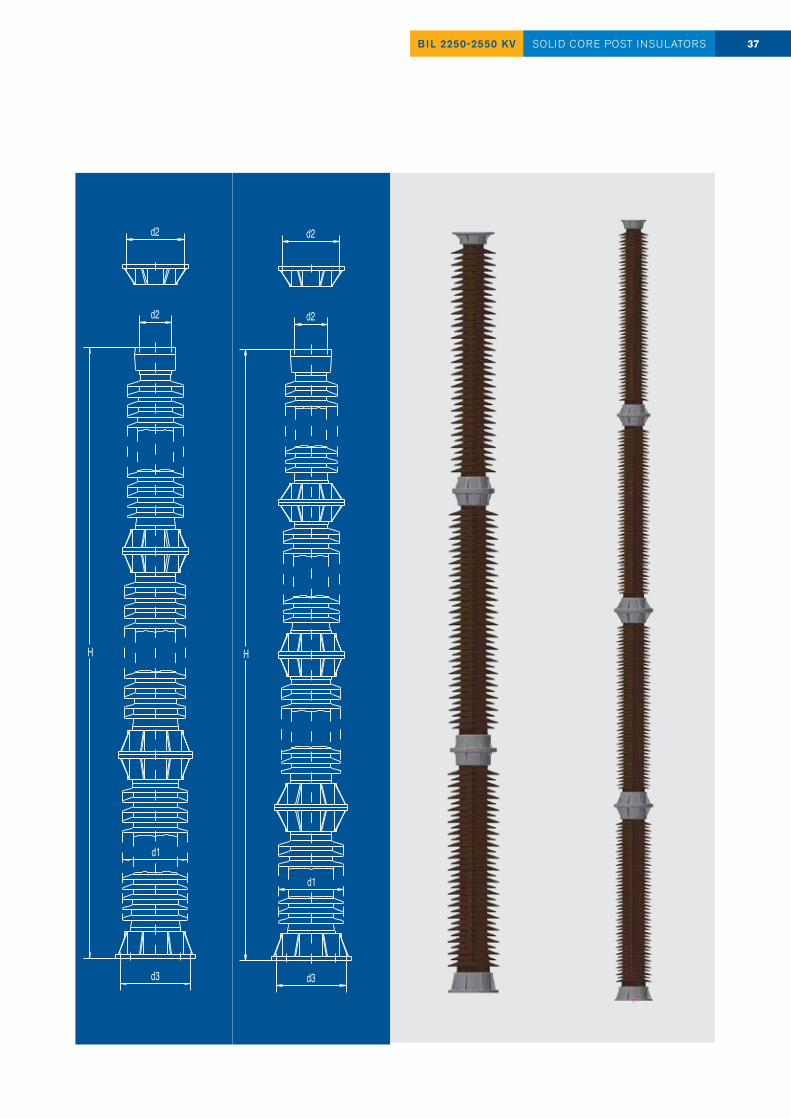
37BIL 2250-2550 KV SOLID CORE POST INSULATORS
Bina Test Station1200 kV Porcelain Station Post Insulators
38 REFERENCESOLID CORE POST INSULATORS
— Bina Test Station is an ultra-high voltage 1200 kV AC testing facility, located in Madhya Pradesh, India. It is one of a kind project - it is the first 1200 kV station in the world!
— Built in 2013, the aim of Bina Test Station is to address increasing electricity demand in India, following rapid demographic growth and economic development.
— After three years in 2016, Bina Test Station has been operationalized, becoming part of Indian power sector, carrying capacity five times to six time more than the 400 kV stations.
— Especially for Bina Test Station, PPC Insulators developed, produced and delivered several dozen of 1200 kV Bus Post Insulators and 1200 kV Operating rod Insulators.

www.ppcinsulators.com
PPC
201
8
PPC Austria Holding GmbHPlankengasse 7 1010 [email protected]
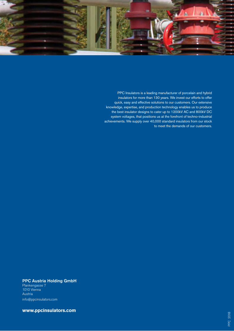
PPC Insulators is a leading manufacturer of porcelain and hybrid insulators for more than 130 years. We invest our efforts to offer
quick, easy and effective solutions to our customers. Our extensive knowledge, expertise, and production technology enables us to produce
the best insulator designs to cater up to 1200kV AC and 800kV DC system voltages, that positions us at the forefront of techno-industrial
achievements. We supply over 40,000 standard insulators from our stock to meet the demands of our customers.
Top Related