


Languages
Pages
Legal


This document is downloaded from DR‑NTU (https://dr.ntu.edu.sg)Nanyang Technological University, Singapore.
Power quality and low voltage ride‑throughcapability of induction generator‑based windpower generating system
Wei, Feng
2014
Wang, F. (2014). Power quality and low voltage ride‑through capability of inductiongenerator‑based wind power generating system. Doctoral thesis, Nanyang TechnologicalUniversity, Singapore.
https://hdl.handle.net/10356/61786
https://doi.org/10.32657/10356/61786
Downloaded on 13 Mar 2022 06:34:28 SGT

WE
I FE
NG
POWER QUALITY AND LOW VOLTAGE RIDE-THROUGH
CAPABILITY OF INDUCTION GENERATOR-BASED WIND
POWER GENERATING SYSTEM
WEI FENG
School of Electrical and Electronic Engineering
A thesis submitted to the Nanyang Technological University
in fulfillment of the requirement for the degree of Doctor of
Philosophy
2014

I
Acknowledgement
First and foremost, I would like to express my deepest gratitude to my supervisor, Prof. D.
Mahinda Vilathgamuwa for his invaluable encouragement, guidance, and directions
throughout my research work.
I am deeply grateful to Prof. Choi San Shing for his immeasurable contributions to my
research work. He kept providing invaluable guidance and support for my PhD degree.
I would like to express special thanks to my co-supervisor, Dr. Sridhar Idapalapati for his
knowledge sharing, guardians and support.
I greatly appreciate Power Division, School of EEE, Nanyang Technological University
for providing me the financial support in the form of research scholarship.
I greatly appreciate Mr. Teo Tiong Seng, Ms. Tan-Goh Jie Jiuan and Ms. Lee-Loh Chin
Khim for providing me so much technical support in Power Electronics Research
Laboratory throughout my research project.
Last but not the least; I would also like to use this opportunity to thank my parents and
friends for their full support and encouragement throughout my research work.
II
Summary
Wind energy has become one of the most important clean energy sources all over the
world. As compared to fixed speed based wind power generators, the variable speed
generators obtain a much higher efficiency. Among the variable speed generators,
permanent magnet synchronous generator (PMSG) is one of the commonly used wind
power generator but it requires a fully rated back-to-back converter connected to the
grid. The doubly-fed induction generator (DFIG) usually obtains the advantages from
economic point of view because the converters are equalized to handle 20-30% of the
rated power. As a result, DFIG has become one of the most widely used wind power
generator nowadays.
However, smaller power rating of the converters also means that the DFIG system
has a smaller tolerance to voltage disturbances. When an external fault occurs, the DFIG
is required to keep connected to the grid and generate reactive power. Thus, low voltage
ride through (LVRT) capability for DFIG is required. However, most of the LVRT
methods either loose control of the generator or significantly increase the cost of the
DFIG system. Mode switch method is proposed in order to improve the LVRT
performance of DFIG. The mode switch DFIG (MSDFIG) switches from the normal
operation expand (DF mode) to induction generator mode (IG mode) while a grid fault
is detected. In IG mode, the stator side is isolated from the grid and in that case, the
transient large current caused by the sudden grid voltage drop can be avoided.
Meanwhile, the rotor-side is kept connected to the grid through a back-to-back
converter by which the generator is still under control and reactive power could be
delivered to the grid. In order to achieve a smooth mode switching, the transient
phenomenon of the generator switches from DF mode to IG mode is analyzed and a
stator-side crowbar is proposed in order to contain the transient current. The
III
resynchronization control of the generator switches from IG mode back to DF mode
when the grid voltage is recovered is also developed. Analysis shows that the proposed
MSDFIG can smoothly ride through the complete low-voltage and voltage recovery
stages. Effectiveness of the scheme is demonstrated through simulation and experiment
studies.
The second contribution of this thesis is the harmonic and unbalanced problems
analysis and elimination for DFIG. In the stand-alone DFIG system, harmonics and
unbalanced components would appear in the voltage at PCC due to nonlinear and
unbalanced loads. The distorted voltage would not only reduce the power quality at the
PCC, but also be harmful for the generator. On the other hand, while the DFIG is
connected in the large grid, the stator current of the generator would be distorted by the
nonlinear or unbalanced loads in the grid. In order to improve the power quality and
avoid harmful effects on the generator, harmonic and unbalanced components should be
eliminated in stand-alone and grid connected DFIGs. Active power filter (APF) is one
of the most commonly used method for harmonic elimination but it increases the cost of
the DFIG system and also needs an individual controller for the APF. Thus, the
compensation control from the rotor-side converter is encouraged recently. The PI
controller, PI-resonant (PIR) controller and PI based repetitive controller (PIRC) for
harmonic and unbalanced components elimination are analyzed. The effectiveness of
PIRC is discussed in great detail and approved by simulation and experimental results.
Unlike conventional power systems, nowadays some of the microgrids adopt DC
distribution because of the availability of increasing number of DC output type sources
such as photovoltaics and fuel cell and also loads such as laptops, computers, LED,
lightening etc. In the conventional connection between the DFIG and DC microgrid
(DCMG) requires a fully rated converter to transfer the AC power generated from the

IV
generator into the DCMG. In that case, the cost of DFIG would significantly increase
and lose its benefits from economic point of view. A new scheme of DFIG is proposed
in which the stator windings are connected to the DCMG through a three phase diode
rectifier and the rotor windings are still connected to a rotor-side converter. Compared
to the conventional scheme, the proposed configuration of DFIG saves the fully rated
converter. But the stator-side rectifier would introduce distorted stator voltages which
are uncontrollable and as a result, harmonic components would appear in the stator
current. The current injected into the DCMG would also be distorted. In order to
eliminate the harmonics in the stator current, PIRC is applied in the controller of rotor-
side converter. For the DC current, the harmonic components are proposed to be
eliminated by a harmonic compensator which is controlled by PIRC. Simulation and
experimental results verify that the PIRC could effectively reduce the harmonics in both
the stator currents and DC current. Meanwhile, in order to improve the efficiency of the
system, the DFIG is controlled by maximum power point tracking (MPPT) and a battery
energy storage system (BESS) is proposed to smooth the power flow and better load
sharing under droop control.

V
Table of Content
Acknowledgement ......................................................................................... I
Table of Content ........................................................................................... V
List of Figures ............................................................................................ VII
List of Tables ............................................................................................ XIII
List of Abbreviations .................................................................................. IX
Chapter 1. Introduction ............................................................................. 1
1.1 Introduction of low voltage ride-through (LVRT) for DFIGs ..................... 3
1.2 Introduction of distorted and unbalanced stator voltage compensation of
stand-alone DFIG ........................................................................................................ 4
1.3 Introduction of research on DC-microgrid connected with DFIGs ............ 5
1.4 Main contribution of the thesis ....................................................................... 7
1.5 Organization of the thesis .............................................................................. 10
Chapter 2. Literature Review .................................................................. 12
2.1 Literature review on LVRT of DFIG ........................................................... 12
2.1.1 Review on crowbar protection .................................................................. 12

VI
2.1.2 Review on ESS protection ......................................................................... 15
2.1.3 Review on injection voltage protection .................................................... 16
2.1.4 Review on injection voltage protection Review on on-load tap changer
protection 19
2.1.5 Review on decoupled-DFIG ..................................................................... 21
2.2 Literature review on harmonic control of DFIGs ....................................... 23
2.2.1 Introduction .............................................................................................. 23
2.2.2 Active power filter for harmonic elimination ........................................... 25
2.2.3 PI controller for harmonic elimination .................................................... 27
2.2.4 PIR controller for harmonic elimination .................................................. 28
2.2.5 PIRC controller for harmonic elimination ............................................... 35
2.3 Literature review on DC-microgrids ........................................................... 38
2.3.1 DCMG voltage controlled by GC ............................................................. 40
2.3.2 DCMG voltage controlled by a large source ........................................... 42
2.3.3 DCMG voltage controlled by distributed source ..................................... 43
2.3.4 DCMG-connected DFIG with a fully rated converter.............................. 45
2.3.5 DCMG-connected DFIG with a stator-side converter ............................. 46

VII
Chapter 3. Design of Mode Switching Scheme for Low Voltage Ride
Though of DFIG .......................................................................................... 48
3.1 DF and IG modes: basic circuit models ....................................................... 49
3.2 Analysis of transient current ........................................................................ 52
3.2.1 DF to IG Mode Switch .............................................................................. 52
3.2.2 Technique to Limit the Transient Current ................................................ 53
3.3 Controllers design .......................................................................................... 54
3.3.1 Controller for the GSC ............................................................................. 55
3.3.2 Controller for the RSC .............................................................................. 55
3.4 Control of crowbar resistance ...................................................................... 61
3.4.1 Transient Currents Limitation .................................................................. 62
3.4.2 Control Strategy of Crowbar Resistance .................................................. 63
3.5 Simulation and experimental verification of MSDFIG for LVRT ............ 65
3.5.1 Simulation results ..................................................................................... 65
3.5.2 Experimental verification ......................................................................... 68
3.6 Conclusion ...................................................................................................... 71
Chapter 4. Mitigation of Unbalanced and Distorted Stator Voltage of
Stand-alone DFIGs Using Repetitive Control .......................................... 72

VIII
4.1 Introduction .................................................................................................... 72
4.2 Modeling and Control of Stand-alone DFIG ............................................... 75
4.2.1 Modeling of DFIG .................................................................................... 75
4.2.2 Control of the Fundamental Component .................................................. 77
4.3 Co-ordinated control method development ................................................. 78
4.3.1 Basic conception of RC ............................................................................ 78
4.3.2 PIRC for RSC ........................................................................................... 78
4.4 Design of PIRC ............................................................................................... 81
4.4.1 Stability Analysis ...................................................................................... 81
4.4.2 Steady-State Analysis ................................................................................ 84
4.4.3 A General Approach to Design the PIRC ................................................. 85
4.5 Simulation results .......................................................................................... 87
4.5.1 With non-linear load ................................................................................. 87
4.5.2 With unbalanced load ............................................................................... 89
4.6 Experimental results ...................................................................................... 90
4.6.1 With non-linear load ................................................................................. 91
4.6.2 With unbalanced load ............................................................................... 92
4.6.3 With combined non-linear and unbalanced loads .................................... 94

IX
4.7 Conclusion ...................................................................................................... 94
Chapter 5. Power Quality Improvement of DC-microgrid with DFIG
Based Wind Power Generation .................................................................. 96
5.1 Introduction .................................................................................................... 97
5.2 DCMG with distributed generators and loads ............................................ 99
5.3 Mitigation of Harmonics of stator current ................................................ 102
5.3.1 Modeling of DFIG .................................................................................. 102
5.3.2 Harmonic Problem of DFIG .................................................................. 103
5.3.3 Harmonic Elimination Control Scheme ................................................. 105
5.3.4 The PIRC System Analysis ...................................................................... 108
5.4 Harmonic elimination of the stator power ................................................ 110
5.5 Voltage control of DCMG ........................................................................... 113
5.5.1 Voltage regulation by control of BESS ................................................... 113
5.5.2 Control of RSC ....................................................................................... 115
5.5.3 Control mode selection ........................................................................... 116
5.6 Case study ..................................................................................................... 117
5.6.1 Harmonic elimination of stator current ................................................. 118
5.6.2 Harmonic elimination for the output power of DFIG ............................ 123

X
5.6.3 Load sharing under droop control with a step change load .................. 124
5.7 Conclusion .................................................................................................... 127
Chapter 6. Conclusion ............................................................................ 129
6.1 Conclusion ..................................................................................................... 129
6.2 Recommendations for Future Research ......................................................... 131
Appendix 3-A ............................................................................................. 134
Appendix 3-B ............................................................................................. 135
Appendix 4-A ............................................................................................. 137
REFERENCES .......................................................................................... 138
Publications ................................................................................................ 151

VII
List of Figures
Figure 1-1 Typical configuration of (a) stand-alone DFIG, (b) grid connected DFIG ............. 2
Figure 2-1 Configuration of a DFIG wind turbine system with a crowbar system ................ 13
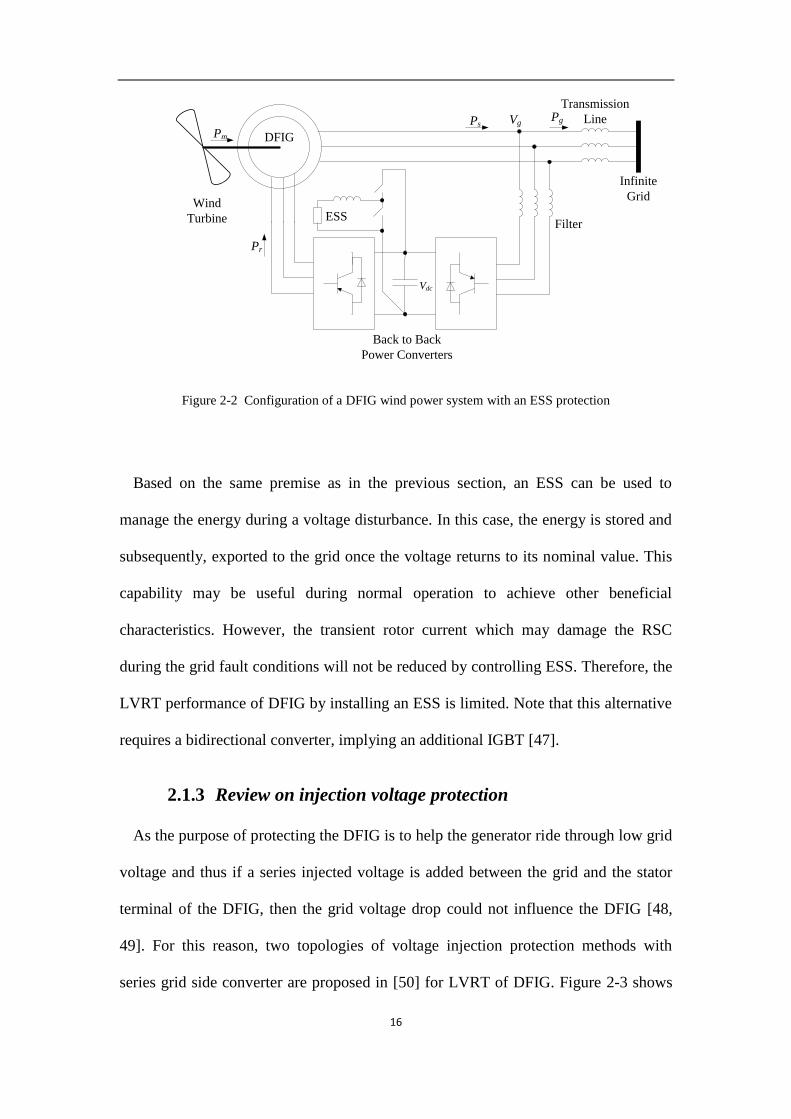
Figure 2-2 Configuration of a DFIG wind power system with an ESS protection ................. 16
Figure 2-3 Configuration of a DFIG wind power system with a Y point connected series
compensation ........................................................................................................................... 17
Figure 2-4 Configuration of a DFIG wind power system with a series connected transformer
compensation ........................................................................................................................... 17
Figure 2-5 Configuration of a DFIG with an on load tap changer transformer ....................... 20
Figure 2-6 Decoupled-DFIG applied for LVRT...................................................................... 22
Figure 2-7 The vector diagram respecting the relationship between different reference frames
................................................................................................................................................. 24
Figure 2-8 PCC voltage harmonic elimination of stand-alone DFIG using APF .................... 26
Figure 2-9 Stator current harmonic elimination of grid-connected DFIG using APF ............. 26
Figure 2-10 Control scheme of the grid connected DFIG for stator current harmonic
elimination using PI controller ................................................................................................ 28
Figure 2-11 Control scheme of stand-alone DFIG using PIR in synchronous frame .............. 29
Figure 2-12 Control scheme of stand-alone DFIG using PIR in stationary frame .................. 30
Figure 2-13 Block diagram of stator current controller ........................................................... 31
Figure 2-14 Improved control scheme of the grid-connected DFIG using resonant loop ....... 32

VIII
Figure 2-15 Improved control scheme of the stand-alone DFIG using resonant loop ............ 33
Figure 2-16 Improved control scheme of the DFIG using PIR for unbalanced component
elimination ............................................................................................................................... 34
Figure 2-17 (a) Generator of periodic signal, (b) RC loop ...................................................... 36
Figure 2-18 Three-phase grid-connected inverter with hybrid PIRC control scheme in
synchronous frame .................................................................................................................. 37
Figure 2-19 Three-phase grid-connected inverter with hybrid PIRC control scheme in
stationary frame ....................................................................................................................... 38
Figure 2-20 DCMG with the voltage controlled by GC .......................................................... 41
Figure 2-21 DCMG with its voltage controlled by CSG ......................................................... 42
Figure 2-22 Configuration of a DCMG-connected DFIG with individual voltage control ..... 43
Figure 2-23 Configuration of a DCMG- connected DFIG with a fully rated GSC ................. 46
Figure 2-24 Configuration of a DCMG-connected DFIG with a stator-side converter (S-SC)47
Figure 3-1 Schematic of a grid-connected DFIG .................................................................... 49
Figure 3-2 DFIG under (a) DF mode and (b) IG mode of connection .................................... 50
Figure 3-3 Equivalent circuit of the DFIG ............................................................................. 51
Figure 3-4 DFIG with a stator-side crowbar (SSC) ................................................................. 54
Figure 3-5 Control schematic for rotor-side converter ............................................................ 56
Figure 3-6 Equivalent circuit of the DFIG in the IG mode ..................................................... 59

IX
Figure 3-7 Switching sequences of S1, S2 and S3. (1 stands for switch on and 0 stands for
switch off)................................................................................................................................ 61
Figure 3-8 Transient rotor current under a range of (a) initial active power Pd at pf = 1, (b)
power factor for apparent power S = 1 p.u., (c) stator resistance for S = 1 p.u. and pf = 0.9
(leading) and (d) Crowbar resistance control for various initial Pd at pf = 0.9 (leading) ........ 62
Figure 3-9 Control strategy of crowbar: S=1.0 and pf=0.9 leading ......................................... 64
Figure 3-10 Profiles of (a) grid voltage; (b) rotor currents under DFIG and MSDFIG; (c)
stator voltage waveform of MSDFIG and expanded plot; (d) active output power of MSDFIG;
(e) reactive output power of MSDFIG; (f) DC-link voltage of MSDFIG (all plots in p.u. value)
................................................................................................................................................. 65
Figure 3-11 Comparison of (a) grid voltage, (b) stator current resulting from conventional
DFIG and proposed MSDFIG schemes ................................................................................... 67
Figure 3-12 (a) Schematic diagram of the experimental setup, (b) Photograph of the
experimental setup ................................................................................................................... 69
Figure 3-13 DFIG under three-phase 0.8 p.u. voltage sag: without mode switching .............. 70
Figure 3-14 MSDFIG under three-phase 0.8 p.u. voltage sag: (a) Res=1.5 p.u.; (b) Res=0.25
p.u. ........................................................................................................................................... 70
Figure 4-1 Typical configuration of stand-alone DFIG connected to nonlinear and unbalanced
loads ........................................................................................................................................ 75
Figure 4-2 Equivalent circuit of the DFIG in stator reference frame ...................................... 75
Figure 4-3 Proposed RSC controller for stand-alone DFIG connected to unbalanced and non-
linear loads .............................................................................................................................. 79

X
Figure 4-4 Block diagram of stator voltage controller ............................................................ 80
Figure 4-5 Stability condition for krc determination ................................................................ 83
Figure 4-6 Frequency response of (a) RC with variable krc at Q=1 and (b) RC with variable Q
at krc=0.2, (c) G1, (d) G2 and (e) G3 with and without RC loop ............................................... 86
Figure 4-7 Simulation results: (a) rotor current, (b) magnitude of 5th and 7
th harmonic
components of stator voltage (c) phase “a” stator voltage and (d) phase “a” stator current
under nonlinear load condition under conventional control and that under PIRC (All
quantities are in p.u.), (e) FFT analysis of stator voltage and (f) rotor current. ...................... 88
Figure 4-8 Simulation results: (a) positive phase sequence component magnitude of vs, (b)
negative phase sequence component magnitude of vs, (c) three phase stator voltage and (d)
phase “a” rotor current under unbalanced load condition under conventional control and that
under PIRC (All quantities are in p.u.), (e) FFT analysis of rotor current. ............................. 89
Figure 4-9 Experimental setup of a 1.5-kW stand-alone DFIG............................................... 91
Figure 4-10 Rotor current and stator voltage with (a) conventional controller and (b) PIRC
with a non-linear load connected at the PCC .......................................................................... 92
Figure 4-11 Rotor current and stator voltage under unbalanced load conditions with a heavier
load connected to one phase: under (a) conventional controller and (b) PIRC; with a lighter
load connected to one phase: under (c) conventional controller and (d) PIRC. ...................... 93
Figure 4-12 Rotor current and stator voltage with (a) conventional controller and (b) PIRC
with combined non-linear and unbalanced loads connected at the PCC ................................. 94
Figure 5-1 DC microgrid ......................................................................................................... 99
Figure 5-2 Distributed DFIG with power buffer and local load ............................................ 100

XI
Figure 5-3 SSR of the DFIG .................................................................................................. 103
Figure 5-4 (a) Diode conduction sequence, (b) waveform of stator phase to phase voltage, (c)
waveform of stator phase voltage .......................................................................................... 104
Figure 5-5 Equivalent circuit of the DFIG ........................................................................... 105
Figure 5-6 Improved control scheme of the DFIG with RC loops ........................................ 106
Figure 5-7 Block diagram of stator current controller ........................................................... 106
Figure 5-8 Frequency response of RC loop ........................................................................... 109
Figure 5-9 Frequency response of (a) Gi1, (b) Gi2 and (c) Gi3 with and without PIRC ......... 109
Figure 5-10 Control of SC ..................................................................................................... 111
Figure 5-11 Control of BESS of xth node ............................................................................. 114
Figure 5-12 Voltage maintenance by control of RSC ........................................................... 116
Figure 5-13 Small DCMG for case study .............................................................................. 118
Figure 5-14 Waveforms of (a) stator voltage, (b) stator current, (c) rotor current, (d) FFT
analysis of stator current at ωr=0.8 p.u. ................................................................................. 119
Figure 5-15 Waveforms of (a) stator voltage, (b) stator current, (c) rotor current, (d) FFT
analysis of stator current at ωr=1.0 p.u. ................................................................................. 119
Figure 5-16 Waveforms of (a) stator voltage, (b) stator current, (c) rotor current, (d) FFT
analysis of stator current ωr=1.2 p.u. ..................................................................................... 119
Figure 5-17 Experimental setup ............................................................................................ 120
Figure 5-18 Experimental waveform of the stator voltage .................................................... 121

XII
Figure 5-19 Experimental waveform of stator and rotor currents (a) without compensation, (b)
with compensation at ωr=1.0 p.u. .......................................................................................... 122
Figure 5-20 Experimental waveform of stator and rotor currents (a) without compensation, (b)
with compensation at ωr=1.2 p.u ........................................................................................... 122
Figure 5-21 Experimental waveform of stator and rotor currents (a) without compensation, (b)
with compensation at ωr=0.8 p.u. .......................................................................................... 122
Figure 5-22 Harmonic elimination of is-DC1 ........................................................................... 124
Figure 5-23 Local DC voltage and source current at each node with step change load ........ 125
Figure 5-24 Local DC voltage and source current at each node when S1 is open ................. 126

XIII
List of Tables
Table 3-1 Parametric Values of a 1.5-MW, 60-Hz, 380-V 6-Pole Wound Rotor Induction
Machine ................................................................................................................................... 62
Table 3-2 Parametric Values of a 1.5-kW, 50-Hz, 220-V 4-Pole DFIG for Experiment ........ 68
Table 4-1 Parameters of DFIG for simulation and experimental test ...................................... 85
Table 5-1 Mode selection of control of BESS and RSC ....................................................... 117
Table 5-2 Parameters of the system ....................................................................................... 118

IX
List of Abbreviations
BESS
BPF
CB
CSG
DC
DCMG
DF
DFIG
DG
GSC
IG
IMP
LSC
LVRT
MG
MPPT
MSDFIG
PCC
PI
PIR
PIRC
PMSG
RC
RSC
SC
SOC
SSC
SSR
Battery Energy Storage System
Band-Pass Filter
Circuit Breaker
Converter of Synchronous Generator
Direct Current
DC-Microgrid
Doubly-fed
Doubly-fed Induction Generator
Distributed generator
Grid-side Converter
Induction Generator
Internal Mode Principle
Load-side Converter
Low Voltage Ride Through
Microgrid
Maximum Power Point Tracking
Mode Switching Doubly-fed Induction Generator
Point-of-Common Coupling
Proportional-Integral
PI control schemes with Resonant loops
Repetitive PI Control
Permanent Magnetic Synchronous Generator
Repetitive Control
Rotor-side Converter
Super Capacitor
State of Charge
Stator-Side Crowbar
Stator-Side Rectifier

1
Chapter 1. Introduction
The research efforts on the renewable and clean energy generation systems are
receiving increasing attention globally. As one of the most attractive renewable
energy sources, wind energy is well known for its low cost, high energy density and
low pollution operational characteristics. It is expected that the penetration of wind
power around the world will reach 12% by 2020 and the wind power generation will
continually contribute to the global energy production in the future [1].
Constant speed and variable speed wind power generators are two types of main
generators used in wind farms. For effective harnessing of wind power, variable speed
constant frequency generators (VSCFGs) are always favored. Among variable speed
constant frequency generators, permanent magnet synchronous generator (PMSG) is
widely used in small wind farms but it requires a fully rated converter with a high cost.
As one of the VSCFGs, DFIG is used extensively because of the following
advantages.
Low cost. Because the power converter of the DFIG only handles 20% to 30%
of the total power, therefore DFIGs are more attractive from an economical point of
view.
High efficiency. Because of the power rating of the converters of DFIG is
much lower than that of other generators, the power loss of the converter is much
smaller and the power efficiency is higher.
Larger power capacity. Because of the DFIG is self-excited generator, the
power capacity can be much higher than that of PMSG with the same cost.

2
DFIG is controlled by a back-to-back converter. There are two modes of connection
of DFIGs, grid-connection mode and stand-alone mode. The stator side is connected
to the grid or loads in grid-connected or stand-alone mode, respectively. The rotor
side is connected to a back to back converter. Figure 1-1 shows the fundamental
schemes of grid-connected and stand-alone DFIGs. In the stand-alone DFIG, the load-
side converter (LSC) is controlled to maintain the DC link voltage and the rotor-side
converter (RSC) for stator voltage and reactive power control to supply the loads. In
the grid-connected DFIG, the GSC is controlled for the regulation of DC link voltage
and RSC is controlled for MPPT and stator-side reactive power support.
Vdc
PCC
RSC
controller
LSC
controller
svDFIG
Gear
Pitch
r RSC LSC
ri
si
LoadsQ
*sv
*r
*dcV
(a)
Vdc
PCC
RSC
controller
GSC
controller
svDFIG
Gear
Pitch
r RSC GSC
ri
si
Grid
sQ
*r
*sQ
*dcV
(b)
Figure 1-1 Typical configuration of (a) stand-alone DFIG, (b) grid connected DFIG

3
1.1 Introduction of low voltage ride-through (LVRT)
for DFIGs
As aforementioned, DFIGs are more attractive from an economical point of view
and extensively used because the power converter of the DFIG only handle 20% to 30%
of the total power. But unfortunately, the smaller power rating of the converters also
means that the DFIG system has a smaller tolerance to voltage disturbances. In grid-
connected mode, when an external fault occurs, the abrupt stator voltage sag would
produce a dc component in the stator flux which appears as an oscillatory
electromagnetic field in the rotor circuit. Severe voltage sag could lead to large
outrush current on both the stator and rotor circuits, consequently the current can
overload the converters. On the other hand, grid codes require the generator to remain
connected to the grid during the fault [2]. So far, many LVRT approaches have been
proposed in the literatures [3-7].
All the proposed LVRT approaches can be divided into two types. First one is the
modification of the software, like improving the control scheme of the DFIG to
enhance the LVRT performance [8, 9]. And the second one is changing the
configuration of DFIG, like adding a series connected compensation device at the
stator-side of DFIG to compensate the voltage during grid fault conditions [7, 10, 11].
A MSDFIG scheme is proposed for the purpose of achieving low voltage ride-
through for wind turbines [12]. The MSDFIG operates as a DFIG under normal
condition but upon the detection of a low-voltage incident, the generator is to
smoothly transfer to IG mode through the switching in of a set of stator-side crowbar.
A new strategy on the control of the crowbar resistance is proposed. The MSDFIG
automatically reverts back to the DFIG mode when network voltage recovers.

4
Analysis shows that the proposed MSDFIG scheme can ride through the complete
low-voltage and voltage recovery stages. Effectiveness of the scheme is demonstrated
through simulation and experiment studies.
1.2 Introduction of distorted and unbalanced stator
voltage compensation of stand-alone DFIG
When the DFIG is operated in the stand-alone mode, the voltage at the PCC is
maintained by controlling the RSC of DFIG [9]. The stand-alone generator system
will have to operate with nonlinear and unbalanced loads connected to it. Such loads
draw distorted or unbalanced currents which will result in distorted and unbalanced
voltages at the stator terminals of the generators. The negative phase sequence
component of the unbalanced stator voltage would induce electromagnetic torque
pulsations and excessive heat in the generators. Efficiency of the generators is
degraded and the performance of other loads will be affected. Therefore, it is desirable
to eliminate the negative phase sequence and harmonic components of the stator
voltage in order to overcome such deficiencies.
In [13], the harmonic load current is compensated by using a traditional PI
controller designed based on the synchronous reference frame. However, the PI
controller has small gains at the harmonic frequencies. Therefore, the effectiveness of
this method is limited. Alleviation of similar voltage quality problems using PI
controllers based on harmonic reference frames has been proposed in [14]. In these
methods, the stator voltage is transformed into the synchronous reference frame and
the negative phase sequence [14] and harmonic [15] components respectively are
extracted using band-pass filters (BPFs) and then transformed into their corresponding

5
reference frames. Unfortunately the methods require large amount of calculations.
Alternatively, PIR control has been proposed in [6, 16, 17]. Two resonant loops are
required for each of the 6 1 ( 1,2...)n n order harmonic components. The
unbalanced component is also eliminated along with the 5th
and 7th
harmonic
components [18] using the PIR controllers, but the elimination of the unbalance
component requires another resonant loop. Consequently, the main drawback of PIR
controller is that each resonant loop can only damp the harmonic component
corresponding to its resonant frequency.
An alternative approach for harmonic elimination is to use RC method [19-23]. The
RC presents large gain at integer multiples of the fundamental frequency and is well
known for its effectiveness in controlling harmonics [20]. It has been proposed in [16]
to reduce the current harmonics of a DC/AC inverter using a hybrid scheme which
combines PI and RC techniques. However, it has yet to be extended for the case of
stand-alone DFIGs. In Chapter 3, the proposed PIRC scheme is to eliminate the
unbalance and harmonic components of the stator voltage of a stand-alone DFIG. In
synchronous reference frame, the fundamental components of the stator voltage are
regulated by PI controllers while the unbalance and harmonic components are
eliminated through the application of RC technique.
1.3 Introduction of research on DC-microgrid
connected with DFIGs
DG systems like wind turbines, photovoltaics and fuel cells are increasingly
installed in utility grids presently [24-29] but it introduces problems like unstable
voltage, current harmonics and frequency vibration. As a result, microgrids (MGs) are

6
researched extensively in order to solve problems like voltage variations and
protection issues when large amount of DGs are connected to the grid. It is envisaged
that DC microgrids (DCMGs) will be used immensely in future because of significant
amount of DC loads and increasing number of DC output type sources such as
photovoltaics, fuel cells and batteries are installed into the grid [30, 31].
Doubly-fed induction generator is one of the most commonly used wind power
generators over the world but it is not so widely used in DC-microgrids. The
advantages of DFIGs are summarized in Section 1.1. But when the DFIG is connected
to a DCMG, a converter with full power rating is required in the conventional
configuration to transfer AC power generated by DFIG to DCMG. Comparing with
PMSG that connected in DCMG, the advantages of DFIG will be disappeared. To
overcome this shortcoming, it is proposed in this study that a stator-side rectifier (SSR)
be installed between the stator and the DCMG so that the cost of the DFIG system can
be kept to a low value. With this configuration, harmonics appear on both the stator
currents and stator power in the proposed DFIG configuration because of SSR. It is
proposed in this research that the stator current harmonics are compensated using
control of RSC and an additional supercapacitor (SC) interfaced with DCMG is used
for stator power harmonic elimination. Compared with PI [32] and PI-R control [33,
34], repetitive control (RC) technique that requires a low calculation burden is
proposed in the control of SC to eliminate the harmonics in the DC side of SSR.
The efficiency of the generator is another concern when it is connected to the
DCMG. If the DFIG is controlled to maintain the voltage in a small system or in
stand-alone conditions, the output power of the DFIG will be determined by the loads
and the maximum power point tracking (MPPT) cannot be done anymore. As a result,

7
the efficiency of the DFIG will be decreased. It is proposed in this paper that a battery
energy storage system (BESS) is interfaced to the DCMG for the purpose of power
buffering. In such a case, the grid voltage can be maintained with the control of BESS
and the DFIG would be able to perform MPPT in order to achieve a greater efficiency.
BESS has a limited capacity so that if the load sharing is unequal, the BESS can be
easily fully charged or discharged in some nodes with lighter or heavier loads
respectively. In order to prevent this situation, an improved droop control is applied in
the control of BESS for the purpose of equitable load sharing and stable DC voltage.
Even though an improved droop control has been discussed in [35], it needs further
modifications when a DFIG is installed in the DCMG. In order to improve the
reliability of the system, when the BESS is fully charged or out of service due to fault
conditions, the DFIG will be switched to a control mode where the local DC voltage
is regulated to achieve DC voltage droop control. With this proposed control, the
system can be kept stable even the BESS is out of service.
1.4 Main contribution of the thesis
The main contribution of this research work could be summarized as follows.
First of all, in order to improve the LVRT performance of DFIG, an improved
MSDFIG is proposed in Chapter 3. Two modes of DFIG connection are discussed. In
MSDFIG, the generator is in normal operation like conventional DFIG and works in
DF mode. Once a grid voltage drop is detected, the generator will be converted to IG
mode in which the stator windings are isolated from the large grid. Thus, the voltage
drop on the large grid will not affect the generator.

8
In the proposed MSDFIG, the smooth mode switching is achieved by the control of
SSC. After the DFIG is switched to IG mode, it will continue generating real power
and at the same time, reactive power is also regulated by control of RSC to supply the
grid during grid fault condition.
The DFIG will be switched back to DF mode after the grid voltage is recovered. In
order to achieve a smooth mode switch, the control of DFIG will be switched to
synchronous mode to control the stator voltage. Once the stator voltage gains the
required amplitude, phase and sequence of the grid voltage, the stator can be
connected to the grid and the DFIG will be back to DF mode under normal control.
Thus, the LVRT of DFIG can be achieved smoothly.
The second main contribution of the research work is the harmonic elimination of
DFIG using the RC. Harmonic problems in both stand-alone and grid-connected
DFIG are analyzed.
In stand-alone DFIG, harmonic and unbalanced components may be present in the
stator voltage and current when some non-linear or unbalanced loads are connected at
the PCC. The power quality at the PCC will be significantly depraved by the
harmonics.
While for the grid-connected DFIG, the distorted grid voltage would lead to
harmonic or unbalanced components in the stator current. The harmonic current is
harmful for the DFIG and therefore, harmonics need to be eliminated.
RC technique is applied for the elimination of harmonic and unbalanced
components in stator voltage of stand-alone DFIG and stator current of grid-connected

9
DFIG. Compared with the harmonic control methods introduced in previous
literatures, the advantages of the proposed RC can be summarized as follows:
• Both unbalanced and harmonic components shall be eliminated using the same
proposed controller. Therefore the proposed control scheme imposes much less
computational burden;
• Regardless of the reference frame, the proposed controller can effectively deal
with the periodic signals. This is unlike existing PI or PIR controllers in which the
control systems have to be changed when using different reference frames.
The third contribution of the research work is the proposal of a novel configuration
of DCMG-connected DFIG and the development of corresponding controllers for the
elements in the DCMG.
A generic DCMG can be divided into different nodes and each node can consist of
local sources and local loads. In order to keep the cost of DFIG at a low value, a novel
configuration of DFIG interfaced with DCMG is designed in which the stator is
connected to the DCMG using a SSR. In this configuration, the harmonic problem is
analyzed. For the purpose of stator current harmonic elimination, the PIRC is applied
in the control of RSC. And for the stator power harmonic control, a SC is installed at
the DCMG and PIRC is applied in the control of SC to compensate the harmonics in
the stator power.
Moreover, to achieve high efficiency in the DFIG, the DFIG is controlled for MPPT
and a BESS is installed in each node to maintain the local voltage constant. This
configuration not only improves the power efficiency of the DCMG, but also achieves
a higher reliability of the system. When the BESS is fully charged/discharged or cut

10
off due to faults, the DFIG will switch to another control model for the purpose of
local voltage control. Furthermore, in order to achieve a stable DCMG voltage and
equal load sharing, an improved droop control is applied in the DCMG voltage
control.
1.5 Organization of the thesis
The organization of the thesis can be summarized as follows.
In Section 2.1, a brief literature review on LVRT of DFIG is given. The benefits
and disadvantages of crowbar, ESS, injection voltage, on-load tap changer and
decoupled protection methods are discussed in Sections 2.1.1, 2.1.2, 2.1.3, 2.1.4 and
2.1.5, respectively.
In Section 2.2, the literature review on harmonic control of DFIG is given. The
method of installing an active power filter is analyzed in Section 2.2.2. The
corresponding reference frames are introduced in Section 2.2.3 and 2.2.4 for harmonic
elimination using PI and PIR type controllers, respectively. Finally, the PIRC
technique is introduced in Section 2.2.5.
The literature review on DCMG is given in Section 2.3. The DCMG voltage
controlled by a grid converter (GC) and a large synchronous generator is discussed in
Section 2.3.1 and 2.3.2, respectively. A distributed voltage control by distributed
sources is described in Section 2.3.3. The configuration of a DCMG-connected DFIG
with a fully rated GSC is introduced in Section 2.3.4 and that with a stator-side
converter (S-SC) is discussed in Section 2.3.5.

11
Based on the analysis in Section 2.1, an improved MSDFIG is proposed in Chapter
3. The basic concept of DF and IG mode of connection is introduced in Section 3.2
and the transient current analysis is shown in Section 3.3. The controller design for
RSC, GSC and SSC is discussed in Section 3.4. The simulation and experimental
results are given in Section 3.5 to verify that the MSDFIG can improve the LVRT
performance of DFIG significantly.
In Chapter 4, the harmonic elimination of stand-alone DFIG is discussed. The
modeling of stand-alone DFIG is given in Section 4.2 and based on that, the co-
ordinated control method using PIRC is developed in Section 4.3. The system analysis
is performed in Section 4.4 to guarantee the stability and effectiveness. Finally, the
effectiveness of the proposed control has been proved by simulation and experimental
results.
A novel configuration of DCMG-connected DFIG is proposed in Chapter 5. In the
proposed configuration, an SSR is connected between the stator and the grid. The
introduction of DCMG with distributed generators and loads are given in Section 5.2
and the aims of the controller design are discussed. The harmonic problem and the
corresponding harmonic elimination control using PIRC are discussed in Section 5.3.
In Section 5.4, the stator power harmonic elimination is achieved by installing an SC
which is controlled using PIRC. The improved droop control for DCMG voltage and
the reliability improvement by control mode selection are introduced in Section 5.5.
Finally, the effectiveness of stator current harmonic control is verified by simulation
and experimental results. The performance of stator power harmonic control and
DCMG voltage control are illustrated in Section 5.6.

12
Chapter 2. Literature Review
2.1 Literature review on LVRT of DFIG
In this section, a brief literature review on LVRT of DFIGs will be given. The
LVRT techniques such as crowbar, ESS, injection voltage, on-load tap changer and
decoupled protection methods are discussed in detail. However, there are certain
problems still need to be solved. For example, in all aforementioned LVRT
techniques, the DFIG may absorb reactive power from the grid because the stator
winding of DFIG is connected to the grid during fault. Such a scenario can deteriorate
the fault condition. Moreover, when the grid voltage starts to oscillate in fault
conditions, it can give rise to large transient stator and rotor currents if
aforementioned LVRT methods are adopted. In order to overcome such drawbacks,
the MSDFIG is proposed and discussed in Chapter 3.
2.1.1 Review on crowbar protection
The commonly used method for LVRT of DFIG is crowbar protection [36]. The
topology for crowbar protection is shown in Figure 2-1. This topology is widely used
in DFIG manufacturing because of its low cost. As described in [36], the controller of
DFIG could be improved to help the DFIG ride through slight voltage drop or
unbalanced voltage but for deep grid faults or the instances of DFIG working in high
rotor speed conditions during grid faults could lead to large transient rotor currents. In
such cases, the improvement of control strategy is not good enough for DFIG
protection and thus a hardware protection is necessary. Most of the recent research is
focused on this objective and the commonly accepted solution for this problem is to
install a crowbar at the terminal of rotor winding. Many articles in literature have

13
researched on this topology of crowbar circuit recently. There are three aspects of
crowbar circuit that have been researched.
Resistance determination of crowbar protection design
The research on how to determine resistance of crowbar is introduced in [37] and
[38] which insist that the resistance determination is quite important in crowbar
protection system. If the resistance is too small then it is hard to reduce the rotor
transient current rapidly and if it is too large, then the transient voltage that the
converters have to suffer could be too high and as a result, the power electronic
devices could be damaged. In DFIG design, the resistance of the crowbar is somewhat
determined by experience.
Control of crowbar connection
The most commonly used control strategy of crowbar connection is to detect the
rotor current and if it is over current, the crowbar should be connected. In [39], the
rotor current is also detected but a time delay is used in this control strategy for the
purpose of avoiding too frequent connection and mal-operation of the crowbar.
Infinite
GridTransformer
Transmission
LinePsPg
Pr
Pm DFIG
Back to Back
Power Converters
Filter
Wind
Turbine
Vg Vig
Vdc
Crowbar
Figure 2-1 Configuration of a DFIG wind turbine system with a crowbar system
14
Research in [40] proposed a voltage detecting method for crowbar control and if a
voltage drop is detected then the crowbar circuit is connected and is disconnected
after a time delay. Both the rotor current and grid voltage are detected in [3] and the
crowbar should be connected to the rotor windings either when the voltage drop or
current increase is detected.
Control of crowbar disconnection
The crowbar circuit disconnection is more important compared with the connection
because either too early or too late disconnection is harmful for the DFIG system.
This is because after the rotor winding is connected with the crowbar, the DFIG
would work like squirrel type generator which would absorb reactive power from the
grid. When a grid fault occurs, if the generator absorbs reactive power from the grid,
it cannot help the system recover from the fault condition and thus, long term
connection of the crowbar should be avoided in DFIG operation. On the other hand, if
the crowbar circuit is disconnected from the DFIG before the transient rotor current
decreases to a certain value, the control system would connect the crowbar circuit to
the rotor again. Thus, it is not good for the stability of the DFIG system.
Furthermore, after the crowbar circuit is connected, the determination of the
reference value of the rotor current control loop and the design of the PI controller are
very important. In [41], it is pointed out that if the reference value of rotor current is
not given correctly, it could lead to the over current in rotor circuit again and re-
connection of crowbar circuit. Actually, every part of a DFIG crowbar system needs
to work cooperatively under a correct logical controller for successful LVRT. But
unfortunately, no paper in the literature discusses about this subject until now and this
is one of the main further works for LVRT of DFIG.

15
2.1.2 Review on ESS protection
Besides the crowbar protection of the DFIG, an ESS protection could be
considered in LVRT of DFIG which is shown in Figure 2-2. In many cases, the
dynamics of the DC-link voltage are ignored but it is also important to keep the DC
voltage steady [42]. The energy stored in the ESS would change by controlling the
ESS voltage. Therefore, the ESS could be used to absorb the power which could
otherwise damage the converters. Another alternative way similar to ESS protection is
to use a dumping resistance instead of the energy storage device. This circumvents the
problems associated with transfer between the different operating modes. The
drawback of this topology is that the rotor side converter must be sized accordingly.
However, the gains associated with continuously controlling the machine throughout
the fault may outweigh the cost of over-sizing the converters. Furthermore, the
overrating will only be required for the current carrying capability of IGBTs. The
thermal time constant is sufficiently long in order to handle dissipation of the
additional energy. Numerous energy storage devices are researched in wind energy
storage techniques [43-46], such as supercapacitor energy storage and fuel cell storage.
The alternate variable-speed WTG topology is that of the full converter interfaced
machine, typically a synchronous machine with either wound rotor or permanent
magnet. The advantages of this topology lie in the decoupling of the grid dynamics
from those of the machine, achieved by the isolation resulting from the power
electronic converter. For low voltage events, the energy that is produced by the
machine still needs to be managed, particularly for severe, long duration events,
which cannot be absorbed by the DC capacitor. For the DFIG, various alternatives
exist.
16
Infinite
Grid
Transmission
LinePsPg
Pr
Pm DFIG
Back to Back
Power Converters
Filter
Wind
Turbine
Vg
Vdc
ESS
Figure 2-2 Configuration of a DFIG wind power system with an ESS protection
Based on the same premise as in the previous section, an ESS can be used to
manage the energy during a voltage disturbance. In this case, the energy is stored and
subsequently, exported to the grid once the voltage returns to its nominal value. This
capability may be useful during normal operation to achieve other beneficial
characteristics. However, the transient rotor current which may damage the RSC
during the grid fault conditions will not be reduced by controlling ESS. Therefore, the
LVRT performance of DFIG by installing an ESS is limited. Note that this alternative
requires a bidirectional converter, implying an additional IGBT [47].
2.1.3 Review on injection voltage protection
As the purpose of protecting the DFIG is to help the generator ride through low grid
voltage and thus if a series injected voltage is added between the grid and the stator
terminal of the DFIG, then the grid voltage drop could not influence the DFIG [48,
49]. For this reason, two topologies of voltage injection protection methods with
series grid side converter are proposed in [50] for LVRT of DFIG. Figure 2-3 shows

17
the Y point connected series grid side converter topology and the transformer
interfaced series grid side converter topology is shown in Figure 2-4.
Infinite
Grid
Ps
Pr
Pm DFIG
Back to Back
Power ConvertersFilter
Wind
Turbine
Vg
Vdc
Vinj
Figure 2-3 Configuration of a DFIG wind power system with a Y point connected series compensation
Infinite
Grid
Ps
Pr
Pm DFIG
Back to Back
Power Converters Filter
Wind
Turbine
Vg
Vdc
Vinj
Figure 2-4 Configuration of a DFIG wind power system with a series connected transformer
compensation
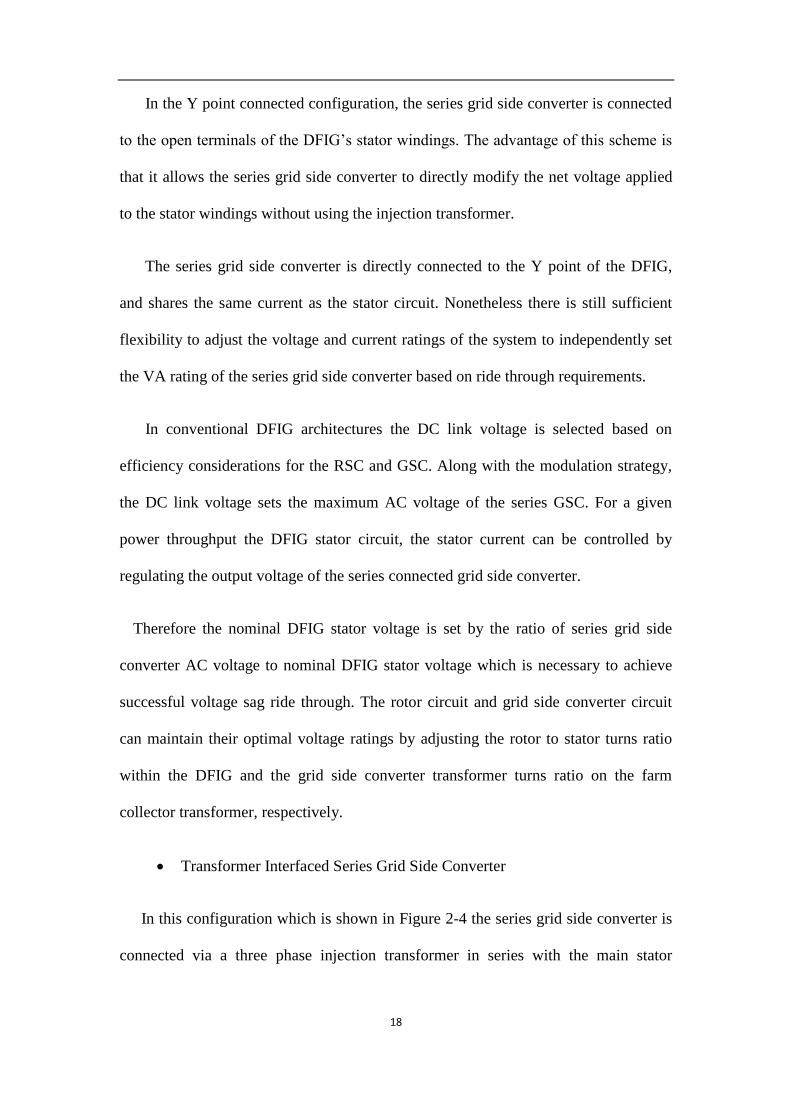
Y Point Connected Series Grid Side Converter
18
In the Y point connected configuration, the series grid side converter is connected
to the open terminals of the DFIG’s stator windings. The advantage of this scheme is
that it allows the series grid side converter to directly modify the net voltage applied
to the stator windings without using the injection transformer.
The series grid side converter is directly connected to the Y point of the DFIG,
and shares the same current as the stator circuit. Nonetheless there is still sufficient
flexibility to adjust the voltage and current ratings of the system to independently set
the VA rating of the series grid side converter based on ride through requirements.
In conventional DFIG architectures the DC link voltage is selected based on
efficiency considerations for the RSC and GSC. Along with the modulation strategy,
the DC link voltage sets the maximum AC voltage of the series GSC. For a given
power throughput the DFIG stator circuit, the stator current can be controlled by
regulating the output voltage of the series connected grid side converter.
Therefore the nominal DFIG stator voltage is set by the ratio of series grid side
converter AC voltage to nominal DFIG stator voltage which is necessary to achieve
successful voltage sag ride through. The rotor circuit and grid side converter circuit
can maintain their optimal voltage ratings by adjusting the rotor to stator turns ratio
within the DFIG and the grid side converter transformer turns ratio on the farm
collector transformer, respectively.
Transformer Interfaced Series Grid Side Converter
In this configuration which is shown in Figure 2-4 the series grid side converter is
connected via a three phase injection transformer in series with the main stator

19
windings of the DFIG. The Y point of the machine is internally tied together as in a
conventional DFIG.
The series grid side converter, three phase injection transformer and inductive
filter all share the same current as the stator circuit of the DFIG referred to the series
grid side converter side of the injection transformer. The three phase inductive choke
filters the high frequency component of the converter voltage to limit harmonic losses
in the injection transformer. The series grid side converter is assumed to operate
infrequently and thus does not include a capacitor before the injection transformer. A
relatively high switching frequency is assumed for the series grid side converter to
mitigate transformer losses.
The use of the series transformer for voltage injection allows the ratio of the series
grid side converter to nominal DFIG stator voltage to be set completely independently
from the specific DFIG stator voltage. In this case, the voltage rating of the series grid
side converter and the three phase injection transformer are determined by the
injection voltage necessary to achieve satisfactory ride through.
2.1.4 Review on injection voltage protection Review on on-load
tap changer protection
Figure 2-5 shows a simplified diagram of DFIG connection with an on load tap
changer transformer. The transformer is connected to the point of common coupling
(PCC) directly.

20
Infinite
Grid
Transmission
LinePsPg
Pr
Pm DFIG
Back to Back
Power Converters
FilterWind
Turbine
Vg Vig
Vdc
On load tap
changer
R+jX
Figure 2-5 Configuration of a DFIG with an on load tap changer transformer
For the configuration of Figure 2-5, the control of the voltage at DFIG stator vg or
infinite bus vig can be done in several ways, in accordance with (2-1) or directly by
changing the tap ratio of the on load tap changer transformer.
( ) ( )g L g L
ig gg
R P P X Q Qv v
v
(2-
1)
Based on the formulae above, it could be found that the function of voltage control
could be achieved by this configuration. Firstly, for slight grid voltage oscillations, the
DFIG stator voltage could be controlled to be constant by changing the output active
power and/or reactive power. And secondly for deep voltage drops, the on load tap
changer transformer could work to increase the generator side voltage and by which
the grid low voltage fault could be ridden through by DFIG.
For the cases described here it is assumed that the reactive power requirements of
the system are met within the ratings of the wind farm equipment. Hence, the control
of external power factor compensation is not considered. Control of the active power

21
is documented in the published literature [51, 52]. However, active power control is
not used by the proposed voltage controller. Within the system described here, active
power control is assumed to be used for both the dispatch of active power and a
frequency limiting function.
On load tap changer transformer are applied within several types of voltage
control strategy used by transmission and distribution network operators and some
methods have been compared. Whilst the referenced literature describes how the on
load tap changer transformer can be used within a steady-state AC voltage control
strategy, it may also be used to improve the dynamic range of the DFIG itself. The
concept is a similar control technique to that used within HVDC schemes where the
on load tap changer is used to ensure that the firing angle is controlled within a
defined operating range for given AC system voltage. The control strategy utilizes a
co-ordinated control of the on load tap changer and the generator reactive power.
2.1.5 Review on decoupled-DFIG
Figure 2-6 illustrates a decoupled-DFIG applied for LVRT [53]. A crowbar is
applied in this topology and when a grid fault occurs, the DFIG could switch to
induction machine mode with the grid-side converter becomes a STATCOM and the
rotor-side converter is disabled. The crowbar effectively decouples the back-to-back
converter unit from the DFIG, and enables the DFIG to operate as an induction
generator (IG). Transition from a DFIG to an IG provides a mechanism to exploit the
inertial response capacity as an IG.
Normally, the crowbar resistance is fixed. However, an optimal crowbar resistance
can improve the active power performance during the fault period, while exploiting
the inertial response capabilities during the post-fault period for this structure. The

22
DFIG works as an induction generator while the rotor speed is in super-synchronous
region and an induction motor while the rotor speed is in sub-synchronous region in
grid fault conditions. For this reason, the optimal crowbar resistance control is to
minimize the active and reactive power consumed from the grid when the DFIG
works in induction motor mode and in IG mode the crowbar resistance is controlled to
maximize the active power generated as well as to improve the inertial response.
Infinite
GridTransformer
Transmission
LinePsPg
Pr
Pm DFIG
Back to Back
Power Converters
Filter
Wind
Turbine
Vg Vig
Vdc
Crowbar
Figure 2-6 Decoupled-DFIG applied for LVRT
The benefits of decoupled-DFIG are that the converters could be protected during
fault conditions and the grid-side converter acts as a STATCOM to compensate the
reactive power. But the disadvantage is that the DFIG would work as an induction
motor to consume active and reactive power from the grid which is not economical
and even may be harmful for the grid voltage recovery.

23
2.2 Literature review on harmonic control of DFIGs
2.2.1 Introduction
Harmonic problems need to be addressed both in stand-alone DFIGs and grid-
connected operation of DFIGs. In stand-alone DFIGs, when nonlinear or unbalanced
loads are connected at the PCC, the voltage at PCC will be distorted by harmonic and
unbalanced components. As a result, the quality of the power supplied to the other
loads at the PCC will be degraded. What’s more, the distorted stator voltage leads to
harmonics in the stator current which is harmful for the generator. So for the purpose
of a higher power quality, the harmonics of the voltage at PCC and of the stator
current should be eliminated.
On the other hand, in grid-connected DFIGs, the grid voltage could be polluted by
harmonics and unbalanced components as well. For example, as will be introduced in
Chapter 5, when the DFIG is connected into a DCMG and an SSR is connected
between the stator and the DCMG, the stator voltage would be distorted significantly.
As a result, the armature current of the DFIG will contain harmonic components.
Therefore, in grid connected DFIGs, the harmonics of stator currents should be
eliminated when the grid voltage is distorted.
Some harmonic control methods have been proposed in previous literatures. The
harmonic load current can be compensated by using a traditional PI controller,
designed based on the synchronous reference frame [13]. Alleviation of the identical
voltage quality problem using PI controller based harmonic reference frames have
been proposed in [14]. Alternatively, PIR schemes have been proposed in [6, 16, 17,
54]. While the PIR of [16] is effective in reducing the 5th
and 7th
harmonic

24
5 s
s
7 s
sd
7d
11 s
13 s
s
s
q7
q13q1 q5
q11
d11
d5
d1d13
Figure 2-7 The vector diagram respecting the relationship between different reference frames
components, two resonant loops are required for each order of the harmonic at the
corresponding resonant frequency and thus increases the computational effort.
In this study, the frequency of the fundamental component of stator output voltage
is to be maintained constant at 50Hz by controlling the slip frequency of the rotor
current. Figure 2-7 is a vector diagram showing the fundamental component and
harmonics both in different reference frames. One could find out that in this figure,
there is a stator stationary frame (αsβs), a fundamental synchronous frame (dq1)
rotating with an angular speed ωs. This figure also shows the harmonics frames in
different sequences, negative fifth and eleventh harmonic frames (dq5) and (dq
11)
rotating with angular speed -5ωs and -11ωs respectively and positive seventh and
thirteenth harmonic frames (dq7) and (dq
13) rotating with angular speed 7ωs and 13ωs
respectively are also included. Here a vector F stands for voltage, current and flux of
the DFIG. As a result, the relationship of the vector F between stationary frame and
harmonic frame could be expressed as
55 s
s s
j tdq
F F e
(2-2)

25
77 s
s s
j tdq
F F e
(2-3)
The superscripts 5 and 7means the fifth and seventh harmonic reference frames,
respectively. Here we take 5th
and 7th
harmonic as an example for analysis and the 11th
and 13th
harmonic analysis is similar. (2-2)-(2-3) show that compared with the stator
stationary reference frame, the 5th
and 7th
reference frame rotates with -5ωs and 7ωs,
respectively. The RSC controller is based on the fundamental synchronous frame and
thus, the vector F could also be expressed in the fundamental synchronous frame. The
relationships and conversions between synchronous reference frame and different
rotating reference frames are given.
6 61 5 7s s s
s s
j t j t j tdq dq dq
F F e F e F e
(2-4)
Accordingly, the vector with harmonics such as stator current could be expressed in
the fundamental component reference frames, i.e., synchronous reference frame with
their respective the fundamental and harmonic sequence components.
6 61 1 1 1 1 5 7,1 ,5 ,7 ,1 ,5 ,7
s sj t j tdq dq dq dq dq dq dq
F F F F F F e F e
(2-5)
In (2-5), the subscripts 1, 5 and 7indicate the different order harmonic components.
According to (2-5), one could find that different order harmonics in different rotating
frames can be converted to DC values. Thus, it is possible to apply PI controllers to
reduce harmonics.
2.2.2 Active power filter for harmonic elimination
Active power filter (APF) technique is a commonly used method for harmonic
control [55]. The configuration of a stand-alone DFIG connected with an APF for
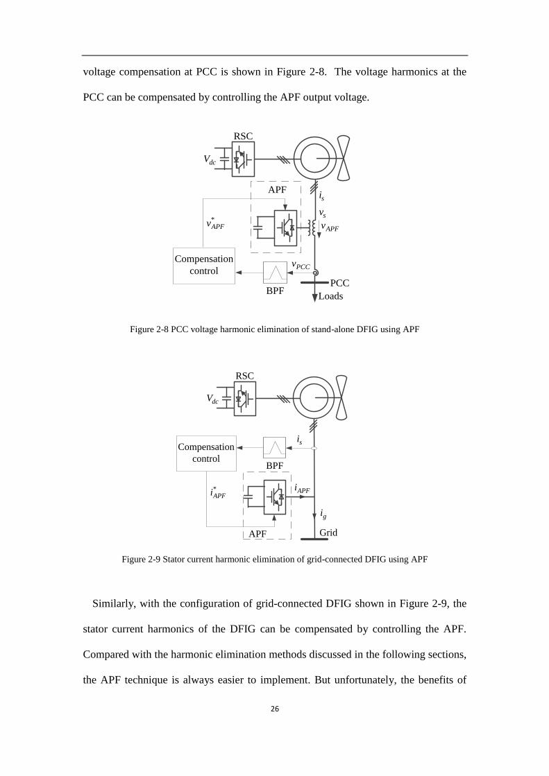
26
voltage compensation at PCC is shown in Figure 2-8. The voltage harmonics at the
PCC can be compensated by controlling the APF output voltage.
sv
si
dcV
LoadsBPF
APF
PCC
PCCv
RSC
APFv
Compensation
control
*APFv
Figure 2-8 PCC voltage harmonic elimination of stand-alone DFIG using APF
dcV
BPF
APF Grid
si
RSC
Compensation
control
*APFi APFi
gi
Figure 2-9 Stator current harmonic elimination of grid-connected DFIG using APF
Similarly, with the configuration of grid-connected DFIG shown in Figure 2-9, the
stator current harmonics of the DFIG can be compensated by controlling the APF.
Compared with the harmonic elimination methods discussed in the following sections,
the APF technique is always easier to implement. But unfortunately, the benefits of

27
APF technique are limited because one more converter is required to absorb the
harmonics. As a result, the cost of the system will be significantly increased. On the
other hand, the harmonic elimination by controlling RSC has become a potential way
forward. Thus, APF technique will not be considered for harmonic control unless
necessary.
2.2.3 PI controller for harmonic elimination
Based on the analysis in Section 2.2.1, in order to eliminate the harmonics in stator
current, one proposed control scheme is to produce a proper rotor current to
compensate the non-sinusoidal stator current and thus reduce the harmonics [14]. In
order to get a better performance in harmonic compensation, the 11th
and 13th
harmonic components are considered. Thus, to achieve this function, the 5th
, 7th
, 11th
and 13th
sequence harmonics of the stator current should be detected. Assume the
stator voltage and current are balanced. Thus, firstly, two current sensors are used to
detect the stator current. And eight band-pass filters are needed to extract the
harmonics from the current signals. After that, the harmonics in different orders are
transferred to the corresponding reference frames rotating with angular speed -5ωs,
7ωs, -11ωs and 13ωs
to get the dc value 5
5sdqi , 7
7sdqi , 11
11sdqi and 13
13sdqi , respectively.
Finally, to eliminate these harmonics, four PI controllers are applied to generate
reference harmonic sequence components of rotor voltage. The input of the PI
controller is the dc current harmonic error compared with zero. This controller could
generate the rotor current tracking the reference value and thus, a corresponding
proper stator current could be achieved and the harmonics can be reduced. The
proposed control scheme is shown in Figure 2-10.

28
+
dq
abcPWM
PI
dqabc
+
+
_
13, 13s dqV
7, 7s dqi
5, 5s dqi
11, 11s dqi
Band-pass filter
11*, 11r dqV
+
+
1*, 5r dqV
1*, 5,7,11,13r dqV dt
dt
d
d t
1*, 5,7,11,13r dV
1*, 5,7,11,13r qV
+
+
_
_
+
+
+
1,r di
1,r qi
1*,r dV
1*,r qV
*rV
r
s
r
*s
sl
ri
sl
sl1, ,r r d sl r dR i
1, ,r r q sl r qR i
+_
sV
si
dcV
_
+
_
+_
0
0
0
0
5*, 5r dqV
7*, 7r dqV
13*, 13r dqV
6 sje
12 sje
12 sje
+
+
6 sje
1*, 7r dqV
1*, 11r dqV
1*, 13r dqV
PI
PI
PI
PI
PI
1*, 1r dV
1*, 1r qV
5 sje
7 sje
11 sje
13 sje
1*, 1r di
1*, 1r qi
1,r qi
1,r di
+
+
_
_
Grid
Figure 2-10 Control scheme of the grid connected DFIG for stator current harmonic elimination using
PI controller
It could be found that with the traditional PI controller, the methods require large
amount of calculations because the elimination of the unbalanced or a given order
harmonic component each requires a BPF, a dq-frame followed by a reversed dq-
frame transformation between the corresponding rotating frequencies. What’s more,
the negative sequence component control loop should be included into the controller
in order to mitigate the unbalanced component.
2.2.4 PIR controller for harmonic elimination
An alternative method for harmonic control is using PIR technique [6, 16, 17, 54]. In
stand-alone DFIG, in order to reduce the harmonics in stator voltage, the proposed
controller using PIR technique in synchronous reference frame is shown in Figure 2-
11.

29
PI
+
_7, 7s dqv
5, 5s dqv
+
1*, 5r dqi _
+ 0
5*, 5r dqi
7*, 7r dqi
6 sje
+
1*, 7r dqi
PI
5 sje
7 sje
+
dq
abcPWM
dqabc
d/dt dt
dt
1*, 5,7r di
1*, 5,7r qi
+
+
+
++
+
+
1,r di
1,r qi
1*,r dv
1*,r qv
*rv
r
s
r
*s
sl
ri
sl
sl1, ,r r d sl r dR i
1, ,r r q sl r qR i
+_
sv
si
dcV
PIR
PIR
1*, 1r di
1*, 1r qi
1,r qi
1,r di
+
+
_
_
Loads
6 sje
0
BPF
1*, 5,7r dqv
Figure 2-11 Control scheme of stand-alone DFIG using PIR in synchronous frame
Similar to the control scheme of the grid connected DFIG for stator current harmonic
elimination, the control scheme of stand-alone DFIG using PIR control requires BPFs
to detect the 5th
and 7th
order of harmonics. After the harmonic components are
transferred into their corresponding reference frames, PI controller could be applied to
calculate the reference rotor current for harmonic compensation. The reference current
should be transferred into reference frame in which the reference rotor current will
contain periodical signals. Thus, in order to track the reference rotor current, resonant
loop should be included into the controller to regulate the periodical components.
This PIR controller could also be applied in stationary reference frame for stator
voltage harmonic elimination of stand-alone DFIG as shown in Figure 2-12. This
method is similar to the control scheme of stand-alone DFIG using PIR in
synchronous frame. But in stationary reference frame, the reference rotor current
contains periodical signals fundamental component, 5th
and 7th
harmonic
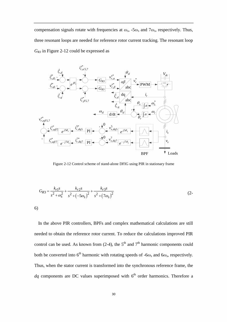
30
compensation signals rotate with frequencies at ωs, -5ωs and 7ωs, respectively. Thus,
three resonant loops are needed for reference rotor current tracking. The resonant loop
GR3 in Figure 2-12 could be expressed as
PI
+
_7, 7s dqv
5, 5s dqv
+
*, 5
sri
_
+ 0
5*, 5r dqi
7*, 7r dqi
sje
+
*, 7
sri PI
5 sje
7 sje
αβ
abcPWM
dq
abc
d/dt dt
dt
*, 5,7
sri
*, 5,7
sri
+
+
1,r di
1,r qi
*,
srv
*,
srv
*rv
r
s
r
*s
sl
ri
sl
sl
+_
sv
si
dcV
GR3
1*, 1r di
1*, 1r qi
1,r qi
1,r di
+
+
_
_
Loads
7 sje
0
BPF
*, 5,7
srv
5 sje
GR3
Figure 2-12 Control scheme of stand-alone DFIG using PIR in stationary frame
31 23 2 2 2 22 25 7
rr rR
s s s
k sk s k sG
s s s
(2-
6)
In the above PIR controllers, BPFs and complex mathematical calculations are still
needed to obtain the reference rotor current. To reduce the calculations improved PIR
control can be used. As known from (2-4), the 5th
and 7th
harmonic components could
both be converted into 6th
harmonic with rotating speeds of -6ωs and 6ωs, respectively.
Thus, when the stator current is transformed into the synchronous reference frame, the
dq components are DC values superimposed with 6th
order harmonics. Therefore a

31
proposed resonant control loop could be applied for harmonic compensation. The 6th
order harmonic resonant control transfer function is given by
22
2
2 6
r cR
c s
k sG
s s
(2-7)
In (2-7), kr is the resonant control gain and ωc is the cut-off frequency which
determines width of the resonant peak. In the synchronous reference frame, if the 6th
order harmonic resonant controller could achieve nearly zero steady-state error, the 5th
and 7th
order harmonics in the stator current could be eliminated if the commanded
value is set to zero. The proposed control scheme for stator current harmonic
elimination of grid-connected DFIG is shown in Figure 2-13.
GR
PI1
r rL s R m
s
L
L
1
s sL s j
22
2
2 6
r c
c s
K s
s s
*,r dqi ,r dqi ,s dqi
,s dqVDFIG
,r dqV
, ,5,7r dqV
,r dqE
*,r dqV
*,s dqi
Figure 2-13 Block diagram of stator current controller
The schematic representation of current control loop of the DFIG is shown in
Figure 2-14. In the fundamental reference frame, the fundamental components
become DC quantities and the 5th
and 7th
order harmonic components become AC
quantities with the sixth multiple of synchronous frequency. The resonant
compensator is capable of sufficiently tracking the AC reference current and it can

32
eliminate the steady-state control variable errors at the resonant frequency. According
to Figure 2-13, the closed-loop transfer function of stator current is determined as
* *, 1 , 2 , 3 ,( ) ( ) ( )s dq s dq r dq s dqi s G i s G i s G v s (2-8)
+
dq
abcPWM
dqabc
d/dt dt
dt
1*, 5,7r dv
1*, 5,7r qv
+
+
_
_
+
+
+
1,r di
1,r qi
1*,r dv
1*,r qv
*rV
r
s
r
*s
sl
ri
sl
sl1, ,r r d sl r dR i
1, ,r r q sl r qR i
+_
svsi
dcV
PI
PI
1*, 1r dv
1*, 1r qv
1*, 1r di
1*, 1r qi
1,r qi
1,r di
+
+
_
_
dq
abcGR
0+
_
GR
0+
_
1*, 5,7r qv
1*, 5,7r dv
s1,s di
1,s qi
GridHPF
Figure 2-14 Improved control scheme of the grid-connected DFIG using resonant loop
where G1, G2 and G3 are the transfer functions from commanded stator current,
commanded rotor current and stator voltage to actual stator current respectively.
According to Figure 2-13, these transfer functions could be expressed as
2,
1 *,
2
( )( )
s dq m r c
s dq
i s L k sG
N si s
(2-9)
2 2
,2 *
,
2 36
( )( )
m c s p is dq
r dq
L s s k s ki sG
N si s
(2-
10)

33
2 2
,3
,
2 36
( ) ( )
r r p i c ss dq
s dq s
s L s R k s k s si sG
v s s j N s
(2-11)
where characteristic polynomial N(s) is given as
2 2 2 2 2( ) 2 36 2 36 2s r r c s s c s p i m r cN s L s L s R s s L s s k s k L k s (2-
12)
In order to keep the control system stable and effective, the controller gains can be
determined by performing the analysis introduced in [56] using Naslin polynomial
technique.
The improved PIR technique could also be applied in stator voltage harmonic
elimination of stand-alone DFIG with the control scheme as shown in Figure 2-15.
+
dq
abcPWM
dqabc
d/dt dt
dt
1*, 5,7r di
1*, 5,7r qi
+
+
+
++
+
+
1,r di
1,r qi
1*,r dv
1*,r qv
*rv
r
s
r
*s
sl
ri
sl
sl1, ,r r d sl r dR i
1, ,r r q sl r qR i
+_
svsi
dcV
PIR
PIR
1*, 1r di
1*, 1r qi
1,r qi
1,r di
+
+
_
_
dq
abcGR
0+
_
GR
0+
_
1*, 5,7r qi
1*, 5,7r di
s1,s dv
1,s qv
LoadsHPF
Figure 2-15 Improved control scheme of the stand-alone DFIG using resonant loop

34
The analysis above all concern about the harmonic elimination control. For the
purpose of negative sequence component elimination in unbalanced load conditions,
some adjustments have to be made in PIR controllers. The proposed control scheme
for stator voltage unbalanced component elimination is shown in Figure 2-16. In
Figure 2-16, GRu is the resonant loop regulating the negative sequence component. In
this control scheme, the stator voltage is converted into synchronous reference frame
in which the negative sequence component is with rotating speeds of -2ωs. The
transfer function of GRu can be expressed as
+
dq
abcPWM
dqabc
d/dt dt
dt
1*,r dui
1*,r qui
+
+
+
++
+
+
1,r di
1,r qi
1*,r dv
1*,r qv
*rv
r
s
r
*s
sl
ri
sl
sl1, ,r r d sl r dR i
1, ,r r q sl r qR i
+_
svsi
dcV
PIR
PIR
1*, 1r di
1*, 1r qi
1,r qi
1,r di
+
+
_
_
dq
abc
0+
_
GRu
0+
_
1*,r qui
1*,r dui
s1,s dv
1,s qv
Loads
GRu
Figure 2-16 Improved control scheme of the DFIG using PIR for unbalanced component elimination
22 2
ruRu
s
k sG
s
(2-13)
As could be found according to the analysis above, the PIR technique can be used
for harmonic elimination of DFIG. Compared to the PI controller introduced in
Section 2.2.3, PIR control can deal with periodic components so that the calculation

35
can be simplified. For PIR techniques, it is important to choose a proper reference
frame and the controller design is strictly based on the frequencies of the harmonic
components in that reference frame. Harmonics in different orders have to be dealt
with separately. For the purpose of unbalanced component elimination, one more
resonant loop for negative sequence component control is required. Consequently, the
main drawback of PIR controller is that each resonant loop can only damp the
harmonic component corresponding to its resonant frequency.
2.2.5 PIRC controller for harmonic elimination
RC technique for periodic signal control is researched extensively recently [21, 57,
58]. Periodic signals of period T can be generated by the system shown in Figure 2-
17(a) while the basic RC loop is shown in Figure 2-17(b), where rck is the gain of the
loop, fG s is a phase lead compensator and Q is a low-pass filter which could be set
to be constant [19]. IRC(s) and ORC(s) are the input and output signals of the RC loop,
respectively. Thus, the transfer function of RC loop is
1
sTrc fRC
RC sTRC
k G s QeO sG s
I s Qe
(2-14)
In general, zero steady-state error tracking of an external periodic input can be
achieved by incorporating the RC scheme into a closed-loop system [59].

36
krc Qe-sT Gf(s)
+
+
e-sT
+
+
T T T T
(a)
(b)
RC LoopIRC(s) ORC(s)
Figure 2-17 (a) Generator of periodic signal, (b) RC loop
A hybrid control scheme with traditional PI controller and RC for the purpose of
harmonic compensation of a grid-connected inverter is introduced in [19]. The control
scheme for harmonic elimination in synchronous frame of the inverter is shown in
Figure 2-18. In this control scheme, the fundamental component is usually controlled
for DC voltage regulation which is not our concern in this section. The harmonic
component is controlled in synchronous frame in which the 5th
and 7th
harmonics are
with rotating speeds of -6ωs and 6ωs, respectively. But according to the bode diagram
of PIRC, the controller can damp periodic components with rotating speed of integral
multiples of fundamental frequency. With this in mind, it is noticed that regardless of
the reference frame, the PIRC could be used for harmonic elimination control. For the
harmonic elimination of the inverter shown in Figure 2-18, the control scheme of
PIRC in stationary reference frame is shown in Figure 2-19.

37
Grid
PI
e-sTGf(s)
++
PWM
krc
*dqi
RC Loop GRC+
+
+
_
Control of inverter
L iR
dq
abc
sdqidq
abc
s
Figure 2-18 Three-phase grid-connected inverter with hybrid PIRC control scheme in synchronous
frame
In stationary frame, the fundamental component rotates with fundamental frequency
and the 5th
and 7th
harmonic components rotating with frequencies as 5 and 7
multiples the fundamental frequency so that RC loop can be applied for both
fundamental and harmonic components control. Thus, compared with the PI and PIR
control for harmonic elimination, PIRC is simpler and with less calculation burden.
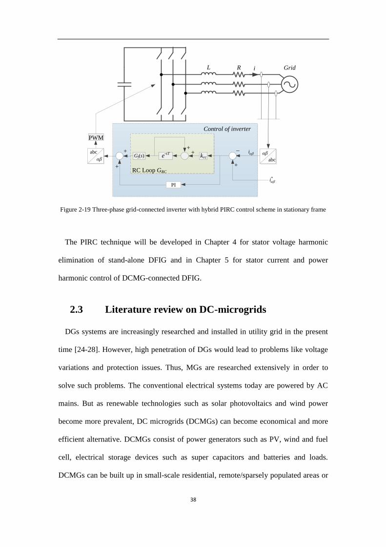
38
Grid
e-sTGf(s)
++
PWM
krc
*i
RC Loop GRC
+
+
_
Control of inverter
L iR
αβ
abc
i
αβ
abc
+
PI
Figure 2-19 Three-phase grid-connected inverter with hybrid PIRC control scheme in stationary frame
The PIRC technique will be developed in Chapter 4 for stator voltage harmonic
elimination of stand-alone DFIG and in Chapter 5 for stator current and power
harmonic control of DCMG-connected DFIG.
2.3 Literature review on DC-microgrids
DGs systems are increasingly researched and installed in utility grid in the present
time [24-28]. However, high penetration of DGs would lead to problems like voltage
variations and protection issues. Thus, MGs are researched extensively in order to
solve such problems. The conventional electrical systems today are powered by AC
mains. But as renewable technologies such as solar photovoltaics and wind power
become more prevalent, DC microgrids (DCMGs) can become economical and more
efficient alternative. DCMGs consist of power generators such as PV, wind and fuel
cell, electrical storage devices such as super capacitors and batteries and loads.
DCMGs can be built up in small-scale residential, remote/sparsely populated areas or

39
commercial/data centers. Nowadays, many renewable sources generate DC, such as
photovoltaic, wind and fuel cells. Compared to grids, when supplied with DC sources
the conversion efficiency of DCMGs is higher. Moreover, DC power can be easily
stored in batteries. As a result, it is predicted that DCMG will be applied increasingly
in the future [30].
A typical DCMG consists of distributed nodes. Each node can be comprised of
sources, energy storage devices and loads. Different nodes are connected by
distribution lines. Each node in the DCMG can be regarded as a unit which delivers or
absorbs power from the DCMG.
The power management of DCMG is greatly discussed in the previous literatures.
The power flow will be determined by the voltage distribution in the DCMG. A
common voltage control method has been proposed in [64-68] using grid converters
(GCs). In this method, the excess power from the distributed generators or load
demand will be absorbed or met by GC. As an alternative method, a large source like
a synchronous generator with a large capacity to support the voltage is proposed.
More recently, the voltage control by distributed sources is proposed in isolated
DCMGs. This method can improve the power flow control but the control of the
distributed generators need communications.
Importantly, it is described in Section 1.1 that DFIG is more attractive from an
economical point of view because the power converter of the DFIG only handle 20%
to 30% of the total power. However, there are many problems associated with DFIG
interfaced AC power systems. For example, with the integration of large-scale wind
farms, the operating frequency of power grid will be impacted due to the lack of
frequency regulation support from wind turbines which is caused by the decoupling
control system in DFIGs [60, 61]. Therefore, a significant number of recent research

40
works have proposed that DFIGs can be connected to DCMGs to overcome the
frequency regulation problem. Moreover, the LVRT problems associated with DFIGs
discussed in Section 2.1 will no longer exist because the DCMG doesn’t require
reactive power.
When the DFIG is connected to the DCMG, a new scheme is needed to convert the
AC power from DFIG to DC power to be consumed by the loads on DCMG.
Although certain previous research work shave proposed some new configurations of
DFIG interface to DCMGs, unfortunately, DFIGs will lose their benefits in some of
the proposed configurations. A novel configuration will be discussed in Chapter 5 and
the harmonic problem in the new configuration will be solved using PIRC introduced
in Section 2.2.
In order to achieve a better stability of the system, equitable load sharing and stable
DC voltage at each node is required. Moreover, it is also necessary to deal with the
condition that arises when the sources are cut off in some nodes. In such a condition,
it is required that the DC voltage at each node needs to be kept stable and the load
sharing should be adjusted.
2.3.1 DCMG voltage controlled by GC
In DCMGs, the DC voltage regulation is a key concern. Voltage control methods
have been discussed by many researchers. In gird-connected DCMG shown in Figure
2-20, it is proposed that the voltage is controlled by a GC.
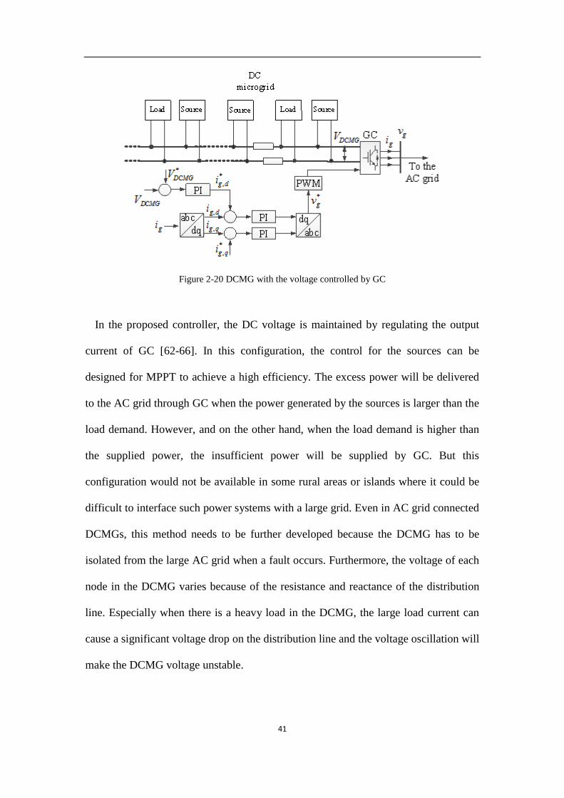
41
Figure 2-20 DCMG with the voltage controlled by GC
In the proposed controller, the DC voltage is maintained by regulating the output
current of GC [62-66]. In this configuration, the control for the sources can be
designed for MPPT to achieve a high efficiency. The excess power will be delivered
to the AC grid through GC when the power generated by the sources is larger than the
load demand. However, and on the other hand, when the load demand is higher than
the supplied power, the insufficient power will be supplied by GC. But this
configuration would not be available in some rural areas or islands where it could be
difficult to interface such power systems with a large grid. Even in AC grid connected
DCMGs, this method needs to be further developed because the DCMG has to be
isolated from the large AC grid when a fault occurs. Furthermore, the voltage of each
node in the DCMG varies because of the resistance and reactance of the distribution
line. Especially when there is a heavy load in the DCMG, the large load current can
cause a significant voltage drop on the distribution line and the voltage oscillation will
make the DCMG voltage unstable.

42
Figure 2-21 DCMG with its voltage controlled by CSG
2.3.2 DCMG voltage controlled by a large source
As shown in Figure 2-21, an alternative configuration for the DCMG is proposed in
[34]. A synchronous generator is installed in the DCMG and the DC voltage is
maintained by control of converter of synchronous generator (CSG). The d-axis of
generator current is regulated for DCMG voltage control and the q-axis is for reactive
power control of the synchronous generator. The generator will stop providing active
power to the DCMG when the power generation in the DCMG is greater than the load
demand. The energy storage system in the DCMG will absorb the excess power. The
synchronous generator will generate power to the DCMG when there is no sufficient
power generation from existing sources for the load demand.
This configuration can solve the problem that in some rural areas or islands where it
is hard to interconnect the power system with a large grid while the other sources in
the DCMG can be controlled for MPPT to achieve a high efficiency. But this

43
configuration requires a synchronous generator with a large capacity to support the
grid. It makes the cost of the system significantly high to operate the DCMG in such a
configuration. Furthermore, similar to the grid-connected DCMG, the voltage stability
cannot be guaranteed. The operating point of the synchronous generator changes with
the mismatch between the power generation and load demand. Alternatively, a large
capacity energy storage can be installed in place of the synchronous generator to
handle the mismatch between the supply and demand. However, the cost of energy
storage will increase with its power rating significantly. Therefore, it is necessary to
improve the control scheme of the distributed sources as an effective way to avoid the
frequent change of synchronous generator operating point or as an alternative for the
use of large capacity energy storage. The proposed control scheme of the distributed
sources will be discussed in Chapter 5 in great detail.
2.3.3 DCMG voltage controlled by distributed source
Figure 2-22 Configuration of a DCMG-connected DFIG with individual voltage control

44
More attractive control method for DCMG voltage control by distributed sources
has been reported in [69]. As shown in Figure 2-22, sources and storage elements are
controlled to supply high reliability power to loads. The DCMG voltage control
method by distributed sources can be used when the DCMG either in isolated or AC
grid connected mode. A traditional voltage control method for the distributed sources
is to reduce the power loss in the distribution line as much as possible. In this method,
the voltage at each node of the DCMG will be controlled with a same reference value
so that the current flow through the distribution line will be reduced. This method
reduces the power loss but unfortunately, the mismatch between the power generation
and load demand will affect the performance badly. For example, in the DCMG, in
some nodes the load demand can be smaller than the power generation and some
nodes otherwise. In such nodes the load demand is lower than the power generation,
an ESS with a large capacity should be used to absorb the excess power in the node.
Otherwise, the power generation of the local source has to be reduced. Conversely, if
the load demand is larger than the power generation, the ESS should supply power to
meet the demand but when the ESS is fully discharged, some loads have to be shed to
reduce the burden of the sources. But if an equitable load sharing is applied, the
excess power in some nodes can be delivered to those nodes where there is shortage
of power.
In this configuration of DCMG, droop control can be applied in the DCMG voltage
regulation and thus, the voltage can be kept more stable and the reliability of the
DCMG can be improved. However, the control of DCMG without communication as
shown in Figure 2-22 will lead to an unequal load sharing due to error in normal
voltages or load distribution in DCMG. Thus, the configuration and control scheme of
such system need to be improved.

45
Moreover, in DCMGs, renewable energy plays an important part in the power
supply. If renewable energy sources are used for voltage regulation, it will lose the
MPPT control and the efficiency of the sources will be reduced. Also, as such sources
are intermittent in nature, voltage regulation may not become possible at certain
source conditions. As a result, ESS needs to be installed into the nodes and used for
voltage control. In such a scenario, renewable energy sources can be used to achieve
MPPT. Therefore, a novel configuration of DCMG which consists of sources of BESS
and DFIGs is proposed along with improved droop control and it is discussed in detail
in Chapter 5. In order to improve the efficiency, the DFIGs are controlled for MPPT.
And for the purpose of equal load sharing and stable DC voltage, the DCMG voltage
is regulated by BESS using improved droop control.
2.3.4 DCMG-connected DFIG with a fully rated converter
The configuration of the DCMG-connected DFIG is another concern in this
research. A configuration of DCMG-connected DFIG is proposed in [63] whence the
AC power of the DFIG is delivered to the DCMG by a GSC. As shown in Figure 2-23,
the GSC controls the stator voltage of the DFIG so that the AC power of the generator
can be delivered to the DCMG. The power generated by the DFIG will be delivered to
the DCMG through a GSC and the power rating of GSC is higher than the rated
power of the DFIG.
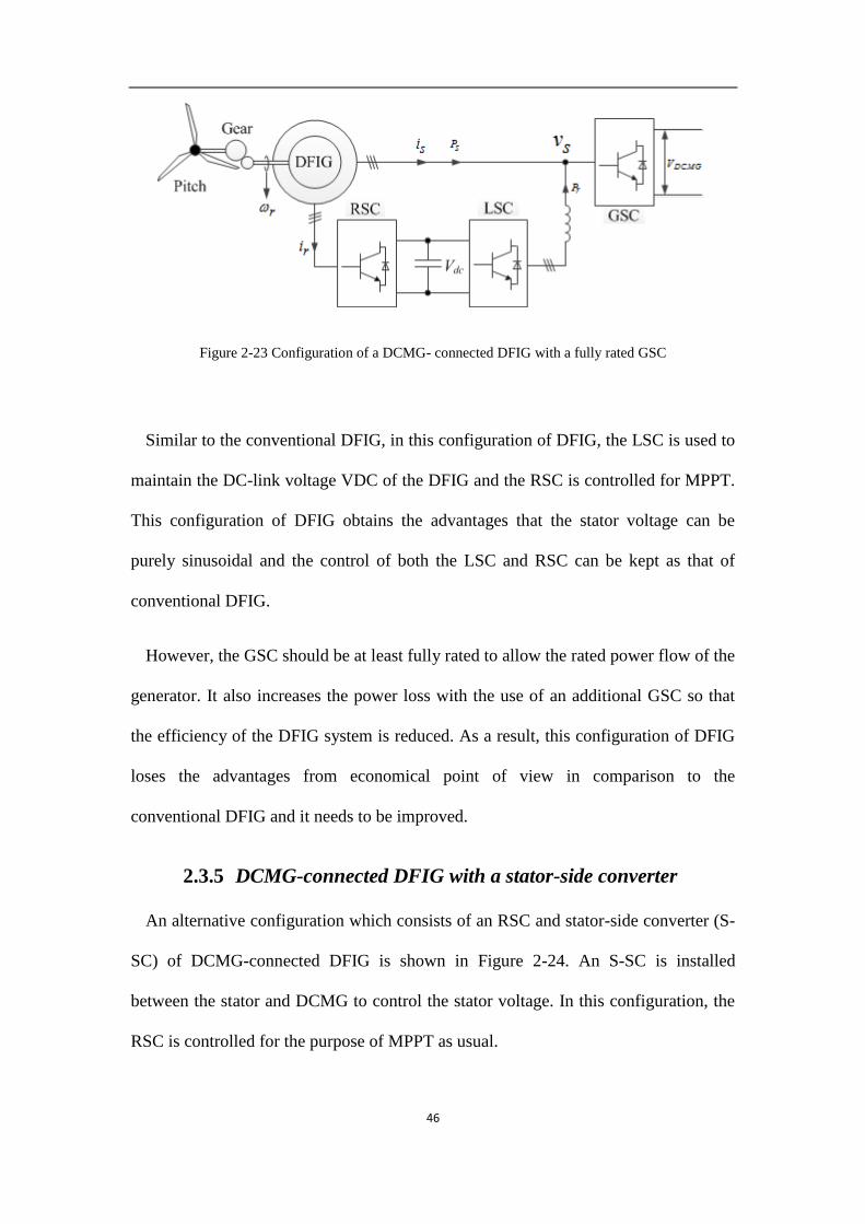
46
Figure 2-23 Configuration of a DCMG- connected DFIG with a fully rated GSC
Similar to the conventional DFIG, in this configuration of DFIG, the LSC is used to
maintain the DC-link voltage VDC of the DFIG and the RSC is controlled for MPPT.
This configuration of DFIG obtains the advantages that the stator voltage can be
purely sinusoidal and the control of both the LSC and RSC can be kept as that of
conventional DFIG.
However, the GSC should be at least fully rated to allow the rated power flow of the
generator. It also increases the power loss with the use of an additional GSC so that
the efficiency of the DFIG system is reduced. As a result, this configuration of DFIG
loses the advantages from economical point of view in comparison to the
conventional DFIG and it needs to be improved.
2.3.5 DCMG-connected DFIG with a stator-side converter
An alternative configuration which consists of an RSC and stator-side converter (S-
SC) of DCMG-connected DFIG is shown in Figure 2-24. An S-SC is installed
between the stator and DCMG to control the stator voltage. In this configuration, the
RSC is controlled for the purpose of MPPT as usual.

47
Figure 2-24 Configuration of a DCMG-connected DFIG with a stator-side converter (S-SC)
Compared with the DCMG-connected DFIG with fully rated GSC, this improved
configuration of DFIG could have a lower cost because it saves one converter.
However, the co-operation of the S-SC and RSC is required which makes the
controller to be increasingly complex. Furthermore, the S-SC should be fully rated
because the stator power flow through S-SC could be as high as the rated power of
DFIG. This disadvantage makes this configuration of DFIG to be costly that it
requires further improvement
Based on this configuration, an improved configuration of DFIG has been proposed
in [34]. In [34], the S-SC is replaced by an SSR. It keeps the cost of DFIG to a low
value. However, it introduces some power quality problems. The uncontrollable SSR
will lead to a distorted stator voltage and armature current. Therefore, the distortion
has to be compensated which will be discussed in detail in Chapter 5.

48
Chapter 3. Design of Mode Switching Scheme for
Low Voltage Ride Though of DFIG
In this chapter, a mode switching technique is proposed for grid connected DFIGs.
In this technique, the DFIG is to switch from the conventional DF connection to the
IG connection or vice versa, depending on the status of the DFIG terminal voltage.
When a grid fault occurs and the DFIG terminal voltage is depressed, the DFIG is to
operate in the IG mode. The stator windings are disconnected from the grid and the
winding terminals are subsequently short circuited. This is done because the rotor
transient current has an almost linear relationship with the stator current when the
fault occurs. Thus by changing to the IG connection, the rotor current would be
unaffected by the grid voltage because the stator is isolated from the grid. The
desirable feature of this scheme over the other LVRT methods is that the generator
remains connected to the grid through the rotor circuit.
Hence, compared to the commonly used LVRT technique introduced in [8, 53], the
advantages of MSDFIG can be summarized as follows [34].
Generator control: Because of the RSC is disconnected from the DFIG when fault
occurs, the commonly used LVRT technique loses the control of the generator during
LVRT which is dangerous for the generator especially in high rotor speed conditions.
On the other hand, MSDFIG is still under control even in grid fault conditions.
Reactive power control: The GSC is controlled within the power rating of the
converter for reactive power control. The MSDFIG can achieve this aim too. However,
the MSDFIG takes the advantage that the reactive power that is delivered to the grid

49
can be much larger than that of the method introduced in [53] because the
uncontrolled generator in [53] may absorb large amount of reactive power in grid fault
conditions [13].
Generator isolation: In the previous LVRT techniques like in [53], the stator of the
generator is connected to the grid directly without protection and the generator is out
of control. The possible voltage oscillation of the grid during grid fault conditions
may be harmful for the generator. In MSDFIG, this negative effect can be avoided
due to the isolation of the generator from the grid. The real power can also be
generated and delivered to the grid in grid fault condition which is also a creative
feature of MSDFIG compared to the other techniques.
Back to Back
Converters
FilterWind
Turbine
Three Phase Fault
CB
PCC
DFIGLarge grid
Figure 3-1 Schematic of a grid-connected DFIG
3.1 DF and IG modes: basic circuit models
The schematic of a grid-connected DFIG is shown in Figure 3-1. The prime mover
is a wind turbine controlled to generate the maximum mechanical power in
accordance to the wind speed. The induction generator converts the mechanical power
to electrical form which is then delivered to the grid through both the stator and the
rotor windings. Figure 3-1 shows a transmission line-transformer electrical link
interconnecting the DFIG to a large grid. This rather generic network can be used to
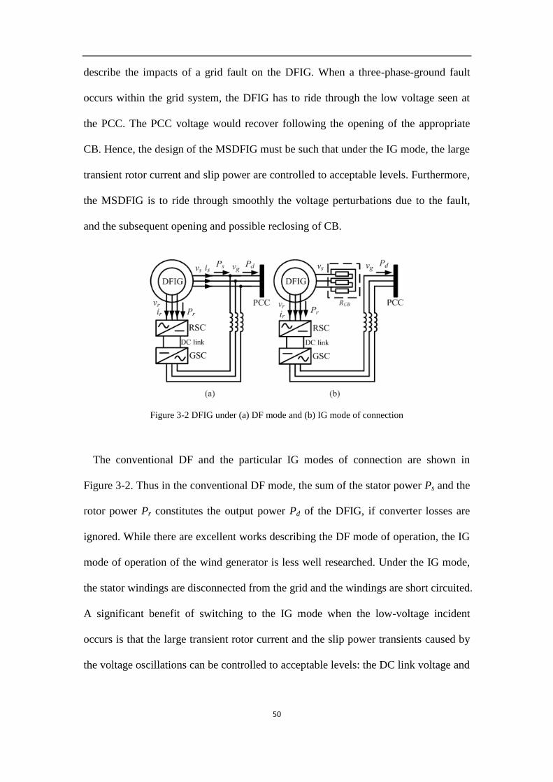
50
describe the impacts of a grid fault on the DFIG. When a three-phase-ground fault
occurs within the grid system, the DFIG has to ride through the low voltage seen at
the PCC. The PCC voltage would recover following the opening of the appropriate
CB. Hence, the design of the MSDFIG must be such that under the IG mode, the large
transient rotor current and slip power are controlled to acceptable levels. Furthermore,
the MSDFIG is to ride through smoothly the voltage perturbations due to the fault,
and the subsequent opening and possible reclosing of CB.
Figure 3-2 DFIG under (a) DF mode and (b) IG mode of connection
The conventional DF and the particular IG modes of connection are shown in
Figure 3-2. Thus in the conventional DF mode, the sum of the stator power Ps and the
rotor power Pr constitutes the output power Pd of the DFIG, if converter losses are
ignored. While there are excellent works describing the DF mode of operation, the IG
mode of operation of the wind generator is less well researched. Under the IG mode,
the stator windings are disconnected from the grid and the windings are short circuited.
A significant benefit of switching to the IG mode when the low-voltage incident
occurs is that the large transient rotor current and the slip power transients caused by
the voltage oscillations can be controlled to acceptable levels: the DC link voltage and
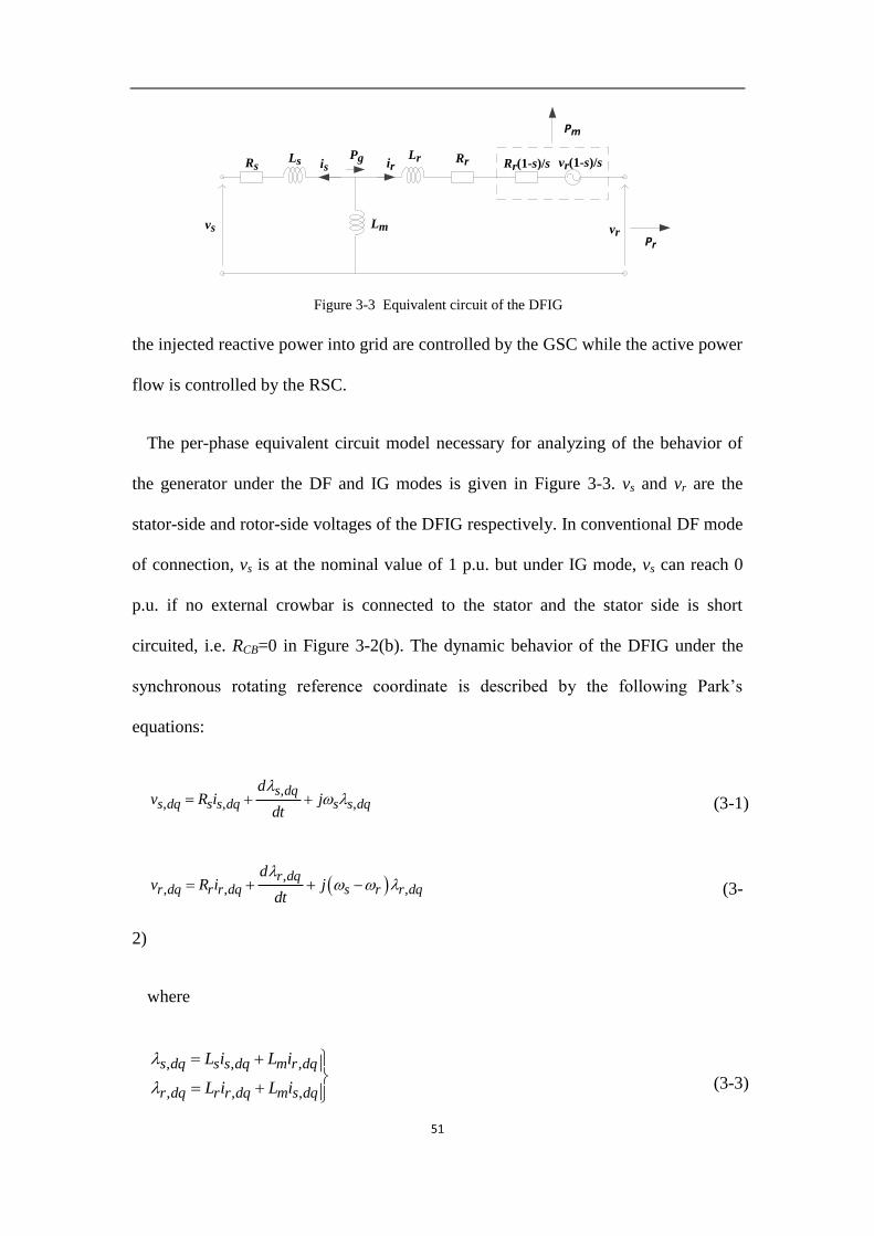
51
the injected reactive power into grid are controlled by the GSC while the active power
flow is controlled by the RSC.
The per-phase equivalent circuit model necessary for analyzing of the behavior of
the generator under the DF and IG modes is given in Figure 3-3. vs and vr are the
stator-side and rotor-side voltages of the DFIG respectively. In conventional DF mode
of connection, vs is at the nominal value of 1 p.u. but under IG mode, vs can reach 0
p.u. if no external crowbar is connected to the stator and the stator side is short
circuited, i.e. RCB=0 in Figure 3-2(b). The dynamic behavior of the DFIG under the
synchronous rotating reference coordinate is described by the following Park’s
equations:
,, , ,
s dqs dq s s dq s s dq
dv R i j
dt
(3-1)
,
, , ,r dq
r dq r r dq s r r dq
dv R i j
dt
(3-
2)
where
, , ,
, , ,
s dq s s dq m r dq
r dq r r dq m s dq
L i L i
L i L i
(3-3)
Pr
Pm
vs
Rr(1-s)/s
vr
Rr
Lm
RsPgLs
Lr vr(1-s)/sis ir
Figure 3-3 Equivalent circuit of the DFIG

52
In these equations, is,dq and ir,dq are the respective stator and rotor currents in the d-q
reference frame. Rs, Ls, Rr and Lr are the stator and rotor resistances and inductances
respectively. Lm is the generator magnetizing inductance. ωs and ωr are the stator-side
frequency and rotor speeds. Equations (3-1) – (3-3) allow the behavior of the wind
generator to be studied, as follows.
3.2 Analysis of transient current
From (3-1) – (3-3), it can be readily shown that the voltage equations for an
induction generator in synchronous reference frame are given by
, ,
, ,
s s s s s s dq s m m r dq
r r s r r r r dq s r m m s dq
d dv t R j L L i t j L L i t
dt dt
d dv t R j L L i t j L L i t
dt dt
(3-4)
As the converters must be protected against rotor circuit over-load, the following
analysis is carried out in order to quantify the magnitude of the rotor transient current
which will in turn lead to a proposed technique to limit the current.
3.2.1 DF to IG Mode Switch
When the induction generator switches from the DF to IG modes, the stator
terminals are connected to a crowbar in the present scheme. In the following
derivation and without any loss of generality, the crowbar resistance is merged into
the stator winding resistance to yield the total stator resistance Rs. Furthermore, in
order to simplify analysis, it is assumed that within the very short time when the
generator switches from the DF to IG modes of operation, vr and ωr are constant.
Hence, vs changes from 1 p.u. to zero when the generator switches from the DF to the
IG mode. Apply Laplace transformation to (3-4), the voltage equations become

53
, ,
, ,
1s s s s s dq m s m r dq
rr r s r r r dq m s r m s dq
R L p j L i L p j L ip
vR L p j L i L p j L i
p
(3-5)
where p is the Laplace operator.
The transient rotor current can be shown to be of the form
1 2, 0 1 2
t tr dqi C C e C e
(3-6)
where the parameters ξ1, ξ2, C0, C1 and C2 can be determined using (A-3) and (A-4)
shown in Appendix 3-A.
3.2.2 Technique to Limit the Transient Current
The results of the above analysis show a possible way to limit the rotor transient
current is through the use of SSC which is represented by RCB as shown in Figure 3-4.
The SSC is used to limit the rotor inrush current. Unlike the use of rotor-side crowbar
in the conventional design, the DFIG can still be controlled using the SSC.
In the design of the MSDFIG, the stator crowbar will only be activated by closing
switch S3 when the generator switches from the DF to IG modes. The crowbar limits
the transient rotor current by dissipating the real power appearing in the transients.
Subsequently the stator shall be disconnected from the grid through the opening of the
switch S1 and the resistance of the crowbar RCB shown in Figure 3-2(b) in the stator
circuit will be continuously reduced as the generator progresses toward a steady state
in the IG mode. The reduction in resistance is achieved by controlling the duty-ratio D
of the IGBT T1 shown in Figure 3-4. Thus, the equivalent resistance of RCB can be
expressed as

54
1
1
* 1syn CB
CBsyn CB
R RR D
R R
(3-7)
During the re-synchronization stage of the generator however, RCB has to be of
much higher value. So the relatively lower resistance (RCB1) will be disconnected from
the stator circuit through the opening of the switch S2. Effectively, the synchronization
resistor (Rsyn) shown in Figure 3-4 shall be inserted. Thus, the switches S1, S2 and S3
are envisaged to be electric-mechanical, power electronic and electric-mechanical
switches, respectively.
MSDFIG under the synchronization mode will be discussed in greater details in
Section 3-4.
Figure 3-4 DFIG with a stator-side crowbar (SSC)
3.3 Controllers design
The controllers for the MSDFIG operate under three possible scenarios. Under
normal grid conditions, the DFIG is controlled to maximize energy harness from the
wind. Under grid-fault condition however, the stator crowbar circuit is activated and

55
the DFIG switches to the IG mode of connection during which the active power flow
through the converters is controlled to within the power ratings of the converters.
Following grid-fault clearance, the DFIG switches to the re-synchronization mode for
which the amplitude, frequency and phase of the stator-side voltage vector Vs is
controlled in synchronous reference frame to track the grid-side voltage vector Vg .
When V Vs g , S1 shown on Figure 3-4 shall close and S2 and S3 open. Thus, the DFIG
will revert back to the DF mode and normal operation resumes.
3.3.1 Controller for the GSC
The GSC controller is similar to that shown in [67]. Under normal conditions, the
GSC is controlled to maintain the DC-link voltage through the manipulation of the d-
axis current Id and to ensure active power generated by the generator is fed to the grid.
Under the IG mode and through the control of the q-axis rotor current, the GSC also
controls the reactive power flow to the grid. Reference [67] provides a good
discussion on the reactive power requirements. MSDFIG can generate and deliver
reactive power to the grid and stays well within the power rating of the GSC when the
grid fault occurs, based on the same reactive power control method as used in several
LVRT techniques [5]. However, the proposed MSDFIG has distinct advantages over
these conventional techniques, as shall be shown below.
3.3.2 Controller for the RSC
The schematic diagram of the control system for the RSC is shown in Figure 3-5.
The stator and grid voltage are measured to decide the mode of the controller. In
normal condition, the controller is in mode 1 (DF mode). When the stator and grid
voltage is less than a lower limit of (say) 0.9 p.u., the controller will be switched to

56
mode 0 (IG mode). If it is detected that the grid voltage recovers, the controller will
be switched to mode 2 (synchronization mode). After the synchronization is achieved
the controller will be switched to mode 1. Under DF or mode 1, MPPT applies for real
and reactive power control to achieve unity power factor. Under IG or mode 0, the
rotor-side real power is regulated. The control system is designed so that the reactive
power required to the gird shall be met while the rotor-side real power is controlled to
ensure the apparent power delivered to the grid is within the rating of the GSC. In the
synchronization or mode 2, the stator voltage is controlled for smooth and quick re-
connection to the grid.
Figure 3-5 Control schematic for rotor-side converter
Under the IG Mode
The RSC is controlled by a vector controller in the stator reference frame. Under the
IG mode, the DFIG can still be controlled to generate real power during fault and this

57
is a distinct advantage over other proposed schemes. The d-axis rotor current is
controlled to regulate the active power flow through the converters.
By applying the equivalent circuit shown in Figure 3-3, one obtains
21Rem r r r r
sP i R v i
s
(3-8)
where Pm is the input mechanical power and s is the slip value. The rotor real power
flow Pr and rotor losses Pr,loss are given by
Rer r rP v i (3-9)
2,r loss r rP i R (3-10)
The relationship between the input mechanical power and output rotor power can be
derived as
,1
r m r losss
P P Ps
(3-11)
where /s r ss . Based on the power flow directional convention shown in
Figure 3-3, the mechanical power Pm is negative while the rotor power Pr is positive
under the IG mode. Whence
1 01
s
s
(3-12)
That is, the slip s must be negative. In the IG mode, it is desirable to increase the
ratio /r sP P such that the power loss in the stator circuit would be minimized as in

58
this way, the stator current can be reduced. Hence, s should be much less than zero
and the DFIG needs to work in the highly super-synchronous region. To achieve the
super-synchronous operation, one can either increase the rotor speed or decrease the
stator frequency. Increasing rotor speed is not an acceptable option because of the
large response time caused by the rotor inertia, as well as the upper limit placed on the
rotor speed due to mechanical considerations. So the decrease of the stator frequency
becomes the only way to increase the rotor output power. Given that the active power
flow through the converters has to be below the power rating of the converters, the
reference stator frequency *,s fault can be determined, as described below.
In IG mode, the machine becomes an inverter-fed induction generator. The
equivalent circuit of the generator rotor reference frame is shown in Figure 3-6 where
2 2/ra and ω2 is the frequency of the input voltage of the RSC. If the rotor
losses are ignored, then the power delivered to the rotor-side converter equals to air-
gap power, i.e. Pr=Pg. The air-gap power of the generator can be shown to be
22
2 22
3 /3
/
s s sg r
s s
R i R aP v
a R a L
(3-13)
To keep Pr under the power ratings of the converters, the rotor-side frequency ω2
could be determined under different rotor speed conditions. Thus, a look-up table of
ω2 under different rotor speed ωr conditions can be constructed so that under the IG
mode, ω2 can be readily determined once ωr is known. Thus one can safely set the slip
to be fixed in the operation region of the DFIG to keep Pr within the power ratings of
the converters.

59
Pr
Pm
Rs(1-a)/a
Vr
Rr
Lm
PgLs Lr
Rs
Figure 3-6 Equivalent circuit of the DFIG in the IG mode
Synchronization Control
After fault clearance and voltage recovery is detected, the generator is to recover
from the IG to the DF modes of operation. As shown in [12], direct reconnection of
the stator to the grid could lead to large and persistent oscillations in Pd. The problem
can be obviated by synchronizing sv with gv before 1S is reclosed. Indeed, several
methods have been reported in the literature concerning grid synchronization of DFIG.
See e.g. [68]. Unfortunately the control strategies tend to be rather complex. Instead,
the much simpler PI controller shown in Figure 3-5 is used in this thesis to show that
it can perform sufficiently well for the problem in hand. To achieve the
synchronization, it is required to track the grid voltage space phasor. Therefore, the
grid voltage oriented reference frame shall be specified for the design of the
synchronization controller. The d-axis of the synchronous reference frame is aligned
to the grid voltage, i.e.
,
, 0
g d g
g q
v v
v
(3-14)
The stator windings are open-circuited when the DFIG is in grid synchronization
mode. However, when the generator is switched from the IG mode to grid

60
synchronization mode, the stator windings are switched from short circuit to open
circuit. The stator current would be reduced to zero in the transient process. Special
precaution has to be taken because the sudden current reduction would lead to a large
voltage across the stator inductance. Thus, under the synchronization mode, S2 is open,
S3 is still closed and T1 is open. The resistance of stator crowbar shall be
CB synR R (3-15)
The synchronization crowbar has a large resistance value to maintain the stator
voltage in the synchronization mode.
Prior to the synchronization, one can assume a very low stator current. Then, the
equations describing the operation of the DFIG in the synchronization mode based on
the synchronous reference frame are (3-1) – (3-2). Since it is demanded the stator
voltage equals to the grid voltage, i.e., s gv v , then from (3-15), one obtains
*,
*, 0
s d g
s q
v v
v
(3-16)
Switching sequence
The switching sequence of S1, S2 and S3 are shown in Figure 3-7. Under normal grid
conditions, S1 and S2 are closed and S3 is open. The DFIG is in DF mode. When a grid
fault is detected, S1 is switched off and S3 is switched on, S2 is kept closed. The
crowbar is thus inserted into the stator circuit and the generator is switched to IG
mode. When the grid voltage has recovered, S2 is switched off and RSC is under
synchronization control. S1 is kept opened and S3 is kept closed. After the

61
synchronization has been reached, the crowbar circuit is disconnected by opening S3.
S1 is reclosed and the generator is back to DF mode of connection.
Grid condition
S1
S2
S3
NormalFaulty
1
0
1
0
0
1
Synchronization
IG modeDF mode DF mode
Figure 3-7 Switching sequences of S1, S2 and S3. (1 stands for switch on and 0 stands for switch off)
3.4 Control of crowbar resistance
Given the initial power Pd delivered to the grid and power factor (pf), the initial
conditions of , , r s ri i and vr can be determined as shown in Appendix 3-B. Then
using the derived expressions shown in Section 3.3, the transient rotor current passing
through the RSC can be determined. This can be most conveniently illustrated using
the numerical example of a DFIG which has the parametric values shown in Table 3-1.

62
3.4.1 Transient Currents Limitation
Figure 3-8(a) shows the transient rotor current under a range of initial active power
Pd. It shows that the higher the initial Pd, the larger would be the transient rotor
current. When the DFIG output apparent power S is fixed at 1 p.u., Figure 3-8(b)
shows the transient rotor current when the DFIG operates initially over a range of pf
of between 0.9 (lagging) to 0.9 (leading). It is seen that larger transient current would
occur under the leading pf operating conditions. Hence, the largest transient current
would be under the highest initial S and at the pf of 0.9 (leading). This worst-case
scenario was studied in greater detail by examining the effect of the effective stator
resistance on the rotor transient current. The results are shown on Figure 3-8(c). The
stator-side effective resistance includes the stator winding resistance which is 0.02 p.u.
Table 3-1 Parametric Values of a 1.5-MW, 60-Hz, 380-V 6-Pole Wound Rotor Induction Machine
Parameter Value Parameter Value
Lm 2.9 p.u. r2 0.02 p.u.
L1 3.09 p.u. RCB1 1.8 p.u.
L2 3.09 p.u. Rsyn 10 p.u.
r1 0.02 p.u. Vdc 1150 V
(a) (b)
(c) (d)
Figure 3-8 Transient rotor current under a range of (a) initial active power Pd at pf = 1, (b) power factor for
apparent power S = 1 p.u., (c) stator resistance for S = 1 p.u. and pf = 0.9 (leading) and (d) Crowbar resistance
control for various initial Pd at pf = 0.9 (leading)

63
and the crowbar resistance which is assumed variable from 0 to 1.5 p.u. Thus
0.02 1.52 p.u.sR The figure shows that the smaller the value of RS, the higher would
be the rotor transient current. Thus, the results suggest that transient rotor current can
be reduced by increasing the stator resistance.
3.4.2 Control Strategy of Crowbar Resistance
Unfortunately, it is also noted that increasing the resistance leads to a longer settling
time for the rotor current transients. A variable resistance scheme appears to be
desirable. This possibility is explored, as follows.
Equation (3-13) shows that the ability of the generator to output active power to
support the grid becomes less than desirable, if the crowbar resistance is kept high.
Thus, at the early stage when the generator switches from the DF to IG mode, the SSC
resistance should be kept high to limit the peak transient current. After the initial large
transient current has been subdued, the resistance should be reduced so as to minimize
the settling time of the current. Based on this observation, the strategy to adjust the
resistance can be illustrated using the results of Figure 3-8(c). In view of the converter
current limit, suppose the peak value of the transient current should not exceed 3 p.u.
From Figure 3-8(c), a suitable initial crowbar resistance setting is 1.4 p.u.
approximately. One convenient way to demonstrate the effect of the crow-bar
resistance on the rotor current, as a function of elapsed time of the application of the
resistance is shown on Figure 3-9. In this figure, the contours of rotor current of
various levels are plotted as functions of the crowbar resistance and time. In this
example for the case of rated output power at 0.9 leading pf, it shows that when the
crowbar resistance is set at 1.4 p.u. for about 0.07 s, the rotor current is controlled and
guaranteed to be below the 3 p.u. threshold. After 0.07 s, the peak value of the

64
transient current will be less than 3 p.u., regardless of the crowbar resistance. Thus,
the crowbar resistance can be safely reduced after 0.07 s.
Figure 3-9 Control strategy of crowbar: S=1.0 and pf=0.9 leading
The strategy used in this study is to reduce the crowbar resistance linearly with time,
after the initial high-resistance setting. The crowbar resistance can be adjusted in the
manner of the curve ABCD shown in Figure 3-9. This method of crowbar resistance
control can be designed for different initial dP and pf conditions and a look-up table is
constructed. This is shown in Figure 3-8(d) from which when the generator switches
from DF to IG mode, the crowbar resistance control strategy shall be based on the
initial Pd and the pf.
1
1
1
1
1
1
11
1
1
1
1
2
2
22
2
2
2
2
2
3
3
3
3
3
4
4
4
4
4
5
56
5
5
78 6
Time (s)
Cro
wbar
resis
tance (
p.u
.)
0.01 0.1 10.20.07
0.2
0.4
0.6
0.8
1
1.2
1.4A B
C D

65
Figure 3-10 Profiles of (a) grid voltage; (b) rotor currents under DFIG and MSDFIG; (c) stator voltage
waveform of MSDFIG and expanded plot; (d) active output power of MSDFIG; (e) reactive output power
of MSDFIG; (f) DC-link voltage of MSDFIG (all plots in p.u. value)
3.5 Simulation and experimental verification of
MSDFIG for LVRT
3.5.1 Simulation results
The proposed mode switching method is illustrated using Matlab/Simulink to show
the dynamic performance of the MSDFIG scheme. The DFIG wind power generation
system examined is that shown in Figure 3-1, with the system parameters shown in
Table 3-1. The worst-case scenario of Pd=1 p.u. at 0.9 leading pf is considered. A
three-phase-ground fault close to the PCC occurs at t=0.5 s, and the appropriate CB
operates to clear the fault at 1.12 s. S1 is reclosed at 1.18 s.
The waveform of the PCC voltage is shown on Figure 3-10(a). For the grid fault,

66
the rotor current of a conventional DFIG has also been calculated and is shown on
Figure 3-10(b). It can be observed that the peak value of the DFIG rotor current
increases to slightly over 3 p.u. The large grid transient voltage has resulted in
undesirably large perturbations in the rotor current.
Consider the dynamic performance of the MSDFIG. The rotor current of the
MSDFIG is also shown on Figure 3-10(b). When the generator switches from the DF
to the IG mode, the rotor current oscillates and when the SSC is disconnected, the
rotor current stabilizes. The current returns to the pre-fault value when the grid
synchronization is completed. It can be readily seen that the peak value of the
transient rotor current of the MSDFIG during this grid fault is less than 1.5 p.u.
Compare this with the peak value of ir of the conventional DFIG, it is concluded that
the MSDFIG has indeed ridden through the grid fault much better than the
conventional DFIG.
Figure 3-10(c) shows the stator voltage. When the grid fault occurs, the stator
voltage reduces as the stator windings have been disconnected from the grid and the
DFIG works in the IG mode. The stator voltage decreases gradually because of the
SSC. When the resistance of the crowbar is reduced to zero, the stator voltage is
almost zero and remains so until grid voltage has recovered after 1.12 s. It is also seen
that because of the small resistance presence in the switches, the stator voltage in the
IG mode still retains a small value but at a lower frequency of around 5 Hz.
Successful synchronization is achieved in less than 0.04 s, following which the stator
is re-connected to the grid and the stator voltage remains at the nominal value of 1 p.u.
The active and reactive power flows of the MSDFIG are shown in Figure 3-10(d)
and Figure 3-10(e), respectively. It can be seen from Figure 3-10(d) that the active

67
Figure 3-11 Comparison of (a) grid voltage, (b) stator current resulting from conventional DFIG and
proposed MSDFIG schemes
power of MSDFIG in the IG mode of operation is kept below a level the converters
can readily handle. After enduring a short period of well-damped oscillations during
the synchronization stage, the active power is seen to recover to its pre-fault level. It
shows that when the generator is in the IG mode of connection, it can still continue to
deliver reactive power to the grid.
The DC-link voltage is shown in Figure 3-10(f): the voltage oscillates in an
acceptable range which means that the active power generated by the DFIG can be
delivered to the grid in the IG mode and the system is stable.
Another benefit of the proposed MSDFIG scheme is that when the grid voltage
oscillates during fault conditions, the stator current can be controlled to a safe level
because the stator circuit is isolated under the IG mode. This is unlike the case of a
DFIG in which large transient stator current can appear and can be damaging to the
generator. Figure 3-11(a) shows the grid voltage with a fault occurring at 0.5s,
followed by a failed reclose action of the CB at 1.05s which causes a further round of

68
voltage variation. Figure 3-11(b) shows the stator current waveforms of conventional
DFIG as compared to that resulting from the proposed MSDFIG. It shows that the
transient stator current of the conventional DFIG is much larger than that of the
MSDFIG.
3.5.2 Experimental verification
Experimental verifications were carried out on a 1.5 kW DFIG to verify the effectiveness of
the proposed MSDFIG technique. The experimental setup of the system is shown in Figure 3-
12 and the parameters are given in Table 3-2. The prime mover is a dc machine controlled in
torque producing mode to emulate the actions of the wind turbine. The grid is emulated by a
controllable ac source (California Instruments 4500Ls). The experiments focused on the most
important aspect of MSDFIG scheme which is the transient phenomenon when the MSDFIG
switches from DF to IG mode. In order to simplify the hardware requirements, the GSC
assigned for DC-link voltage control was replaced by a DC power supply with Vdc=160 V
whereas the stator-side crowbar RCB was replaced by the constant resistor Res as shown in
Figure 3-12. The control system of RSC was implemented on a platform consisting of
dSPACE 1104.
Figure 3-13 shows the performance of the DFIG system without the mode switching when
the stator voltage experiences a 0.8 p.u. voltage dip. The rotor current can be seen increasing
to some 250% of its pre-fault value over the transient period. This observation is in line with
the aforementioned simulation results.
The proposed mode switching scheme was then implemented on the laboratory setup for
Table 3-2 Parametric Values of a 1.5-kW, 50-Hz, 220-V 4-Pole DFIG for Experiment
Parameter Value Parameter Value
Lm 1.2 p.u. r2 0.023 p.u.
L1 1.25 p.u. Vdc 160 V L2 1.25 p.u. r1 0.023 p.u.
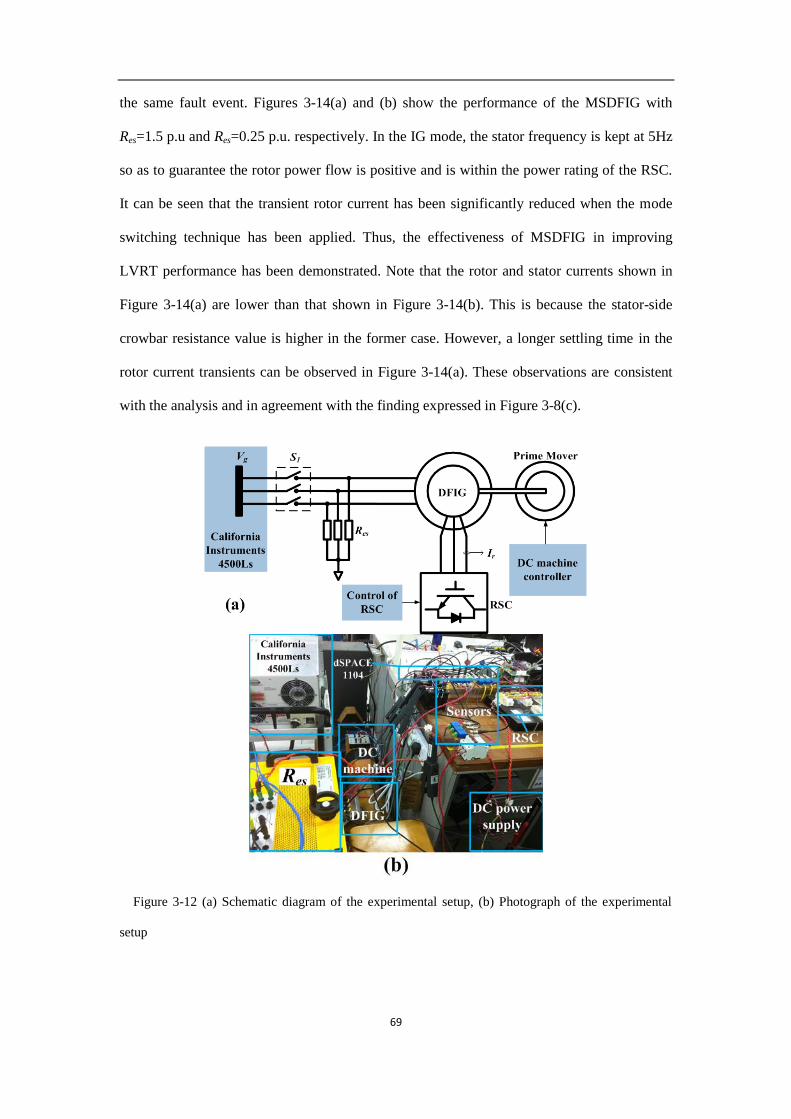
69
the same fault event. Figures 3-14(a) and (b) show the performance of the MSDFIG with
Res=1.5 p.u and Res=0.25 p.u. respectively. In the IG mode, the stator frequency is kept at 5Hz
so as to guarantee the rotor power flow is positive and is within the power rating of the RSC.
It can be seen that the transient rotor current has been significantly reduced when the mode
switching technique has been applied. Thus, the effectiveness of MSDFIG in improving
LVRT performance has been demonstrated. Note that the rotor and stator currents shown in
Figure 3-14(a) are lower than that shown in Figure 3-14(b). This is because the stator-side
crowbar resistance value is higher in the former case. However, a longer settling time in the
rotor current transients can be observed in Figure 3-14(a). These observations are consistent
with the analysis and in agreement with the finding expressed in Figure 3-8(c).
Figure 3-12 (a) Schematic diagram of the experimental setup, (b) Photograph of the experimental
setup

70
Figure 3-13 DFIG under three-phase 0.8 p.u. voltage sag: without mode switching
Figure 3-14 MSDFIG under three-phase 0.8 p.u. voltage sag: (a) Res=1.5 p.u.; (b) Res=0.25 p.u.

71
In conclusion, the effectiveness of the MSDFIG in mitigating the rotor-side overcurrent has
been clearly demonstrated by the laboratory measurements and theoretical analysis of the
effectiveness of the stator-side crowbar resistance has been validated.
3.6 Conclusion
The concept of MSDFIG is introduced and the DF and the IG modes of operation of
the DFIG are studied. Based on the equivalent circuits of the two modes, the transient
currents are evaluated when the DFIG switches from the DF to the IG and from the IG
back to the DF modes. A possible technique of using stator crowbar to reduce the
transient currents is proposed. The controllers of the GSC, RSC and crowbar in IG
mode of connection are also described. In the IG mode of connection, both the active
and reactive power flows through the back-to-back converters can be controlled and
in this manner, the converters can be prevented from over-loading. A suitable strategy
to adjust the stator crowbar resistance of the MSDFIG has been developed. A method
to re-synchronize and re-connect the DFIG to the grid has also been proposed. It is
shown that the method can effectively reduce the transient currents when the DFIG
reverts back to the DF mode from the IG mode. Simulation study shows the MSDFIG
is capable of riding through grid fault much more effectively and perform much better
than the conventional DFIG. Experimental results have also been included to verify
the effectiveness. However, there are potential shortcomings in the proposed LVRT
scheme and those can be summarized as follows. Firstly, in order to achieve improved
performance in an LVRT event, the resistor control of RCB needs to be performed
and it is found to be a complex issue. Secondly, the control mode switch shown in
Figure 3-5 gives rise to complications in the RSC controller.

72
Chapter 4. Mitigation of Unbalanced and Distorted
Stator Voltage of Stand-alone DFIGs Using
Repetitive Control
Unbalanced or non-linear loads result in distorted stator currents and
electromagnetic torque pulsations in stand-alone DFIGs. This thesis proposes the use
of a PIRC scheme to mitigate the levels of harmonics and unbalance at the stator
terminals of the DFIG. The PIRC is structurally simpler and requires much less
computation than existing methods. In this study, the PIRC is applied in time domain.
Analysis of the PIRC operation and the methodology to determine the control
parameters is included. Simulation study as well as laboratory test measurements
demonstrate clearly the effectiveness of the proposed PIRC control scheme.
4.1 Introduction
The research efforts on the renewable and clean energy generation systems are
receiving increasing attention globally. As one of the most attractive renewable
energy sources, wind energy is well known for its low cost, high energy density and
low pollution operational characteristics. Penetration of wind power world-wide is
expected to reach 20% by 2030 and it will continue to contribute to the global
electrical energy production in the future [1]. For the effective harnessing of wind
power, variable speed constant frequency generators are always favored and for which
DFIGs are used extensively in either stand-alone or grid-connected modes [1, 6, 14,
16-18, 25, 69-73]. As the power converters of the DFIG only handle part of the output
power [69] and are therefore of lower power rating, DFIGs are economically
73
attractive. Furthermore, DFIG enjoys higher efficiency because power loss in the
converters is smaller due to the lower power rating of the converters.
DFIGs operating under grid-connected mode have attracted the majority of research
interests so far. Issues related to low voltage ride through and active and reactive
power control are predominantly addressed in the literature [6]. However, power
systems in remote islands and rural areas require isolated generation systems to meet
the electricity demand. There are many examples where such isolated systems are
supplied by DFIG wind turbines [14, 16-18, 25, 69-71]. Furthermore, in the event of
grid fault, a small islanded system may be formed from the large grid following the
actions of protection scheme: thus, DFIG within the islanded system will need to
operate in the stand-alone mode [72]. The stand-alone generator systems will have to
operate with nonlinear and unbalanced loads connected to them. Such loads draw
distorted or unbalanced currents which will result in distorted and unbalanced
voltages at the stator terminals of the generators [73]. The negative phase sequence
component and harmonic components of the distorted stator voltage would induce
electromagnetic torque pulsations and excessive heat in the generators. Efficiency of
the generators will reduce and the performance of other loads will be affected.
Therefore, it is desirable to eliminate the negative phase sequence and harmonic
components of the stator voltage in order to overcome such deficiencies.
A common approach for harmonic elimination is to use RC method [19-23]. RC is a
technique based on the IMP [74] and is used specifically in tracking references or
rejecting disturbances which occur periodically. The repetitive controller presents
large gain at integral multiples of the fundamental frequency and is well known for its
effectiveness in controlling harmonics [20]. A hybrid scheme which combines PI and

74
RC techniques has been proposed in [19] in order to reduce the current harmonics of a
DC/AC inverter. However, it has yet to be extended for the case of stand-alone DFIGs.
In the present work, the proposed PIRC scheme is to eliminate the unbalanced and
harmonic components of the stator voltage of a stand-alone DFIG. In synchronous
reference frame, the fundamental components of the stator voltage are regulated by PI
controllers while the unbalanced and harmonic components are to be eliminated
through the application of RC technique. Compared to the control schemes described
in [6, 16, 17, 70, 75], the advantages of the proposed control strategy can be
summarized as follows:
• Both unbalanced and harmonic components can be eliminated by the same
proposed controller, unlike existing methods where the components have to be dealt
with separately. Thus, the proposed control scheme imposes much less computational
burden;
• Regardless of the reference frame, the proposed controller can effectively deal
with the periodic signals. This is unlike existing PI or PIR controllers in which the
control systems have to be changed when using different reference frames.
In Section 4.2, the modeling of stand-alone DFIGs and the impacts of harmonics
and unbalance stator voltage are explained. The proposed RC technique for harmonic
elimination is given in Section 4.3. This is followed in Section 4.4 by the frequency
response analysis of both steady and transient states of the proposed PIRC scheme.
Simulation and laboratory test results to validate the effectiveness of the scheme are
given in Sections 4.5 and 4.6 respectively.

75
4.2 Modeling and Control of Stand-alone DFIG
A typical configuration of stand-alone DFIG is shown in Figure 4-1 where loads,
including non-linear and unbalanced loads, are shown inter-connected to the stator
terminals of the DFIG. The rotor of the DFIG is interfaced through a back-to-back
converter scheme. Conventionally, the LSC controls the DC-link voltage and the RSC
controls the stator voltage.
4.2.1 Modeling of DFIG
The equivalent circuit of the DFIG in static stator-oriented reference frame is shown
in Figure 4-2 in which the rotor variables are referred to the stator side [76]. ,s sv , ,r sv
Figure 4-1 Typical configuration of stand-alone DFIG connected to nonlinear and unbalanced loads
Figure 4-2 Equivalent circuit of the DFIG in stator reference frame

76
, ,s si and ,r si represent the stator and rotor-side voltages and the stator and rotor
currents in the stator reference frame. Lls and Llr are the stator and rotor leakage
inductances. Lm is the magnetizing reactance. The dynamic behavior of the DFIG in
the synchronous rotating reference is described by the following equations:
s s s s sd
v R i jdt
(4-
1)
r r r sl rd
v R i jdt
(4-2)
and s rR R are very small compared with the leakage inductances and could be
ignored. and s r are the stator and rotor fluxes which can be determined using
s s s m rL i L i (4-3)
r r r m sL i L i (4-4)
where and s m ls r m lrL L L L L L . Ignoring the voltage drop across the stator
resistance and substituting (4-3) into (4-1), one can obtain the expression of stator
voltage as
s s s s m s rd d
v L j i L j idt dt
(4-5)
When the stator voltage is built up, the current is determined by the load conditions.
From (4-3) and (4-4), the stator and rotor fluxes can be expressed as

77
ms r s s
r
LL i
L
(4-6)
mr s r r
s
LL i
L
(4-7)
where 21 /m r sL L L . Substituting (4-7) into (4-2) one can obtain an expression
for the rotor voltage as
mr r r sl r sl s
s
Ld dv R L j i j
dt L dt
(4-8)
(4-1)-(4-8) constitute the DFIG model which will be discussed in Section 4.3.
4.2.2 Control of the Fundamental Component
The DC-link voltage of the DFIG system is controlled by the LSC while the rotor
current, transferred into the rotor reference frame, is regulated by the RSC. Magnitude
of the stator voltage sv is compared with its reference value and the error is inputted
to a PI controller to obtain the reference value of ir,q. The rotor current component
aligned in d-axis, denoted as ir,d, is regulated according to the d-axis stator current.
This is in order to force the fundamental reference frame to align itself with the vector
of stator flux [77]. Thus,
, ,s
r d s dm
Li i
L
(4-9)
The fundamental component control of stand-alone DFIG system is explained in
[78] and it is essential for the analysis of the controller in the following sections.

78
4.3 Co-ordinated control method development
4.3.1 Basic conception of RC
Periodic signals of period T can be generated by the system shown in Figure 2-17(a)
while the basic RC loop is shown in Figure 2-17(b). The transfer function of RC loop
is
1
sTrc fRC
RC sTRC
k G s QeO sG s
I s Qe
(4-10)
In general, zero steady-state error tracking of an external periodic input can be
achieved by incorporating the RC scheme into a closed-loop system [59].
4.3.2 PIRC for RSC
In addition to control action on the fundamental component which is discussed in
Section 4.1, the RC loop control is added to generate vr,d,rc and vr,q,rc that are
responsible for stator voltage harmonic and unbalance compensation as shown in
Figure 4-3.
As the DFIG is modeled using (4-1)-(4-8), in order to get the transfer function of
the RSC controller, the DFIG block shown in Figure 4-3 can be mathematically
represented by the DFIG model as shown in Figure 4-4 where Er,dq represent a
disturbance. In Figure 4-4, in order to simplify the analysis, only the inner loop
control is considered, i.e., only the rotor current control is analyzed in the fundamental
component control. This is reasonable because if the rotor current control is achieved,
the outer loop control which is discussed in Section 2.2.1 could also be obtained. In
the DFIG model, Ga and Gb are obtained using (4-5) while λs is derived using (4-3).
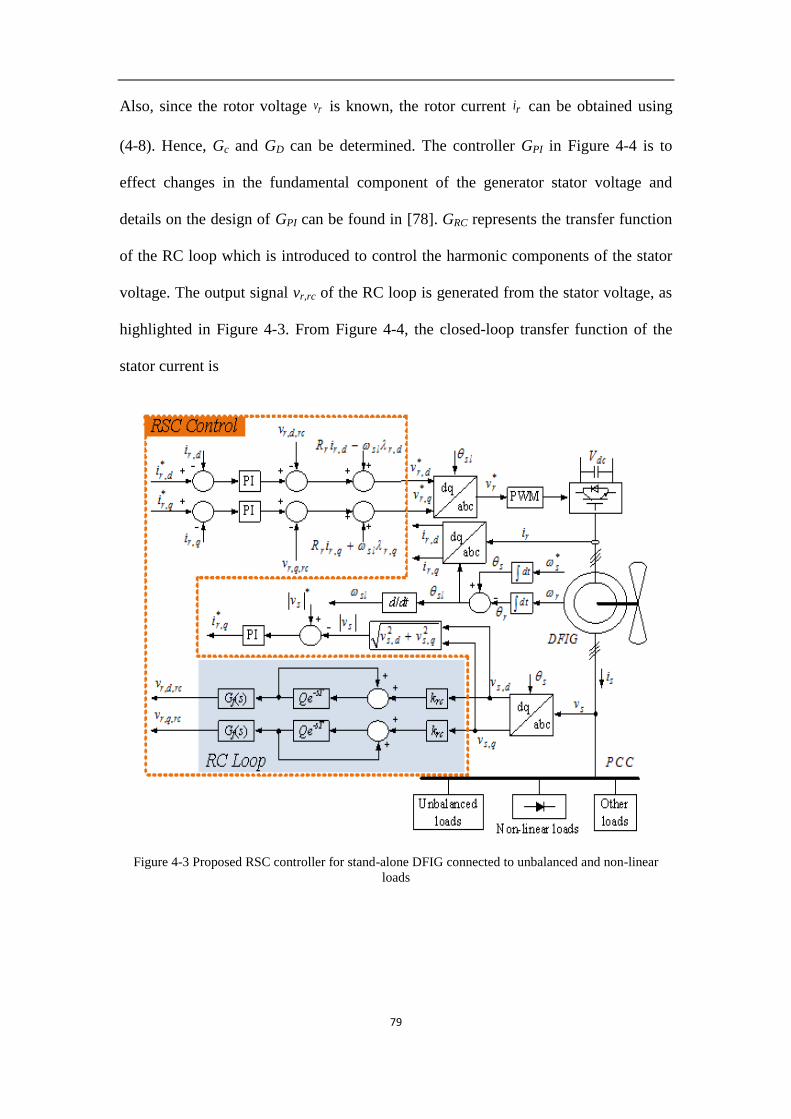
79
Also, since the rotor voltage rv is known, the rotor current ri can be obtained using
(4-8). Hence, Gc and GD can be determined. The controller GPI in Figure 4-4 is to
effect changes in the fundamental component of the generator stator voltage and
details on the design of GPI can be found in [78]. GRC represents the transfer function
of the RC loop which is introduced to control the harmonic components of the stator
voltage. The output signal vr,rc of the RC loop is generated from the stator voltage, as
highlighted in Figure 4-3. From Figure 4-4, the closed-loop transfer function of the
stator current is
Figure 4-3 Proposed RSC controller for stand-alone DFIG connected to unbalanced and non-linear
loads

80
Figure 4-4 Block diagram of stator voltage controller
*, 1 , 2 , 3 ,( ) ( ) ( )s dq r dq r dq s dqv s G i s G E s G i s
(4-11)
where G1, G2 and G3 represent the transfer functions from the reference rotor
current, rotor voltage disturbance and stator current to the stator voltage respectively.
Using Figure 4-4 and in the design of the stator voltage controller without the RC loop,
the stator voltage is given by
*, , ,
,
( ) ( )1 1
( )1
PI D a D as dq r dq r dq
m c D PI D m c D PI D
s c D ab s dq
m c D PI D
G G G G Gv s i s E s
L G G G G L G G G G
L G G GG i s
L G G G G
(4-12)
With the RC loop in the controller of RSC, from Figure 4-4, the transfer functions
pertaining to (4-11) can be expressed as
,1 *
,
1
( ) 1 1
sTPIs dq
sTr dq rc f
H s G s Qev sG
i s k G s H s Qe
(4-13)
,2
,
1
( ) 1 1
sTs dq
sTr dq rc f
H s Qev sG
E s k G s H s Qe
(4-

81
14)
,3
,
1
( ) 1 1
sTb s cs dq
sTs dq rc f
G H s L G Qev sG
i s k G s H s Qe
(4-15)
In (4-13)-(4-15), H s is
1
D a
m c D PI D
G GH s
L G G G G
(4-16)
Based on equations (4-12)-(4-16), an analysis to determine suitable control
parameters for the proposed control scheme for the RSC can be carried out, as follows.
4.4 Design of PIRC
The design of the PIRC is to meet the following requirements: the output ,s dqv s
needs to follow the rotor current reference; the harmonics and negative phase
sequence components of the stator voltage are to be minimized. In the following,
determination of the parametric values of the PIRC will be discussed with the view to
meet these requirements. In essence, the PI controller PIG s shown in Figure 4-4 is
designed first and from which, the determination of the parameters krc, Q and Gf of the
RC controller GRC are carried out in order to guarantee acceptable stability and
performance of the PIRC. This is detailed in Section 4.4.1. The steady-state analysis
given in Section 4.4.2 shows the effectiveness of PIRC. A general approach to design
the PIRC is illustrated in Section 4.4.3.
4.4.1 Stability Analysis
The performance and the determination of suitable parametric values for the PIRC

82
will be analyzed based on (4-12)-(4-15). Firstly the PI controller in Figure 4-4 would
be designed to achieve desired dynamic and steady state performance of the
conventional control system before the parameters of the RC loop are determined to
guarantee stability of the PIRC system. The characteristic equation of (4-12) is given
by
2s r s r s p sl s r s iD s L L s L R L k j L L s L k
(4-17)
The corresponding Routh table is shown in the Appendix 3-A and based on Routh-
Hurwitz stability criterion, when kp and ki are positive, stability of the stator voltage
control scheme will be guaranteed.
With stability of the system described by (4-12) guaranteed, then according to (4-
13)-(4-15) the PIRC system is stable if (4-18) is satisfied:
1 1 0, sTrc fk G s H s Qe s j
(4-18)
where 1.sT j Te e It can be readily shown that the condition (4-18) will be met
if
1
1 , 0,rc fk G j H jQ T
(4-19)
where 0, 1/ , .jfQ T f G j e f is the fundamental frequency and θ is the
compensation angle of RC loop.
Figure 4-5 provides a geometric explanation of (4-19) and can be used to help
determine .rck The condition (4-19) can be explained as the tip of the vector OK,
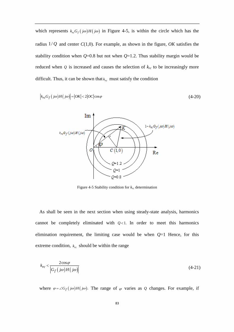
83
which represents rc fk G j H j in Figure 4-5, is within the circle which has the
radius 1/ Q and center C(1,0). For example, as shown in the figure, OK satisfies the
stability condition when Q=0.8 but not when Q=1.2. Thus stability margin would be
reduced when Q is increased and causes the selection of krc to be increasingly more
difficult. Thus, it can be shown that rck must satisfy the condition
2 cosrc fk G j H j OK OC (4-20)
Figure 4-5 Stability condition for krc determination
As shall be seen in the next section when using steady-state analysis, harmonics
cannot be completely eliminated with 1.Q In order to meet this harmonics
elimination requirement, the limiting case would be when Q=1 Hence, for this
extreme condition, rck should be within the range
2cosrc
f
kG j H j
(4-21)
where .fG j H j The range of varies as Q changes. For example, if

84
1, Q should satisfy the condition
,2 2
(4-22)
In examining (4-21), it is noted that H j has been determined during the design
of the PI controller PIG s , then, the lead compensator jfG j e
needs to be
designed to satisfy (4-22). fG j could be designed for 0 at the fundamental
frequency. Substituting s j into (4-16), one can obtain the value of
.fG j H j Using (4-21), the range of value for krc can be determined.
4.4.2 Steady-State Analysis
Next, the frequency response of the closed-loop control system of DFIG is
investigated, with the view to achieve zero steady-state harmonic levels. In the stand-
alone DFIG system, harmonics appear in the stator current si . Substituting ss n
1, 2,...n into (4-12), it is noted that , ,0 if 0.s dq s s dq sv n i n Furthermore,
the harmonics in the disturbance rE and harmonics in rotor current ri would also
distort the stator voltage. By substituting ss n 1, 2,...n into (4-15) and as
1,sjn Te
so when Q=1, the closed-loop transfer function G3 at the integer
multiples of the fundamental frequency is 0, i.e.
3( ) 0 1,2,ss jnG s n (4-23)
That is, with the RC loop incorporated in the RSC, (4-23) shows that the harmonic
components of the stator current which are integer multiples of the fundamental

85
Table 4-1 Parameters of DFIG for simulation and experimental test
Parameters Simulation Experiment
Rated power
f
Vrated
Vdc
Lm
1.5 MW
50 Hz
380 V
300 V
2.95 p.u.
1.5 kW
50Hz
220 V
160 V
1.2 p.u.
Ls 3.09 p.u. 1.25 p.u.
frequency will no longer distort the stator voltage.
Similarly, it is seen that G1 and G2 at ss n 1, 2,...n is also 0, i.e.
1( ) 0 1,2,ss jnG s n
(4-24)
2( ) 0 1,2,ss jnG s n
(4-25)
Again (4-24) and (4-25) show that the harmonic components of the reference rotor
current and disturbance signals in the rotor voltage, which are integer multiples of the
fundamental frequency, will not appear in the stator voltage.
As a result, harmonics in the stator voltage of the stand-alone DFIG shall be
effectively eliminated.
4.4.3 A General Approach to Design the PIRC
The analysis of Section 4.4.1 shows that kp and ki must be positive to guarantee
stability of the stator voltage control scheme at the fundamental frequency. The
general approach to the design of the complete PIRC can now be illustrated using the
example shown in Table 4-1. The parametric values shown there are quite
representative for a typical DFIG. Indeed, the simulation and experimental test results
shown in Sections 4.5 and 4.6 are based on the same DFIG parameters.
Accordingly and using these DFIG parameters, based on the analysis in Section
4.4.1 suppose the PIRC is designed to achieve an open-loop crossover frequency of

86
250Hz It results in kp=0.3, ki=10. Then based on (4-21), the gain of the RC is selected
to meet the condition krc<0.3.
krc decrease
Figure 4-6 Frequency response of (a) RC with variable krc at Q=1 and (b) RC with variable Q at krc=0.2,
(c) G1, (d) G2 and (e) G3 with and without RC loop
Figure 4-6 shows the Bode diagram of the RC controller as expressed by (4-10) for
a range of values of krc and Q. Figure 4-6(a) shows that the bandwidth of the
controller at each harmonic frequency is determined by krc: the bandwidth increases
with krc although it should concurrently satisfy (4-21). Figure 4-6(b) shows that the
87
gain of RC loop increases with Q. For example, at Q=1, RC has large gain at
harmonic frequencies but for Q=0.6, the gain decreases to -10dB. So in the following
analysis, krc=0.2 and Q=1 are selected. Most importantly, from Figure 4-6(a) and 4-
6(b), it is observed that when the parameters are properly selected, the RC presents
large gains at integer multiples of the fundamental frequency, which means that it is
possible for the proposed scheme to reject periodic harmonic components.
The frequency responses of G1, G2 and G3 are shown in Figure 4-6(c)-(e).
Compared with the conventional PI control, the PIRC controller can eliminate the
harmonics and unbalanced components because the frequency responses of G1, G2
and G3 equal to 0 at integer multiples of the fundamental frequency. It indicates that
with the PIRC, the harmonic components caused by rotor current, disturbance signals
and stator current can be mitigated.
4.5 Simulation results
A stand-alone DFIG with the parameters shown in Table 4-1 is modeled using
Matlab/Simulink. The proposed PIRC is applied in the RSC control. Various
conditions of non-linear and unbalanced load connected to the PCC are simulated. In
this study, the fundamental component of the stator voltage is controlled to be 0.8 p.u.
4.5.1 With non-linear load
A three-phase full-bridge diode rectifier with a resistive load is connected at the
PCC. As described in Section 4.2, the harmonics with 6n±1 multiples of fundamental
frequency would appear in both the stator current and voltage. The distorted stator
voltage can be mitigated using PIRC.

88
Figure 4-7 Simulation results: (a) rotor current, (b) magnitude of 5
th and 7
th harmonic components of
stator voltage (c) phase “a” stator voltage and (d) phase “a” stator current under nonlinear load
condition under conventional control and that under PIRC (All quantities are in p.u.), (e) FFT analysis
of stator voltage and (f) rotor current.
The performance of the PIRC applied in the stand-alone DFIG with a 0.8 p.u. rotor
speed is shown in Figure 4-7. In this figure, the first 0.1s is simulated with the
application of the conventional PI controller and the next 0.1s is with the PIRC. In
Figure 4-7(a), the rotor current is distorted when the conventional controller is applied
which verifies the analysis in Section 4.2. However, with the PIRC, the compensation
signal added in the rotor current leads to significant reduction in stator voltage
harmonic components as shown in Figure 4-7(b). The magnitudes of the 5th
and 7th
harmonic components are shown in Figure 4-7(b). In conventional controller, both the
5th
and 7th
harmonics are greaterthan 0.05p.u. and the THD is as large as 13%. With
the PIRC, the magnitudes of the 5th
and 7th
harmonics are reduced to around 0.02p.u.
while the THD is at a much lower value of some 3.5%. The waveform of phase “a”
stator voltage shown in Figure 4-7(c) reveals that distortion in the stator voltage has
been reduced with the use of the PIRC. The stator current is as shown in Figure 4-7(d).
The frequency spectrums of stator voltage and rotor current are shown in Figure 4-7(e)

89
and 4-7(f), respectively. According to Figure 4-7(e), it can be found that the harmonic
component in stator voltage is reduced significantly.
4.5.2 With unbalanced load
In this case, a three phase unbalanced resistive load is connected to the PCC, as a
consequence of which an unbalanced stator current is produced. It results in a
negative phase sequence component in the stator voltage.
Figure 4-8 Simulation results: (a) positive phase sequence component magnitude of vs, (b) negative
phase sequence component magnitude of vs, (c) three phase stator voltage and (d) phase “a” rotor
current under unbalanced load condition under conventional control and that under PIRC (All
quantities are in p.u.), (e) FFT analysis of rotor current.
The performance of the PIRC for unbalanced stator voltage compensation is shown
in Figure 4-8. The conventional controller is applied in the first 0.1s and the PIRC is
used in the next 0.3s. The magnitudes of the positive and negative phase sequence
components of the stator voltage are shown in Figure 4-8(a) and Figure 4-8(b),
respectively. The positive phase sequence component of the stator voltage is
maintained at around 0.8 p.u. in both the conventional controller and PIRC. The
negative phase sequence component is reduced from 0.13 p.u. when using the
90
conventional controller to less than 0.01 p.u. when PIRC is applied. The three phase
waveforms of the stator voltage are shown in Figure 4-8(c) and it shows that the
unbalanced stator voltage has been significantly reduced. The rotor current and its
frequency spectrum is shown in Figure 4-8(d) and 4-8(e), respectively. Similar to
Figure 4-7(a), the rotor current is distorted when conventional controller is used but
with the PIRC control, compensation component is added into the rotor current.
Based on the results of Figure 4-7(a) and Figure 4-8(d), it can be concluded that in
order to compensate for the 6n±1 order harmonics and unbalanced components,
compensation components of different frequencies need to be used.
4.6 Experimental results
To verify the effectiveness of the proposed PIRC technique, experimental
verifications are carried out with a 1.5 kW stand-alone DFIG. The experimental setup
of the system is shown in Figure 4-9. Both the PI and PIRC schemes are tested. In
order to simplify hardware requirements, the LSC assigned for DC-link voltage
control is replaced by a DC power supply with 160 V.dcV So in this study, only
RSC is controlled with the proposed controller as shown in Figure 4-3. The control
system is implemented on a platform consisting of dSPACE1104 microcontroller and
a programmable logic device. The switching frequency of RSC is kept at 5 kHz. The
nonlinear load is a full-bridge diode rectifier connected to a series-connected resistor-
inductor bank. The unbalanced load is implemented through manipulating a three-
phase adjustable resistance bank. The rotor speed is maintained at 0.8 p.u. In carrying
out the tests, firstly adjust the input DC voltage of a DC machine which is used as the
prime mover to achieve the rotor speed of 0.8 p.u. Then the PI or PIRC RSC
controller is switched on to maintain the stator voltage under different load conditions.

91
Figure 4-9 Experimental setup of a 1.5-kW stand-alone DFIG
4.6.1 With non-linear load
When the three-phase diode rectifier with resistive load is connected at the PCC,
the phase “a” stator voltage and rotor current are recorded. In this scenario, the
nonlinear load is a 50Ω resistor and a 20mH inductor connected with a diode rectifier.
See the results of Figure 4-10. When the DFIG is under conventional PI control, the
stator voltage in Figure 4-10(a) and the rotor current are seen to be highly distorted.
The stator voltage of the stand- alone DFIG under PIRC control is shown in Figure 4-
10(b). The harmonic components are significantly reduced while the fundamental

92
component is maintained constant. As the compensation signal is included, the rotor
current is distorted in the PIRC scheme.
4.6.2 With unbalanced load
When unbalanced loads are connected at the stator, the three phase stator voltage
and phase “a” rotor current are shown in Figure 4-11. Figure 4-11(a) shows the stator
voltage with one phase connected with a heavier load, i.e. the resistors at Phase A is
15Ω and at Phase B and C are both 50Ω. In this case, the stator voltage is unbalanced
and the rotor current is distorted. When the PIRC is applied, as shown in Figure 4-
Figure 4-10 Rotor current and stator voltage with (a) conventional controller and (b) PIRC with a non-linear
load connected at the PCC
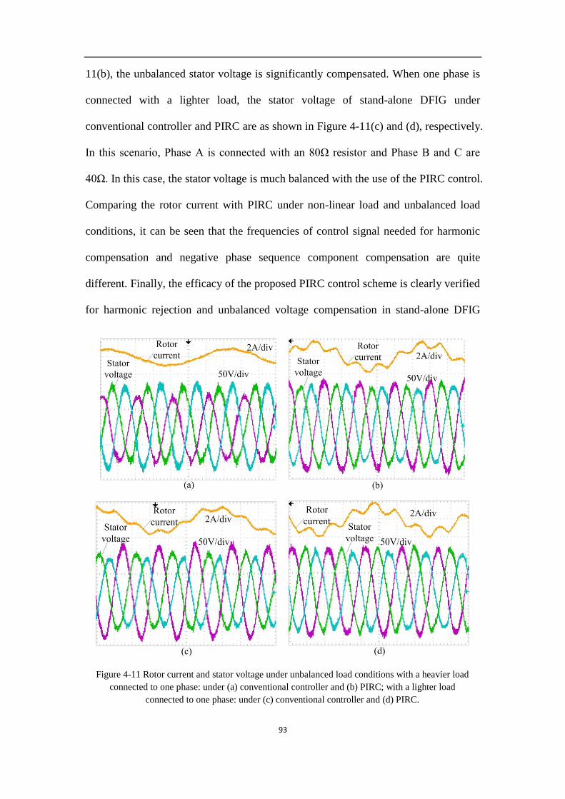
93
11(b), the unbalanced stator voltage is significantly compensated. When one phase is
connected with a lighter load, the stator voltage of stand-alone DFIG under
conventional controller and PIRC are as shown in Figure 4-11(c) and (d), respectively.
In this scenario, Phase A is connected with an 80Ω resistor and Phase B and C are
40Ω. In this case, the stator voltage is much balanced with the use of the PIRC control.
Comparing the rotor current with PIRC under non-linear load and unbalanced load
conditions, it can be seen that the frequencies of control signal needed for harmonic
compensation and negative phase sequence component compensation are quite
different. Finally, the efficacy of the proposed PIRC control scheme is clearly verified
for harmonic rejection and unbalanced voltage compensation in stand-alone DFIG
Figure 4-11 Rotor current and stator voltage under unbalanced load conditions with a heavier load
connected to one phase: under (a) conventional controller and (b) PIRC; with a lighter load
connected to one phase: under (c) conventional controller and (d) PIRC.

94
experimentally.
4.6.3 With combined non-linear and unbalanced loads
The experimental results under the combined non-linear and unbalanced loads
condition are shown in Figure 4-12. Figure 4-12(a) shows that the unbalanced and
harmonic components are present in the stator voltage with the conventional PI
controller. According to Figure 4-12(b), it can be readily seen that the negative phase
sequence and harmonic components are reduced when PIRC is applied in the RSC
controller. Therefore, it demonstrates clearly the PIRC is effective in providing both
unbalanced and distorted stator voltage compensation.
Figure 4-12 Rotor current and stator voltage with (a) conventional controller and (b) PIRC with
combined non-linear and unbalanced loads connected at the PCC
4.7 Conclusion
Stand-alone DFIGs are used in power generation in many situations. The stator
voltage of the DFIG may be distorted by non-linear or unbalanced loads. In order to
prevent such voltage distortions and hence reduce their negative impacts, PIRC is
proposed in this thesis for mitigating the levels of the voltage unbalance and
harmonics. The impact of these voltage components on the output performance of the

95
DFIG is also analyzed through transforming them into periodic components of
corresponding frequencies in the synchronous reference frame. The RC technique is
then employed to eliminate the periodic components. A single RC can compensate
both the harmonic and negative sequence components which are integer multiples of
the fundamental frequency and therefore, the controller is structurally simpler
compared to existing conventional control schemes which are developed in their
respective harmonic reference frames. The superior performance of the proposed
control scheme is verified by a series of simulation study and experimental tests.

96
Chapter 5. Power Quality Improvement of
DC-microgrid with DFIG Based Wind
Power Generation
A novel DFIG connection configuration is proposed in order to maintain the
advantages of DFIGs when they are connected to the DCMG. Accordingly, the
harmonic problem in the proposed configuration has been discussed. The harmonics
of stator current are eliminated by using RC in the RSC controller. A SC is proposed
to eliminate the harmonics in the stator power using repetitive control. The efficiency
of DFIG can be maintained at a higher value and the MPPT can still be achieved by
installing a battery energy storage system into each node. Furthermore, when the
BESS is fully charged or cut off due to fault conditions, the DFIG can be operated to
maintain the local voltage by switching the control mode of RSC so that the reliability
of the system can be increased.
DFIG is one of the most widely used wind power generators worldwide due to the
low cost and flexible controller. With the rapid development in DCMG, more and
more attention has been focused on the interconnection between DFIG and DCMG.
However, the DFIG will lose its benefits by using the conventional configuration.
Therefore, a novel configuration of DFIG is proposed in this thesis to solve this
problem. The harmonic problem has been solved and the efficiency of the generator
has been improved by the proposed techniques. Therefore, the proposed configuration
is realistic.

97
5.1 Introduction
Harmonics appear in both the stator current and stator power in the proposed DFIG
configuration because of SSR. Certain control methods for stator current harmonic
elimination of DFIG have been developed in [15, 32, 33, 77, 79-83]. In [80], to
eliminate the harmonic components, the corresponding commanded value of rotor
current is calculated using the parameters of the generator and the harmonic
components of the grid voltage. In this method, harmonics could be eliminated when
the rotor current tracks the commanded value but the performance of this controller is
limited by the speed of the controller and the accuracy of the commanded values. In
practice, the parameters of the generator may change in value due to operating
conditions and aging and it becomes difficult to achieve effective harmonic
elimination using this method. In [15, 32], the stator current harmonic components
extracted from BPF are transformed into DC values in the corresponding dq reference
frames and are controlled with the use of a PI controller. In this method, the harmonic
components in stator current could be eliminated but it requires a large number of
calculations because the controller of each order of harmonic component requires a
BPF, a dq frame transformation and a reverse dq frame transformation back to the
corresponding rotating frequency. The parameters of each PI control loop should be
determined carefully in order to guarantee the stability and dynamics of the control
system. Recently, PIR control technique has been proposed for harmonic elimination
of DFIG systems [33, 77]. The 5th and 7th harmonic components of stator current in
grid connected DFIGs [33, 82] and those of stator voltage in stand-alone DFIGs [77]
are eliminated by using a PIR controller. But the performance of this controller is
limited when some higher order harmonic components are contained in the stator
voltage. In order to overcome the shortages of the aforementioned methods, the

98
harmonic elimination of stator current is achieved by using RC in the RSC controller
in this chapter.
The harmonic elimination of output power of DFIG by control of RSC using PIR
control has been discussed in [80]. The shortages of PIR control have been discussed
as aforementioned and thus, RC will be applied in the controller. An additional super
capacitor is required to connect to the DFIG for purpose of stator power harmonic
elimination.
The efficiency of the generator is another concern when it is connected to the
DCMG. It is proposed in this chapter that a battery energy storage system (BESS) is
interfaced to the DCMG for the purpose of power buffering. In such a case, the grid
voltage can be maintained with the control of BESS and the DFIG would be able to
perform MPPT in order to achieve a greater efficiency.
In order to improve the reliability of the system, when the BESS is fully charged or
out of service due to fault conditions, the DFIG will be switched to a control mode
where the local DC voltage is regulated to achieve DC voltage droop control. With
this proposed control, the system can be kept stable even the BESS is out of service.
The organization of this chapter is as follows. In Section 5.2, the configuration of
the proposed DCMG connected with loads and distributed sources consisted by
BESSs and DFIGs is introduced. The harmonic problem in the stator current and
output power is discussed in Section 5.2 and 5.3, respectively and accordingly, a RC
technique of RSC and SC for harmonic elimination is proposed. The discussion on
control mode selection of control of RSC and BESS is given in Section 5.4.
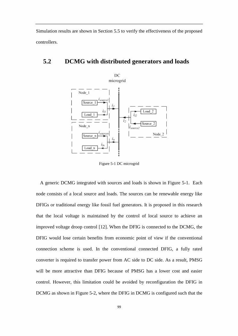
99
Simulation results are shown in Section 5.5 to verify the effectiveness of the proposed
controllers.
5.2 DCMG with distributed generators and loads
Figure 5-1 DC microgrid
A generic DCMG integrated with sources and loads is shown in Figure 5-1. Each
node consists of a local source and loads. The sources can be renewable energy like
DFIGs or traditional energy like fossil fuel generators. It is proposed in this research
that the local voltage is maintained by the control of local source to achieve an
improved voltage droop control [12]. When the DFIG is connected to the DCMG, the
DFIG would lose certain benefits from economic point of view if the conventional
connection scheme is used. In the conventional connected DFIG, a fully rated
converter is required to transfer power from AC side to DC side. As a result, PMSG
will be more attractive than DFIG because of PMSG has a lower cost and easier
control. However, this limitation could be avoided by reconfiguration the DFIG in
DCMG as shown in Figure 5-2, where the DFIG in DCMG is configured such that the
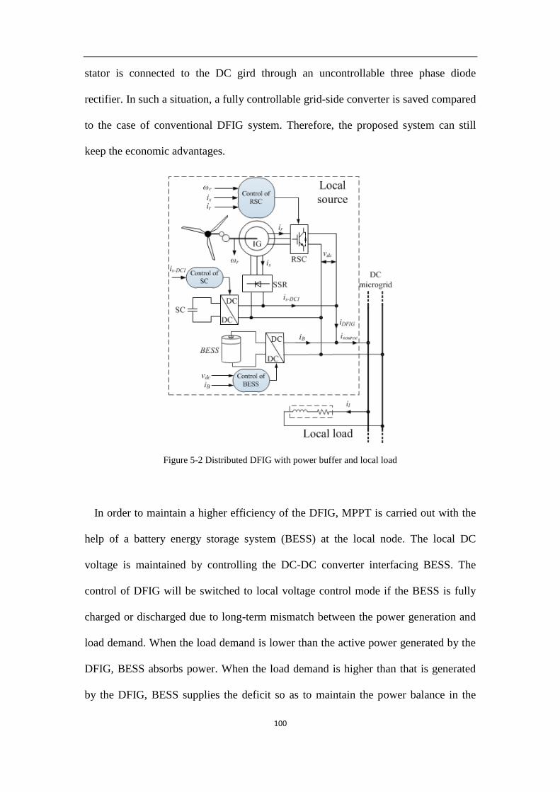
100
stator is connected to the DC gird through an uncontrollable three phase diode
rectifier. In such a situation, a fully controllable grid-side converter is saved compared
to the case of conventional DFIG system. Therefore, the proposed system can still
keep the economic advantages.
Figure 5-2 Distributed DFIG with power buffer and local load
In order to maintain a higher efficiency of the DFIG, MPPT is carried out with the
help of a battery energy storage system (BESS) at the local node. The local DC
voltage is maintained by controlling the DC-DC converter interfacing BESS. The
control of DFIG will be switched to local voltage control mode if the BESS is fully
charged or discharged due to long-term mismatch between the power generation and
load demand. When the load demand is lower than the active power generated by the
DFIG, BESS absorbs power. When the load demand is higher than that is generated
by the DFIG, BESS supplies the deficit so as to maintain the power balance in the

101
system. As a result, MPPT can be achieved and a higher power efficiency of the DFIG
can be maintained.
The details of each node are shown in Figure 5-2. In each node, the source consists
of a DFIG and a BESS. The stator of the DFIG is connected to the DCMG through a
stator-side rectifier (SSR).
Although the SSR could save the cost of the generation system, it leads to large
distortions in the stator voltage [34]. The harmonic components of stator voltage
would also cause harmonics in the stator current. The harmonic components are
harmful for the DFIG and they degrade its power efficiency. Therefore, a PI controller
with resonant loop (PIR) [34] is proposed to eliminate the stator current harmonics of
the DFIG in this configuration.
Due to distorted stator current, harmonic components would also appear at DC side
(is-DC). Although harmonics would be present at DC side of RSC (ir-DC), their
magnitude is smaller as rotor current is much smaller than the stator current.
Therefore, elimination of harmonics in is-DC has an enormous effect on the power
quality than the elimination of harmonics in ir-DC. In order to mitigate harmonics in is-
DC, a SC is connected to the DCMG through a DC-DC converter. The controller of the
DC-DC converter for harmonic elimination will be discussed in great detail in the
following sections.
In DCMG, changing load demand could sometimes cause power unbalanced.
Certain load demands lead to unbalanced load sharing among sources. When the
DFIG is controlled for MPPT, in some nodes with heavy loads, the BESS could be
fully discharged and the DC voltage cannot be maintained due to not sufficient power.
While in some nodes with very light loads or no loads, the BESS may be fully

102
charged and the output power of the source can become higher than the load demand
leading to an increased DC voltage. Thus, an improved droop control scheme for DC
voltage is proposed in this paper for the purpose of equitable load sharing and
maintaining the DC voltage.
5.3 Mitigation of Harmonics of stator current
5.3.1 Modeling of DFIG
The generator model in synchronous reference frame is given by
, , , ,s dq s s dq s s dq s dqd
v R i jdt
(5-1)
, , , ,r dq r r dq sl r dq r dqd
v R i jdt
(5-2)
The stator and rotor fluxes are defined as
, , ,s dq s s dq m r dqL i L i (5-3)
, , ,r dq r r dq m s dqL i L i (5-4)
The stator and rotor flux, stator current and rotor voltage can be calculated as
, , ,m
r dq s dq r r dqs
LL i
L
(5-5)
1ms r s
s s
Li i
L L
(5-6)
1s s
s
vs j
(5-7)

103
, ,m
r sl s dq r r sl r dqs
Lv s j R L s j i
L
(5-8)
The following analysis will be based on this model of DFIG.
5.3.2 Harmonic Problem of DFIG
As described in Section 5.1, the induction generator is connected to the DCMG
using a three-phase diode bridge rectifier. The details of SSR are shown in Figure 5-3.
The conduction sequence of the diodes is shown in Figure 5-4(a). Then, the phase to
phase voltages could be derived according to the order of diode conduction and are
shown in Figure 5-4(b). As the stator voltages are balanced, the phase voltages could
be derived and phase-a voltage is shown in Figure 5-4(c). It could be found that the
stator voltage is largely distorted. After Fourier series expansion, the stator voltage
can be expressed as shown in (5-9).
1
sin 2s n
n
v t a n ft
(5-9)
1 3 5
64 2
Vdc
Is
Vab
Va
DFIG
DC
microgrid
a
b
c
Figure 5-3 SSR of the DFIG

104
1
6
5
1
6
2
1
3
2
4
3
2
4
3
5
4
6
5
1
6
5
1
6
2
1
3
2
4
3
2
4
3
5
4
6
5
Vab
Vca
Vbc
Va
1
-1
1/32/3
Diode
Conduction
Sequence
0
0
(a)
(b)
(c)
Figure 5-4 (a) Diode conduction sequence, (b) waveform of stator phase to phase voltage, (c)
waveform of stator phase voltage
where an represents the amplitude of the nth
harmonic and n is the harmonic order. f
is the frequency of the fundamental component of stator voltage. The amplitude of
each order of harmonic could be calculated using
0
2 ( )sin 2 d ( 1, 2, )T
n sa f v t nft t n (5-
10)
where T=1/f. From (5-10), the following Fourier coefficients can be determined,
a1=0.6366, a5=0.1273, a7=0.0909, a11=0.0579, a13=0.0490, a17=0.0375 and
a19=0.0335. It is clear that the stator voltage not only contains the 5th
and 7th
harmonic
components, but also 11th
, 13th
, 17th
and 19th
harmonics as well. The magnitudes of
higher order harmonics are significant and cannot be ignored. Thus, the compensation
methods presented in [33, 77] that only focus on the 5th
and 7th
harmonic components
may not perform very well.

105
Pr
vs vr
Lm
RsPg Lls
Llr
im
ir
E1
E2=slE1
r rj
Rr
is
Figure 5-5 Equivalent circuit of the DFIG
The stator current would be distorted when stator voltage contains large amount of
harmonics. As shown in Figure 5-5, in steady state, when the voltage drop across the
stator resistor is ignored, the induced EMFs in the stator and rotor E1 and E2 are also
distorted. Thus, if the rotor-side injection voltage vr generated by rotor-side converter
is purely sinusoidal, the difference between distorted induced EMF in rotor E2 and
sinusoidal rotor voltage vr would lead to large harmonics in both rotor and stator
current. These harmonics would seriously deteriorate the power quality and the
efficiency of the DFIG. Therefore, the elimination of these harmonics is an essential
task for improving the efficiency of the DFIG. A strictly sinusoidal stator current
could ensure balanced heating and lower harmonic losses in the three-phase stator
windings.
Therefore, in order to guarantee the efficiency of the DFIG in the proposed
configuration, the harmonic components present in the stator current need to be
eliminated.
5.3.3 Harmonic Elimination Control Scheme
The control scheme with RC loops for the DFIG is shown in Figure 5-6, where krc is
the gain of RC, Gf(s) is a phase lead compensator and Q is a low-pass filter which
could set to be a constant [20]. The fundamental component control will be discussed
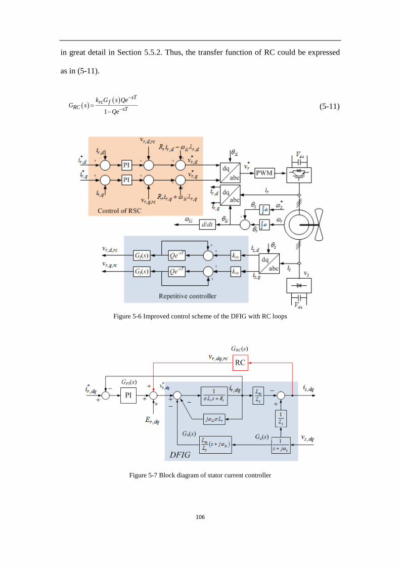
106
in great detail in Section 5.5.2. Thus, the transfer function of RC could be expressed
as in (5-11).
1
sTrc f
RC sT
k G s QeG s
Qe
(5-11)
Figure 5-6 Improved control scheme of the DFIG with RC loops
Figure 5-7 Block diagram of stator current controller

107
According to the IG model shown in (5-5)-(5-8), the schematic representation of the
current control loop of the DFIG is shown in Figure 5-7, where Er,dq is represented as
a disturbance. According to Figure 5-7, we denote GD(s)=1/(σLrs+Rr+jωslσLr),
GPI(s)=kp+ki/s, Ga(s)=1/(s+jωs), and Gb(s)= (s+jωsl)Lm/Ls. The closed-loop transfer
function of stator current is determined as
*, 1 , 2 , 3 ,( ) ( ) ( )s dq i r dq i r dq i s dqi s G i s G E s G v s
(5-12)
where Gi1, Gi2 and Gi3 are the transfer functions from commanded rotor current,
input rotor voltage disturbances and stator voltage to actual stator current respectively.
In conventional controller without the RC loop, the expression of stator current is
given in (5-13) with the help of Figure 5-7.
*, , , ,
1( ) ( ) ( )
1 1 1
m m mD PI D a b D
s s ss dq r dq r dq a s dq
D PI D PI D PI s
L L LG G G G G G
L L Li s i s E s G v s
G G G G G G L
(5-13)
With the RC loop, according to Figure 5-7, the transfer functions in (5-12) could be
expressed as
,1 *
,
1
( ) 1 1
sTPIs dq
i sTr dq rc f
H s G s Qei sG
i s k G s H s Qe
(5-14)
,2
,
1
( ) 1 1
sTs dq
i sTr dq rc f
H s Qei sG
E s k G s H s Qe
(5-15)
,3
,
/ 1
( ) 1 1
sTa b a ss dq
i sTs dq rc f
H s G G G L Qei sG
v s k G s H s Qe
(5-16)

108
where
1
m D
s D PI
L GH s
L G G
(5-17)
As the transfer function of the DFIG controlled with PIRC system is derived, the
performance and stability of the system will be analyzed in the following section.
5.3.4 The PIRC System Analysis
The stability analysis can be performed using the method introduced in Section
5.4.1. So that the stability margin of krc can be derived as
2cosrc
f
kG j H j
(5-18)
where fG j H j .
H(jω) is determined by the PI controller which should be first designed to achieve a
good performance of the fundamental component tracking.
The frequency response of the closed-loop system is investigated in order to
determine if the proposed controller guarantees a zero steady-state error.
For the DFIG connected DCMG system, the original harmonic components are
generated from the stator voltage vs. Substituting s=±nωs (n=1, 2,…) into the
conventional controller (5-13), it can be found that is,dq(nωs)≠0 if vs,dq(nωs)≠0. And it
means that the stator current would be distorted when harmonic components are
contained in the stator voltage.
Similarly, substituting s=±nωs (n=1, 2,…) into (5-16), when Q=1, it could be

109
observed that the frequency response of the closed-loop transfer function Gi3 at the
integral multiples of the fundamental frequency is equal to 0.
3( ) 0 1,2,si s jnG s n
(5-19)
It indicates that the harmonic components with integral multiples of the
fundamental frequencies in stator voltage will no longer distort the stator current in
the proposed controller. The frequency responses of Gi1 and Gi2 at resonant frequency
s=±nωs (n=1, 2,…) are also obtained as given by (5-20) and (5-21).
Figure 5-8 Frequency response of RC loop
Figure 5-9 Frequency response of (a) Gi1, (b) Gi2 and (c) Gi3 with and without PIRC
101
102
103
0
50
100
Frequency (Hz)
Magnitude (
dB
)

110
1( ) 0 1,2,si s jnG s n
(5-20)
2( ) 0 1,2,si s jnG s n
(5-21)
If the stator voltage is distorted, harmonic components would be present in rotor
current as well [19]. Thus, according to (5-20) and (5-21), the harmonic components
of rotor current and disturbance signals with integral multiples of the fundamental
frequency will not distort the stator current any more. And as a result, the harmonic
components in stator current could be effectively eliminated.
Figure 5-8 shows the Bode diagram of RC loop shown in (5-11) with Q=1 and
krc=0.5. The bandwidth of RC loop at each harmonic frequency is determined by krc
while the gain of RC loop is governed by Q. It could be found according to Figure 5-8
that the RC loop has large gain at each harmonic frequency and it can eliminate
multiple harmonics.
The frequency responses of Gi1, Gi2 and Gi3 are shown in Figure 5-9. It indicates
that with the conventional controller, Gi1, Gi2 and Gi3 cannot eliminate the harmonic
components but with PIRC, the effects of harmonic components in rotor current,
disturbance signals and stator voltage could be damped.
5.4 Harmonic elimination of the stator power
As the stator of the DFIG is connected to the DCMG using an SSR, the output
power of SSR could contain harmonics because of the uncontrollable rectifier. It is
proposed in Section 5.3 that stator current is compensated by applying PIRC in RSC.
However, the stator voltage is distorted. As a result, the output power of SSR contains
large amount of harmonics. To compensate harmonics in the SSR output power,

111
Figure 5-10 Control of SC
BESS is found to be not a suitable candidate, as high frequency power components
would be harmful for the batteries. Therefore, an SC interfaced with a DC-DC
converter is proposed in this section for the DFIG output power harmonic elimination
as shown in Figure 5-2. The most significant advantage SCs have over batteries is
their ability to be charged and discharged continuously without degrading like
batteries do. Therefore, SCs are more suitable for SSC output power harmonic
mitigation. The control scheme of SC is shown in Figure 5-10. The SC is controlled to
eliminate the harmonic components in s DCi to make the stator current flow to DCMG
1s DCi a pure DC value.
In the SC controller, a PI control loop is applied in the control of the DC component
and to keep the DC component of the current flow through SC to be zero. For
harmonic elimination of the output power of SSR, a RC scheme is applied in the SC
controller. As we assume the DC voltage of the DCMG is kept constant, s DCi is

112
linearly related to the output stator power. Thus, by eliminating the harmonic
components of s DCi we can also eliminate the harmonics in the output stator power.
For harmonic elimination, the RC is applied in the SC controller as mentioned
earlier. The RC scheme which presents large gains at the integral multiples of the
fundamental frequency is proposed to overcome aforementioned drawbacks in PI and
resonant controllers. The control scheme with RC loops of the DFIG is shown in
Figure 4-10, where rck is the gain for RC loop, fG s is a phase lead compensator
[19]. Thus, the transfer function of RC controller could be expressed as in (5-11).
In Figure 5-10, the output voltage of DC-DC converter is SCv , suppose the voltage
of DCMG is constant, so the current flow through the SC can be determined using
DC SCSC
v vi
sL
(5-22)
And the stator current flow of DFIG to the DCMG can be shown as follows.
1s DC s DC SCi i i (5-23)
In Figure 5-10, 1s DC hi is the harmonic component of the SSR current on DC side.
The transfer functions of 1s DC hi to harmonic reference of DCMG current *1s DC hi and
SSR current on DC side s DCi are given in (5-24)-(5-25), respectively.
1
1 *1 1 1
sTrc fs DC h RC
l sTlPI RCs DC h rc f
k G s H s ei GG
sL G Gi k G s H s e
(5-24)
12
1
1 1
sTlPI
s DC h lPIl sT
s DC lPI RC rc f
sL G s ei sL GG
i sL G G k G s H s e
(5-25)

113
In (5-24) and (5-25), GlPI is the transfer function of PI controller in Figure 5-10.
And
1
lPI
H sG s sL
(5-26)
Since , 1, 2,... 1sTse s n n , one can get
1 , 1, 2,... 1l sG s n n (5-27)
2 , 1, 2,... 0l sG s n n (5-28)
(5-27) shows that harmonic components with integral multiples of the fundamental
frequency of *1s DC hi can be tracked. (5-28) indicates that harmonic components of
s DCi can be eliminated. Therefore, the harmonic current flows to the DCMG from
SSR can be effectively mitigated.
5.5 Voltage control of DCMG
5.5.1 Voltage regulation by control of BESS
The improved droop control method [35] is applied in the voltage control of the
DCMG. The DC voltage of the microgrid is controlled by the local BESS. The control
scheme of BESS is shown in Figure 5-11. The total load demand will be measured by
the communications shown in Figure 5-11. The load sharing is decided by the
capacity of each source. An ideal equitable load sharing is to generate an equal
percentage of the rated power of each generator. In order to achieve an equitable load
sharing and stable DC grid voltage, the improved droop control technique is applied
in the control of BESS. Compared with the conventional droop control, the proposed
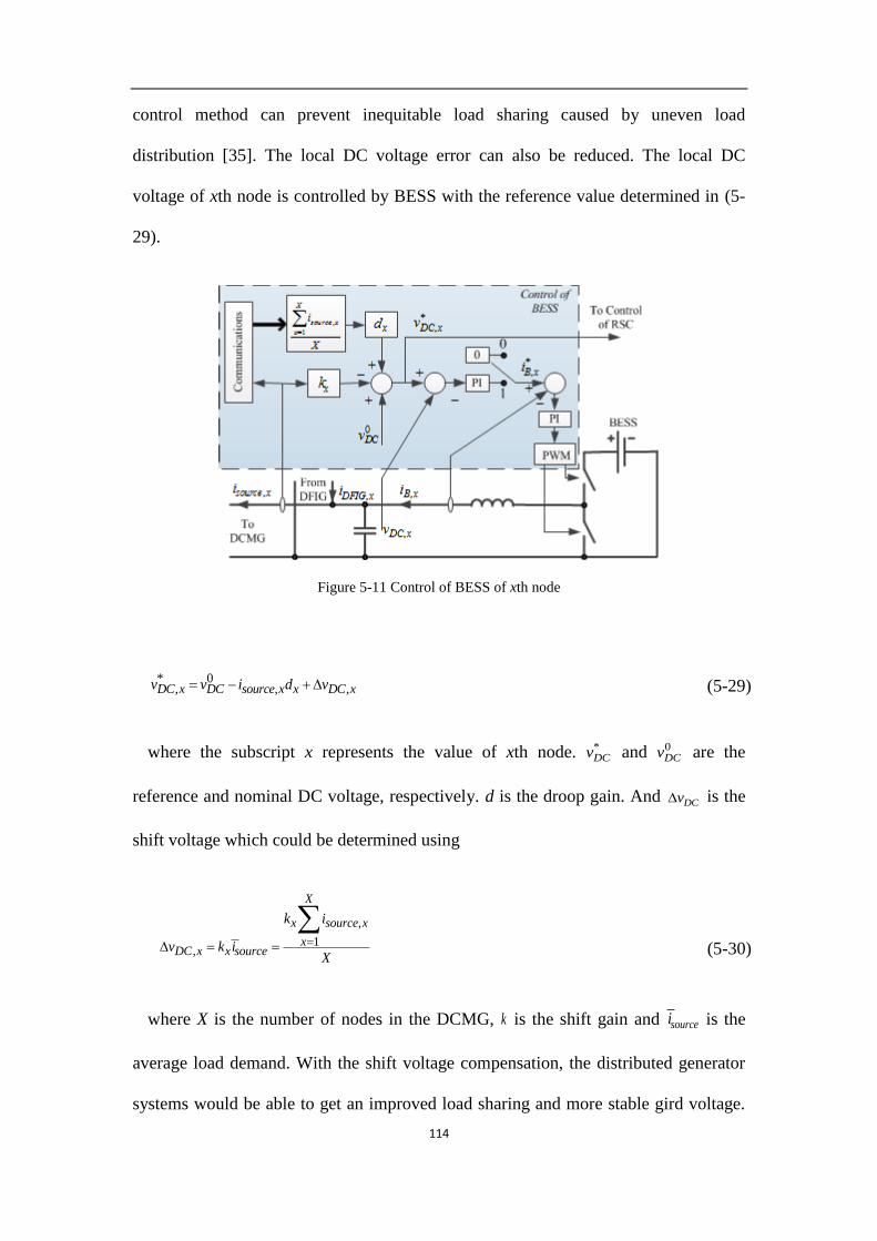
114
control method can prevent inequitable load sharing caused by uneven load
distribution [35]. The local DC voltage error can also be reduced. The local DC
voltage of xth node is controlled by BESS with the reference value determined in (5-
29).
Figure 5-11 Control of BESS of xth node
* 0, , ,DC x DC source x x DC xv v i d v (5-29)
where the subscript x represents the value of xth node. *DCv and 0
DCv are the
reference and nominal DC voltage, respectively. d is the droop gain. And DCv is the
shift voltage which could be determined using
,
1,
X
x source x
xDC x x source
k i
v k iX
(5-30)
where X is the number of nodes in the DCMG, k is the shift gain and sourcei is the
average load demand. With the shift voltage compensation, the distributed generator
systems would be able to get an improved load sharing and more stable gird voltage.

115
The droop and shift gains need to be determined carefully to guarantee the stability
and effectiveness of the controller and it has been discussed in [35].
In order to keep a high efficiency, the DFIG is controlled by RSC for MPPT in
normal conditions. Therefore the output active power of the DFIG varies with the
wind speed windv . However the capacity of the BESS is limited and the BESS can be
fully charged due to long time charging. Therefore, the control mode needs to be
changed due to different conditions. In mode 1, the BESS is controlled to regulate the
local DC voltage as aforementioned. In mode 0, the output current of BESS is
controlled to be zero. The mode selection will be discussed in the following sections.
5.5.2 Control of RSC
The control for RSC is given in Figure 5-12. In the DFIG control, the rotor current
component is aligned along d-axis, denoted as ,r di and is regulated using the d-axis
stator current. This is in order to force the fundamental reference frame to align itself
with the vector of stator flux [77]. Thus,
, ,s
r d s dm
Li i
L (5-31)
Therefore, the d-axis stator current is related to stator reactive power sQ . In the
proposed configuration, 0sQ . Therefore, *, 0s di .
In normal condition, ,r qi is controlled for MPPT as shown by mode 1 in Figure 5-12.
However when the BESS is fully charged or cut off, ,r qi is regulated for local DC
voltage control with the reference DC voltage given in (5-29), as shown by mode 0 in
Figure 5-12.

116
Figure 5-12 Voltage maintenance by control of RSC
5.5.3 Control mode selection
In order to improve the reliability of the system, different situations have been
considered and accordingly, different control modes have been selected. As
introduced previously, for control of BESS, mode 0 is to keep the output current of
BESS to be zero and mode 1 is to regulate the local DC voltage to get an equal load
sharing and stable DC voltage. For control of RSC, mode 0 is to obtain local DC
voltage droop control by regulating the output power of DFIG and mode 1 is to obtain
MPPT of DFIG.
In order to get a correct mode selection, the wind speed, state of charge (SOC) of
BESS and the average load demand need to be known. Once the wind speed is known,
the maximum output power can be determined using wind turbine characteristics
stored in a lookup table. The maximum output current of DFIG ,DFIG mi can be derived

117
Table 5-1 Mode selection of control of BESS and RSC
SOC of BESS Wind condition Control mode of
BESS Control mode of RSC
Fully charged ,DFIG m sourcei i 0 0
Fully charged ,DFIG m sourcei i 1 1
Normal NA 1 1
Fully discharged ,DFIG m sourcei i 1 1
Fully discharged ,DFIG m sourcei i 0 0
BESS fault NA Cut off 0
as the grid voltage is constant. Then the mode selection can be done based on Table 5-
1.
Table 5-1 shows that if the BESS is fully discharged and ,DFIG mi is smaller than
sourcei , the control of BESS and RSC is under mode 0. This situation should be avoided
by design because this situation means that the power supply is not sufficient for long
duration and some loads need to be cut off. If the BESS is fully charged and ,DFIG mi is
larger than sourcei , both the control of BESS and RSC should be under mode 0. In this
condition, the DFIG cannot supply sufficient power for maintaining the local voltage
thus the control of RSC should be under mode 1. If the BESS in out of service due to
reasons like fault in BESS, the DFIG is controlled in mode 0. Otherwise, control
mode 1 will be selected for control of both BESS and RSC.
5.6 Case study
In order to verify the effectiveness of the controllers, a simple DCMG system
combined with four nodes is simulated using Matlab/Simulink. The DCMG system is
shown in Figure 5-13. A local source consists of a DFIG and a BESS is connected at
each node. The parameters of the system are given in Table 5-2.

118
Table 5-2 Parameters of the system
Parameters Value
0DCv 250 V
linez 0.002 ,0.001H
Rated power of DFIG 7.5 kW
2,1li ,2,2li , 3li ,
4,1li ,4,2li 25A
Frequency of DFIG 50 Hz
Figure 5-13 Small DCMG for case study
5.6.1 Harmonic elimination of stator current
A. Simulation Results
A DFIG with rated power of 1.5 MW is modeled using Matlab/Simulink. The
parameters of the DFIG are shown in Table 4-1. Vrated is the stator side rated voltage.
Case 1: Without harmonic compensator
In the simulations carried out, the DFIG is under conventional control before 2.7s.
The waveforms of stator and rotor currents without harmonic compensator could be
found from 2.5s to 2.7s in Figures 5-14 to 5-16 when the rotor speed is 0.8, 1.0 and
1.2 p.u., respectively. It could be found that when DFIG is connected to the DCMG,
the stator current contains large harmonic components under conventional control in
different rotor speed scenarios.
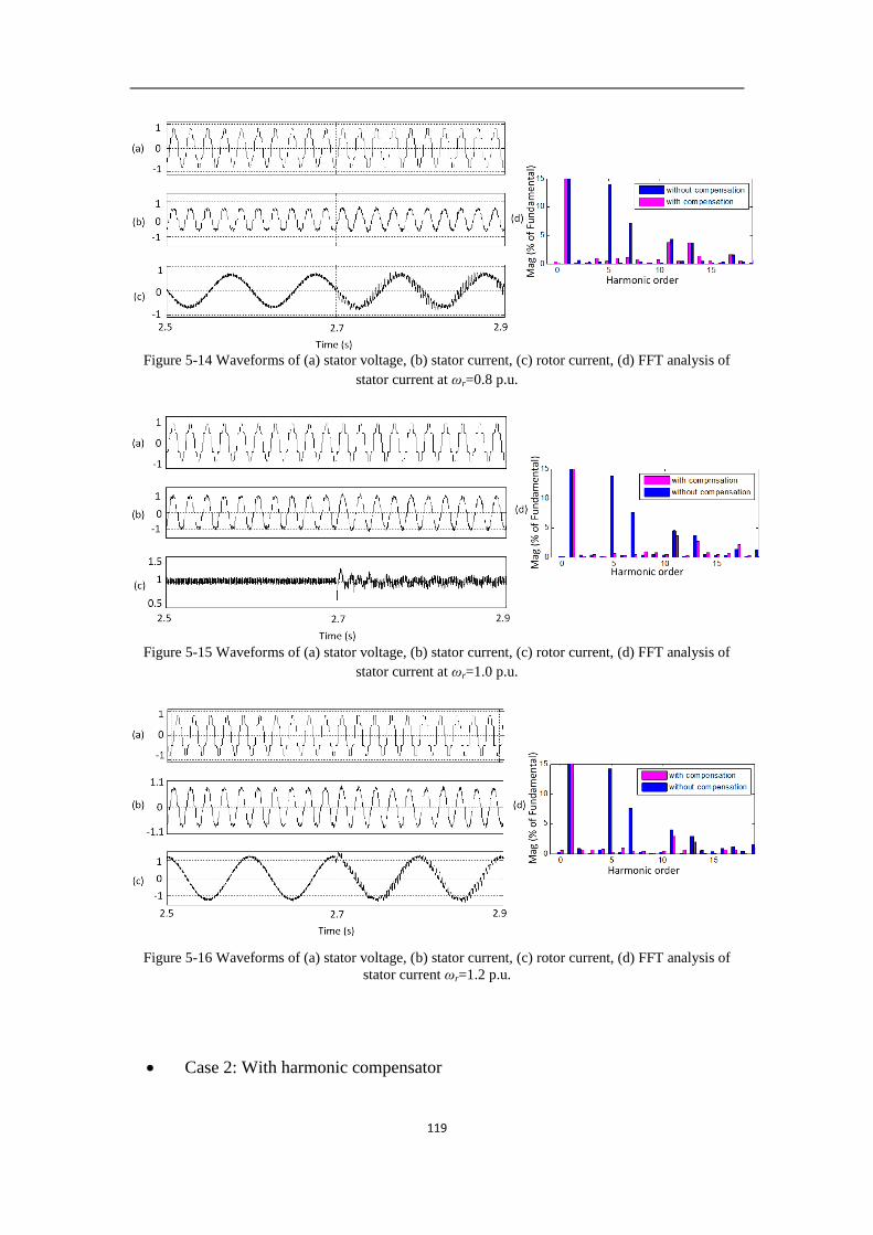
119
Figure 5-14 Waveforms of (a) stator voltage, (b) stator current, (c) rotor current, (d) FFT analysis of
stator current at ωr=0.8 p.u.
Figure 5-15 Waveforms of (a) stator voltage, (b) stator current, (c) rotor current, (d) FFT analysis of
stator current at ωr=1.0 p.u.
Figure 5-16 Waveforms of (a) stator voltage, (b) stator current, (c) rotor current, (d) FFT analysis of
stator current ωr=1.2 p.u.
Case 2: With harmonic compensator
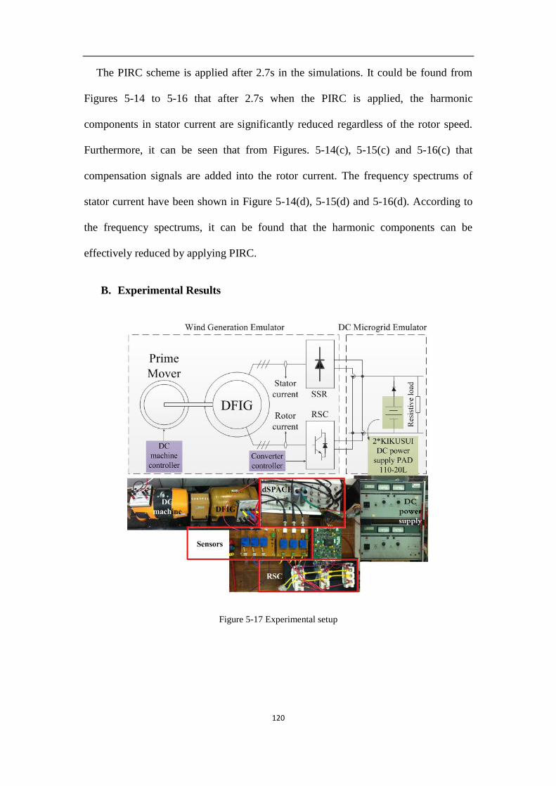
120
The PIRC scheme is applied after 2.7s in the simulations. It could be found from
Figures 5-14 to 5-16 that after 2.7s when the PIRC is applied, the harmonic
components in stator current are significantly reduced regardless of the rotor speed.
Furthermore, it can be seen that from Figures. 5-14(c), 5-15(c) and 5-16(c) that
compensation signals are added into the rotor current. The frequency spectrums of
stator current have been shown in Figure 5-14(d), 5-15(d) and 5-16(d). According to
the frequency spectrums, it can be found that the harmonic components can be
effectively reduced by applying PIRC.
B. Experimental Results
Figure 5-17 Experimental setup

121
50V
Stator voltage
Figure 5-18 Experimental waveform of the stator voltage
A DFIG system connected with a DC source is constructed for experimental
verification of the proposed methodology and the parameters of the system are listed
in Table 4-1. The block diagram of the experimental system is shown in Figure 5-17.
A DC machine is used to drive the rotor of the DFIG as a prime mover. The DC
machine is controlled in torque producing mode, which simulates the wind turbine
and gear box. The DCMG is emulated by two series connected DC sources. A
resistive load is connected to the DCMG to consume the active power generated by
the DFIG. The control system is implemented on a platform consisting of dSPACE
1104 and a programmable logical device.
Figure 5-18 shows the stator voltage of the DFIG. The stator voltage is distorted
and the waveform matches the aforementioned analysis.
Case 1: Without harmonic compensator
The stator and rotor currents under conventional control when the generator is in
sub-synchronous (ωr =0.8 p.u.), synchronous (ωr=1 p.u.) and super-synchronous (ωr
=1.2 p.u.) conditions are shown in Figures 5-19(a), 5-20(a) and 5-21(a), respectively.

122
Rotor current
Stator current 2A
Rotor current
Stator current
2A
(a) (b)
Figure 5-19 Experimental waveform of stator and rotor currents (a) without compensation, (b) with
compensation at ωr=1.0 p.u.
Rotor current
Stator current
2A
Rotor current
Stator current
2A
(a) (b)
Figure 5-20 Experimental waveform of stator and rotor currents (a) without compensation, (b) with
compensation at ωr=1.2 p.u
Rotor current
Stator current2ARotor current
Stator current
2A
(a) (b)
Figure 5-21 Experimental waveform of stator and rotor currents (a) without compensation, (b) with
compensation at ωr=0.8 p.u.
123
For the purpose of MPPT, the rotor speed of DFIG should be changed according to
the wind speed. This experimental result shows that without the harmonic
compensation control, large amount of harmonic components are present in the stator
current which would degrade the efficiency and lifetime of the generator. Moreover, it
can be found in the figures that the rotor current also contains harmonics even in the
conventional control conditions.
Case 2: With harmonic compensator
When PIRC is applied, the stator and rotor currents in different rotor speed
conditions are shown in Figures 5-19(b), 5-20(b) and 5-21(b), respectively. Compared
to Figures 5-19(a), 5-20(a) and 5-21(a), it could be found that the harmonic
components of stator current are largely mitigated although the harmonics in rotor
currents are not significantly increased. These experimental results verify that the
proposed controller could eliminate the harmonics of the stator current effectively and
the DFIG would be able to operate in DCMGs smoothly.
5.6.2 Harmonic elimination for the output power of DFIG
The effectiveness of control of SC is tested using simulation. Here it is assumed that
the control of BESS and RSC are both under mode 1. The DC voltage is maintained at
250V which is constant and the wind speed and load demand are constant as well. The
DFIG produces rated active power which is 7.5kW. The control of SC is shown in
Figure 5-10. The simulation results of DC side SSR current and current of SC are
shown in Figure 5-22. The control of SC starts working after 0.5s. Compared with the
1s DCi without compensation in the first 0.5s, 1s DCi with compensation contains 60%
less harmonic components. Therefore, the power quality of the DFIG can be

124
significantly increased by reducing the harmonics of 1s DCi . Moreover, it can be found
that the SC absorbs harmonics from 1s DCi and those harmonics are seen in SCi when
the compensation controller is applied.
FC current
Time (s)
0 0.5 1
iSC
is-DC1
0
0
10
10
-10
-20
20
20
30
40C
urr
ent
(A)
Cu
rren
t (A
)
Figure 5-22 Harmonic elimination of is-DC1
5.6.3 Load sharing under droop control with a step change load
The improved droop control is applied in the control of BESS in the DCMG system
at each node. The performance of the proposed control scheme shown in Figure 5-11
is tested under simulation. In the simulation, S1 is kept closed, S2 is closed at 1s and
open at 2s, S4 is closed at 4s. The DC voltage and source current at each node are
shown in Figure 5-23. The DC voltage waveforms show that the improved droop
control scheme can keep the system stable and maintain the DC voltage constant
during step load change conditions.
The step change of the source current at each node when S1 is closed is very similar
to that of S2. It means that the load location will not affect the equal load sharing in
improved droop control too much and the errors are within an acceptable range.

125
When S1 or S2 is closed, very little differences could be found in the source current
of each node. It indicates that the source location doesn’t affect the equal power
sharing too much as well. The simulation results verify that the improved droop
control could be applied in this system to guarantee the equal load sharing and
regulation of DC voltage.
260
250
240
260
250
240
260
250
240
260
250
240
0
10
20
30
0
10
20
30
0
10
20
30
0
10
20
30
0 1 2 3 4
Time (s)
vDC,1
isource,1
vDC,2
isource,2
isource,3
isource,4
vDC,3
vDC,4
A
A
A
A
V
V
V
V
S2 close S2 open S4 close
Figure 5-23 Local DC voltage and source current at each node with step change load

126
220
250
28015
25
35
45
-5-10
0
5
15
25
35
45
15
25
35
45
15
25
35
45
15
25
35
45
220
250
280
220
250
280
220
250
280
0 1 2 3
Time (s)
iB,1
iDFIG,1
isource,1
vDC,1
isource,2
isource,3
isource,4
vDC,2
vDC,3
vDC,4
S1 open
V
V
V
V
A
A
A
A
A
A
Figure 5-24 Local DC voltage and source current at each node when S1 is open
5.6.4 Voltage regulation when BESS is out of service
When the BESS is fully charged or out of service due to faults for example, the
control of RSC has to work in mode 0 to control the local DC voltage. Here suppose

127
the BESS at node 1 is cut off at 1s by opening S1, while S2 and S4 are kept open. The
current of DFIG in DC side, the current of BESS, the source current and DC voltage
at each node are shown in Figure 5-24. Before the BESS is cut off, both the control of
RSC and BESS are in mode 1 at each node. The DFIGs generate rated power before
1s which is larger than the load demand. Thus, the current of BESS is negative which
means the excess active power of the generator charges BESS. When the BESS is cut
off, iB,1 becomes zero and if the control of RSC is kept in mode 1, the local DC
voltage may increase due to the excess active power. According to Figure 5-24, it can
be found that when the BESS is cut off and the control of RSC is switched to mode 0,
iDFIG,1 decreases and equal to isource,1 to support the local DC voltage. And the
operation of the other nodes will not be affected. As a result, the reliability of the
DCMG system has been improved.
5.7 Conclusion
This chapter develops a novel connection scheme of DFIG connected in DCMG. In
the proposed connection, an SSR is connected between the stator and the grid in order
to reduce the cost of the DFIG. The harmonics in the stator current and output power
caused by SSR can be significantly reduced by applying RC scheme in the control of
RSC and SC so that the power quality of the system can be maintained. Moreover, in
order to maintain the high efficiency of the DFIG, the control of RSC is designed for
MPPT in normal operation and thus, the BESS is required to absorb or deliver active
power when the power of DFIG is larger or smaller than the load demand respectively.
For the purpose of increasing the reliability of the system, different modes of control
of RSC and BESS have been developed, so that when the BESS is out of work or
fully charged or discharged, the DFIG can be controlled for regulating the DC voltage

128
and the system can be kept stable. Finally, the effectiveness of the proposed
configuration and the corresponding controllers are verified by simulation results.

129
Chapter 6. Conclusion
6.1 Conclusion
This thesis concerns about the performance improvement of induction generator
systems in wind power generation. In Chapter 1, the background of the research work
and a brief introduction of the concerned issues are presented. The concerned issues
include low voltage ride-through problem, harmonic compensation problem and the
application in DC-microgrid of DFIG. The proposed solutions for such concerned
problems are discussed in great detail in Chapter 3-5, respectively.
In Section 2.1, a brief literature review on LVRT of DFIG is given. Based on which,
an improved MSDFIG is introduced for the purpose of improved LVRT in Chapter 3.
The DF and the IG modes of operation of the DFIG are studied. Based on the
equivalent circuits of the two modes, the transient currents when the DFIG switches
from the DF to the IG and from the IG back to the DF modes are evaluated. The
controllers of the GSC, RSC and crowbar in IG mode of connection are also described.
In the IG mode of connection, both the active and reactive powers through the back-
to-back converters can be controlled and in this manner, the converters can be
prevented from over-loading. A suitable strategy to adjust the stator crowbar
resistance of the MSDFIG has been developed. A method to re-synchronize and re-
connect the DFIG to the grid has also been proposed. It is shown that the method can
effectively reduce the transient currents when the DFIG reverts back to the DF mode
from the IG mode. Simulation study shows promising results because the MSDFIG is
demonstrated to be able to ride through grid fault much more effectively and perform
much better than the conventional DFIG.

130
In Section 2.2, the harmonic elimination methods using APF, PI and PIR control are
introduced. In order to keep the DFIG in low cost and improve the harmonic
elimination performance, the harmonic problem of stand-alone DFIG is discussed and
the RC is proposed for harmonic elimination of the stator voltage in Chapter 4. The
stator voltage of the stand-alone DFIG may be distorted by non-linear or unbalanced
loads. In order to prevent such voltage distortions and hence reduce their negative
impacts, PIRC is proposed in this chapter for mitigating the levels of the voltage
unbalance and harmonics. A single RC can compensate both the harmonic and
negative sequence components which are integer multiples of the fundamental
frequency, so the controller is structurally simpler compared to existing conventional
control schemes which are developed in their respective harmonic reference frames.
The superior performance of the proposed control scheme is verified by a series of
simulation study and experimental tests.
Based on the literature review on DCMG-connected DFIG given in Section 2.3, in
Chapter 5, a novel connection scheme of DFIG connected in DCMG is proposed. In
the proposed connection, an SSC is connected between the stator and the grid in order
to reduce the cost of the DFIG. The harmonics in the stator current and stator output
power caused by SSC could be significantly reduced by applying RC in the regulation
of RSC and SC respectively so that the power quality of the system can be improved.
Furthermore, in order to maintain the high efficiency of the DFIG, the control of RSC
is designed for MPPT in normal operation and thus, the BESS is required to absorb or
generate active power when the power of DFIG is larger or smaller than the load
demand. For the purpose of increasing the reliability of the system, different modes of
the control of RSC and BESS have been developed. Therefore, when the BESS is
fully charged or discharged, the DFIG can be controlled for the DC voltage regulation

131
and the system can be kept stable. Finally, the effectiveness of the proposed
configuration and the corresponding controllers are verified by simulation results.
6.2 Recommendations for Future Research
Notwithstanding of the above findings, the following areas are suggested for further
investigations. These unresolved challenges are briefly discussed here to provide
insights for future investigation. The potential research works will improve the
performance of the scheme(s) proposed.
Mitigation of unbalanced and distorted stator voltage of stand-alone DFIG using RC
is discussed in Chapter 4. RC is also applied in the stator current harmonic elimination
of DCMG connected DFIG which is discussed in Chapter 5. Compared with the PI
and PIR controller introduced in Section 2.2, RC technique for harmonic control is
found having a lower calculation burden and a better performance in dealing with
periodic signals. However, all the control methods dealing with harmonics are
frequency-sensitive. When the DFIG is connected to a large grid where the frequency
is considered to be constant, the harmonic elimination methods can achieve a great
performance in harmonic mitigation. But the stand-alone DFIG or DCMG-connected
DFIG of which the stator frequency is determined by the control of RSC, the stator
frequency could have a small shift when a sudden change happens in the load side or
generator side.
In PI or PIR control methods which are introduced in Section 2.2.3 and 2.2.4,
respectively, the angle of Park’s transformation will have an error if there is a
frequency shift in the stator side. Besides, the frequency shift gets deteriorated in the
harmonics because the error in the harmonic frequencies is multiples of that of the

132
fundamental component. Therefore, the harmonic components in their corresponding
reference frame will be no longer DC values and so that the PI and PIR controller will
lose the effectiveness in the harmonic mitigation. According to the frequency
response shown in Figure 4-9, the performance of PIRC will also be affected by
frequency shift.
To solve the frequency shift problem, it is essential to track the fundamental
frequency. Rather than using the fixed stator frequency, a possible solution for the
frequency shift problem is the use of frequency adaptive control technique combined
with the PIRC in the control of RSC. It is also presented by a few researchers [84, 85]
that the frequency shift can be avoided by applying the RC in frequency domain.
Therefore, the implementation of RC in frequency domain for DFIG harmonic
elimination can be carried out in the future work.
The DCMG-connected DFIG is investigated in Chapter 5. It is proved by simulation
and experimental results that the proposed control scheme of RSC can effectively
reduce the harmonics in the stator current. However, the stator voltage is still distorted
because of the use of SSR.
One possible path for stator voltage harmonic elimination is using a shunt
compensation connected between the stator wingdings and the SSR. In order to
improve the performance in harmonic elimination control, PIRC can be applied in the
control of shunt compensation device. In such a scenario, the stator voltage can be
purely sinusoidal while the cost of DFIG can be kept at a low value. However, the
power rating of the converter and the capacitor of the shunt compensation should be
carefully designed according to the magnitude of the harmonics.

133
The investigation on fault ride-through ability of the DCMG-connected DFIG is
another concern in the DCMG-connected DFIG. In the grid-connected DFIG, it is
required by the grid codes that the DFIG has to keep connected to the grid to generate
reactive power. The DFIG has to ride through grid fault conditions due to the grid
code requirement. However, as aforementioned, the fault ride through performance of
DFIG requires improvement because of the low power rating of the converters. There
are no such requirements for DCMG-connected DFIG because no reactive power is
required in the DCMG so that it is possible to achieve a significant improvement in
the performance of LVRT of the DCMG-connected DFIG. According to the
configuration of distributed DFIG with power buffer and local loads shown in Figure
5-2, a possible solution for LVRT of DCMG-connected DFIG is to isolate the local
sources and loads and design a stand-alone control scheme of the sources. Therefore,
the inrush current caused by the grid fault could be avoided and both the sources and
loads can ride through the grid fault smoothly. When the grid fault is cleared, it is
proposed to reconnect the sources to the DCMG to support the active power as soon
as possible. Therefore, the improvement of the fault ride through ability of the DFIG
in DCMG can be seen as an interesting topic for DFIG in future work.

134
Appendix 3-A
The derivation of the expressions for the transient current is shown as follows. The
following new symbols are defined:
2
; ; ; 1s mr rs r
s r s s r
L LL
R R L L
(A-1)
From (3-5), one can obtain the solution for the rotor current in the p domain as
,
3 2
1 1 1
1 1 1 1 1
s r sl m mr s s r
r dq
s sl s sl s sls r s r r s
j p V j L L pL L L
i p
p j p j j p
(A-2)
Then the poles of (A-2) can be derived
1,2 1,2
0 0
2 2
0
1 11 1 4 2 1
2 2 2
rs r r r r
r r
p
p j j
(A-3)
Thus, the expression of rotor current in time domain is as given in (3-6). The
constants in (3-6) are
, 0
, 0 1 2
,1 1 2 2
0
0
r dq
r dq
r dq
i C
i C C C
diC C
dt
(A-4)
where ,r dqi is the steady state value of the rotor current in the IG mode. It can be
derived using the following expressions

135
, ,
, ,
0s s s s dq s m r dq
r s r r r dq s r m s dq r
R j L i j L i
R j L i j L i v
(A-5)
and one can obtain
,
2
rr dq
s s s
s s s r s r r s s r m
Avi
B
A R j L
B R j L R j L L
(A-6)
, 0 /r dqdi dt is the initial differentiation value of rotor current and is governed by the
expressions
, ,
, ,
0 0 0
0 0
s s s s dq s m r dq
r s r r r dq s r m s dq r
d dR j L i j L i
dt dt
d dR j L i j L i v
dt dt
(A-7)
where
,, ,
0 1 10 0
r dq m r m s rr s dq r dq
r s r r r
di L Lv j i j i
dt L L L
(A-8)
Appendix 3-B
With given initial conditions of ωr, is and ir, the transient rotor current can be
readily determined by applying (3-7) – (3-10) to (3-6). In fact, once the initial steady-
state active power delivered to the grid Pd and the pf are known, then the initial
conditions can be derived as follows. The active power is given as
coss s sP V i (B-1)

136
where it is assumed 1 0sv , and θ is the angle between vs and is, Ps is the stator
active power. Ignore the copper loss in the generator, one obtains
(1 ) cosd s sl s sP P P s v i (B-2)
In (B-1), dP is the sum of stator and slip powers Ps and Psl.
Under normal steady state conditions, the rotor speed of wind generator is
controlled for MPPT. Take the GE 1.5 and 3.6 MW wind turbine-generators as
examples, the MPPT curve is given as [86],
20.67 1.42 0.51; 0 0.75
1.2; 0.75
d d dr
d
P P P
P
(B-3)
Then the initial stator current is
2; 0 0.75
0.67 1.42 0.51(0) cos
; 0.75 1.2
gg
g gs
gg
PP
P Pi
PP
(B-4)
The reactive power capability of each GE 1.5 MW machine is +0.95/-0.90 pf, while
for the 3.6 MW machine, it is +0.90/-0.90 pf [86]. With known pf, one can obtain the
stator current using
(0) (0) cos (0) sins s si i j i (B-5)
Whence the initial rotor current, rotor voltage are
(0) (0) sr s
m
vi i
jX (B-6)

137
Table 3A-I: Routh table of (3-17)
s rL L s iL k
s r s p sl s rL R L k j L L 0
s iL k 0
(0) (0) ( ) (0) ( )r s s s s m r r r mv sv si R j X X i R js X X (B-7)
Appendix 4-A
According to (4-17), the Routh table is given in Table 3A-I.
Whence, it can be established that if kp and ki are positive, the stability of the
transfer function in (4-17) can be guaranteed.

138
REFERENCES
[1] G. Pannell, D. J. Atkinson, and B. Zahawi, "Analytical Study of Grid-Fault
Response of Wind Turbine Doubly Fed Induction Generator," Energy
Conversion, IEEE Transactions on, vol. 25, pp. 1081-1091, 2010.
[2] M. Tsili and S. Papathanassiou, "A review of grid code technical requirements
for wind farms," Renewable Power Generation, IET, vol. 3, pp. 308-332, 2009.
[3] A. H. Kasem, E. F. El-Saadany, H. H. El-Tamaly, and M. A. A. Wahab, "An
improved fault ride-through strategy for doubly fed induction generator-based
wind turbines," Renewable Power Generation, IET, vol. 2, pp. 201-214, 2008.
[4] M. Mohseni, S. Islam, and M. A. S. Masoum, "Fault ride-through capability
enhancement of doubly-fed induction wind generators," Renewable Power
Generation, IET, vol. 5, pp. 368-376, 2011.
[5] S. Foster, L. Xu, and B. Fox, "Coordinated reactive power control for
facilitating fault ride through of doubly fed induction generator- and fixed
speed induction generator-based wind farms," Renewable Power Generation,
IET, vol. 4, pp. 128-138, 2010.
[6] M. Rahimi and M. Parniani, "Efficient control scheme of wind turbines with
doubly fed induction generators for low-voltage ride-through capability
enhancement," Renewable Power Generation, IET, vol. 4, pp. 242-252, 2010.
[7] S. Zhang, K. J. Tseng, S. S. Choi, N. Trong Duy, and D. L. Yao, "Advanced
Control of Series Voltage Compensation to Enhance Wind Turbine Ride
Through," Power Electronics, IEEE Transactions on, vol. 27, pp. 763-772,
2012.

139
[8] Y. Lihui, X. Zhao, J. Ostergaard, D. Zhao Yang, and W. Kit Po, "Advanced
Control Strategy of DFIG Wind Turbines for Power System Fault Ride
Through," Power Systems, IEEE Transactions on, vol. 27, pp. 713-722, 2012.
[9] D. Campos-Gaona, E. L. Moreno-Goytia, and O. Anaya-Lara, "Fault Ride-
Through Improvement of DFIG-WT by Integrating a Two-Degrees-of-
Freedom Internal Model Control," Industrial Electronics, IEEE Transactions
on, vol. 60, pp. 1133-1145, 2013.
[10] C. Wessels, F. Gebhardt, and F. W. Fuchs, "Fault Ride-Through of a DFIG
Wind Turbine Using a Dynamic Voltage Restorer During Symmetrical and
Asymmetrical Grid Faults," Power Electronics, IEEE Transactions on, vol. 26,
pp. 807-815, 2011.
[11] G. Wenyong, X. Liye, and D. Shaotao, "Enhancing Low-Voltage Ride-
Through Capability and Smoothing Output Power of DFIG With a
Superconducting Fault-Current Limiter–Magnetic Energy Storage
System," Energy Conversion, IEEE Transactions on, vol. 27, pp. 277-295,
2012.
[12] F. Wei and D. M. Vilathgamuwa, "Mode switching DFIG for low voltage ride
through," in Power Electronics and ECCE Asia (ICPE & ECCE), 2011 IEEE
8th International Conference on, 2011, pp. 2580-2587.
[13] A. K. Jain and V. T. Ranganathan, "Wound Rotor Induction Generator With
Sensorless Control and Integrated Active Filter for Feeding Nonlinear Loads
in a Stand-Alone Grid," Industrial Electronics, IEEE Transactions on, vol. 55,
pp. 218-228, 2008.

140
[14] R. Pena, R. Cardenas, E. Escobar, J. Clare, and P. Wheeler, "Control System
for Unbalanced Operation of Stand-Alone Doubly Fed Induction Generators,"
Energy Conversion, IEEE Transactions on, vol. 22, pp. 544-545, 2007.
[15] C. J. Ramos, A. P. Martins, and A. S. Carvalho, "Rotor Current Controller
with Voltage Harmonics Compensation for a DFIG Operating under
Unbalanced and Distorted Stator Voltage," in Industrial Electronics Society,
2007. IECON 2007. 33rd Annual Conference of the IEEE, 2007, pp. 1287-
1292.
[16] V. T. Phan and H. H. Lee, "Stationary frame control scheme for a stand-alone
doubly fed induction generator system with effective harmonic voltages
rejection," Electric Power Applications, IET, vol. 5, pp. 697-707, 2011.
[17] K. Vijayakumar, N. Kumaresan, and N. A. Gounden, "Operation and closed-
loop control of wind-driven stand-alone doubly fed induction enerators using a
single inverter-battery system," Electric Power Applications, IET, vol. 6, pp.
162-171, 2012.
[18] P. Van-Tung and L. Hong-Hee, "Performance Enhancement of Stand-Alone
DFIG Systems With Control of Rotor and Load Side Converters Using
Resonant Controllers," Industry Applications, IEEE Transactions on, vol. 48,
pp. 199-210, 2012.
[19] D. Sha, D. Wu, and X. Liao, "Analysis of a hybrid controlled three-phase grid-
connected inverter with harmonics compensation in synchronous reference
frame," Power Electronics, IET, vol. 4, pp. 743-751, 2011.
[20] Z. Bin, W. Danwei, Z. Keliang, and W. Yigang, "Linear Phase Lead
Compensation Repetitive Control of a CVCF PWM Inverter," Industrial
Electronics, IEEE Transactions on, vol. 55, pp. 1595-1602, 2008.
141
[21] C. Dong, Z. Junming, and Q. Zhaoming, "An Improved Repetitive Control
Scheme for Grid-Connected Inverter With Frequency-Adaptive Capability,"
Industrial Electronics, IEEE Transactions on, vol. 60, pp. 814-823, 2013.
[22] X. H. Wu, S. K. Panda, and J. X. Xu, "Design of a Plug-In Repetitive Control
Scheme for Eliminating Supply-Side Current Harmonics of Three-Phase
PWM Boost Rectifiers Under Generalized Supply Voltage Conditions," Power
Electronics, IEEE Transactions on, vol. 25, pp. 1800-1810, 2010.
[23] M. Nakano and S. Hara, Microprocessor-based repetitive control. Dordrecht:
Reidel Publ. Co., 1986.
[24] M. Shahabi, M. R. Haghifam, M. Mohamadian, and S. A. Nabavi-Niaki,
"Microgrid Dynamic Performance Improvement Using a Doubly Fed
Induction Wind Generator," Energy Conversion, IEEE Transactions on, vol.
24, pp. 137-145, 2009.
[25] C. Minyou, Y. Lei, N. S. Wade, L. Xiaoqin, L. Qing, and Y. Fan,
"Investigation on the Faulty State of DFIG in a Microgrid," Power Electronics,
IEEE Transactions on, vol. 26, pp. 1913-1919, 2011.
[26] W. Zhang, Y. Xu, W. Liu, F. Ferrese, and L. Liu, "Fully Distributed
Coordination of Multiple DFIGs in a Microgrid for Load Sharing," Smart Grid,
IEEE Transactions on, vol. PP, pp. 1-10, 2013.
[27] D. Pan, X. Kai-gui, Z. Li, and R. Xianliang, "Open-Switch Fault Diagnosis
and System Reconfiguration of Doubly fed Wind Power Converter Used in a
Microgrid," Power Electronics, IEEE Transactions on, vol. 26, pp. 816-821,
2011.

142
[28] M. Fazeli, G. M. Asher, C. Klumpner, and Y. Liangzhong, "Novel Integration
of DFIG-Based Wind Generators Within Microgrids," Energy Conversion,
IEEE Transactions on, vol. 26, pp. 840-850, 2011.
[29] S. Deshmukh, B. Natarajan, and A. Pahwa, "Voltage/VAR Control in
Distribution Networks via Reactive Power Injection Through Distributed
Generators," Smart Grid, IEEE Transactions on, vol. 3, pp. 1226-1234, 2012.
[30] C. Dong and X. Lie, "Autonomous DC Voltage Control of a DC Microgrid
With Multiple Slack Terminals," Power Systems, IEEE Transactions on, vol.
27, pp. 1897-1905, 2012.
[31] Y. K. Chen, Y. C. Wu, C. C. Song, and Y. S. Chen, "Design and
Implementation of Energy Management System With Fuzzy Control for DC
Microgrid Systems," Power Electronics, IEEE Transactions on, vol. 28, pp.
1563-1570, 2013.
[32] F. Lingling, S. Yuvarajan, and R. Kavasseri, "Harmonic Analysis of a DFIG
for a Wind Energy Conversion System," Energy Conversion, IEEE
Transactions on, vol. 25, pp. 181-190, 2010.
[33] L. Changjin, F. Blaabjerg, C. Wenjie, and X. Dehong, "Stator Current
Harmonic Control With Resonant Controller for Doubly Fed Induction
Generator," Power Electronics, IEEE Transactions on, vol. 27, pp. 3207-3220,
2012.
[34] F. Wei, D. M. Vilathgamuwa, and S. S. Choi, "Mitigation of harmonics of
DFIGs in DC-microgrids," in Energy Conversion Congress and Exposition
(ECCE), 2012 IEEE, 2012, pp. 1946-1953.
[35] S. Anand, B. G. Fernandes, and M. Guerrero, "Distributed Control to Ensure
Proportional Load Sharing and Improve Voltage Regulation in Low-Voltage

143
DC Microgrids," Power Electronics, IEEE Transactions on, vol. 28, pp. 1900-
1913, 2013.
[36] Y. Wang, D.-l. Zhao, B. Zhao, and H.-H. Xu, "A Review of Research Status
on LVRT Technology in Doubly-fed Wind Turbine Generator System," in
Electrical and Control Engineering (ICECE), 2010 International Conference
on, 2010, pp. 4948-4953.
[37] O. Anaya-Lara, L. Zifa, G. Quinonez-Varela, and J. R. McDonald, "Optimal
DFIG crowbar resistor design under different controllers during grid faults," in
Electric Utility Deregulation and Restructuring and Power Technologies,
2008. DRPT 2008. Third International Conference on, 2008, pp. 2580-2585.
[38] Z. Wei, Z. Peng, and H. Yikang, "Analysis of the by-pass resistance of an
active crowbar for doubly-fed induction generator based wind turbines under
grid faults," in Electrical Machines and Systems, 2008. ICEMS 2008.
International Conference on, 2008, pp. 2316-2321.
[39] P. Zhou and Y. He, "Control strategy of an active crowbar for DFIG based
wind turbine under grid voltage dips," in Electrical Machines and Systems,
2007. ICEMS. International Conference on, 2007, pp. 259-264.
[40] G. Wenzhong, W. Ge, and N. Jiaxin, "Development of low voltage ride-
through control strategy for wind power generation using real time digital
simulator," in Power Systems Conference and Exposition, 2009. PSCE '09.
IEEE/PES, 2009, pp. 1-6.
[41] S. Yang, Converter and Control for Doubly Fed Induction Generator-Based
Wind Power Generation. Heifei: HeFei University of Technology, 2007.

144
[42] V. Akhmatov, "An aggregated model of a large wind farm with variable-speed
wind turbines equipped with doubly-fed induction generators," Wind
Engineering, vol. 28, pp. 479-488, 2004.
[43] C. Abbey and G. Joos, "Supercapacitor Energy Storage for Wind Energy
Applications," Industry Applications, IEEE Transactions on, vol. 43, pp. 769-
776, 2007.
[44] M. Y. El-Sharkh, A. Rahman, M. S. Alam, and A. A. El-Keib, "Thermal
energy management of a CHP hybrid of wind and a grid-parallel PEM fuel cell
power plant," in Power Systems Conference and Exposition, 2009. PSCE '09.
IEEE/PES, 2009, pp. 1-6.
[45] A. Koyanagi, H. Nakamura, M. Kobayashi, Y. Suzuki, and R. Shimada,
"Study on maximum power point tracking of wind turbine generator using a
flywheel," in Power Conversion Conference, 2002. PCC-Osaka 2002.
Proceedings of the, 2002, pp. 322-327 vol.1.
[46] M. Ibrahim, A. Khairy, H. Hagras, and M. Zaher, "Using a fuzzy agent in
modeling lead-acid battery operating in grid connected wind energy
conversion systems," in Fuzzy Systems (FUZZ), 2010 IEEE International
Conference on, 2010, pp. 1-8.
[47] X. Y. Wang, D. Mahinda Vilathgamuwa, and S. S. Choi, "Determination of
Battery Storage Capacity in Energy Buffer for Wind Farm," Energy
Conversion, IEEE Transactions on, vol. 23, pp. 868-878, 2008.
[48] A. Petersson, "Analysis modeling and control of doubly-fed induction
generators for wind turbines," PhD, Chalmers University of Technology,
Sweden, 2005.
145
[49] P. S. Flannery and G. Venkataramanan, "A Fault Tolerant Doubly Fed
Induction Generator Wind Turbine Using a Parallel Grid Side Rectifier and
Series Grid Side Converter," Power Electronics, IEEE Transactions on, vol.
23, pp. 1126-1135, 2008.
[50] P. S. Flannery and G. Venkataramanan, "Evaluation of Voltage Sag Ride-
Through of a Doubly Fed Induction Generator Wind Turbine with Series Grid
Side Converter," in Power Electronics Specialists Conference, 2007. PESC
2007. IEEE, 2007, pp. 1839-1845.
[51] J. B. Ekanayake, L. Holdsworth, W. XueGuang, and N. Jenkins, "Dynamic
modeling of doubly fed induction generator wind turbines," Power Systems,
IEEE Transactions on, vol. 18, pp. 803-809, 2003.
[52] S. Muller, M. Deicke, and R. W. De Doncker, "Doubly fed induction
generator systems for wind turbines," Industry Applications Magazine, IEEE,
vol. 8, pp. 26-33, 2002.
[53] L. G. Meegahapola, T. Littler, and D. Flynn, "Decoupled-DFIG Fault Ride-
Through Strategy for Enhanced Stability Performance During Grid Faults,"
Sustainable Energy, IEEE Transactions on, vol. 1, pp. 152-162, 2010.
[54] H. Jiabing, X. Hailiang, and H. Yikang, "Coordinated Control of DFIG's RSC
and GSC Under Generalized Unbalanced and Distorted Grid Voltage
Conditions," Industrial Electronics, IEEE Transactions on, vol. 60, pp. 2808-
2819, 2013.
[55] N. P. Gupta, P. Gupta, and D. Masand, "Power quality improvement using
hybrid active power filter for a DFIG based wind energy conversion system,"
in Engineering (NUiCONE), 2012 Nirma University International Conference
on, 2012, pp. 1-6.

146
[56] R. K. M. P. Kazmierkowski, F. Blaabjerg and J. D. Irwin, Control in Power
Electronics: Selected Problems: Academic Press, 2002.
[57] T. Ying-Yu, S. L. Jung, and Y. Hsin-Chung, "Adaptive repetitive control of
PWM inverters for very low THD AC-voltage regulation with unknown
loads," Power Electronics, IEEE Transactions on, vol. 14, pp. 973-981, 1999.
[58] P. Roncero-Sanchez and E. Acha, "Dynamic Voltage Restorer Based on
Flying Capacitor Multilevel Converters Operated by Repetitive Control,"
Power Delivery, IEEE Transactions on, vol. 24, pp. 951-960, 2009.
[59] S. Chen, Y. M. Lai, S. C. Tan, and C. K. Tse, "Analysis and design of
repetitive controller for harmonic elimination in PWM voltage source inverter
systems," Power Electronics, IET, vol. 1, pp. 497-506, 2008.
[60] Z. Cao, X. Wang, and J. Tan, "Control strategy of large-scale DFIG-based
wind farm for power grid frequency regulation," in Control Conference (CCC),
2012 31st Chinese, 2012, pp. 6835-6840.
[61] X. Zhu, Y. Wang, L. Xu, X. Zhang, and H. Li, "Virtual inertia control of
DFIG-based wind turbines for dynamic grid frequency support," in Renewable
Power Generation (RPG 2011), IET Conference on, 2011, pp. 1-6.
[62] T. F. Wu, C. H. Chang, L. C. Lin, and Y. C. Chang, "DC-bus voltage control
for three-phase bi-directional inverter in DC microgrid applications," in
Applied Power Electronics Conference and Exposition (APEC), 2012 Twenty-
Seventh Annual IEEE, 2012, pp. 377-383.
[63] P. Sintupatsuk, S. Khomfoi, and P. Paisuwanna, "A dc to dc multilevel
modular capacitor clamped converter with electrical grounding isolation and
bidirectional power flow for a dc microgrid application," in Electrical
147
Engineering/Electronics, Computer, Telecommunications and Information
Technology (ECTI-CON), 2012 9th International Conference on, 2012, pp. 1-4.
[64] I. Syed and X. Weidong, "Modeling and control of DAB applied in a PV
based DC microgrid," in Power Electronics, Drives and Energy Systems
(PEDES), 2012 IEEE International Conference on, 2012, pp. 1-6.
[65] C. Yuan-Chih and L. Chang-Ming, "Establishment of a Switched-Reluctance
Generator-Based Common DC Microgrid System," Power Electronics, IEEE
Transactions on, vol. 26, pp. 2512-2527, 2011.
[66] H. Kakigano, Y. Miura, and T. Ise, "Low-Voltage Bipolar-Type DC Microgrid
for Super High Quality Distribution," Power Electronics, IEEE Transactions
on, vol. 25, pp. 3066-3075, 2010.
[67] S. M. Muyeen, R. Takahashi, T. Murata, and J. Tamura, "A Variable Speed
Wind Turbine Control Strategy to Meet Wind Farm Grid Code Requirements,"
Power Systems, IEEE Transactions on, vol. 25, pp. 331-340, 2010.
[68] C. Si Zhe, N. C. Cheung, W. Ka Chung, and W. Jie, "Grid Synchronization of
Doubly-fed Induction Generator Using Integral Variable Structure Control,"
Energy Conversion, IEEE Transactions on, vol. 24, pp. 875-883, 2009.
[69] S. Tao, C. Zhe, and F. Blaabjerg, "Flicker study on variable speed wind
turbines with doubly fed induction generators," Energy Conversion, IEEE
Transactions on, vol. 20, pp. 896-905, 2005.
[70] V. T. Phan and H. H. Lee, "Improved predictive current control for
unbalanced stand-alone doubly-fed induction generator-based wind power
systems," Electric Power Applications, IET, vol. 5, pp. 275-287, 2011.
148
[71] M. Tazil, V. Kumar, R. C. Bansal, S. Kong, Z. Y. Dong, W. Freitas, and H. D.
Mathur, "Three-phase doubly fed induction generators: an overview," Electric
Power Applications, IET, vol. 4, pp. 75-89, 2010.
[72] M. Aktarujjaman, M. A. Kashem, M. Negnevitsky, and G. Ledwich, "Control
Stabilisation of an Islanded System with DFIG Wind Turbine," in Power and
Energy Conference, 2006. PECon '06. IEEE International, 2006, pp. 312-317.
[73] M. P. Pattnaik and D. K. Kastha, "Adaptive Speed Observer for a Stand-Alone
Doubly Fed Induction Generator Feeding Nonlinear and Unbalanced Loads,"
Energy Conversion, IEEE Transactions on, vol. 27, pp. 1018-1026, 2012.
[74] F. B. A. a. W. W. M., The internal model principle for linear multivariable
regulators vol. 2: Appl. Math. Opt., 1975.
[75] J. Hu, Y. He, L. Xu, and B. W. Williams, "Improved Control of DFIG
Systems During Network Unbalance Using PI–R Current
Regulators," Industrial Electronics, IEEE Transactions on, vol. 56, pp. 439-
451, 2009.
[76] G. R. Slemon, "Modelling of induction machines for electric drives," Industry
Applications, IEEE Transactions on, vol. 25, pp. 1126-1131, 1989.
[77] P. Van-Tung and L. Hong-Hee, "Control Strategy for Harmonic Elimination in
Stand-Alone DFIG Applications With Nonlinear Loads," Power Electronics,
IEEE Transactions on, vol. 26, pp. 2662-2675, 2011.
[78] F. A. F. M. G. Simoes, Alternative Energy Systems: Design and Analysis with
Induction Generators 2nd ed. . Boca Raton: CRC Press, 2008.
[79] L. Yong, R. Li, G. A. Putrus, and K. S. Smith, "Evaluation of the effects of
rotor harmonics in a doubly-fed induction generator with harmonic induced

149
speed ripple," Energy Conversion, IEEE Transactions on, vol. 18, pp. 508-515,
2003.
[80] H. Jiabing, N. Heng, X. Hailiang, and H. Yikang, "Dynamic Modeling and
Improved Control of DFIG Under Distorted Grid Voltage Conditions," Energy
Conversion, IEEE Transactions on, vol. 26, pp. 163-175, 2011.
[81] B. Singh, G. K. Kasal, and S. Gairola, "Power Quality Improvement in
Conventional Electronic Load Controller for an Isolated Power Generation,"
Energy Conversion, IEEE Transactions on, vol. 23, pp. 764-773, 2008.
[82] A. E. Leon, J. M. Mauricio, and J. A. Solsona, "Fault Ride-Through
Enhancement of DFIG-Based Wind Generation Considering Unbalanced and
Distorted Conditions," Energy Conversion, IEEE Transactions on, vol. 27, pp.
775-783, 2012.
[83] H. Jiabing and H. Yikang, "Reinforced Control and Operation of DFIG-Based
Wind-Power-Generation System Under Unbalanced Grid Voltage
Conditions," Energy Conversion, IEEE Transactions on, vol. 24, pp. 905-915,
2009.
[84] W. Wei, S. K. Panda, and X. Jian-Xin, "Control of High Performance DC-AC
Inverters Using Frequency Domain Based Repetitive Control," in Power
Electronics and Drives Systems, 2005. PEDS 2005. International Conference
on, 2005, pp. 442-447.
[85] X. H. Wu, S. K. Panda, and J. X. Xu, "DC Link Voltage and Supply-Side
Current HarmonicsMinimization of Three Phase PWM BoostRectifiers Using
Frequency Domain BasedRepetitive Current Controllers," Power Electronics,
IEEE Transactions on, vol. 23, pp. 1987-1997, 2008.

150
[86] N. W. Miller., W. W. Price., and J. J. Sanchez-Gasca., "Dynamic Modeling of
GE 1.5 and 3.6 Wind Turbine-Generators," 2003.

151
Publications
Conference papers
[1] F. Wei and D. M. Vilathgamuwa, "Mode switching DFIG for low voltage ride
through," in Power Electronics and ECCE Asia (ICPE & ECCE), 2011 IEEE 8th
International Conference on, 2011, pp. 2580-2587.
[2] F. Wei, D. M. Vilathgamuwa, and S. S. Choi, "Mitigation of harmonics of DFIGs
in DC-microgrids," in Energy Conversion Congress and Exposition (ECCE), 2012
IEEE, 2012, pp. 1946-1953.
[3] F. Wei, D. M. Vilathgamuwa, S. S. Choi, and Z. Xinan, "Improved control of
rotor- and load-side converters of stand-alone DFIGs under nonlinear loads
conditions," in ECCE Asia Downunder (ECCE Asia), 2013 IEEE, 2013, pp. 687-691.
Journal papers
[1] F. Wei, Z. Xinan, D. M. Vilathgamuwa, S. S. Choi, and W. Shuai, "Mitigation of
distorted and unbalanced stator voltage of stand-alone doubly fed induction generators
using repetitive control technique," Electric Power Applications, IET, vol. 7, pp. 654-
663, 2013.
[2] F. Wei, D. M. Vilathgamuwa and S. S. Choi, "Design of mode swicthing scheme
for low voltage ride through of doubly-fed induction generators," Renewable Power
Generation, IET, vol. 8, 2014.
Top Related