


Languages
Pages
Legal

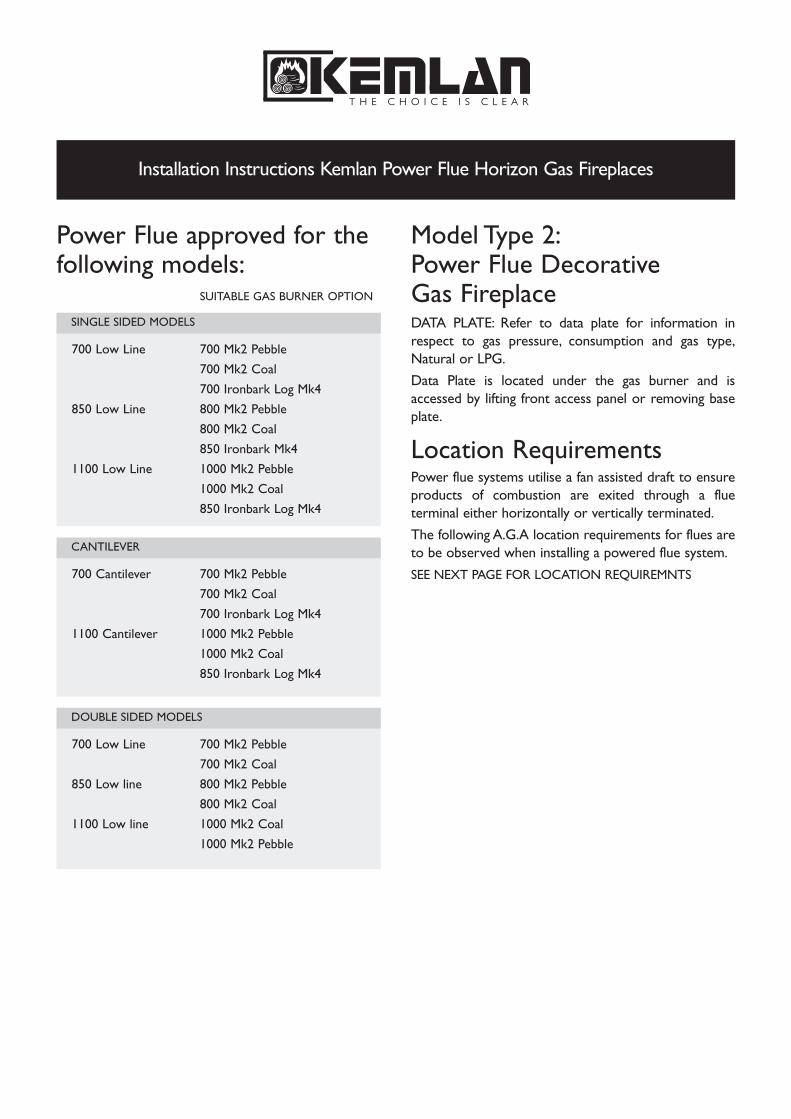
Power Flue approved for thefollowing models:
SUITABLE GAS BURNER OPTION
700 Low Line 700 Mk2 Pebble
700 Mk2 Coal
700 Ironbark Log Mk4
850 Low Line 800 Mk2 Pebble
800 Mk2 Coal
850 Ironbark Mk4
1100 Low Line 1000 Mk2 Pebble
1000 Mk2 Coal
850 Ironbark Log Mk4
700 Cantilever 700 Mk2 Pebble
700 Mk2 Coal
700 Ironbark Log Mk4
1100 Cantilever 1000 Mk2 Pebble
1000 Mk2 Coal
850 Ironbark Log Mk4
700 Low Line 700 Mk2 Pebble
700 Mk2 Coal
850 Low line 800 Mk2 Pebble
800 Mk2 Coal
1100 Low line 1000 Mk2 Coal
1000 Mk2 Pebble
Model Type 2: Power Flue Decorative Gas FireplaceDATA PLATE: Refer to data plate for information inrespect to gas pressure, consumption and gas type,Natural or LPG.
Data Plate is located under the gas burner and isaccessed by lifting front access panel or removing baseplate.
Location RequirementsPower flue systems utilise a fan assisted draft to ensureproducts of combustion are exited through a flueterminal either horizontally or vertically terminated.
The following A.G.A location requirements for flues areto be observed when installing a powered flue system.
SEE NEXT PAGE FOR LOCATION REQUIREMNTS
DOUBLE SIDED MODELS
CANTILEVER
SINGLE SIDED MODELS
Installation Instructions Kemlan Power Flue Horizon Gas Fireplaces

Installation Instructions Kemlan Power Flue Horizon Gas Fireplaces
NOTES: 1. All distances are measured vertically or horizontally along the wall to a pointin line with the nearest part of the terminal.
2. Prohibited area below electricity meter or fuse box extends to ground level.3. See clause 5.13.6.6 for restrictions on a flue terminal under a roofed area.4. See Appendix J, Figure J1(a) and J2(a) for clearances required from a flue
terminal to a LP Gas cylinder. A flue terminal is considered to be a source of ignition.
MINIMUM CLEARANCES REQUIRED FOR BALANCED FLUE TERMINALSOR THE FLUE TERMINALS OF OUTDOOR APPLIANCES
CLEARANCES ‘n’ (mm)
Space heaters All other appliances
Up to 50 MJ/hinput
UP to 50 MJ/hinput
Over 50 MJ/h &up
to 150 MJ/h
Over 150 MJ/hinput
150 500 1000 1500
a - Below eaves, balconies or other projections: MIN. CLEARANCE (mm)Appliances up to 50 MJ/h input ........................................................................................................................ 300Appliances over 50 MJ/h input .......................................................................................................................... 500
b - From the ground or above a balcony .................................................................................................................. 300c - From a return wall or external corner ................................................................................................................. 500d - From a gas meter (M) ............................................................................................................................................. 1000e - From an electricity meter or fuse box (P) .......................................................................................................... 500f - From a drain or soil pipe .......................................................................................................................................... 150g - Horizontally from any building structure (unless appliance approved
for closer installation) or obstruction facing a terminal ................................................................................. 500h - From any other flue terminal, cowl, or combustion air intake ..................................................................... 500j - Horizontally from an openable window, door, non-mechanical air
inlet, or any other opening into a building, with the exception ofsub-floor ventilation:
Appliances up to 150 MJ/h input ....................................................................................................................... 500Appliances over 150 MJ/h input ....................................................................................................................... 1500
...................................................................................... 1500k - From a mechanical air inlet, including a spa blowern - Vertically below an openable window, non-mechanical air inlet
or any other opening into a building, with the exception of sub-floor ventilation ........... See table below
Shading indicates prohibitedretem saG = Mlanimret eulF = TI = Mechanical air inlet P = Electricity meter or fuse box areas for flue terminals
Location Requirements

Installation Instructions Kemlan Power Flue Horizon Gas Fireplaces
Before InstallationThe Horizon powered flue system shall be installed byauthorized personnel in accordance with themanufacturer’s installation instructions, local gas fittingregulations, municipal building codes, electrical wiringregulations, and any other statutory regulations. Contactyour local building authorities about restrictions andinstallation inspections that may be required. If in doubtcontact your local dealer or Kemlan’s Head office.
IMPORTANT AUSTRALIAN CODES:
• Australian Standards AS 5601 Gas Installation• Australian Standards AS 3000 Electrical
Important Safety Notes• Comply with all instructions in manual including
clearances to combustible material.
• Do not operate without fully assembling all components.
• All open gas fires require ventilation in the room.
• Do not connect to any other air distribution duct or system.
• When using an internal fan system an A.G.A approved cowl is required at flue terminal.
• Air movement of systems- A decorative gas log fire must not be installed where the operation of any ventilation system, fan or air blower could in any circumstances cause the air pressure to be less than atmospheric at the appliance.
• Do not block or restrict chimney. The power flue system operates on pressure switches opening a valve for gas to flow. If flue is blocked the system will cut out.
• After installing appliance check that the flue drawswell with smoke pellet.
• Kemlan recommends that all gas fires be serviced every year.
• All gas units must be fitted by a licensed gas fitter.
• It is the responsibility of the gas fitter to follow the regulations set out in the Gas Code that dictate the procedures to follow when installing a gas appliance, particularly regarding gas pipe sizing and checking of pressures. (see page 10)
Installation1 Access must always be available to the fan system for
servicing. If installing the internal fan system an access panel of 400mm x 400mm needs to be installed with a clearance of 100mm over the top of fan to lift out.
2 The power flue Horizon system is supplied with all required electrical fittings. Work needs to be undertaken by a licensed electrician if extending wiring. Wiring requires clearance of minimum 100mm to flues and fireplace body due to heat. See Wiring diagram page. Wiring must be positivelysecured away from heat source.
3 An isolation switch needs to be provided if connecting within fireplace framework.
4 Build frame to specifications provided.
5 Unit located on 10mm fiber cement sheeting. Sheeting requires 5 x 50mm holes drilled for air access to gas burner.
6 Unit, flues, fan and muffler to be installed prior to plastering. Muffler is installed prior to fan to eliminate fan noise. The muffler is attached to spigot by a 150mm reducer.
7 Gas line run to desired position prior to plastering.
8 A minimum height of 150mm from floor needs to be available for use of front fascia on firebox.
9 Clearance of 75mm above horizontally run flue. 50mm to vertical flue.
10 Maximum horizontal run of 5m.
11 All flue components to be riveted together.
12 Ventilation is required under fireplace to allow for sufficient air to gas burner. (Note Elevation drawing)
13 Rooms with Gas Open Fires require fresh air vents of 400sq centimetres for each Decorative Gas, Coal Fire.

H1010
1010
H
Installation Instructions Kemlan Power Flue Horizon Gas Fireplaces
Measurement and Specifications of Fan Power FlueINTERNAL FANSINGLE SIDED - REAR EXIT
INTERNAL FAN
EXTERNAL FANDOUBLE SIDED - SIDE EXIT
CANTILEVER - REAR EXIT
H1210
1210
1210
H
H1010
1010
1010
H

WALL MOUNTED
Kelman Powered Flue External Fan Details
D*
320
220
220
*D
D*
320
220
220
*D
Installation Instructions Kemlan Power Flue Horizon Gas Fireplaces
Framing DimensionsDOUBLE SIDED SINGLE SIDED
OUTSIDE WALL
OUTER FLUE
ACTIVE FLUE
REDUCER
FAN MOTOR
FAN HOUSING
FLASHING COVER
CEILING
ROOFING MATERIAL
FLASHING COVER
FAN HOUSING
SCALE 1:20
SCALE 1:20
SCALE 1:7
*MAX HEIGHT
BASED ON 2.4M CEILING

*220mm
*300mm
INTERNAL - REAR EXIT EXTERNAL - REAR EXIT
Installation Instructions Kemlan Power Flue Horizon Gas Fireplaces
Section of Fan Power Flue
INTERNAL FAN - SIDE EXIT EXTERNAL FAN - SIDE EXIT
SINGLE SIDED ELEVATION*MAX HEIGHT 22OMM BASED ON 2.4M CEILING
CANTILEVER ELEVATION*MAX HEIGHT 300MM BASED ON 2.4M CEILING
Elevation of Fan Power Flue
Installation Instructions Kemlan Power Flue Horizon Gas Fireplaces
Gas Installation1 Check unit is suitable for intended gas supply.
2 Note position on gas appliance on drawing specification on right hand side of appliance.
3 A gas cock has to be fitted prior to gas burner to allow unit to be removed for servicing.
4 If material has been installed around firebox and access panel below is not accessible the top plate can be removed to gain access by removing four screws and lifting out top plate.
5 Connection is half inch BSP fitting. Cut and debur both ends of pipe. Fit end to gas supply point and turn on for approximately 5 seconds to clear dirt and grit out of pipe. Connect into gas valve.
6 Turn on the gas and check all connections for leaks using approved method for testing. Fix any leaks.
Adjusting Pressure, Pilot and Low Fire1 All settings are set to operate at nominal pressure
(see data plate). Test points to measure inlet and outlet pressure are located on gas valve. Unscrew brass screw on test point pressure nipples and attach manometer and read pressures with unit running. Adjust pressure to data plate requirements.
2 Check low fire if adjusted correctly.
3 Note: Failure to set pressures correctly will void warranty on the unit.
Lighting InstructionsPower flue systems are provided with 240 voltelectronic ignition systems.
An on/off wall switch is supplied and fitted with unit. Thefireplace is switched on from wall switch and fan isinitially activated. Power is then sent to valve to lightpilot and main burner will then ignite from pilot.
Burner is turned off by turning off wall switch. Powerflue system does not have a high low switch burnerswitch.
Laying the fire - Coal & Pebble• Evenly spread a bag of Vermiculite into the burner tray. Tray should be completely filled to the top with Vermiculite to a depth of approximately 45mm.
• Unpack the coals/pebbles contained in a clear plastic bag and lay a row of coals/pebbles on thevermiculite along the back of the burner tray leavingapproximately 12-15mm between them.
• Leave spaces at the edges to allow free flow of gas.
• Place a further row of coals/pebbles directly in frontof the first row but staggered so that the second rowof coals are behind the gaps of the first row leavingapproximately 12-15mm between the rows of eachcoal/pebble.
• Lay further rows of staggered coals/pebblesdepending on the size of the basket grate.
• Once the bottom layer is completed, build up 2-3tiers of coals in a honeycomb pattern to form anelongated pyramid.
• Lay the coals/pebbles so that some irregularity tothe pile through which the flames may lick, is created.
• Your aim is to build “windows” into the fire throughwhich the radiant effect may show but at the sametime, not leaving such large gaps between the coals/pebbles that excessive air may enter and “damp down”the red glow.
• After the fire has been alight for 15 minutes, youmay wish to add the odd coal/pebble or even relay thefire completely. Allow to cool before touching thecoals/pebbles.
• Experience will enable you to obtain a pleasingappearance with suitable heat output, but please bearin mind that it is important to maintain the generalpattern described above and indicated in illustrations.
SEE NEXT PAGE FOR COAL & PEBBLE DIAGRAMS

Installation Instructions Kemlan Power Flue Horizon Gas Fireplaces
Laying the fire - Coal & Pebble
MARK 2 COALS 440 / 500 - 390 X 240
MARK 2 COALS 600 - 460 X 260
MARK 2 COALS 700 - 580 X 260
MARK 2 PEBBLES 700 - 580 X 260
MARK 2 COALS 700/800 - 600 X 155
MARK 2 PEBBLES 700/800 - 600 X 155
MARK 2 COALS 1000 - 992 X 155
MARK 2 PEBBLES 1000 - 922 X 135

Installation Instructions Kemlan Power Flue Horizon Gas Fireplaces
Laying the fire - 850 Ceramic Log
1. LOCATE 4 CERAMIC COALS: Four ceramic
coals are supplied with the burner base. These coals must be laid in
the position indicated on the drawing with the taller coals on the
ends and smaller coals in-between.
2 . LOCATE LOG NO. 1 : This is the largest log that is
positioned at the rear of the grate. Two locating pins are positioned
at the rear of the burner. The large log has two holes on the
underside to position in place.
3 . LOCATE LOG NO’S 2 & 3: Two front log NO’S. 2 &
3 are supplied to fit into the space between the metal frame and
the ceramic base. These logs do not cover the front burner ports
but are designed to deflect the front flame back into the fire.
L O G S
P O S I T I O N I N G O F A L L L O G S
• It is important to follow the log recommended positioning.
• Log NO. 6, 10, 9 and 4 must be pinned to rear log
with pins provided.
• Not doing so can adversely effect the operation of the appliance.
• This diagram shows the recommended log positions, when viewed from above.
Only use logs supplied by the manufacturer asother logs may effectcombustion performance.

Installation Instructions Kemlan Power Flue Horizon Gas Fireplaces
Laying the fire - 850 Ceramic Log
L O G S
Only use logs supplied by the manufacturer asother logs may effectcombustion performance.
5. LOCATE LOG NO. 6 . Place this log on the right hand
side of the burner on the rear log in front of the pilot. Charred end
facing inwards. The left hand side of the log is positioned between
the metal uprights on the side of the grate.
LOCATE LOG NO. 7. The charred effect of the log is
positioned on the smaller coal in the centre of the burner on the
right hand side.
LOCATE LOG NO. 8. This smaller log is placed on the top of
log NO. 2 and rests on the left hand coal in the centre of the
burner.
6 . LOCATE LOG NO. 9 . This log is placed on the rear
log in the centre of the burner. Charred effect facing toward the left
of the burner. The front rests on logs 2 & 3 on the join.
LOCATE LOG NO. 10. This log is located on the rear log in
the position where the log reduces in height. The charred end is
located on the front log 3 with the charred effect facing toward the
right hand side.
4 . LOCATE LOG NO. 4. Place it on the left side of the
rear log. Charred end facing inwards.
LOCATE LOG NO. 5. This log is placed with the thinner edge
on the smaller coal. The charred effect is facing towards the front
of the burner. The whole log is positioned on the burner base.
P O S I T I O N I N G O F A L L L O G S
• It is important to follow the log recommended positioning.
• Log NO. 6, 10, 9 and 4 must be pinned to rear log
with pins provided.
• Not doing so can adversely effect the operation of the appliance.
• This diagram shows the recommended log positions, when viewed from above.

1. LOCATE 4 CERAMIC COALS: Four ceramic
coals are supplied with the burner base. These coals
must be laid in the position indicated on the drawing
with the taller coals on the ends and smaller coals
in-between.
2 . LOCATE LOG NO. 1 : This is the largest log that
is positioned at the rear of the grate. Two locating pins
are positioned at the rear of the burner. The large log
has two holes on the underside to position in place.
3 . LOCATE LOG NO’S 2 & 3: Two front log no’s. 2
and 3 are supplied to fit into the space between the
metal frame and the ceramic base. These logs do not
cover the front burner ports but are designed to
deflect the front flame back into the fire.
L O G S
P O S I T I O N I N G O F A L L L O G S
• It is important to follow the log
recommended positioning.
• Not doing so can adversely effect the
operation of the appliance.
• This diagram shows the recommended log
positions, when viewed from above.
Only use logs supplied bythe manufacturer as otherlogs may effect combustionperformance.
Installation Instructions Kemlan Power Flue Horizon Gas Fireplaces
Laying the fire - 700 Ceramic Log

Only use logs supplied bythe manufacturer as otherlogs may effect combustionperformance.
5. LOCATE LOG NO’S 5 & 6 . Log no. 5 is
positioned onto the larger rear log on the left hand
side. The charred effect faces inwards and the bark
effect on the outside. The left hand side of the log is
positioned between the metal uprights on the side of
the grate. Log no. 6 is positioned in the same manner
but on the right hand side of the burner with the right
hand side of the logs positioned between the metal
uprights of the grate. Two pins are provided to firmly
position these two logs onto the large rear log (no. 1).
6 . LOCATE LOG NO. 7 : The charred effect of thelog is positioned on the smaller coal in the centre ofthe burner on the right hand side.
The right hand side of the log is positioned betweenthe front metal upright on the side.
4 . LOCATE LOG NO. 4. This log is placed with the
thinner edge on the smaller coal. The charred effect is
facing towards the front of the burner. The whole log is
positioned on the burner base.
P O S I T I O N I N G O F A L L L O G S
• It is important to follow the log recommended positioning.
• Not doing so can adversely effect the operation of the appliance.
• This diagram shows the recommended log positions, when viewed from above.
L O G S
Laying the fire - 700 Ceramic Log
Installation Instructions Kemlan Power Flue Horizon Gas Fireplaces

Commissioning ProcedureInstalled correctly the burner should not emit anyfumes into the room. The following procedure shouldbe undertaken to test that the unit is operatingcorrectly.
1 After unit has been operating for a short period asmoke match, smoke tube, carbon dioxide analyser orsimilar should be directed at the top opening of theunit.
2 This procedure should be undertaken with thefollowing conditions in the room:
• Open or closed windows• Operation of extraction/exhaust fans, range hoods etc• Operation of other gas appliances• Operation of optional appliance fan at any speed.
3 Should any spillage be detected the cause must berectified before allowing commissioning of unit.
User Instructions1. WARNING NOTE: Properly installed and operatedthis appliance will not leak gases. Persistent fume emissionmust not be tolerated. If fume emission does exist, thenthe following immediate action should be taken.
A Open doors and windows to ventilate room.
B Turn the fire off.
C Check for flue blockage and clear if necessary.
D Do not attempt to relight the burner until the causeof the emission has been identified and rectified. Shouldassistance be required contact nearest agent.
E The gas burner is designed to work in a KemlanHorizon electronic power flue ignition system. Workingcorrectly there will be no spillage. Unit should cut outif not enough draw to ensure proper functioning.
2 Initially the Kemlan coal fire may burn with a slightlyblue flame. After approximately 20 minutes the fire willsettle down and burn with a yellow flame.
3 As with all gas fires your gas coal/pebble or log fireshould be regularly serviced. We recommend onceeach year. Contact your for an authorized person tofollow has been set out in attached leaflet.
4 PLEASE NOTE: Only logs provided by Kemlanshould be used with this appliance.
5 DO NOT place articles on or against this appliance.
DO NOT use or store flammable materials near this appliance.
DO NOT spray aerosols in the vicinity of this appliance whilst it is in operation.
Primarily a decorative appliance not certified as a space heater.
6 The appliance is a live fuel effect product designedto operate with luminous flames and may exhibit slightcarbon deposition.
WarrantyProvided the appliance has been correctly installedaccording to instructions, Kemlan guarantee the cost ofreplacing parts and the labour in connection therewithfor a period of 12 months from the date of installation.
Installation Instructions Kemlan Power Flue Horizon Gas Fireplaces
For further information contact Kemlan Australia
Head Office: 59 Pineapple St Zillmere QLD 4034 Telephone 07 3263 8488 Facsimile 07 3263 6452 www.kemlan.com

Notes
For further information contact Kemlan Australia
Head Office: 59 Pineapple St Zillmere QLD 4034 Telephone 07 3263 8488 Facsimile 07 3263 6452 www.kemlan.com
Top Related