


Languages
Pages
Legal

Pneumatic DivisionRichland, Michiganwww.wilkersoncorp.com
�
Pneumatic ProductsCatalog MRO-6WI
Global Pneumatics, Warning, Offer of Sale
First incorporated in August of 1948, Wilkerson manufactures a complete line of compressed air treatment and control products to meet a wide variety of industrial, process, consumer and health care applications. Today, Wilkerson serves over 500 different industries throughout the world.
Over the years, Wilkerson facilities, manufacturing and engineering technology have kept pace with increased sales volume, the growing need to satisfy customers’ specific requirements and the demands placed on production.
Wilkerson’s growing leadership in the industry is due to our determined commitment to quality; quality of
products, services and people. Our dedication to the total quality management process assures our customers that we can consistently provide the highest levels of product quality and customer service required to meet their needs.
From the very beginning, Wilkerson has sold its products through a world-wide, independent distributor network. We currently have �00 distributors throughout North America, plus an expanding network of international distributors in over 40 countries. Our distributors, who have many years of experience in compressed air treatment and control, offer excellent product knowledge, technical assistance
and local inventory. As a result of representing other complimentary products, they are able to satisfy their customers’ total requirements.
Today’s broad line of Wilkerson products is the result of continuing product innovations and technology advancements which frequently become industry standards. Wilkerson is dedicated to designing and manufacturing innovative products with features and operating characteristics that meet customer requirements for quality, performance, reliability, serviceability, safety and value.
WARNINGFAILURE OR IMPROPER SELECTION OR IMPROPER USE OF THE PRODUCTS AND/OR SYSTEMS DESCRIBED HEREIN OR RELATED ITEMS CAN CAUSE DEATH, PERSONAL INJURY AND PROPERTY DAMAGE.This document and other information from The Company, its subsidiaries and authorized distributors provide product and/or system options for further investigation by users having technical expertise. It is important that you analyze all aspects of your application including consequences of any failure, and review the information concerning the product or system in the current product catalog. Due to the variety of operating conditions and applications for these products or systems, the user, through its own analysis and testing, is solely responsible for making the final selection of the products and systems and assuring that all performance, safety and warning requirements of the application are met.The products described herein, including without limitation, product features, specifications, designs, availability and pricing, are subject to change by The Company and its subsidiaries at any time without notice.
Offer of SaleThe items described in this document are hereby offered for sale by The Company, its subsidiaries or its authorized distributors. This offer and its acceptance are governed by the provisions stated on the separate page of this document “Offer of Sale”.
© Copyright �007 Parker Hannifin Corporation. All Rights Reserved.
!
B
B1 Pneumatic DivisionRichland, Michiganwww.wilkersoncorp.com
Basic Features .........................................................B2-B3
Push Button, Selector Switches with Bodies .................B4
Push Buttons ..................................................................B5
Selector Switches ...........................................................B6
Valve Bodies & Accessories ...........................................B7
Dimensions & Assembly .................................................B8
Legend Plates, Specifications ........................................B9
Mounting .......................................................................B10
Visual Indicators 22mm (7/8") .....................................B11
Control Panel ProductsHuman / Machine Dialog
Rotary Selector Switches, 22mm (7/8") .......................B12
Joystick Operators ........................................................B13
Foot Pedal Operated Switches .....................................B14
Two-Hand Controls ...............................................B15-B16
Section B
BOLD ITEMS ARE MOST POPULAR.
B
Pneumatic DivisionRichland, Michiganwww.wilkersoncorp.com
B2
Human / Machine DialogPneumatic Push Button & Visual Indicators
Catalog MRO-6WI
Basic Features
FOOT PEDALSWITCHES
Actuated StateUnactuated State
Metal Model
HUMAN-MACHINE DIALOG requires devices such as push buttons and selector switches to provide command inputs. A wide variety of these devices is available to meet most application needs. Both pneumatic and electrical switch bodies are available to match system technology. All of these devices use the 22 mm (7/8") mounting standard.
PNEUMATIC VISUALINDICATORS
Plastic Model
When the application requires the use of foot pedals, these devices can be used to initiate a cycle or a step within a cycle. A metal foot pedal is available with protective guard.
An indicator ball is rotated by a pneumatic input, changing the visible color. The ball sits behind a clear plastic window, providing a wide field of view. The visual indicators are available in five brightly colored Day-Glow paints for increased visibility. Like push buttons and selector switches, visual indicators use the 22mm (7/8") mounting standard.
B
B3 Pneumatic DivisionRichland, Michiganwww.wilkersoncorp.com
Human / Machine DialogPneumatic Push Button & Visual Indicators
Catalog MRO-6WI
Basic Features
As with electrical contact switches, pneumatic valve modules can be mounted on a number of different operating heads.
• Pneumatic normally non passing (NNP) is equivalent to electrical normally open (N.O.).
• Pneumatic normally passing (NP) is equivalent to electrical normally closed (N.C.).
Note: Electrical switches can be stacked, but the rear connection on pneumatic switches prevents stacking. Therefore, when mixing electrical and pneumatic switch bodies on the same operator, the pneumatic switch must be mounted last.
Spring Return or LatchingMushroom Headed Push Buttons
Standard Push Button
2 or 3 Positions,Fixed or
ReturnTo Center
Push Buttons Selector Switches
MODULARPNEUMATIC / ELECTRIC
PUSH BUTTONS
PXBB4932PXBB3911 PXBB4931

B
Pneumatic DivisionRichland, Michiganwww.wilkersoncorp.com
B4
Human / Machine DialogPush Button Bodies
Catalog MRO-6WI
Part Numbers
With 3/2 Valve Bodies 5/32" Instant Straight Connections
PXBB3111BA2
PXBB3111BC2
PXBB3111BD2
Flush Push Buttons
Mushroom Head Push Buttons(40mm Diameter)
Selector Switches
PXBB4131BC2
PXBB4131BA2 PXBB4131BD2
PartNumber
Color FunctionType of
Switching*
PXBB3111BA2 BlackSpring Return
NNPPXBB3111BA3 Green
PXBB3111BA4 Red
PXBB3251BA2 BlackSpring Return
NNP+NP
PXBB4131BA2 BlackSpring Return
SingleUniversal
3-WayPXBB4131BA3 Green
PXBB4131BA4 Red
PXBB4231BA2 BlackSpring Return
DualUniversal
3-Way
* Type of switching: Universal 3-way: valve can be connected either as NP or NNP as required by connecting the primary air supply to port 1 or port 3.
PartNumber
Color FunctionType of
Switching*
PXBB3111BC2 BlackSpring Return NNP
PXBB3111BT4 Red Push-Pul
PXBB3121BT4 Red Push-Pull NP
PXBB4131BC2 BlackSpring Return
SingleUniversal
3-WayPXBB4131BT4 Red Push-Pull
* Type of switching: Universal 3-way: valve can be connected either as NP or NNP as required by connecting the primary air supply to port 1 or port 3.
PartNumber
Color FunctionType of
Switching*
PXBB3111BD2 Black 2 Maintained NNP
PXBB3211BD2 Black Positions with NNP+NNP
PXBB3251BD2 Black Std. Handle NNP+NP
PXBB3211BD3 Black 3 MaintainedPositions withStd. Handle
NNP+NNP
PXBB3251BD3 Black NNP+NP
PXBB3211BJ5 Black
3 Positions,Spring Returnto Center withLong Handle
NNP+NNP
PXBB4131BD2 Black2 MaintainedPositions withStd. Handle
SingleUniversal
3-Way
PXBB4231BD2 Black2 MaintainedPositions withStd. Handle
DualUniversal
3-Way
PXBB4231BD3 Black3 MaintainedPositions withStd. Handle
DualUniversal
3-Way
PXBB4231BJ5 Black3 MaintainedPositions withLong Handle
DualUniversal
3-Way
* Type of switching: Universal 3-way: valve can be connected either as NP or NNP as required by connecting the primary air supply to port 1 or port 3.
Note: Mount up to three valves on mounting ring.
BOLD ITEMS ARE MOST POPULARNote: Mount up to three valves on mounting ring.
B
B5 Pneumatic DivisionRichland, Michiganwww.wilkersoncorp.com
1.50(38)
2.17(55)
3 (76)Dia.
.157 (4)Dia.
Human / Machine DialogPush Buttons
Catalog MRO-6WI
Part Numbers
For Use With PXBB Valve Bodies and ZBE Electrical Switch Bodies
ZB4BC2 ZB4BR2
ZB5AZ905
Push Buttons Mushroom Head Push Buttons
Mounting Accessories
1.50(38)
1.25(32)
2.38(60)
1.38(35)
ZB2BZ19
Plastic Head ZB5**
Metal Head ZB4*
Part Number
Part Number
Color Function Description
ZB5AA2 ZB4BA2 Black
Spring
ReturnFlush
ZB5AA3 ZB4BA3 Green
ZB5AA4 ZB4BA4 Red
— ZB4BA5 Yellow
— ZB4BA6 Blue
ZB5AL2 ZB4BL2 Black
Spring
ReturnExtended
ZB5AL3 ZB4BL3 Green
ZB5AL4 ZB4BL4 Red
— ZB4BL5 Yellow
— ZB4BP2 BlackSpring
ReturnBooted— ZB4BP3 Green
— ZB4BP4 Red
* ZB4*** Model Numbers are Metal Head Operators
** ZB5*** Model Numbers are Plasticl Head Operators
Part Number*
Color Function Description
ZB4BC2 Black
Spring Return
Ø 40mm Head
ZB4BC3 Green
ZB4BC4 Red
ZB4BT2 Black Latching
Push-PullZB4BT4 Red
ZB4BR2 Black
Spring Return Ø 60mm HeadZB4BR3 Green
ZB4BR4 Red
* ZB4*** Model Numbers are Metal Head Operators
Part
NumberColor Description
ZB2BZ19 Black Plastic
Guard for 60mm Mushroom Heads
ZB5AZ905 —Plastic Head (ZB5) Mounting Nut Tightening Tool
ZB4BA4 ZB4BP2ZB4BL2
.63(16)
1.13(29)
.38(10)
1.13(29)
.50(13)
1.13(29)
Flush Extended Booted
Spring Return
Push / Pull
ZB4BH02
Push / Push Buttons
Part Number*
Color Function Description
ZB4BH02 BlackDetent
2-PositionFlushZB4BH03 Green
ZB4BH04 Red
* ZB4**** Model Numbers are Metal Head Operators BOLD ITEMS ARE MOST POPULAR
B
Pneumatic DivisionRichland, Michiganwww.wilkersoncorp.com
B6
Human / Machine DialogSelector Switches
Catalog MRO-6WI
Part Numbers
For Use With PXBB Variable Composition Switch Bodies
ZB4BG2
ZB4BD3 ZB4BJ3
Selector Switches Key Operated Selectors
1.06(27)
1.13(29)
1.50(38)
.94(24)
1.06(27)
Standard Selector Knob Lever
1.19(30)
.88(22)
1.13(29)
Key Operated
Part Number* Key Withdrawal Function
ZB4BG2 Left 2 Maintained
ZB4BG4 Left and Right Positions
ZB4BG3 Center 3 Maintained
ZB4BG5 Left and Right Positions
ZB4BG7 Center3 Positions
2 Spring Return to Center
* ZB4*** Model Numbers are Metal Head Operators
Standard Black Handle
Part Number*
Description Function
ZB4BD2 Maintained2-Positions
ZB4BD4 Spring Return from Right to Left
ZB4BD3 Maintained
3-PositionsZB4BD5 Spring Return to Center from
Left and Right
ZB4BD7 Maintained Right Spring Return from Left to Center
3-Positions
ZB4BD8 Maintained Left Spring Return from Right to Center
3-Positions
Long Black Handle
ZB4BJ2 Maintained2-Positions
ZB4BJ4 Spring Return from Right to Left
ZB4BJ3 Maintained
3-PositionsZB4BJ5 Spring Return to Center from
Left and Right
* ZB4*** Model Numbers are Metal Head Operators
ZB4BS24
Mushroom Head Push Buttons with Key Select
2.38(60)
1.38(35)
Part Number*
Color Function Description
ZB4BS54 RedLatching Turn to
Release Ø 40mm Head
ZB4BS14 Red Key Latching
ZB4BS64 RedLatching Turn to
Release Ø 60mm Head
ZB4BS24 Red Key Latching
* ZB4**** Model Numbers are Metal Head Operators
BOLD ITEMS ARE MOST POPULAR
B
B7 Pneumatic DivisionRichland, Michiganwww.wilkersoncorp.com
Human / Machine DialogValve Bodies & Accessories
Catalog MRO-6WI
Part Numbers
PXBB3111B PXBB4131B
For Use With 22mm (7/8") Metal Operating Heads 5/32" Instant Connections
3/2 Valve Bodies with Mounting Ring
Additional Valve Bodies
PXBB4932
Part Number Connections FunctionType of
Switching*
PXBB3111B 5/32" Instant 3/2 NNP
PXBB3121B 5/32" Instant 3/2 NP
PXBB4131B 5/32" Instant 3/2 Universal 3-Way
PartNumber
Connections FunctionType of
Switching*
PXBB3911 5/32" Instant Straight
3/2 NNP
PXBB3912 5/32" Instant Swivel
PXBB3921 5/32" Instant Straigh
3/2 NP
PXBB3922 5/32" Instant Swivel
PXBB4931 5/32" Instant Straight
3/2Universal
3-WayPXBB4932 5/32" Instant
Swivel
PXBB3911 PXBB4931
SpecificationsAir Quality –
Standard Shop Air, Lubricated or Dry .........40 µm Filtration
Flow – PXBB3• .................................................................... Cv=.08 PXBB4• .................................................................... Cv=.18
Materials – Body .................................................................... Polyamide Operating Head ..................................... Zinc Alloy & Plastic
Operating Positions........................................... All Positions
Operating Pressure – PXBB3• .................................... 15 to 115 PSIG (1 to 9 bar) PXBB4• .................................. 15 to 145 PSIG (1 to 10 bar)
Ports .............................5/32" Instant for Semi-Rigid Nylon or Polyurethane Tube
Temperature – Operating ............................5°F to 140°F (-15°C to + 60°C)
Note: • Mount up to 3 valves on mounting ring for push buttons. • Mount up to 2 valves on mounting ring for selector switches, Valves cannot be mounted in center position.
Part Number 1/16" ID
Body
Part Number1/8" IDBody
Connec-tions
FunctionType ofSwit-
ching*
PXBB1911 PXBB2911 5/32" Instant Straight
3/2 NNPPXBB1912 — 5/32" Instant Swivel
PXBB1915 PXBB2915 10-32 UNF Threaded
PXBB1921 PXBB2921 5/32" Instant Straight
3/2 NPPXBB1922 — 5/32" Instant Swivel
PXBB1925 PXBB2925 10-32 UNF Threaded
PXBB1911SE — 5/32" Instant Straight
2/2NNPNP
PXBB1921SE — 5/32" Instant Swivel
PXBB1911 PXBB1922 PXBB2911
Replacement Valve Bodies for PXBB1 and PXBB2 Push Button Valve Series
BOLD ITEMS ARE MOST POPULAR
B
Pneumatic DivisionRichland, Michiganwww.wilkersoncorp.com
B8
1.83 (46.5)
1.95 (49.5)
.04 to .24 (1 to 6)
2.01 (51)
2.34 (59.5)
.04 to .24(1 to 6)
.04 to .24 (1 to 6)
2.95 (75)
2.20 (56)
ø.89 (22.5)
Minimum DistanceBetween Centers
Tube Bending RadiusFor PXBB3 and PXBB4
1.18(30)
1.58(40)
.04 to .24 (1 to 6)2.58
(65.5)
1.82(46.2)
4 mm O.D. x 2.7 mm I.D. Tube = Minimum 0.59 (15) Radius
4 mm O.D. x 2 mm I.D. Tube = Minimum 0.39 (10) Radius
1
1
2
2 3
4
Top
1
2 3
4
CLICK
CLICK
3 4
AssemblyAssembling PXB Valves On Mounting Block
Assembling PXB Valves On the Back of the Electrical Contact
PXB-B3 Dimensions
PXB-B4 Dimensions
Human / Machine DialogDimensions & Assembly
Catalog MRO-6WI
Technical Information
B
B9 Pneumatic DivisionRichland, Michiganwww.wilkersoncorp.com
Human / Machine DialogLegend Plates, Specifications
Catalog MRO-6WI
Part Numbers
For Push Buttons and Visual Indicators
Legend Plates for PXBB Devices (22mm)
Blank Legend Plates for Inscription
Part Number
Description
Without Text For Customer Engraving
ZBY2101 Black / Red Background (White Letters)
ZBY4101 Yellow / White Background (Black Letters)
With Text For Push Buttons
ZBY2303 Start
ZBY2304 Stop
ZBY2305 Forward
ZBY2306 Reverse
ZBY2307 Up
ZBY2308 Down
ZBY2309 Right
ZBY2310 Left
ZBY2311 On
ZBY2312 Off
ZBY2313 Open
ZBY2314 Close
ZBY2321 Inch
ZBY2323 Reset
ZBY2326 Power On
ZBY2327 Slow
ZBY2328 Fast
ZBY2330 Emergency Stop
ZBY2334 Run
With Text For 2-Position Selectors
ZBY2367 Off On
With Text For 3-Position Selectors
ZBY2387 Hand Off Auto
ZBY••••
For 22mm Visual Indicators Only
For PXBB Devices (2 lines of 11 characters maximum)
Please indicate the required text when ordering. (Allow 3 weeks for delivery)
Part Number Description
ZBY2002 Black Background / White Letters
2 lines of 11 characters maximum
Please indicate the required text when ordering. (Allow 3 weeks for delivery)
Part Number Description
ZB2BY2002 Black Background / White Letters
Electrical Switch BodiesWhen combined with pneumatic valves ,these contact blocks allow different forms of power to be provided from a single push button. Can be mounted with both types of valves PXBB3 / PXBB4.
Electrical Specification: 240V, 10Amp
Part Number Type of Contact
ZBE101 Normally Open (NO)
ZBE102 Normally Closed (NC)
Note: Plastic Mounting Ring ZB5AZ009 to be used with ZB5 Plastic Operating Heads.
Metal Mounting Ring ZB4BZ009 to be used with ZB4 Metal Operating Heads.
Metal: ZB4BZ009
ZBE101
Accessories
Plastic: ZB5AZ009
Mounting Ring for Valve Bodies, Switch Bodies and Operating HeadsTo make up a complete push button with one to three switching elements with 5/32" instant connections, use this mounting block and select the operating heads and bodies in this Section.
Part Number Description
ZB4BZ009 Metal Mounting Ring
ZB5AZ009 Plastic Mounting Ring
To make up a complete selector switch with one or two switching elements with 5/32" instant connections, use this mounting block and select the operating heads and bodies in this Section.
Part Number Description
ZB4BZ009 Metal Mounting Ring
ZB5AZ009 Plastic Mounting Ring
Note: To release push button from mounting ring, pull lever on top of mounting ring up and remove push button operator. To assemble push button operator to mounting ring, align arrows and snap into place.
BOLD ITEMS ARE MOST POPULAR
B
Pneumatic DivisionRichland, Michiganwww.wilkersoncorp.com
B10
Human / Machine DialogMounting
Catalog MRO-6WI
Technical Information
Mounting
NNP: Normally Non-Passing.
NP: Normally Passing.
NNP + NNP: Double Switch Body, Both Normally Non-Passing.
NNP + NP: Normally Non passing and Normally-Passing.
NP + NP: Both Normally Passing.
Type of Switching: Universal 3-Way: Valve can be connected either as NP or NNP as required by connecting the primary air supply to port 1 or port 3.
NP NNP3 2 21
Combination of Output Devices On a Single Mounting BlockUp to 3 output devices (valves or electrical contacts) can be mounted side by side on 1 mounting block.Note: The central position can only be activated by push button heads.
Electrical Contacts and Valves can be Combined Either Side by Side, or by Mounting the Valve on the Back of the
Electrical Contact.
Side by Side Combination
Combination by Mounting Valves On the Back of the Electrical Contact
Assembling Output Devices and Heads On ZB5 Series Mounting Block
Fluid PowerUniversal Description
Electrical
Function Symbol Function Symbol
Normally Closed(N.C.)
2-Way 3-WayNormally Non-Passing
(NNP)Normally Open
(N.O.)
Normally Open(N.O.)
2-Way 3-WayNormally Passing
(NP)Normally Closed
(N.C.)
Functionality Explanation
B
B11 Pneumatic DivisionRichland, Michiganwww.wilkersoncorp.com
.06 to .25(1.5 to 6)
.63(16)
1.10(28)
2.09(53)
ø.89(22.5)
Minimum distancebetween centers
1.18(30)
1.58(40)
Human / Machine DialogVisual Indicators, 22mm (7/8")
Catalog MRO-6WI
Part Numbers
With 5/32" Instant Connections
PXVF131
Mounting
Notes:
• The Pneumatic Indicators are black in one position and colored in the other. The colored position corresponds either to the presence of a pressure (“ON” Indicator) or the absence of pressure (“OFF” Indicator).
• For Legend Plates, see page B9.
22mm Visual Indicators
DimensionsPXVF1• •
Air Quality – Standard Shop Air, Lubricated or Dry, 40µm Filtration
Materials – Body ...................................................................... Polyamide Operating Head....................................... Zinc Alloy & Plastic
Number of Operations with Dry Air at 90 PSI (6 bar) and 68°F (20°C) - Frequency 1 Hz ................1 million Operations Mushroom Head .................................. 300,000 Operations
Operating Positions........................................... All Positions
Operating Pressure ................... 15 to 115 PSIG (1 to 8 bar)
Ports – Standard ...................5/32" Instant for Semi- Rigid Nylon or
Polyurethane Tube 10-32 UNF Available
Temperature – Operating .............................32°F to 122°F (0°C to + 50°C) Storage ............................ -22°F to 140°F (-30°C to +60°C)
Specifications
Black Plastic Bezel
Part Number“ON” Indicator
Part Number“OFF” Indicator
Color
PXVF131 PXVF1213 Green
PXVF141 PXVF1214 Red
PXVF151 PXVF1215 Yellow
PXVF161 PXVF1216 Blue
PXVF111 PXVF1211 White
B
Pneumatic DivisionRichland, Michiganwww.wilkersoncorp.com
B12
2
1
3 4
1 2 3 4
56
78
5 6 7 8
Human / Machine DialogRotary Selector Switches, 22mm (7/8")
Catalog MRO-6WI
Part Numbers
With 5/32" Instant Connections, 1/16" I.D. Internal Orifice
PXBDD508
PXBDD104
2
1 3
4
1 2 3 4
4-Positions, 4-Outputs 3/2
Notes:
These Rotary Switches operate in either direction. They come assembled with switch PXBB1921 (Normally Passing). All switches are held in the actuated non-passing position except the one associated with a given dial position, which is in the unactuated Normally Passing position.
Example of Operation: Rotation from Position 1 to Position 2:
- Switch 1 changes from unactuated Normally Passing to actuated non-passing.
- Switch 2 changes from actuated non-passing to unactuated Normally Passing.
Units will accept all switch bodies shown earlier in this Section, but care must be taken in selecting switch type.
Without Mechanical Stop
Part Number
Operating HeadType of
Switching*
PXBDD104Black Handle with 2.5" x 2.5" (64 x 64 mm) Legend Plate, Red or Black Background
NNP
8-Positions, 8-Outputs 3/2
Air Quality – Standard Shop Air, Lubricated or Dry, 40µm Filtration
Materials – Body ...................................................................... Polyamide Operating Head....................................... Zinc Alloy & Plastic
Minimum Operating Force ............................... 9.4 Lb (42 N)
Number of Operations with Dry Air at 90 PSI (6 bar) and 68°F (20°C) - Frequency 1 Hz ................1 million Operations Mushroom Head ...................................... 300,000 Operations
Operating Positions........................................... All Positions
Operating Pressure ................... 15 to 115 PSIG (1 to 8 bar)
Ports – Standard: 5/32" Instant for Semi- Rigid Nylon or Polyurethane Tube
10-32 UNF Available.
Temperature – Operating .............................32°F to 122°F (0°C to + 50°C) Storage ............................ -22°F to 140°F (-30°C to +60°C)
Specifications
Without Mechanical Stop
Part Number
Operating HeadType of
Switching*
PXBDD508Black Handle with 2.5" x 2.5" (64 x 64 mm) Legend Plate, Red or Black Background
NNP
B
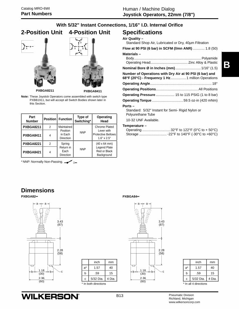
B13 Pneumatic DivisionRichland, Michiganwww.wilkersoncorp.com
Human / Machine DialogJoystick Operators, 22mm (7/8")
Catalog MRO-6WI
Part Numbers
D
BC
AA B
PXBGA8411PXBGA8211
With 5/32" Instant Connections, 1/16" I.D. Internal Orifice
2-Position Unit 4-Position Unit
DimensionsPXBGA82••
SpecificationsAir Quality –
Standard Shop Air, Lubricated or Dry, 40µm Filtration
Flow at 90 PSI (6 bar) in SCFM (l/mn ANR) ............ 1.8 (50)
Materials – Body ...................................................................... Polyamide Operating Head....................................... Zinc Alloy & Plastic
Nominal Bore Ø in Inches (mm) ..........................1/16" (1.5)
Number of Operations with Dry Air at 90 PSI (6 bar) and 68°F (20°C) - Frequency 1 Hz ................1 million Operations
Operating Angle ............................................................... 18°
Operating Positions........................................... All Positions
Operating Pressure ................... 15 to 115 PSIG (1 to 8 bar)
Operating Torque ................................59.5 oz-in (420 mNm)
Ports – Standard: 5/32" Instant for Semi- Rigid Nylon or Polyurethane Tube
10-32 UNF Available.
Temperature – Operating .............................32°F to 122°F (0°C to + 50°C) Storage ............................ -22°F to 140°F (-30°C to +60°C)
Note: These Joystick Operators come assembled with switch type PXBB1911, but will accept all Switch Bodies shown later in this Section.
* In both directions
inch mm
a* 1.57 40
b .59 15
c 5/32 Dia. 4 Dia.
PartNumber
Position FunctionType of
Switching*Operating
Head
PXBGA8211 2 MaintainedPosition in Each
Direction
NNP
Chrome Plated Lever with
Protective Bellows 1.6" x 2.5"
PXBGA8411 4
PXBGA8221 2 Spring Return in
Each Direction
NNP
(40 x 64 mm) Legend Plate Red or Black Background
PXBGA8421 4
* NNP: Normally Non-Passing.
PXBGA84••
2.36(60)
2.28(58)
3.43(87)
1.18(30)
a a
cbb
2.36(60)
2.28(58)
3.43(87)
1.18(30)
a a
cbb
* In all 4 directions
inch mm
a* 1.57 40
b .59 15
c 5/32 Dia. 4 Dia.
B
Pneumatic DivisionRichland, Michiganwww.wilkersoncorp.com
B14
=
=
=
=
7.32(186)
6.30(160)
5.31(135) A B
3x ø.35 (9)
(1)5.39(137)
5.77(146.5)
5.98(152)
1.14 (29) .57
(14.5)
1.06(27)
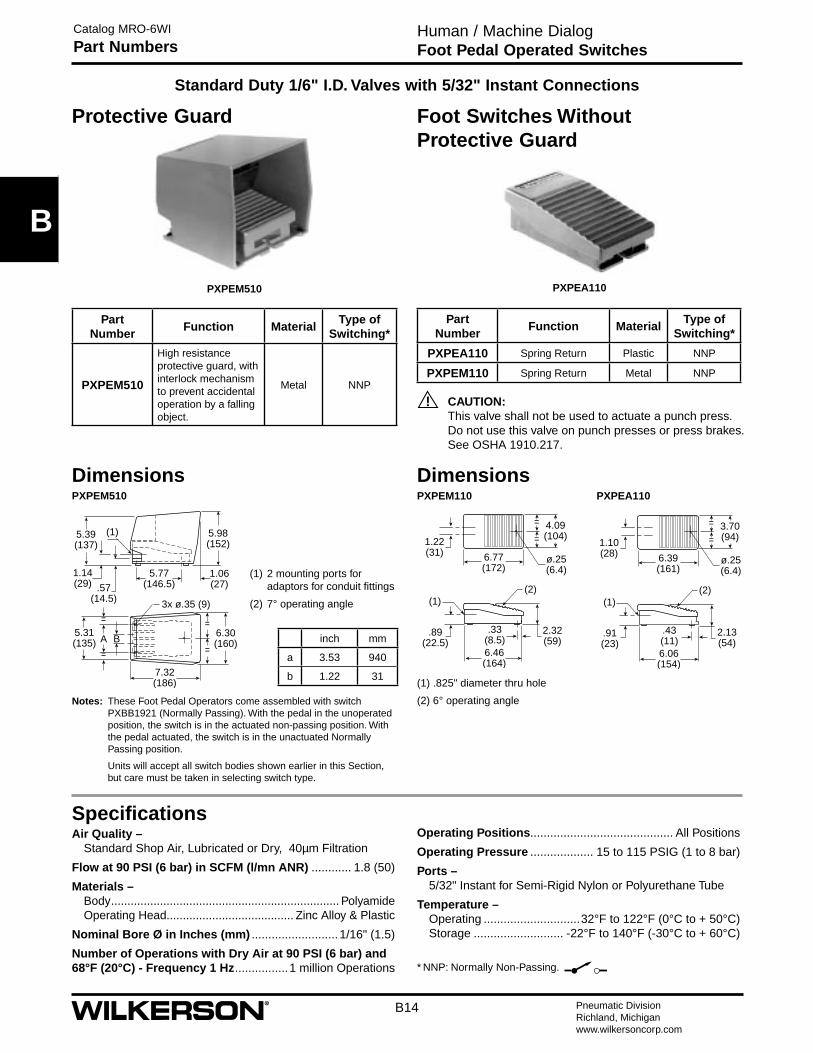
Human / Machine DialogFoot Pedal Operated Switches
Catalog MRO-6WI
Part Numbers
Standard Duty 1/6" I.D. Valves with 5/32" Instant Connections
PXPEM510 PXPEA110
Foot Switches Without Protective Guard
Notes: These Foot Pedal Operators come assembled with switch PXBB1921 (Normally Passing). With the pedal in the unoperated position, the switch is in the actuated non-passing position. With the pedal actuated, the switch is in the unactuated Normally Passing position.
Units will accept all switch bodies shown earlier in this Section, but care must be taken in selecting switch type.
DimensionsPXPEM510
(1) .825" diameter thru hole
(2) 6° operating angle
PXPEM110 PXPEA110
=
=4.09(104)
6.77(172)
1.22(31)
ø.25 (6.4)
(1)(2)
6.46(164)
.33(8.5)
.89(22.5)
2.32(59)
=
=3.70(94)
6.39(161)
1.10(28)
ø.25 (6.4)
(1)(2)
6.06(154)
.43(11)
.91(23)
2.13(54)
Protective Guard
CAUTION: This valve shall not be used to actuate a punch press. Do not use this valve on punch presses or press brakes. See OSHA 1910.217.
!
(1) 2 mounting ports for adaptors for conduit fittings
(2) 7° operating angle
Air Quality – Standard Shop Air, Lubricated or Dry, 40µm Filtration
Flow at 90 PSI (6 bar) in SCFM (l/mn ANR) ............ 1.8 (50)
Materials – Body ...................................................................... Polyamide Operating Head....................................... Zinc Alloy & Plastic
Nominal Bore Ø in Inches (mm) ..........................1/16" (1.5)
Number of Operations with Dry Air at 90 PSI (6 bar) and 68°F (20°C) - Frequency 1 Hz ................1 million Operations
PartNumber
Function MaterialType of
Switching*
PXPEA110 Spring Return Plastic NNP
PXPEM110 Spring Return Metal NNP
PartNumber
Function MaterialType of
Switching*
PXPEM510
High resistance protective guard, with interlock mechanism to prevent accidental operation by a falling object.
Metal NNP
* NNP: Normally Non-Passing.
inch mm
a 3.53 940
b 1.22 31
Dimensions
Operating Positions........................................... All Positions
Operating Pressure ................... 15 to 115 PSIG (1 to 8 bar)
Ports – 5/32" Instant for Semi-Rigid Nylon or Polyurethane Tube
Temperature – Operating .............................32°F to 122°F (0°C to + 50°C) Storage ........................... -22°F to 140°F (-30°C to + 60°C)
Specifications
B
B15 Pneumatic DivisionRichland, Michiganwww.wilkersoncorp.com
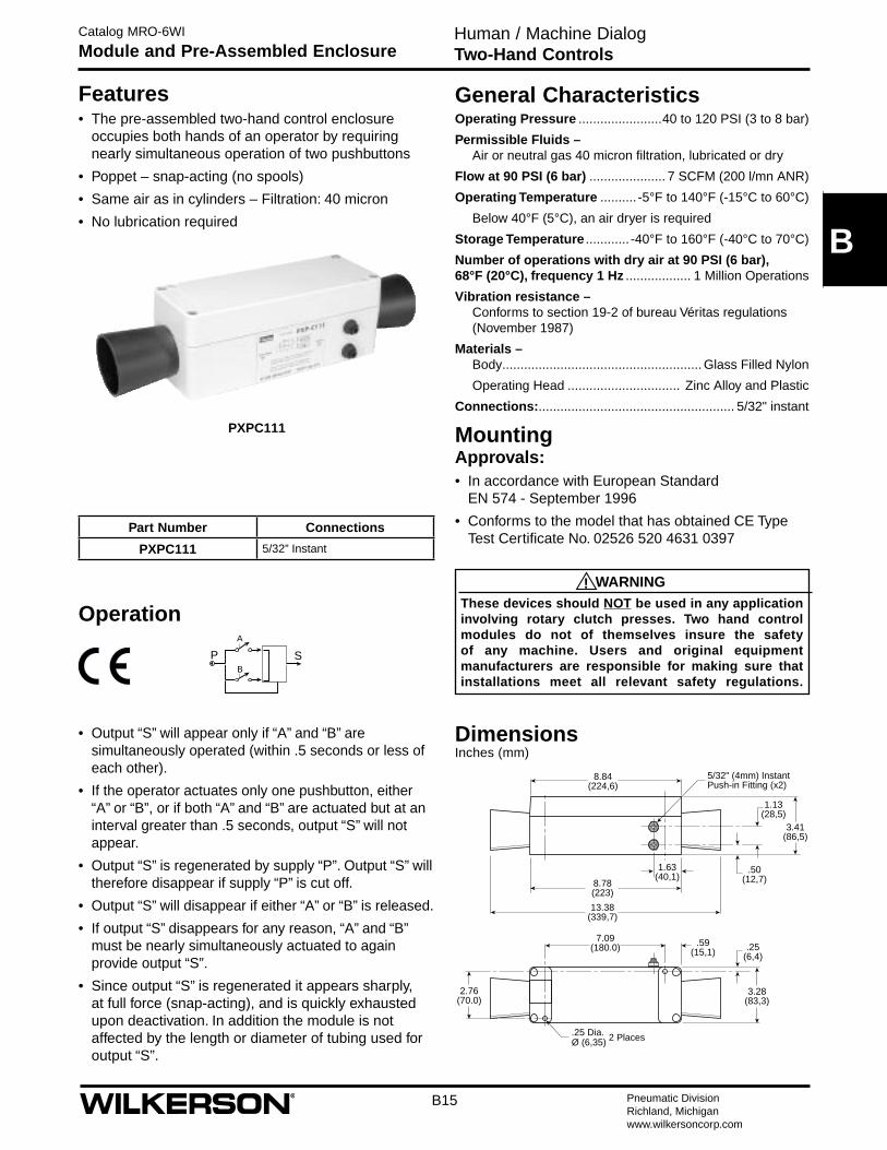
Catalog MRO-6WI
Module and Pre-Assembled Enclosure
A
B
P S
3.28(83,3)
.59(15,1) .25
(6,4)
7.09(180.0)
2.76(70.0)
8.84(224,6)
3.41(86,5)
1.13(28,5)
.50(12,7)
13.38(339,7)
8.78(223)
1.63 (40,1)
5/32" (4mm) Instant Push-in Fitting (x2)
.25 Dia. 2 PlacesØ (6,35)
Features • The pre-assembled two-hand control enclosure
occupies both hands of an operator by requiring nearly simultaneous operation of two pushbuttons
• Poppet – snap-acting (no spools)
• Same air as in cylinders – Filtration: 40 micron
• No lubrication required
PXPC111
WARNINGThese devices should NOT be used in any application involving rotary clutch presses. Two hand control modules do not of themselves insure the safety of any machine. Users and original equipment manufacturers are responsible for making sure that installations meet all relevant safety regulations.
!
General CharacteristicsOperating Pressure .......................40 to 120 PSI (3 to 8 bar)
Permissible Fluids – Air or neutral gas 40 micron filtration, lubricated or dry
Flow at 90 PSI (6 bar) ..................... 7 SCFM (200 l/mn ANR)
Operating Temperature .......... -5°F to 140°F (-15°C to 60°C)
Below 40°F (5°C), an air dryer is required
Storage Temperature ............ -40°F to 160°F (-40°C to 70°C)
Number of operations with dry air at 90 PSI (6 bar), 68°F (20°C), frequency 1 Hz .................. 1 Million Operations
Vibration resistance – Conforms to section 19-2 of bureau Véritas regulations (November 1987)
Materials – Body ....................................................... Glass Filled Nylon
Operating Head ............................... Zinc Alloy and Plastic
Connections: ...................................................... 5/32" instant
Mounting Approvals:• In accordance with European Standard
EN 574 - September 1996
• Conforms to the model that has obtained CE Type Test Certificate No. 02526 520 4631 0397
Dimensions Inches (mm)
Operation
• Output “S” will appear only if “A” and “B” are simultaneously operated (within .5 seconds or less of each other).
• If the operator actuates only one pushbutton, either “A” or “B”, or if both “A” and “B” are actuated but at an interval greater than .5 seconds, output “S” will not appear.
• Output “S” is regenerated by supply “P”. Output “S” will therefore disappear if supply “P” is cut off.
• Output “S” will disappear if either “A” or “B” is released.
• If output “S” disappears for any reason, “A” and “B” must be nearly simultaneously actuated to again provide output “S”.
• Since output “S” is regenerated it appears sharply, at full force (snap-acting), and is quickly exhausted upon deactivation. In addition the module is not affected by the length or diameter of tubing used for output “S”.
Part Number Connections
PXPC111 5/32” Instant
Human / Machine DialogTwo-Hand Controls
B
Pneumatic DivisionRichland, Michiganwww.wilkersoncorp.com
B16
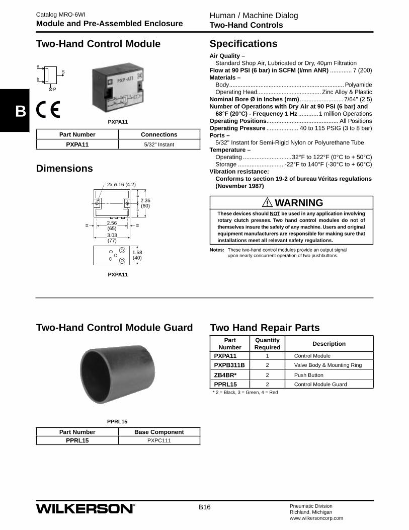
Human / Machine DialogTwo-Hand Controls
Catalog MRO-6WI
Module and Pre-Assembled Enclosure
PPRL15
Two-Hand Control Module Guard
Dimensions
=
=
=
===
2.36(60)
1.58(40)
3.03(77)
2.56(65)
2x ø.16 (4.2)
Part Number Base ComponentPPRL15 PXPC111
PXPA11
a
b
P
S
PXPA11
Two-Hand Control Module
Part Number Connections
PXPA11 5/32" Instant
Notes: These two-hand control modules provide an output signal upon nearly concurrent operation of two pushbuttons.
Air Quality – Standard Shop Air, Lubricated or Dry, 40µm Filtration
Flow at 90 PSI (6 bar) in SCFM (l/mn ANR) ............. 7 (200)Materials –
Body ...................................................................... Polyamide Operating Head....................................... Zinc Alloy & Plastic
Nominal Bore Ø in Inches (mm) ..........................7/64" (2.5)Number of Operations with Dry Air at 90 PSI (6 bar) and
68°F (20°C) - Frequency 1 Hz ............1 million OperationsOperating Positions........................................... All PositionsOperating Pressure ................... 40 to 115 PSIG (3 to 8 bar)Ports –
5/32" Instant for Semi-Rigid Nylon or Polyurethane TubeTemperature –
Operating .............................32°F to 122°F (0°C to + 50°C) Storage ........................... -22°F to 140°F (-30°C to + 60°C)
Vibration resistance: Conforms to section 19-2 of bureau Véritas regulations (November 1987)
Specifications
WARNINGThese devices should NOT be used in any application involving rotary clutch presses. Two hand control modules do not of themselves insure the safety of any machine. Users and original equipment manufacturers are responsible for making sure that installations meet all relevant safety regulations.
!
Two Hand Repair PartsPart
NumberQuantity Required
Description
PXPA11 1 Control Module
PXPB311B 2 Valve Body & Mounting Ring
ZB4BR* 2 Push Button
PPRL15 2 Control Module Guard* 2 = Black, 3 = Green, 4 = Red
K
K1 Pneumatic DivisionRichland, Michiganwww.wilkersoncorp.com
Safety Guide For Selecting And Using Pneumatic Division Products And Related Accessories
WARNING:FAILURE OR IMPROPER SELECTION OR IMPROPER USE OF PNEUMATIC DIVISION PRODUCTS, ASSEMBLIES OR RELATED ITEMS (“PRODUCTS”) CAN CAUSE DEATH, PERSONAL INJURY, AND PROPERTY DAMAGE. POSSIBLE CONSEQUENCES OF FAILURE OR IMPROPER SELECTION OR IMPROPER USE OF THESE PRODUCTS INCLUDE BUT ARE NOT LIMITED TO:• Unintended or mistimed cycling or motion of machine members or failure to cycle• Work pieces or component parts being thrown off at high speeds.• Failure of a device to function properly for example, failure to clamp or unclamp an associated item or device.• Explosion• Suddenly moving or falling objects.• Release of toxic or otherwise injurious liquids or gasses.Before selecting or using any of these Products, it is important that you read and follow the instructions below.
!
Pneumatic ProductsCatalog MRO-6WI
Safety Guide
1. GENERAL INSTRUCTIONS 1.1. Scope: This safety guide is designed to cover general guidelines on the installation, use, and maintenance of Pneumatic Division
Valves, FRLs (Filters pressure Regulators and Lubricators), Vacuum products and related accessory components. 1.2. Fail-Safe: Valves, FRLs, Vacuum products and their related components can and do fail without warning for many reasons. Design
all systems and equipment in a fail-safe mode, so that failure of associated valves, FRLs or Vacuum products will not endanger persons or property.
1.3 Relevant International Standards: For a good guide to the application of a broad spectrum of pneumatic fluid power devices see: ISO 4414:1998, Pneumatic Fluid Power – General Rules Relating to Systems. See www.iso.org for ordering information.
1.4. Distribution: Provide a copy of this safety guide to each person that is responsible for selection, installation, or use of Valves, FRLs or Vacuum products. Do not select, or use Wilkerson valves, FRLs or vacuum products without thoroughly reading and understanding this safety guide as well as the specific Wilkerson publications for the products considered or selected.
1.5. User Responsibility: Due to the wide variety of operating conditions and applications for valves, FRLs, and vacuum products Wilkerson and its distributors do not represent or warrant that any particular valve, FRL or vacuum product is suitable for any specific end use system. This safety guide does not analyze all technical parameters that must be considered in selecting a product. The user, through its own analysis and testing, is solely responsible for: • Making the final selection of the appropriate valve, FRL, Vacuum component, or accessory.
• Assuring that all user’s performance, endurance, maintenance, safety, and warning requirements are met and that the application presents no health or safety hazards.
• Complying with all existing warning labels and / or providing all appropriate health and safety warnings on the equipment on which the valves, FRLs or Vacuum products are used; and,
• Assuring compliance with all applicable government and industry standards. 1.6. Safety Devices: Safety devices should not be removed, or defeated. 1.7. Warning Labels: Warning labels should not be removed, painted over or otherwise obscured. 1.8. Additional Questions: Call the appropriate Wilkerson technical service department if you have any questions or require any
additional information. See the Wilkerson publication for the product being considered or used, or call 269-629-2550, or go to www.wilkersoncorp.com, for telephone numbers of the appropriate technical service department.
2. PRODUCT SELECTION INSTRUCTIONS 2.1. Flow Rate: The flow rate requirements of a system are frequently the primary consideration when designing any pneumatic system.
System components need to be able to provide adequate flow and pressure for the desired application. 2.2. Pressure Rating: Never exceed the rated pressure of a product. Consult product labeling, Pneumatic Division catalogs or the
instruction sheets supplied for maximum pressure ratings. 2.3. Temperature Rating: Never exceed the temperature rating of a product. Excessive heat can shorten the life expectancy of a product
and result in complete product failure. 2.4. Environment: Many environmental conditions can affect the integrity and suitability of a product for a given application. Pneumatic
Division products are designed for use in general purpose industrial applications. If these products are to be used in unusual circumstances such as direct sunlight and/or corrosive or caustic environments, such use can shorten the useful life and lead to premature failure of a product.
2.5. Lubrication and Compressor Carryover: Some modern synthetic oils can and will attack nitrile seals. If there is any possibility of synthetic oils or greases migrating into the pneumatic components check for compatibility with the seal materials used. Consult the factory or product literature for materials of construction.
2.6. Polycarbonate Bowls and Sight Glasses: To avoid potential polycarbonate bowl failures: • Do not locate polycarbonate bowls or sight glasses in areas where they could be subject to direct sunlight, impact blow, or temperatures outside of the rated range.
• Do not expose or clean polycarbonate bowls with detergents, chlorinated hydro-carbons, keytones, esters or certain alcohols. • Do not use polycarbonate bowls or sight glasses in air systems where compressors are lubricated with fire resistant fluids such as
phosphate ester and di-ester lubricants.
K
Pneumatic DivisionRichland, Michiganwww.wilkersoncorp.com
K2
Pneumatic ProductsCatalog MRO-6WI
Safety Guide
2.7. Chemical Compatibility: For more information on plastic component chemical compatibility see Pneumatic Division technical bulletins Tec-3, Tec-4, and Tec-5
2.8. Product Rupture: Product rupture can cause death, serious personal injury, and property damage. • Do not connect pressure regulators or other Pneumatic Division products to bottled gas cylinders.
• Do not exceed the maximum primary pressure rating of any pressure regulator or any system component. • Consult product labeling or product literature for pressure rating limitations.3. PRODUCT ASSEMBLY AND INSTALLATION INSTRUCTIONS 3.1. Component Inspection: Prior to assembly or installation a careful examination of the valves, FRLs or vacuum products must be
performed. All components must be checked for correct style, size, and catalog number. DO NOT use any component that displays any signs of nonconformance.
3.2. Installation Instructions: Wilkerson published Installation Instructions must be followed for installation of Wilkerson valves, FRLs and vacuum components. These instructions are provided with every Wilkerson valve or FRL sold, or by calling 269-629-2550, or at www.wilkersoncorp.com.
3.3. Air Supply: The air supply or control medium supplied to Valves, FRLs and Vacuum components must be moisture-free if ambient temperature can drop below freezing
4. VALVE AND FRL MAINTENANCE AND REPLACEMENT INSTRUCTIONS 4.1. Maintenance: Even with proper selection and installation, valve, FRL and vacuum products service life may be significantly reduced
without a continuing maintenance program. The severity of the application, risk potential from a component failure, and experience with any known failures in the application or in similar applications should determine the frequency of inspections and the servicing or replacement of Pneumatic Division products so that products are replaced before any failure occurs. A maintenance program must be established and followed by the user and, at minimum, must include instructions 4.2 through 4.10.
4.2. Installation and Service Instructions: Before attempting to service or replace any worn or damaged parts consult the appropriate Service Bulletin for the valve or FRL in question for the appropriate practices to service the unit in question. These Service and Installation Instructions are provided with every Wilkerson valve and FRL sold, or are available by calling 269-629-2550, or by accessing the Wilkerson web site at www.wilkersoncorp.com.
4.3. Lockout / Tagout Procedures: Be sure to follow all required lockout and tagout procedures when servicing equipment. For more information see: OSHA Standard – 29 CFR, Part 1910.147, Appendix A, The Control of Hazardous Energy – (Lockout / Tagout)
4.4. Visual Inspection: Any of the following conditions requires immediate system shut down and replacement of worn or damaged components: • Air leakage: Look and listen to see if there are any signs of visual damage to any of the components in the system. Leakage is an indication of worn or damaged components.
• Damaged or degraded components: Look to see if there are any visible signs of wear or component degradation. • Kinked, crushed, or damaged hoses. Kinked hoses can result in restricted air flow and lead to unpredictable system behavior. • Any observed improper system or component function: Immediately shut down the system and correct malfunction. • Excessive dirt build-up: Dirt and clutter can mask potentially hazardous situations. Caution: Leak detection solutions should be rinsed off after use. 4.5. Routine Maintenance Issues:
• Remove excessive dirt, grime and clutter from work areas. • Make sure all required guards and shields are in place. 4.6. Functional Test: Before initiating automatic operation, operate the system manually to make sure all required functions operate
properly and safely. 4.7. Service or Replacement Intervals: It is the user’s responsibility to establish appropriate service intervals. Valves, FRLs and vacuum
products contain components that age, harden, wear, and otherwise deteriorate over time. Environmental conditions can significantly accelerate this process. Valves, FRLs and vacuum components need to be serviced or replaced on routine intervals. Service intervals need to be established based on: • Previous performance experiences.
• Government and / or industrial standards. • When failures could result in unacceptable down time, equipment damage or personal injury risk. 4.8. Servicing or Replacing of any Worn or Damaged Parts: To avoid unpredictable system behavior that can cause death, personal
injury and property damage: • Follow all government, state and local safety and servicing practices prior to service including but not limited to all OSHA Lockout Tagout procedures (OSHA Standard – 29 CFR, Part 1910.147, Appendix A, The Control of Hazardous Energy – Lockout / Tagout).
• Disconnect electrical supply (when necessary) before installation, servicing, or conversion. • Disconnect air supply and depressurize all air lines connected to system and Pneumatic Division products before installation, service,
or conversion. • Installation, servicing, and / or conversion of these products must be performed by knowledgeable personnel who understand how
pneumatic products are to be applied. • After installation, servicing, or conversions air and electrical supplies (when necessary) should be connected and the product tested
for proper function and leakage. If audible leakage is present, or if the product does not operate properly, do not put product or system into use.
• Warnings and specifications on the product should not be covered or painted over. If masking is not possible, contact your local representative for replacement labels.
4.9. Putting Serviced System Back into Operation: Follow the guidelines above and all relevant Installation and Maintenance Instructions supplied with the valve FRL or vacuum component to insure proper function of the system.
Pneumatic ProductsCatalog MRO-6WI
Offer of Sale
K
K3 Pneumatic DivisionRichland, Michiganwww.wilkersoncorp.com
The items described in this document and other documents or descriptions provided by , its subsidiaries and its authorized distributors, are hereby offered for sale at prices to be established by The Company, its subsidiaries and its authorized distributors. This offer and its acceptance by any customer (“Buyer”) shall be governed by all of the following Terms and Conditions. Buyer’s order for any such item, when communicated to The Company, its subsidiaries or an authorized distributor (“Seller”) verbally or in writing, shall constitute ac-ceptance of this offer.
1. Terms and Conditions of Sale: All descriptions, quotations, proposals, offers, acknowledgments, acceptances and sales of Seller’s products are subject to and shall be governed exclusively by the terms and conditions stated herein. Buyer’s acceptance of any offer to sell is limited to these terms and conditions. Any terms or conditions in addition to, or inconsistent with those stated herein, proposed by Buyer in any acceptance of an offer by Seller, are hereby objected to. No such additional, different or inconsistent terms and conditions shall become part of the contract between Buyer and Seller unless expressly accepted in writing by Seller. Seller’s acceptance of any offer to purchase by Buyer is expressly conditional upon Buyer’s assent to all the terms and conditions stated herein, including any terms in addition to, or inconsistent with those contained in Buyer’s offer. Acceptance of Seller’s products shall in all events constitute such assent.
2. Payment: Payment shall be made by Buyer net 30 days from the date of delivery of the items purchased hereunder. Amounts not timely paid shall bear interest at the maximum rate permitted by law for each month or portion thereof that the Buyer is late in making payment. Any claims by Buyer for omissions or shortages in a shipment shall be waived unless Seller receives notice thereof within 30 days after Buyer’s receipt of the shipment.
3. Delivery: Unless otherwise provided on the face hereof, delivery shall be made F.O.B. Seller’s plant. Regardless of the method of delivery, however, risk of loss shall pass to Buyer upon Seller’s delivery to a carrier. Any delivery dates shown are approximate only and Seller shall have no liability for any delays in delivery.
4. Warranty: Seller warrants that the items sold hereunder shall be free from defects in material or workmanship for a period of 18 months from date of shipment from The Company. THIS WARRANTY COMPRISES THE SOLE AND ENTIRE WARRANTY PERTAINING TO ITEMS PROVIDED HEREUNDER. SELLER MAKES NO OTHER WARRANTY, GUARANTEE, OR REPRESENTATION OF ANY KIND WHATSOEVER. ALL OTHER WARRANTIES, INCLUDING BUT NOT LIMITED TO, MERCHANTABILITY AND FITNESS FOR PURPOSE, WHETHER EXPRESS, IMPLIED, OR ARISING BY OPERATION OF LAW, TRADE USAGE, OR COURSE OF DEALING ARE HEREBY DISCLAIMED.
NOTWITHSTANDING THE FOREGOING, THERE ARE NO WARRANTIES WHATSOEVER ON ITEMS BUILT OR ACQUIRED WHOLLY OR PARTIALLY, TO BUYER’S DESIGN OR SPECIFICATIONS.
5. Limitation of Remedy: SELLER’S LIABILITY ARISING FROM OR IN ANY WAY CONNECTED WITH THE ITEMS SOLD OR THIS CONTRACT SHALL BE LIMITED EXCLUSIVELY TO REPAIR OR REPLACEMENT OF THE ITEMS SOLD OR REFUND OF THE PURCHASE PRICE PAID BY BUYER, AT SELLER’S SOLE OPTION. IN NO EVENT SHALL SELLER BE LIABLE FOR ANY INCIDENTAL, CONSEQUENTIAL OR SPECIAL DAMAGES OF ANY KIND OR NATURE WHATSOEVER, INCLUDING BUT NOT LIMITED TO LOST PROFITS ARISING FROM OR IN ANY WAY CONNECTED WITH THIS AGREEMENT OR ITEMS SOLD HEREUNDER, WHETHER ALLEGED TO ARISE FROM BREACH OF CONTRACT, EXPRESS OR IMPLIED WARRANTY, OR IN TORT, INCLUDING WITHOUT LIMITATION, NEGLIGENCE, FAILURE TO WARN OR STRICT LIABILITY.
6. Changes, Reschedules and Cancellations: Buyer may request to modify the designs or specifications for the items sold hereunder as well as the quantities and delivery dates thereof, or may request to cancel all or part of this order, however, no such requested modification or cancellation shall become part of the contract between Buyer and Seller unless accepted by Seller in a written amendment to this Agreement. Acceptance of any such requested modification or cancellation shall be at Seller’s discretion, and shall be upon such terms and conditions as Seller may require.
7. Special Tooling: A tooling charge may be imposed for any special tooling, including without limitations, dies, fixtures, molds and patterns, acquired to manufacture items sold pursuant to this contract. Such special tooling shall be and remain Seller’s property notwithstanding payment of any charges by Buyer. In no event will Buyer acquire any interest in apparatus belonging to Seller which is utilized in the manufacture of the items sold hereunder, even if such apparatus has been specially converted or adapted for such manufacture and notwithstanding any charges paid by Buyer. Unless otherwise agreed, Seller shall have the right to alter,
discard or otherwise dispose of any special tooling or other property in its sole discretion at any time.
8. Buyer’s Property: Any designs, tools, patterns, materials, drawings, confidential information or equipment furnished by Buyer, or any other items which become Buyer’s property, may be considered obsolete and may be destroyed by Seller after two (2) consecutive years have elapsed without Buyer placing an order for the items which are manufactured using such property. Seller shall not be responsible for any loss or damage to such property while it is in Seller’s possession or control.
9. Taxes: Unless otherwise indicated on the face hereof, all prices and charges are exclusive of excise, sales, use, property, occupational or like taxes which may be imposed by any taxing authority upon the manufacture, sale or delivery of the items sold hereunder. If any such taxes must be paid by Seller or if Seller is liable for the collection of such tax, the amount thereof shall be in addition to the amounts for the items sold. Buyer agrees to pay all such taxes or to reimburse Seller therefore upon receipt of its invoice. If Buyer claims exemption from any sales, use or other tax imposed by any taxing authority, Buyer shall save Seller harmless from and against any such tax, together with any interest or penalties thereon which may be assessed if the items are held to be taxable.
10. Indemnity For Infringement of Intellectual Property Rights: Seller shall have no liability for infringement of any patents, trademarks, copyrights, trade dress, trade secrets or similar rights except as provided in this Part 10. Seller will defend and indemnify Buyer against allegations of infringement of U.S. patents, U.S. trademarks, copyrights, trade dress and trade secrets (hereinafter “Intellectual Property Rights”). Seller will defend at its expense and will pay the cost of any settlement or damages awarded in an action brought against Buyer based on an allegation that an item sold pursuant to this contract infringes the Intellectual Property Rights of a third party. Seller’s obligation to defend and indemnify Buyer is contingent on Buyer notifying Seller within ten (10) days after Buyer becomes aware of such allegations of infringement, and Seller having sole control over the defense of any allegations or actions including all negotiations for settlement or compromise. If an item sold hereunder is subject to a claim that it infringes the Intellectual Property Rights of a third party, Seller may, at its sole expense and option, procure for Buyer the right to continue using said item, replace or modify said item so as to make it noninfringing, or offer to accept return of said item and return the purchase price less a reasonable allowance for depreciation. Notwithstanding the foregoing, Seller shall have no liability for claims of infringement based on information provided by Buyer, or directed to items delivered hereunder for which the designs are specified in whole or part by Buyer, or infringements resulting from the modification, combination or use in a system of any item sold hereunder. The foregoing provisions of this Part 10 shall constitute Seller’s sole and exclusive liability and Buyer’s sole and exclusive remedy for infringement of Intellectual Property Rights.
If a claim is based on information provided by Buyer or if the design for an item delivered hereunder is specified in whole or in part by Buyer, Buyer shall defend and indemnify Seller for all costs, expenses or judgements resulting from any claim that such item infringes any patent, trademark, copyright, trade dress, trade secret or any similar right.
11. Force Majeure: Seller does not assume the risk of and shall not be liable for delay or failure to perform any of Seller’s obligations by reason of circumstances beyond the reasonable control of Seller (hereinafter “Events of Force Majeure”). Events of Force Majeure shall include without limitation, accidents, acts of God, strikes or labor disputes, acts, laws, rules or regulations of any government or government agency, fires, floods, delays or failures in delivery of carriers or suppliers, shortages of materials and any other cause beyond Seller’s control.
12. Entire Agreement/Governing Law: The terms and conditions set forth herein, together with any amendments, modifications and any different terms or conditions expressly accepted by Seller in writing, shall constitute the entire Agreement concerning the items sold, and there are no oral or other representations or agreements which pertain thereto. This Agreement shall be governed in all respects by the law of the State of Ohio. No actions arising out of sale of the items sold hereunder or this Agreement may be brought by either party more than two (2) years after the cause of action accrues.
Top Related