


Languages
Pages
Legal


Platform design using dynamic motor, electronics, and transmission models
Avik DePost-doctoral scholar; Ph.D. with Daniel Koditschek (2017)
Electrical & Systems Engineering, University of PennsylvaniaCofounder & CTO, Ghost Robotics (Philadelphia)
ARL/GDRS RCTA W911NF-1020016AFOSR MURI FA9550-10-1-0567
NSF CABiR (CDI 1028237)ONR/OSD Vanevar Bush Fellowship N00014-16-1-2817

Motivation: analytically-guided design
Motor
Motor controller
Gearbox
Compliant element
Leg kinematics
Dynamic task specification for gearbox selection
e.g. [De et al (2011)]
e.g. [Hollerbach (1991)]
[Wensing (2017)]
Huge amount of past work…
𝑢, 𝑘𝑜, …
𝑟, 𝑑, 𝑙, … , 𝐿, 𝑅, …
𝐺, 𝐽𝐺
𝑘, 𝑏, …
𝑙𝑖 , …
Platform morphology
𝑑, 𝜅, 𝜌𝑡, 𝑚𝑡, … e.g. [De et al (in press)]
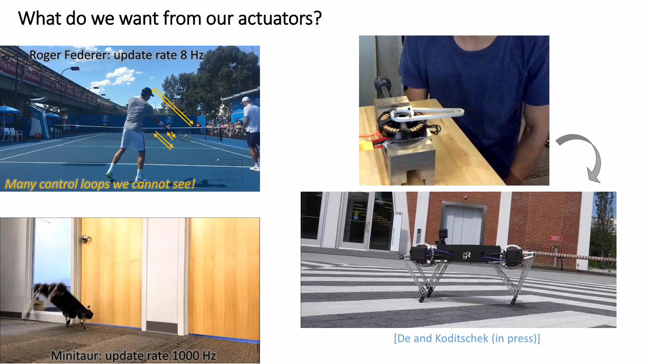
What do we want from our actuators?
Roger Federer: update rate 8 Hz
Minitaur: update rate 1000 Hz
Many control loops we cannot see!
[De and Koditschek (in press)]

Actuators for RoboticsMotor controllers• 50V single power supply• 40A+ RMS• >500A peak (voltage mode), 80A peak (current mode)• EtherCAT interface• ~200us full loop ping• Command: voltage, position, q-current• Sensor info: rotor position, q-current
Motors• BLDC motors• 0.05—0.8kg (not exhaustive)• Specific torque ~4Nm/kg
• Limit 6Nm/kg [Hollerbach (1991)]
Actuator packages• Direct-drive, or with custom gearboxes 7:1 – 25:1• Output position sensors• Interface to analog force sensors

Commonly-used motor models in robotics
http://ctms.engin.umich.edu/CTMS/index.php?example=MotorSpeed§ion=SystemModeling
http://www.vgt.bme.hu/info_en/research/sim/fem/1.htm Deficiencies:• only one control input• does not explain full torque output• underestimates max power/max
speed
Model• 𝜄 current• 𝑣 voltage• 𝐿 inductance• 𝑅 resistance• 𝑘𝑒 back-EMF constant
Problems:• Brittle (hard to generalize)• No analytical insight• Time/computation intensive
Analytical tractability

Equations of motion
• Transform to rotor frame
• Rotor frame EOM don’t have 𝜃𝑒-dependence
• NOTE: almost linear—yes if 𝜔𝑚 slow
• Mechanical subsystem also doesn’t have 𝜃𝑒-dependence
A three-phase BLDC motor model
https://www.mathworks.com/help/physmod/sps/ref/brushlessdcmotor.html
Model• 𝜄, 𝑥 (stator, rotor) currents• 𝑣, 𝑢 (stator, rotor) voltages• 𝐿 inductance• 𝑅 resistance• 𝑘𝑒 back-EMF constant• 𝜔𝑚 mechanical speed• 𝑛 # pole pairs• 𝜃𝑒 electrical angle• 𝛽 𝜃𝑒 back-EMF waveform

Controlling the three-phase model
Candidate controllers:1) Position-based, voltage control
2) Feedforward model-based
Problem: need to know 𝐿, 𝜔𝑚 precisely
3) Use current feedback
4) Other?
Energy balance:
Set control goal:• Minimize 𝑥2• Track desired speed/torque/…
Input electrical
power
Joule heating
Mechanical output power
Transient

“Speed-torque curve”
Recall scalar motor model:
• At equilibrium
Three-phase model:• Eliminate 𝑥2 at equilibrium
Can send → 0 using 𝑢2
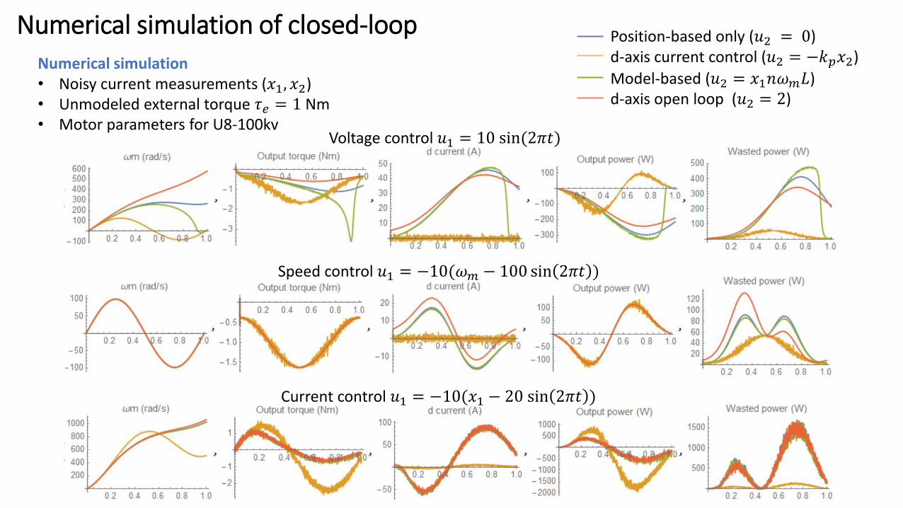
Numerical simulation of closed-loop
Voltage control 𝑢1 = 10 sin(2𝜋𝑡)
Speed control 𝑢1 = −10(𝜔𝑚 − 100 sin 2𝜋𝑡 )
Current control 𝑢1 = −10(𝑥1 − 20 sin 2𝜋𝑡 )
Position-based only (𝑢2 = 0)d-axis current control (𝑢2 = −𝑘𝑝𝑥2)
Model-based (𝑢2 = 𝑥1𝑛𝜔𝑚𝐿)d-axis open loop (𝑢2 = 2)
Numerical simulation• Noisy current measurements (𝑥1, 𝑥2) • Unmodeled external torque 𝜏𝑒 = 1 Nm• Motor parameters for U8-100kv

A more realistic scenario• Introduce sensor errors Δ𝑥1, Δ𝜔𝑚
• Normalize:
• ADC resolution is fixed, i.e.
• Only relevant motor design parameter is 𝐽𝑚• Only control affordance through 𝑘𝑜
External force estimation with sensing noise
Sensing external torque “proprioception”• Momentum observer [De Luca et al (2005)]
• No relation to motor parameters if 𝑘𝑜 can be set arbitrarily

Motor construction design parameters
Two types:• Mechanical – geometry
• Electrical – winding, 𝑅, 𝐿
Metrics• Specific torque (cts/peak), power• Bandwidth [Wensing et al (2017)]• Transparency (?)
• Ease of instantiating impedance control [Hogan (1985)]• Proprioception accuracy
[Hollerbach et al (1991)]
[Seok et al (2012)]
[Kenneally et al (2016)]
[De (2017)]

Modeling motor designTorque constant• Force on a loop• Area of stator tooth• Shear force
Winding wire resistance• Not much wire between stator teeth, i.e.• Length from “perimeter” around teeth
• So resistance
Motor constant• Note: independent of 𝑛 (electrical params)!
Mass• Assume constant density
Specific 𝑲𝒎
* Related to stator aspect ratioPlot from me; data from [Wensing (2017)]
Parameters:• 𝑛 # coils• 𝑙 length of stator• 𝑟 gap radius• 𝑑 stator thickness• 𝑙𝑤 wire length• 𝑣𝑤 wire volume• 𝐴𝑡 area of a stator
tooth
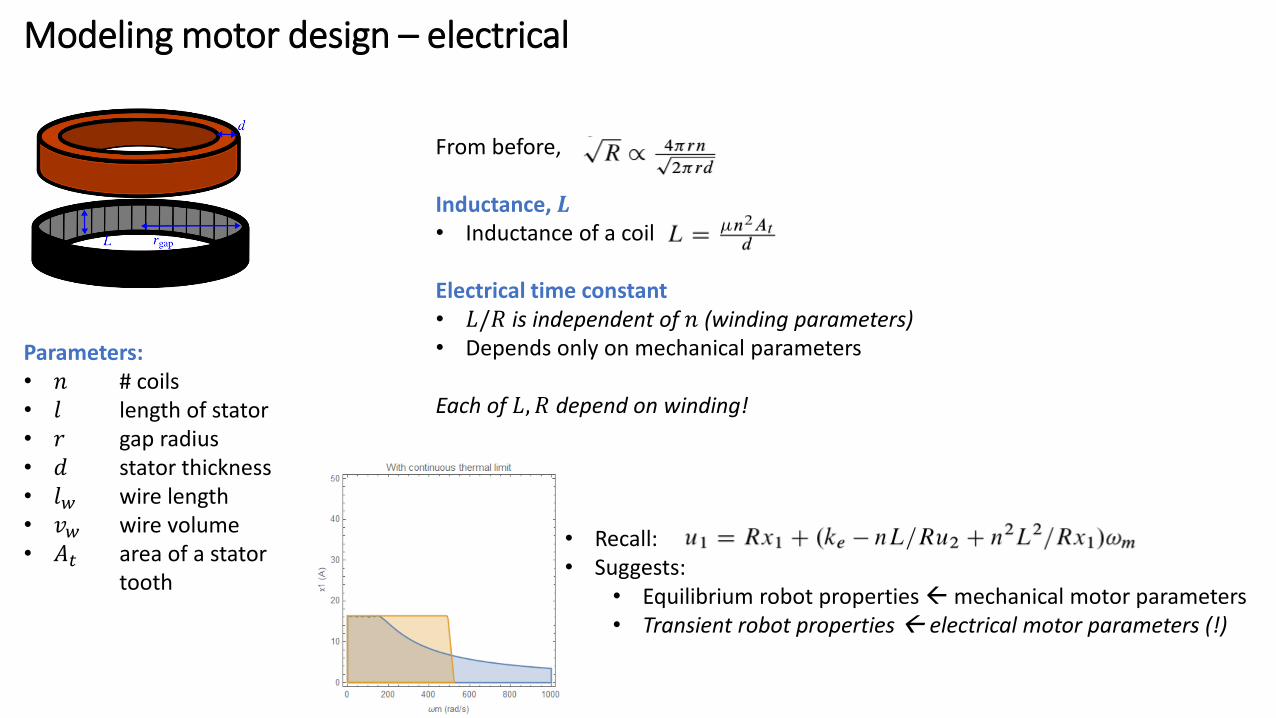
From before,
Inductance, 𝑳• Inductance of a coil
Electrical time constant• 𝐿/𝑅 is independent of 𝑛 (winding parameters)• Depends only on mechanical parameters
Each of 𝐿, 𝑅 depend on winding!
• Recall:• Suggests:
• Equilibrium robot properties mechanical motor parameters• Transient robot properties electrical motor parameters (!)
Modeling motor design – electrical
Parameters:• 𝑛 # coils• 𝑙 length of stator• 𝑟 gap radius• 𝑑 stator thickness• 𝑙𝑤 wire length• 𝑣𝑤 wire volume• 𝐴𝑡 area of a stator
tooth

Other selection metricsThermal specific torque
• Thermal dissipation incorporated into 𝐾𝑚
𝑚
[Kenneally, De, Kod (2016)]
Peak torque• Difficult without finite element
model• Rule of thumb to relate to
continuous
[Hollerbach (1991)]
Proprioceptive sensing error ~𝑱𝒎• Smaller motors always preferred
as sensors
Bandwidth [Wensing (2017)]• Builds on inertia and continuous
torque

Future work
• Combine models (coupled)• Task-optimal platform design
Motor
Motor controller
Gearbox
Compliant element
Leg kinematics
𝑢, 𝑘𝑜, …
𝑟, 𝑑, 𝑙, … , 𝐿, 𝑅, …
𝐺, 𝐽𝐺
𝑘, 𝑏, …
𝑙𝑖 , …
Platform morphology
𝑑, 𝜅, 𝜌𝑡, 𝑚𝑡, …
Top Related