


Languages
Pages
Legal

ELECTRONICS LAB.
PART 2 EXPERIMENTS
Yrd. Doç. Dr. Taha İMECİ
Arş. Gör. Ezgi YAMAÇ
Arş. Gör. Ufuk ŞANVER
İSTANBUL COMMERCE UNIVERSITY

1
Contents
EXPERIMENT: 2.1 ................................................................................................................... 2
EXAMINATION OF A CAPACITOR FILTER .............................................. 2
EXPERIMENT: 2.2 ................................................................................................................... 4
ANALYZING LOAD CURRENT’S EFFECT TO THE FILTER ........................... 4
EXPERIMENT: 2.3 ................................................................................................................... 6
ANALYSIS OF TYPE FILTER .............................................................. 6
EXPERIMENT: 2.4 ................................................................................................................... 8
EXAMINATION OF VOLTAGE DOUBLER ................................................. 8
EXPERIMENT: 2.5 ................................................................................................................... 9
EXAMINATION OF VOLTAGE TRIPPLER ................................................. 9
EXPERIMENT: 2.6 ................................................................................................................. 10
EXAMINATION OF VOLTAGE QUADRUPLER .......................................... 10
2
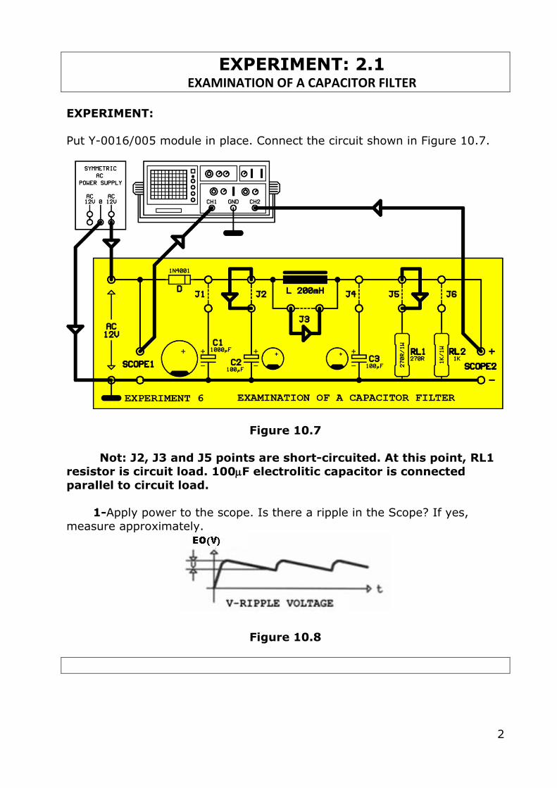
EXPERIMENT: 2.1 EXAMINATION OF A CAPACITOR FILTER
EXPERIMENT:
Put Y-0016/005 module in place. Connect the circuit shown in Figure 10.7.
Figure 10.7
Not: J2, J3 and J5 points are short-circuited. At this point, RL1
resistor is circuit load. 100F electrolitic capacitor is connected
parallel to circuit load.
1-Apply power to the scope. Is there a ripple in the Scope? If yes,
measure approximately.
Figure 10.8
3
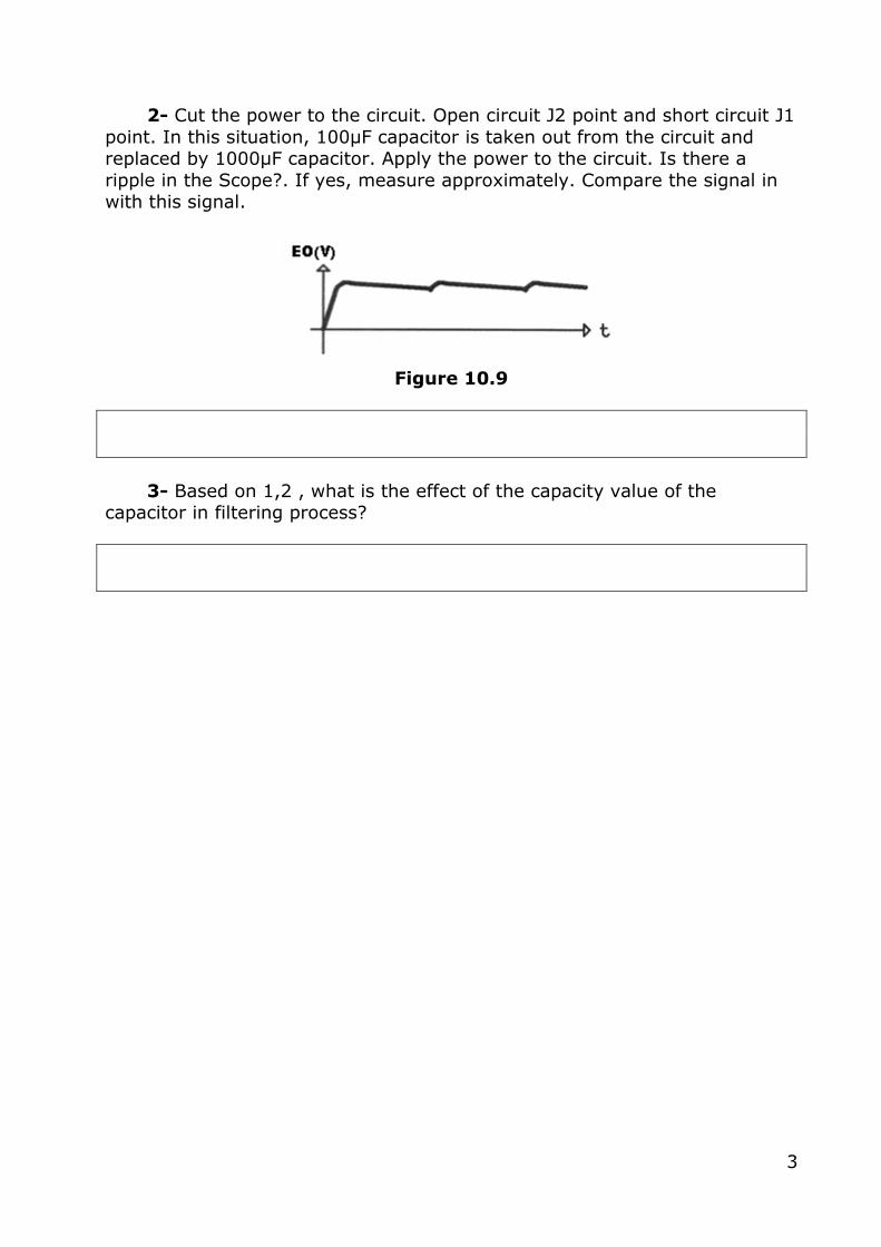
2- Cut the power to the circuit. Open circuit J2 point and short circuit J1
point. In this situation, 100μF capacitor is taken out from the circuit and replaced by 1000μF capacitor. Apply the power to the circuit. Is there a
ripple in the Scope?. If yes, measure approximately. Compare the signal in with this signal.
Figure 10.9
3- Based on 1,2 , what is the effect of the capacity value of the capacitor in filtering process?
4
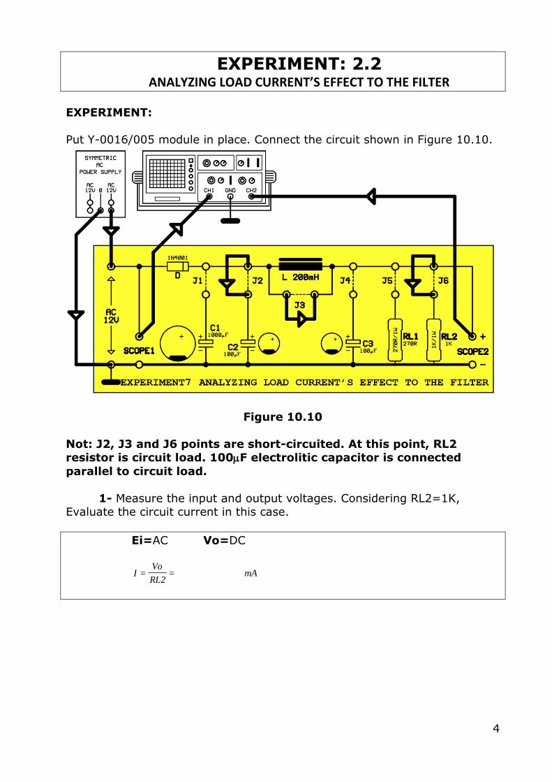
EXPERIMENT: 2.2 ANALYZING LOAD CURRENT’S EFFECT TO THE FILTER
EXPERIMENT:
Put Y-0016/005 module in place. Connect the circuit shown in Figure 10.10.
Figure 10.10
Not: J2, J3 and J6 points are short-circuited. At this point, RL2 resistor is circuit load. 100F electrolitic capacitor is connected
parallel to circuit load.
1- Measure the input and output voltages. Considering RL2=1K, Evaluate the circuit current in this case.
Ei=AC Vo=DC
==2RL
VoI mA
5
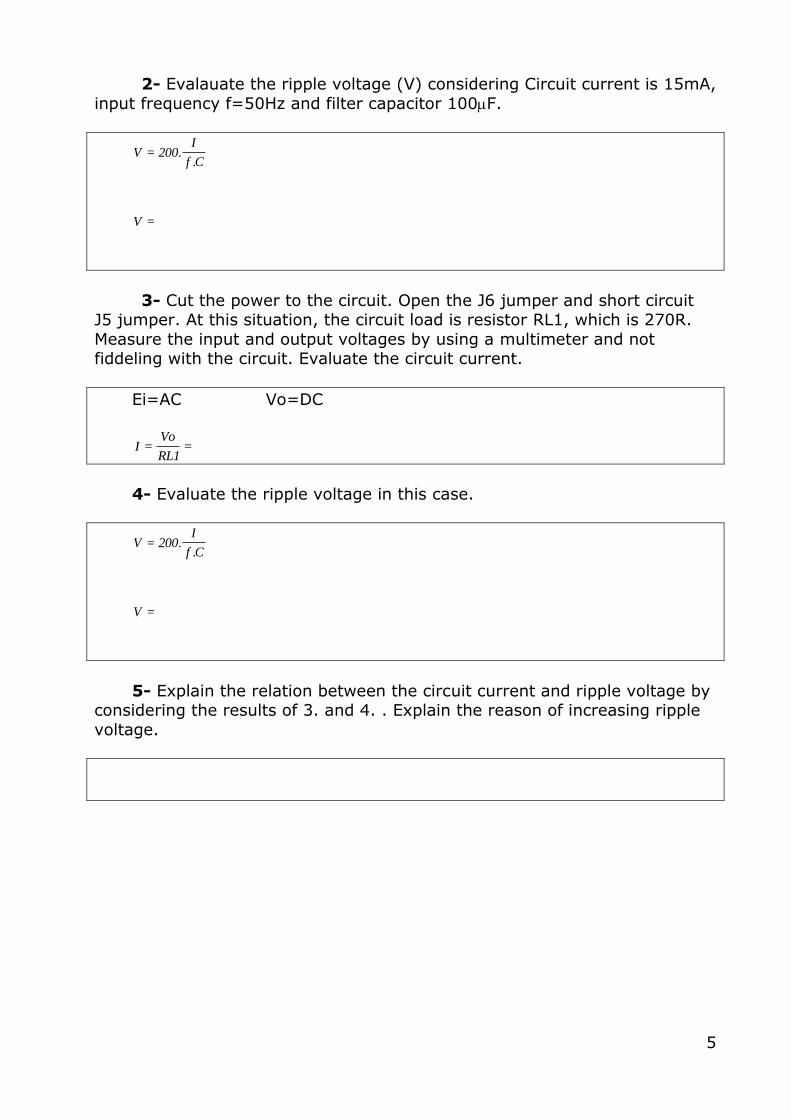
2- Evalauate the ripple voltage (V) considering Circuit current is 15mA,
input frequency f=50Hz and filter capacitor 100F.
=
=
V
C.f
I.200V
3- Cut the power to the circuit. Open the J6 jumper and short circuit J5 jumper. At this situation, the circuit load is resistor RL1, which is 270R.
Measure the input and output voltages by using a multimeter and not fiddeling with the circuit. Evaluate the circuit current.
Ei=AC Vo=DC
==1RL
VoI
4- Evaluate the ripple voltage in this case.
=
=
V
C.f
I.200V
5- Explain the relation between the circuit current and ripple voltage by considering the results of 3. and 4. . Explain the reason of increasing ripple
voltage.
6
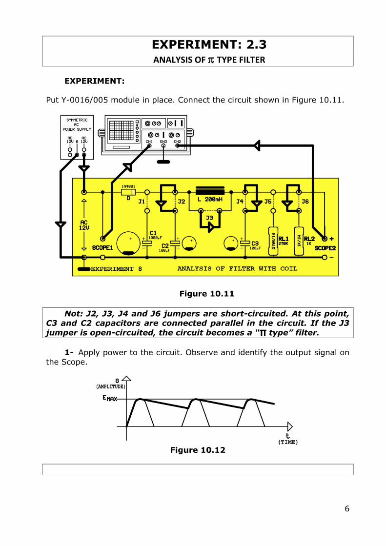
EXPERIMENT: 2.3 ANALYSIS OF TYPE FILTER
EXPERIMENT:
Put Y-0016/005 module in place. Connect the circuit shown in Figure 10.11.
Figure 10.11
Not: J2, J3, J4 and J6 jumpers are short-circuited. At this point, C3 and C2 capacitors are connected parallel in the circuit. If the J3
jumper is open-circuited, the circuit becomes a “∏ type” filter.
1- Apply power to the circuit. Observe and identify the output signal on
the Scope.
Figure 10.12
7
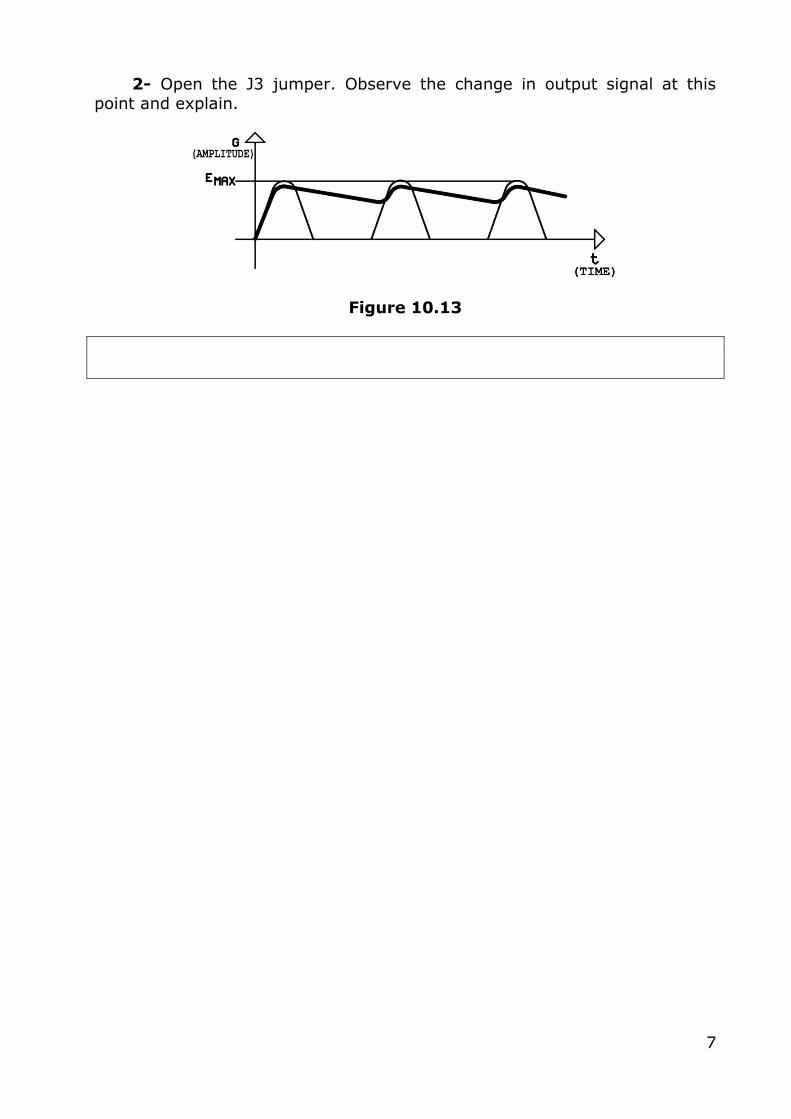
2- Open the J3 jumper. Observe the change in output signal at this
point and explain.
Figure 10.13
8
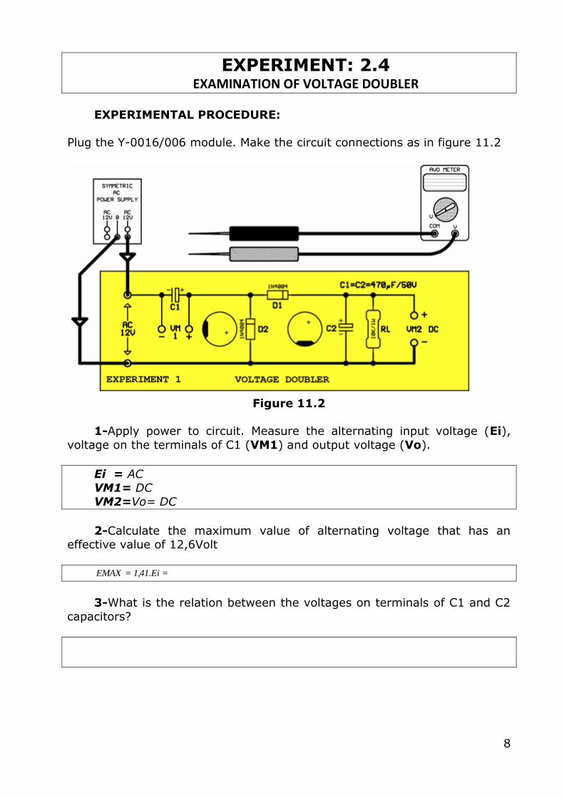
EXPERIMENT: 2.4 EXAMINATION OF VOLTAGE DOUBLER
EXPERIMENTAL PROCEDURE:
Plug the Y-0016/006 module. Make the circuit connections as in figure 11.2
Figure 11.2
1-Apply power to circuit. Measure the alternating input voltage (Ei),
voltage on the terminals of C1 (VM1) and output voltage (Vo).
Ei = AC VM1= DC
VM2=Vo= DC
2-Calculate the maximum value of alternating voltage that has an effective value of 12,6Volt
== Ei.41,1EMAX
3-What is the relation between the voltages on terminals of C1 and C2
capacitors?

9
EXPERIMENT: 2.5 EXAMINATION OF VOLTAGE TRIPPLER
EXPERIMENTAL PROCEDURE:
Plug the Y-0016/006 module. Make the circuit connections as in figure 11.4
Figure 11.4
1-Apply power to the circuit. Measure the alternating input voltage (Ei),
voltage on the terminals of each capacitor and output voltage (Vo)
Ei = AC VM1= DC VM2= DC
VM3= DC
Vo = DC
2- Does the circuit work as voltage trippler?
10
EXPERIMENT: 2.6 EXAMINATION OF VOLTAGE QUADRUPLER
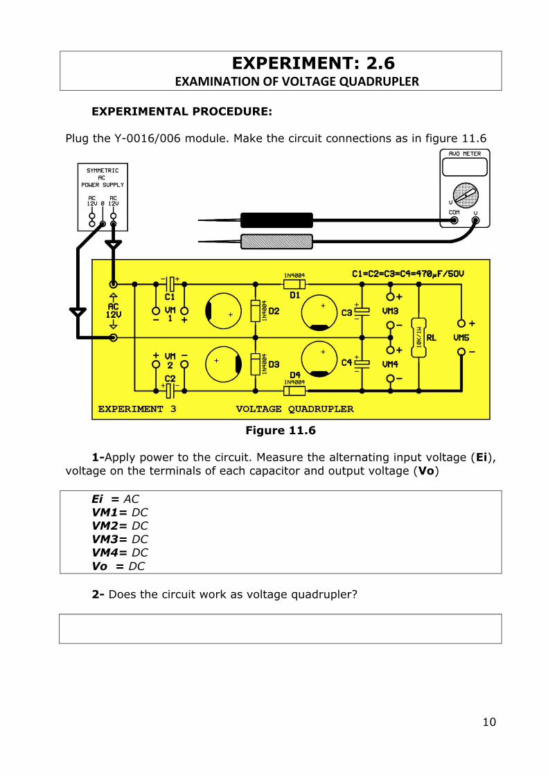
EXPERIMENTAL PROCEDURE:
Plug the Y-0016/006 module. Make the circuit connections as in figure 11.6
Figure 11.6
1-Apply power to the circuit. Measure the alternating input voltage (Ei),
voltage on the terminals of each capacitor and output voltage (Vo)
Ei = AC VM1= DC VM2= DC
VM3= DC VM4= DC
Vo = DC
2- Does the circuit work as voltage quadrupler?
Top Related